89
www.kohyd.at
www.kohyd.at

www.kohyd.at

www.kohyd.at
www.kohyd.at

www.kohyd.at

www.kohyd.at

www.kohyd.at
www.kohyd.at

www.kohyd.at

www.kohyd.at

www.kohyd.at

www.kohyd.at

www.kohyd.at

www.kohyd.at

www.kohyd.at

www.kohyd.at

www.kohyd.at

www.kohyd.at

www.kohyd.at

www.kohyd.at

www.kohyd.at

www.kohyd.at

www.kohyd.at

www.kohyd.at
www.kohyd.at

www.kohyd.at

www.kohyd.at

www.kohyd.at

www.kohyd.at

www.kohyd.at

www.kohyd.at

www.kohyd.at

www.kohyd.at

www.kohyd.at

www.kohyd.at

www.kohyd.at

www.kohyd.at

www.kohyd.at

www.kohyd.at

www.kohyd.at
www.kohyd.at


LSHT TorqmotorsTM and NicholsTM Motors110A Series HY13-1590-004/US,EU
172 Parker Hannifin Corporation
pp 172-185 110A Series SD.p65
Technical Information /TechnischeInformation / Segni / Informacion Tecnica
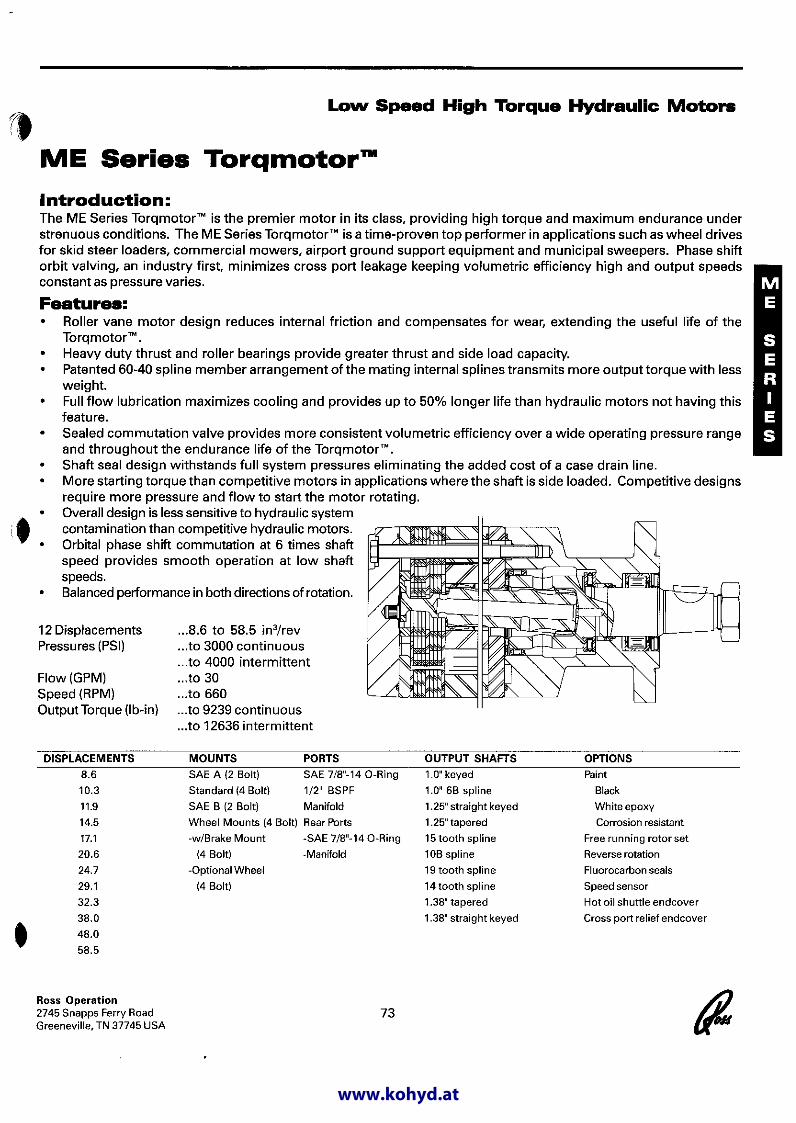
When the Ultimate in Efficiency andReliability is a MustThis high performance motor contains a power element that ispressure loaded against internal leakage for high volumetricefficiency. It is wear compensated, so that its volumetric efficiencywill not degrade with use. It can provide up to 5215 lb-in of torquethrough a one-piece solid fixed axis shaft. This shaft design allows forfull stationary spline contact between shaft and rotor, minimizingspline contact stresses. It also allows the shaft to be extendedthrough the rear cover for mounting parking brakes, auxiliary drivefunctions or encoders for speed readout or closed loop control. Lowinternal pressure drop means high mechanical efficiency and higherflow capability. This rugged motor is the most compact on the market.
7 Displacements (3.6 – 16.4 in3/rev)7 Schluckvolumen 59…269 cm3/rev7 Cylindrée7 Despazamientos
Cont IntMaximum Pressure (to 2500 psi) (to 3000 psi)Eingangsdruck …172.4 bar …206.8 barPression entréePresion Maxima
Maximum Oil Flow (to 30 gpm)Schluckstrom …113.6 lpmDébit d’huileCaudal Maximo de Aceite
Maximum Speed 858 rpmDrehzahlVitesse de rotationVelocidad Maxima
Cont IntMaximum Torque (to 4164 lb in) (to 5215 lb in)Max Drehmoment …470 Nm …589 NmCoupleTorque Maximo
Maximum Side Load at Key (to 1450 lb)Seitenlast … 6450 NCharges latèralesCarga Maxima Lateral

LSHT TorqmotorsTM and NicholsTM Motors110A Series HY13-1590-004/US,EU
173 Parker Hannifin Corporation
pp 172-185 110A Series SD.p65
Max
. di
ffere
ntia
l pr
essu
re
Max
. D
ruck
gefä
lle
Chu
te d
e pr
essi
on m
axi
Pres
ion
dife
renc
ial
max
ima
Max
. oi
l flo
wM
ax.
Schl
ucks
trom
Déb
it d´
huile
max
i
Port
ata
max
Max
. su
pply
pre
ssur
e
Max
. Ei
ngan
gsdr
uck
Pres
sion
max
i en
trée
Pres
ion
max
ima
de a
limen
taci
on
Max
. to
rque
Max
. D
rehm
omen
t
Cou
ple
max
iTo
rque
Max
imo
Max
. pe
rfor
man
ce
Max
. Le
istu
ngab
gabe
Puis
sanc
e de
sor
tie m
axi
Max
imo
rend
imen
to
Max
. sp
eed
@ M
ax.
inte
rmitt
ent
flow
Max
. D
rehz
ahl
Inte
rmitt
iere
nder
Bet
rieb:
Vite
sse
de r
otat
ion
max
i
Velo
cida
d m
axim
a a
caud
al i
nter
mite
nte
max
imo
Performance Data / LeistungsdatenPuissance / Datos Tecnicos
*
110A 036
110A 054
110A 071
110A 088
110A 106
110A 129
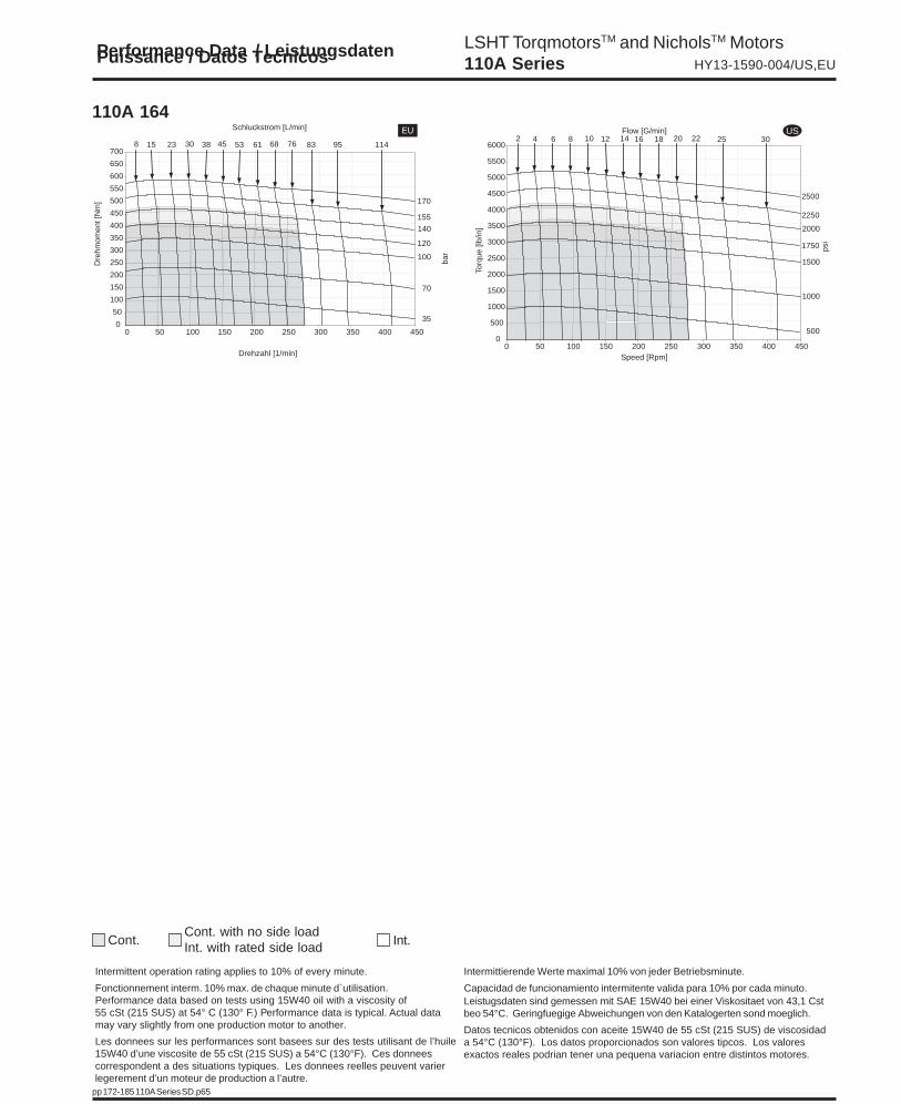
110A 164
170 2102500 3000
170 2102500 3000
170 2102500 3000
170 2102500 3000
155 2102250 3000
155 1902250 2750
140 1702000 2500
593.6
895.4
1167.1
1448.8
17410.6
21112.9
26916.4
858
740
684
622
519
437
415
45.4 5312 14
60.6 68.116 18
75.7 83.320 22
75.7 94.620 25
75.7 94.520 25
75.7 94.620 25
75.7 11420 30
127 1491125 1319
182 2131608 1884
256 3082267 2725
324 3892874 3449
352 4653115 4121
412 5033651 4453
470 5894164 5215
8.511.4
11.215.1
14.219.1
14.619.6
13.117.6
12.917.3
12.116.2
2253250
2253250
2253250
2253250
2253250
2253250
2253250
MotorSeries110A
cm3/revin3/rev
cont / int*l/ming/min
rev/min
maxbarpsi
cont / int*barpsi
cont / int*Nmlb-in
maxKWHP
Geo
met
ric
disp
lace
men
t
Geo
m.
Schl
uckv
olum
en
Cyl
indr
éeC
ilind
rata
Intermittent operation rating applies to 10% of every minute.
Intermittierende Werte maximal 10% von jeder Betriebsminute.
Fonctionnement interm. 10% max. de chaque minute d`utilisation.
Capacidad de funcionamiento intermitente valida para 10%por cada minuto.
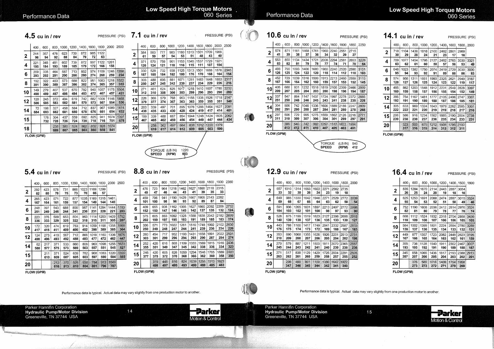
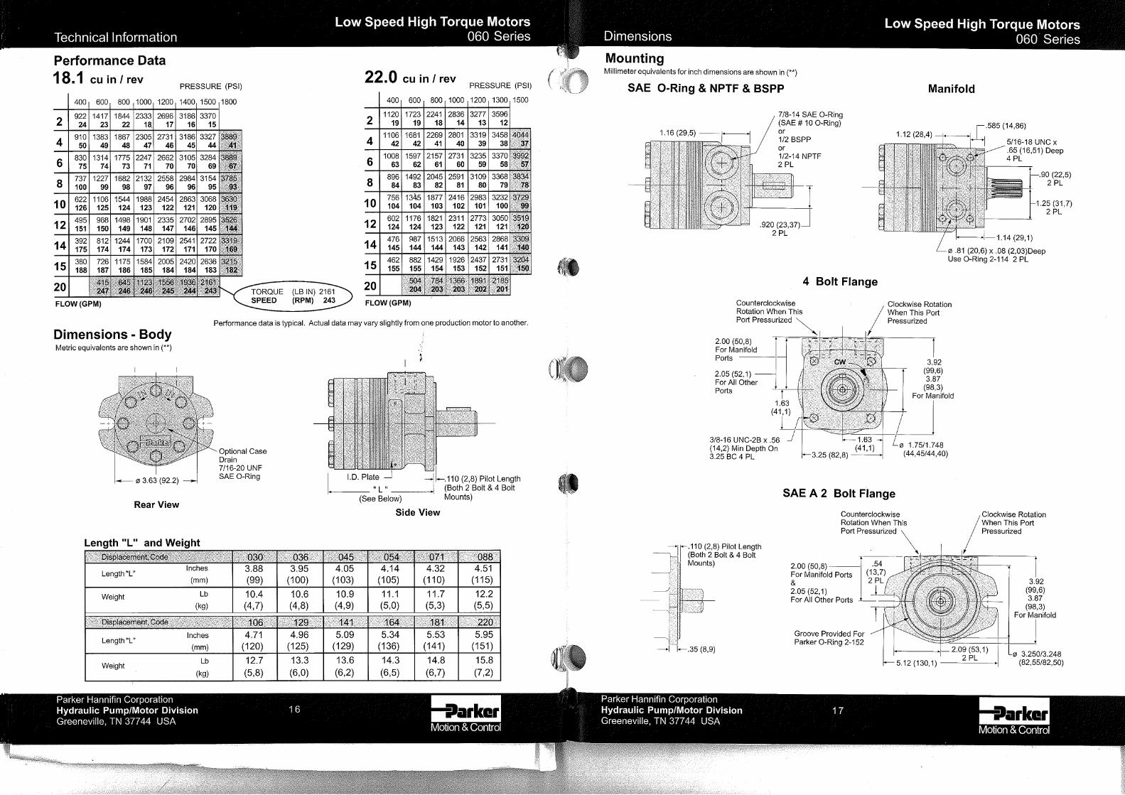
Performance data based on tests using 15W40 oil with aviscosity of 55 cSt (215 SUS) at 54° C (130° F.) Perfor-mance data is typical. Actual data may vary slightly fromone production motor to another.
Les donnees sur les performances sont basees sur destests utilisant de l’huile 15W40 d’une viscosite de 55 cSt(215 SUS) a 54°C (130°F). Ces donnees correspondent ades situations typiques. Les donnees reelles peuventvarier legerement d’un moteur de production a l’autre.
Leistugsdaten sind gemessen mit SAE 15W40 bei einerViskositaet von 43,1 Cst beo 54°C. GeringfuegigeAbweichungen von den Katalogerten sond moeglich.
Datos tecnicos obtenidos con aceite 15W40 de 55 cSt(215 SUS) de viscosidad a 54°C (130°F). Los datosproporcionados son valores tipcos. Los valores exactosreales podrian tener una pequena variacion entre distintosmotores.

LSHT TorqmotorsTM and NicholsTM Motors110A Series HY13-1590-004/US,EU
174 Parker Hannifin Corporation
pp 172-185 110A Series SD.p65
CodeSAE A 2-Bolt, Manifold
AM
SAE A 2-Bolt, 7/8”-14 SAE
AS
SAE A 2-Bolt, 1/2”-BSPP
AT
SAE B 2-Bolt, Manifold
BM
SAE B 2-Bolt, 7/8”-14 SAE
BS
11Series
Paint
XXXXMountingGehäuse
CarterMontaje
XX A
PortsAnschluß
Plan de raccordementLumbreras
X
Ordering Information / BestellschlüsselSystem de Commande / Imformacion para pedidos
DisplacementSchluckvolumen
CylindréeDesplazamiento
ShaftWelleArbreEjes
Code
036 59 / 3.6
054 89 / 5.4
071 116 / 7.1
088 144 / 8.8
106 174 / 10.6
129 211 / 12.9
164 269 / 16.4
XEngineering
Designtechnischer
EntwurfConceptiontechniqueDiseño deingeniería
X
cm³/Ucm³/trcm³/giro cu in³/rev
Thru-Shaftdurchgehende Welle
arbre traversantEje pasante
Cross-OverRelief Valve
BremslüftventilSoupape de
sûreté transversaleVálvula de
alivio transversal
CodeOmit No Paint
F Black PaintSchwarz lackiert
CodeOmit If Not Required
S Stainless Steel
Code0 No Thru Shaft1 Thru ShaftE Endcoder
Code1" Keyed
0
1" 6B Spline
1
25mm Keyed
2
1-1/4" Keyed
3
1-1/4"-14 Tooth Spline
5
7/8"-13 Tooth Spline
6
X
CodeOmit If Not RequiredR1 Cross-Over Relief Valve
Shaft MaterialWellenmaterialMatériel d'arbreMaterial del eje
Consult factory for other available options, configurations ordering codes and lead times.

LSHT TorqmotorsTM and NicholsTM Motors110A Series HY13-1590-004/US,EU
175 Parker Hannifin Corporation
pp 172-185 110A Series SD.p65
0
50
100
150
200
250
300
350
400
0 50 100 150 200 250 300 350 400 450 500 550 600 650 700 750 800
140
100
70
35
8 30 45 76 83683815 23
210
170
53 61
Drehzahl [1/min]
Schluckstrom [L/min]
Dre
hmom
ent [
Nm
]
bar
0
25
50
75
100
125
150
175
200
225
250
275
300
0 100 200 300 400 500 600 700 800
140
100
70
35
8 30 45 683815 23
210
170
53 61
Drehzahl [1/min]
Schluckstrom [L/min]
Dre
hmom
ent [
Nm
]
bar
0
25
50
75
100
125
150
175
200
0 100 200 300 400 500 600 700 800 900
100
70
35
15 30 45 5338238
140
170
210
Drehzahl [1/min]
Schluckstrom [L/min]
Dre
hmom
ent [
Nm
]
bar
0
250
500
750
1000
1250
1500
1750
2000
2250
2500
2750
3000
3250
3500
0 50 100 150 200 250 300 350 400 450 500 550 600 650 700 750
2000
1500
1000
500
2 10 14 2220124 6 8
3000
2500
16 18
Speed [Rpm]
Flow [G/min]
Torq
ue [l
b/in
]
psi
0
250
500
750
1000
1250
1500
1750
2000
2250
0 100 200 300 400 500 600 700 800
2000
1500
1000
500
2 10 14124 6 8
3000
2500
16 18
Speed [Rpm]
Flow [G/min]
Torq
ue [l
b/in
]
psi
0
250
500
750
1000
1250
1500
1750
0 100 200 300 400 500 600 700 800 900 1000
1500
1000
500
4 8 12 141062
2000
2500
3000
Speed [Rpm]
Flow [G/min]
Torq
ue [l
b/in
]
psi
110A 036
110A 054
110A 071
US
Performance Data / LeistungsdatenPuissance / Datos Tecnicos
US
US
Cont. Int.Cont. with no side loadInt. with rated side load
Intermittent operation rating applies to 10% of every minute. Intermittierende Werte maximal 10% von jeder Betriebsminute.
Fonctionnement interm. 10% max. de chaque minute d`utilisation. Capacidad de funcionamiento intermitente valida para 10% por cada minuto.Performance data based on tests using 15W40 oil with a viscosity of55 cSt (215 SUS) at 54° C (130° F.) Performance data is typical. Actual datamay vary slightly from one production motor to another.
Les donnees sur les performances sont basees sur des tests utilisant de l’huile15W40 d’une viscosite de 55 cSt (215 SUS) a 54°C (130°F). Ces donneescorrespondent a des situations typiques. Les donnees reelles peuvent varierlegerement d’un moteur de production a l’autre.
Leistugsdaten sind gemessen mit SAE 15W40 bei einer Viskositaet von 43,1 Cstbeo 54°C. Geringfuegige Abweichungen von den Katalogerten sond moeglich.
Datos tecnicos obtenidos con aceite 15W40 de 55 cSt (215 SUS) de viscosidada 54°C (130°F). Los datos proporcionados son valores tipcos. Los valoresexactos reales podrian tener una pequena variacion entre distintos motores.

LSHT TorqmotorsTM and NicholsTM Motors110A Series HY13-1590-004/US,EU
176 Parker Hannifin Corporation
pp 172-185 110A Series SD.p65
0
50
100
150
200
250
300
350
400
450
500
550
0 50 100 150 200 250 300 350 400 450 500
140
100
70
35
8 30 45 76683815 23
170
53 61 83 95
190
155
120
Drehzahl [1/min]
Schluckstrom [L/min]
Dre
hmom
ent [
Nm
]
bar
0
50
100
150
200
250
300
350
400
450
500
0 100 200 300 400 500 600
140
100
70
35
8 30 45 76683815 23
210
170
53 61
190
155
120
9583
Drehzahl [1/min]
Schluckstrom [L/min]
Dre
hmom
ent [
Nm
]
bar
0
50
100
150
200
250
300
350
400
450
500
0 100 200 300 400 500 600 700
140
100
70
35
8 30 45 76683815 23
210
170
53 61 83 95
Drehzahl [1/min]
Schluckstrom [L/min]
Dre
hmom
ent [
Nm
]
bar
0
500
1000
1500
2000
2500
3000
3500
4000
4500
5000
0 50 100 150 200 250 300 350 400 450 500
2000
1500
1000
500
2 10 14 2220124 6 8
2500
16 18 25
2750
2250
1750
Speed [Rpm]
Flow [G/min]
Torq
ue [l
b/in
]
psi
0
500
1000
1500
2000
2500
3000
3500
4000
4500
5000
0 100 200 300 400 500 600
2000
1500
1000
500
2 10 14 2220124 6 8
3000
2500
16 18
2750
2250
1750
25
Speed [Rpm]
Flow [G/min]
Torq
ue [l
b/in
]
psi
0
500
1000
1500
2000
2500
3000
3500
4000
0 100 200 300 400 500 600 700
2000
1500
1000
500
2 10 14 2220124 6 8
3000
2500
16 18 25
Speed [Rpm]
Flow [G/min]
Torq
ue [l
b/in
]
psi
110A 088
110A 106
110A 129
US
Performance Data / LeistungsdatenPuissance / Datos Tecnicos
Cont. Int.Cont. with no side loadInt. with rated side load
US
Intermittent operation rating applies to 10% of every minute. Intermittierende Werte maximal 10% von jeder Betriebsminute.
Fonctionnement interm. 10% max. de chaque minute d`utilisation. Capacidad de funcionamiento intermitente valida para 10% por cada minuto.Performance data based on tests using 15W40 oil with a viscosity of55 cSt (215 SUS) at 54° C (130° F.) Performance data is typical. Actual datamay vary slightly from one production motor to another.
Les donnees sur les performances sont basees sur des tests utilisant de l’huile15W40 d’une viscosite de 55 cSt (215 SUS) a 54°C (130°F). Ces donneescorrespondent a des situations typiques. Les donnees reelles peuvent varierlegerement d’un moteur de production a l’autre.
Leistugsdaten sind gemessen mit SAE 15W40 bei einer Viskositaet von 43,1 Cstbeo 54°C. Geringfuegige Abweichungen von den Katalogerten sond moeglich.
Datos tecnicos obtenidos con aceite 15W40 de 55 cSt (215 SUS) de viscosidada 54°C (130°F). Los datos proporcionados son valores tipcos. Los valoresexactos reales podrian tener una pequena variacion entre distintos motores.
US
LSHT TorqmotorsTM and NicholsTM Motors110A Series HY13-1590-004/US,EU
177 Parker Hannifin Corporation
pp 172-185 110A Series SD.p65
0
50
100
150
200
250
300
350
400
450
500
550
600
650
700
0 50 100 150 200 250 300 350 400 450
140
100
70
35
8 30 45 76683815 23
155
53 61
170
120
83 95 114
Drehzahl [1/min]
Schluckstrom [L/min]
Dre
hmom
ent [
Nm
]
bar
0
500
1000
1500
2000
2500
3000
3500
4000
4500
5000
5500
6000
0 50 100 150 200 250 300 350 400 450
2000
1500
1000
500
2 10 14 2220124 6 8
2250
16 18
2500
1750
25 30
Speed [Rpm]
Flow [G/min]
Torq
ue [l
b/in
]
psi
110A 164
Performance Data / LeistungsdatenPuissance / Datos Tecnicos
Cont. Int.Cont. with no side loadInt. with rated side load
US
Intermittent operation rating applies to 10% of every minute. Intermittierende Werte maximal 10% von jeder Betriebsminute.
Fonctionnement interm. 10% max. de chaque minute d`utilisation. Capacidad de funcionamiento intermitente valida para 10% por cada minuto.Performance data based on tests using 15W40 oil with a viscosity of55 cSt (215 SUS) at 54° C (130° F.) Performance data is typical. Actual datamay vary slightly from one production motor to another.
Les donnees sur les performances sont basees sur des tests utilisant de l’huile15W40 d’une viscosite de 55 cSt (215 SUS) a 54°C (130°F). Ces donneescorrespondent a des situations typiques. Les donnees reelles peuvent varierlegerement d’un moteur de production a l’autre.
Leistugsdaten sind gemessen mit SAE 15W40 bei einer Viskositaet von 43,1 Cstbeo 54°C. Geringfuegige Abweichungen von den Katalogerten sond moeglich.
Datos tecnicos obtenidos con aceite 15W40 de 55 cSt (215 SUS) de viscosidada 54°C (130°F). Los datos proporcionados son valores tipcos. Los valoresexactos reales podrian tener una pequena variacion entre distintos motores.

LSHT TorqmotorsTM and NicholsTM Motors110A Series HY13-1590-004/US,EU
178 Parker Hannifin Corporation
pp 172-185 110A Series SD.p65
Distance From Mounting Face - mm (in)
Radial Load - N (lb)
Radial Load / Radiale WellenbelastungCharges Radiale / Carga Radial
The allowable side load curve is based on L10 bushing life of 3 x 10⁶ revolutions @ 100 RPM.Die zulassige radiale Wellenbelastung bezieht sich auf die Lager-Lebensdauer 3 x 10⁶ Umdrehungen.L’effort radial admissible sur l’arbre depend a une duree de vie 3 x 10⁶ de rotation.La curva de carga lateral admisible se basa en vida util de cojinete de 3 x 10 revoluciones.
0
13345(3000)
11121(2500)
8896(2000)
6672(1500)
4448(1000)
2224(500)
0-50.8(-2)
-25.4(-1)
0(0)
25.4(1)
50.8(2)
76.2(3)
112.9 (1000)
225.9 (2000)
338.9 (3000)
451.9 (4000)
519.7 (5000)
Torquenm (lb-in)

LSHT TorqmotorsTM and NicholsTM Motors110A Series HY13-1590-004/US,EU
179 Parker Hannifin Corporation
pp 172-185 110A Series SD.p65
Mounting,Ports/Gehäuse,AnschlüßeCarter,Orifices / Montaje,Lumbreras
59.9 (2.36)58.5 (2.305)For Manifold
117.1(4.61)115.6 (4.55)For Manifold
2X 14.2 (.56)
22.99 (.905)
22.99 (.905)
106.4(4.188)
130.3(5.13)Max
B
A
11.2 (.44)
28.5 (1.12)
Ø 82.55 (3.250)
2 X 31.88 (1.255)
"L"
7/16-20 STRAIGHT THDO-RING CASE DRAIN
3.1 (.12)
Ø 114.3 (4.50)
A
B
15.7 (.62)
2 x 14.2 (.56)2x 31.8 (1.25)
2x 22.9 (.90)
4x 5/16-18 UNC-2Bx 12.7 (.50) Min Full Threadø 20.62 (.812) x 2.03 (.080) Deep
Code: AM
SAE A 2-Bolt,Manifold
Code AM 036 054 071 088 106 129 164
Weight/Gewicht kg 7.0 7.4 7.7 8.0 8.4 8.7 9.4
Poids/Peso (lb) (15.4) (16.2) (16.9) (17.5) (18.4) (19.1) (20.6)
Length "L" mm 112 117 121 127 131 138 147
"L" (in) (4.41) (4.60) (4.78) (4.98) (5.17) (5.42) (5.80)
English equivalents for metric specifications are shown in ( ).
59.9 (2.36)58.5 (2.305)For Manifold
117.1(4.61)115.6 (4.55)For Manifold
2X 14.2 (.56)
22.99 (.905)
22.99 (.905)
106.4(4.188)
130.3(5.13)Max
B
A
11.2 (.44)
28.5 (1.12)
Ø 82.55 (3.250)
2 X 31.88 (1.255)
"L"
7/16-20 STRAIGHT THDO-RING CASE DRAIN
3.1 (.12)
Ø 114.3 (4.50)
A
B
15.7 (.62)
2 x 25.4 (1.00)
7/8-14 SAE O-Ring
Code: AS
SAE A 2-Bolt,7/8“-14 SAEO-Ring
Code AS 036 054 071 088 106 129 164
Weight/Gewicht kg 7.0 7.4 7.7 8.0 8.4 8.7 9.4
Poids/Peso (lb) (15.4) (16.2) (16.9) (17.5) (18.4) (19.1) (20.6)
Length "L" mm 112 117 121 127 131 138 147
"L" (in) (4.41) (4.60) (4.78) (4.98) (5.17) (5.42) (5.80)
Motor with manifold mount is supplied with 2 O-rings.
Zum Motor mit Universalanschluß werden 2 O-Ringe geliefert.
Deux joints toriques sont livrés avec les moteurs a plan de raccordement universel.
Il blocchetto connessioni é corredato da 2 OR.
2.03(0.80)
20.62(0.812)
O-rings
LSHT TorqmotorsTM and NicholsTM Motors110A Series HY13-1590-004/US,EU
180 Parker Hannifin Corporation
pp 172-185 110A Series SD.p65
59.9 (2.36)58.5 (2.305)For Manifold
117.1(4.61)115.6 (4.55)For Manifold
2X 14.2 (.56)
22.99 (.905)
22.99 (.905)
106.4(4.188)
130.3(5.13)Max
B
A
11.2 (.44)
28.5 (1.12)
Ø 82.55 (3.250)
2 X 31.88 (1.255)
"L"
7/16-20 STRAIGHT THDO-RING CASE DRAIN
3.1 (.12)
Ø 114.3 (4.50)
A
B
15.7 (.62)
2 x 25.4 (1.00)
1/2 BSPP
A
B B
A
14.0 (.55)
29.2 (1.15)
Ø 101.57 (3.999)
2 X 31.88 (1.255)
22.99 (.905)
"L"
7/16-20 STRAIGHT THDO-RING CASE DRAIN
143.8(5.66)
2X 14.2 (.56)6.4 (.25)
22.99 (.905)
Ø 114.3 (4.50)
60.2 (2.37)58.55 (2.305)For Manifold
176.0(6.93)Max
120.7 (4.75)118.75 (4.675)For Manifold
15.7 (.62) 2 x 14.2 (.56)
2x 31.8 (1.25)
2x 22.9 (.90)
4x 5/16-18 UNC-2Bx 12.7 (.50) Min Full Threadø 20.62 (.812) x 2.03 (.080) Deep
English equivalents for metric specifications are shown in ( ).
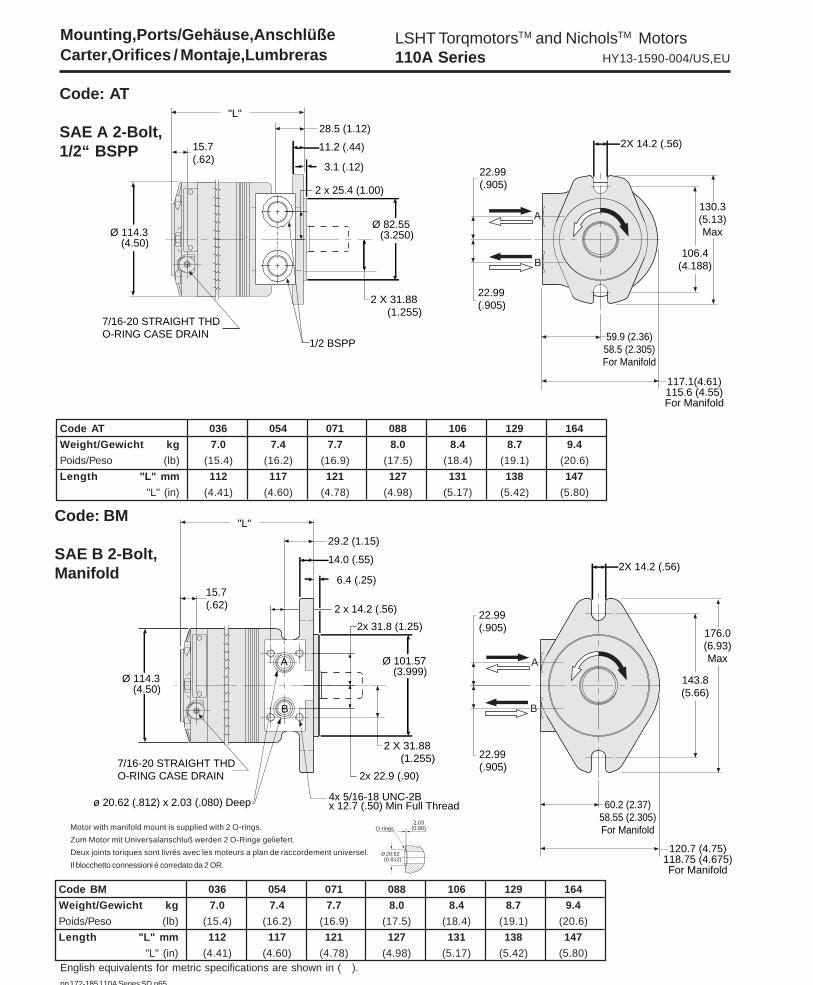
Code: AT
SAE A 2-Bolt,1/2“ BSPP
Code AT 036 054 071 088 106 129 164
Weight/Gewicht kg 7.0 7.4 7.7 8.0 8.4 8.7 9.4
Poids/Peso (lb) (15.4) (16.2) (16.9) (17.5) (18.4) (19.1) (20.6)
Length "L" mm 112 117 121 127 131 138 147
"L" (in) (4.41) (4.60) (4.78) (4.98) (5.17) (5.42) (5.80)
Code: BM
SAE B 2-Bolt,Manifold
Code BM 036 054 071 088 106 129 164
Weight/Gewicht kg 7.0 7.4 7.7 8.0 8.4 8.7 9.4
Poids/Peso (lb) (15.4) (16.2) (16.9) (17.5) (18.4) (19.1) (20.6)
Length "L" mm 112 117 121 127 131 138 147
"L" (in) (4.41) (4.60) (4.78) (4.98) (5.17) (5.42) (5.80)
Motor with manifold mount is supplied with 2 O-rings.
Zum Motor mit Universalanschluß werden 2 O-Ringe geliefert.
Deux joints toriques sont livrés avec les moteurs a plan de raccordement universel.
Il blocchetto connessioni é corredato da 2 OR.
2.03(0.80)
20.62(0.812)
O-rings
Mounting,Ports/Gehäuse,AnschlüßeCarter,Orifices / Montaje,Lumbreras

LSHT TorqmotorsTM and NicholsTM Motors110A Series HY13-1590-004/US,EU
181 Parker Hannifin Corporation
pp 172-185 110A Series SD.p65
Mounting,Ports/Gehäuse,AnschlüßeCarter,Orifices / Montaje,Lumbreras
A
B B
A
14.0 (.55)
29.2 (1.15)
Ø 101.57 (3.999)
2 X 31.88 (1.255)
22.99 (.905)
"L"
7/16-20 STRAIGHT THDO-RING CASE DRAIN
143.8(5.66)
2X 14.2 (.56)6.4 (.25)
22.99 (.905)
Ø 114.3 (4.50)
60.2 (2.37)58.55 (2.305)For Manifold
176.0(6.93)Max
120.7 (4.75)118.75 (4.675)For Manifold
15.7 (.62)
2x 25.4 (1.00)
7/8-14 SAE O-Ring
English equivalents for metric specifications are shown in ( ).
Code: BS
SAE B 2-Bolt,7/8“-14 SAEO-Ring
Code BS 036 054 071 088 106 129 164
Weight/Gewicht kg 7.0 7.4 7.7 8.0 8.4 8.7 9.4
Poids/Peso (lb) (15.4) (16.2) (16.9) (17.5) (18.4) (19.1) (20.6)
Length "L" mm 112 117 121 127 131 138 147
"L" (in) (4.41) (4.60) (4.78) (4.98) (5.17) (5.42) (5.80)
Motor with manifold mount is supplied with 2 O-rings.
Zum Motor mit Universalanschluß werden 2 O-Ringe geliefert.
Deux joints toriques sont livrés avec les moteurs a plan de raccordement universel.
Il blocchetto connessioni é corredato da 2 OR.
2.03(0.80)
20.62(0.812)
O-rings

LSHT TorqmotorsTM and NicholsTM Motors110A Series HY13-1590-004/US,EU
182 Parker Hannifin Corporation
pp 172-185 110A Series SD.p65
Code B
Code A
45.5(1.79)
45.5(1.79)
54.6(2.15)
53.8(2.12)
Shafts / AbtriebswellenArbre / Ejes
English equivalents for metric specifications are shown in ( ).
Code: 0
1" Keyed
Code: 1
1" 6B Spline
Code: 2
25mm Keyed
Code: 3
1-1/4" Keyed

LSHT TorqmotorsTM and NicholsTM Motors110A Series HY13-1590-004/US,EU
183 Parker Hannifin Corporation
pp 172-185 110A Series SD.p65
41.38 (1.629)
25.000 (.9843)
M8x1.25H-6Hx16.0(.63) Min Deep
Key A8x7x32mm
37.39 (1.472) .315.314
(8mm)
20.9 (.826)
ø 25.37
(.999)
1/4-20 UNC thd
x 15.75 (.62) Min Deep
Key 1/4 x 1 Woodruff
#15 Per SAE J502
18.6 (.73)
28.4(1.120)
6.37 (.251)
English equivalents for metric specifications are shown in ( ).
Shafts / AbtriebswellenArbre / Ejes
Code: 2
25mm Keyed
Code: 1
1" 6B Spline
Code: 0
1" Keyed
25.4 (1.00) MinFull Spline
SAE 6B
ø 25.30(.996)
1/4-20 UNC thdx 15.75 (.62) Min Deep
ø 25.27(.995)
47.8 (1.88)39.4 (1.55)
x 7.95 (.313)
ø 31.737(1.2495)
3/8-16 UNC thdx 19.05 (.75) Min Deep
Key 7.950 x 31.5 (.3130 x 1.24) Square
34.9(1.373)
7.96 (.3135)
Code: 3
1-1/4" Keyed

LSHT TorqmotorsTM and NicholsTM Motors110A Series HY13-1590-004/US,EU
184 Parker Hannifin Corporation
pp 172-185 110A Series SD.p65
53.8(2.12)
45.5(1.79)
Code B
Code A
English equivalents for metric specifications are shown in ( ).
Code: 5
1-1/4"-14 Tooth Spline
Code: 6
7/8"-13 Tooth Spline

LSHT TorqmotorsTM and NicholsTM Motors110A Series HY13-1590-004/US,EU
185 Parker Hannifin Corporation
pp 172-185 110A Series SD.p65
English equivalents for metric specifications are shown in ( ).
Code: 6
7/8"-13 Tooth Spline
Code: 5
1-1/4"-14 Tooth Spline ø 31.153(1.2265)
3/8-16 UNC thdx 19.05 (.75) Min Deep
47.7 (1.88)
33.0 (1.3) MinFull Spline
ø 31.67(1.247)
25.4 (1.00)Min Full Spline13 Tooth 16/32
ø 22.162(.8725)
1/4-20 UNC thdx 15.75 (.62) Min Deep
ø 25.27 (.995)
1/4-20 UNC-2Bx 15.7 (.62) Min Full Thd

www.kohyd.at

www.kohyd.at

www.kohyd.at

www.kohyd.at

www.kohyd.at

www.kohyd.at
www.kohyd.at
www.kohyd.at


DRIVE RATIOS with PULLEYS & BELTSSAME SPEED & SAME TORQUE
A Motor running at 600 RPM Speed and 2,500 pounds pressurerequires 16 gallons and develops 1,600 inch-pounds of torque and 15horsepower. With a 4-inch driving and a 4-inch driven pulley (1 to 1 ratio),this torque and horsepower are transmitted to the driven shaft. The drivenshaft has 600 RPM speed and 1,600 inch-pounds of torque and 15 horse-power.
SPEED REDUCTION & TORQUE INCREASE
A Motor running at 600 RPM Speed and 2,500 pounds pressurerequires 16 gallons and develops 1,600 inch-pounds of torque. With a 4-inch drive pulley and a 16-inch driven pulley (1 to 4 ratio) it runs the equip-ment at 150 RPM speed and develops 6,400 inch-pounds of torque and15 horsepower.
SPEED INCREASE & TORQUE REDUCTION
A Motor running at 600 RPM Speed and 2,500 pounds pressurerequires 16 gallons and develops 1,600 inch-pounds of torque. With a 16-inch drive pulley and a 4-inch driven pulley (4 to 1 ratio) it runs the equip-ment at 2,400 RPM speed and develops 400 inch-pounds of torque and15 horsepower.
SPEED REDUCTION SPEED INCREASEAND TORQUE AND TORQUE
INCREASE REDUCTION
TRW ROSS TORQMOTORS
MPH vs RPM & Flow with Different Rolling Radius Wheels
HOW TO MEASURE TORQUE K1REQUIRED FOR A MOTOR
TORQUE is important because it is the measurement of rotary orturning force. Torque is expressed in inch-pounds.
A simple spring scale and a wrench can be used to determine theamount of torque required to turn a shaft. Place a 12 inch pipe wrench onthe shaft, attaching the wrench’s handle to the spring scale. Pull on theother end of the scale, reading the dial when the shaft moves. This figure(number of pounds) when multiplied by the length of the wrench (in thiscase 12 inches) will give the torque required to turn the shaft.
EXAMPLE: A 50 pound pull on the end of a 12 inch wrench indicates600 inch-pounds of torque (50 x 12 = 600).
TORQUE HORSEPOWER SPEED RELATIONSHIPFOR HYDRAULIC MOTORS
RULE OF THUMB FOR HYDRAULIC MOTOR APPLICATIONSWhere Gasoline Engines or Electric Motors Are Now Used
1 Electric Motor H.P. Equals 1-1/2 Hydraulic Motor H.P.1 Gasoline Engine H.P. Equals 3/4 Hydraulic Motor H.P.1 Hydraulic Motor H.P. Equals 1-2/3 Gasoline Engine H.P.1 Hydraulic Motor H.P. Equals 2/3 Electric Engine H.P.1 Electric Motor H.P. Equals 2-1/2 Gasoline Engine H.P.
Prices subject to change without notice*
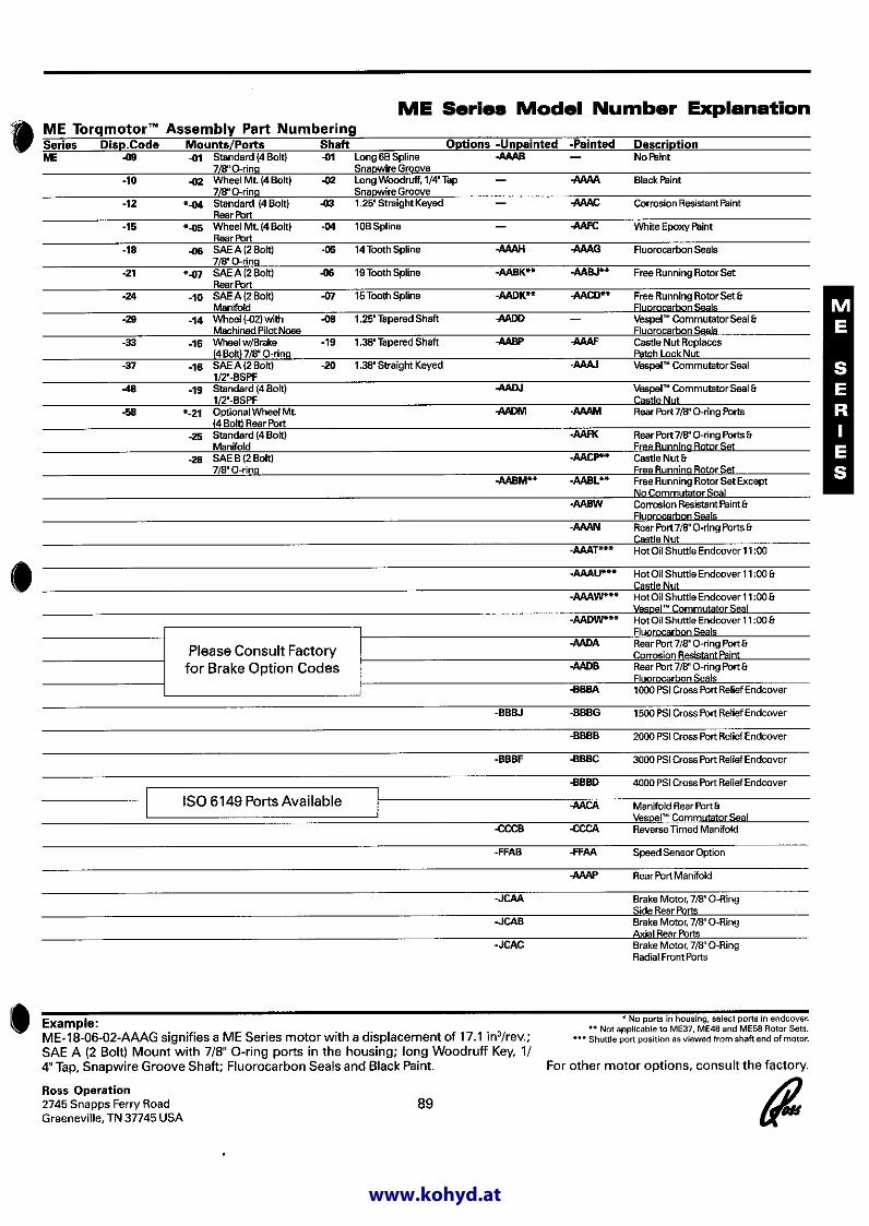
TF and TG SERIES MODEL NUMBER EXPLANATIONExample: TF0080-US-080-AAAA This model number identifies an MB series motor with a 5 in 3/revolution displacement, a standard mount housingwith 7/8 inch O-Ring, a long 6B shaft with snapwire groove and standard black paint.
DisplacementsTF Series TG Series Cu. Inch/rev Housing Shaft Option
TF0080 4.9 -MF Standard mount 7/8 O-Ring -01 Long 6B snapwire groove -AAAATF0100 6.1 -US Long wheel mount 7/8 O-Ring -02 Long Woodruff, 1/4” tap “Standard”TF0130 7.8 snapwire groove black paintTF0140 8.6 -MB Standard mount rearport -03 1.25” straight keyed -AAABTF0170 10.3 -UB Long wheel mount rearport -04 10B spline UnpaintedTF0195 TG0195 12.0 -AS SAE 2 bolt 7/8 O-Ring -05 14 tooth splineTF0240 TG0240 14.5 -AB SAE 2 bolt rearport -06 19 tooth splineTF0280 TG0280 17.1 -07 15 tooth spline
TG0335 20.6 -08 1.25” tapered shaftTF0405 TG0405 24.7 -19 1.38” tapered shaft
TG0475 29.1 -20 1.38” straight keyed shaftTG0530 32.3TG0625 38.0TG0785 48.0TG0960 58.5

K2 YOUR STANDARD DUTY HYDRAULIC MOTOR GUIDE
TB Torqmotor Series Dimensions
5 HP up to 9 HP Roller Stator - Two Bronze Bushings and One Needle Thrust Bearing
NEW OLD RPM Max. | At 5 GPM | HP at 50 RPMRoss Motor Ross Motor Similar to Max. Max. Max. No Cont. | Max Cont. PSI | Max. Cont. PSINumber Number CharLynn &/or White PSI Disp Torq Flow Load PSI | RPM HP | GPM HP
TB0045FP130AAAB MG 021313AAAB 2300 2 707 9 88 1800 | 395 2.5 | .60 .44TB0045FP110AAAB MG 021311AAAB 2300 2 707 9 88 1800 | 395 2.5 | .60 .44TB0045AP130AAAB MG 021213AAAB 2300 2 707 9 88 1800 | 395 2.5 | .60 .44TB0045AP110AAAB MG 021211AAAB 2300 2 707 9 88 1800 | 395 2.5 | .60 .44TB0050FP130AAAB MG 031313AAAB 101-1001 RSAA1 2300 3 879 9 76 1800 | 354 3.0 | .70 .50TB0050FP110AAAB MG 031311AAAB RSAA6 2300 3 879 9 76 1800 | 354 3.0 | .70 .50TB0050AP130AAAB MG 031213AAAB 101-1025 RSDA1 2300 3 879 9 76 1800 | 354 3.0 | .70 .50TB0050AP110AAAB MG 031211AAAB 101-1073 RSDA6 2300 3 879 9 76 1800 | 354 3.0 | .70 .50TB0065FP130AAAB MG 041313AAAB 101-1002 RSAB1 2200 4 1106 9 57 1800 | 276 3.125 | .90 .70TB0065FP110AAAB MG 041311AAAB RSAB6 2200 4 1106 9 57 1800 | 276 3.125 | .90 .70TB0065AP130AAAB MG 041213AAAB 101-1026 RSDB1 2200 4 1106 9 57 1800 | 276 3.125 | .90 .70TB0065AP110AAAB MG 041211AAAB 101-1074 RSDB6 2200 4 1106 9 57 1800 | 276 3.125 | .90 .70TB0080FP130AAAB MG 051313AAAB 2200 5 1387 9 45 1800 | 208 4.5 | 1.19 .90TB0080FP110AAAB MG 051311AAAB 2200 5 1387 9 45 1800 | 208 4.5 | 1.19 .90TB0080AP130AAAB MG 051213AAAB 2200 5 1387 9 45 1800 | 208 4.5 | 1.19 .90TB0080AP110AAAB MG 051211AAAB 2200 5 1387 9 45 1800 | 208 4.5 | 1.19 .90TB0100FP130AAAB MG 061313AAAB 101-1003 RSAC1 2000 6 1501 12 38 1800 | 179 3.0 | 1.40 1.00TB0100FP110AAAB MG 061311AAAB 101-1051 RSAC6 2000 6 1501 12 38 1800 | 179 3.0 | 1.40 1.00TB0100AP130AAAB MG 061213AAAB 101-1027 RSDC1 2000 6 1501 12 38 1800 | 179 3.0 | 1.40 1.00TB0100AP110AAAB MG 061211AAAB 101-1075 RSDC6 2000 6 1501 12 38 1800 | 179 3.0 | 1.40 1.00TB0130FP130AAAB MG 081313AAAB 2000 8 2044 15 28 1800 | 135 3.187 | 1.80 1.46TB0130FP110AAAB MG 081311AAAB 2000 8 2044 15 28 1800 | 135 3.187 | 1.80 1.46TB0130AP130AAAB MG 081213AAAB 2000 8 2044 15 28 1800 | 135 3.187 | 1.80 1.46TB0130AP110AAAB MG 081211AAAB 2000 8 2044 15 28 1800 | 135 3.187 | 1.80 1.46TB0165FP130AAAB MG 101313AAAB 101-1004 RSAE1 2000 10 2515 15 23 1800 | 110 3-1/5 | 2.30 1.80TB0165FP110AAAB MG 101311AAAB 101-1052 RSAE6 2000 10 2515 15 23 1800 | 110 3-1/5 | 2.30 1.80TB0165AP130AAAB MG 101213AAAB 101-1028 RSDE1 2000 10 2515 15 23 1800 | 110 3-1/5 | 2.30 1.80TB0165AP110AAAB MG 101211AAAB 101-1076 RSDE6 2000 10 2515 15 23 1800 | 110 3-1/5 | 2.30 1.80TB0195FP130AAAB MG 121313AAAB 101-1005 RSAG1 2000 12 3028 15 19 1800 | 91 3.125 | 2.70 2.20TB0195FP110AAAB MG 121311AAAB 101-1053 RSAG6 2000 12 3028 15 19 1800 | 91 3.125 | 2.70 2.20TB0195AP130AAAB MG 121213AAAB 101-1029 RSDG1 2000 12 3028 15 19 1800 | 91 3.125 | 2.70 2.20TB0195AP110AAAB MG 121211AAAB 101-1077 RSDG6 2000 12 3028 15 19 1800 | 91 3.125 | 2.70 2.20TB0230FP130AAAB MG 141313AAAB 101-1006 RSAK1 2000 14 3495 15 17 1500 | 79 3.187 | 3.15 2.00TB0230FP110AAAB MG 141311AAAB 101-1054 RSAK6 2000 14 3495 15 17 1500 | 79 3.187 | 3.15 2.00TB0230AP130AAAB MG 141213AAAB 101-1030 RSDK1 2000 14 3495 15 17 1500 | 79 3.187 | 3.15 2.00TB0230AP110AAAB MG 141211AAAB 101-1078 RSDK6 2000 14 3495 15 17 1500 | 79 3.187 | 3.15 2.00TB0260FP130AAAB MG 161313AAAB 1500 16 2924 15 14 1450 | 68 2.36 | 3.60 2.00TB0260FP110AAAB MG 161311AAAB 1500 16 2924 15 14 1450 | 68 2.36 | 3.60 2.00TB0260AP130AAAB MG 161213AAAB 1500 16 2924 15 14 1450 | 68 2.36 | 3.60 2.00TB0260AP110AAAB MG 161211AAAB 1500 16 2924 15 14 1450 | 68 2.36 | 3.60 2.00TB0295FP130AAAB MG 181313AAAB 101-1007 RSAM1 1400 18 2993 15 13 1400 | 62 2-1/5 | 4.00 2.50TB0295FP110AAAB MG 181311AAAB 101-1055 RSAM6 1400 18 2993 15 13 1400 | 62 2-1/5 | 4.00 2.50TB0295AP130AAAB MG 181213AAAB 101-1031 RSDM1 1400 18 2993 15 13 1400 | 62 2-1/5 | 4.00 2.50TB0295AP110AAAB MG 181211AAAB 101-1079 RSDM6 1400 18 2993 15 13 1400 | 62 2-1/5 | 4.00 2.50TB0330FP130AAAB MG 201313AAAB 101-1008 RSAP1 1400 20 3411 15 11 1350 | 55 1.875 | 4.60 2.60TB0330FP110AAAB MG 201311AAAB 101-1056 RSAP6 1400 20 3411 15 11 1350 | 55 1.875 | 4.60 2.60TB0330AP130AAAB MG 201213AAAB 101-1032 RSDP1 1400 20 3411 15 11 1350 | 55 1.875 | 4.60 2.60TB0330AP110AAAB MG 201211AAAB 101-1080 RSDP6 1400 20 3411 15 11 1350 | 55 1.875 | 4.60 2.60
NOTE: At Constant Pressure and Constant Flow the Horsepower will be the same and the RPM will vary as the displacement varies. With a constantRPM and a constant PSI the horsepower will increase with an increase in displacement.
Prices subject to change without notice

Date: 2500 Use TRW ROSS “TB” SERIES MOTORS K3For CHAR-LYNN “H” SERIES OR WHITE “RS” SERIES MOTORS
TB Series Roller Stator Has Two Bronze Bushings and One Needle Thrust BearingWhite Motors and Ross Motors rotate in the same direction as Char-Lynn Motors
All Motors are reversible
HOW TO IDENTIFY A CHAR-LYNN MOTORMeasure the width of the gerotor gear just before the end cap of themotor. The width will be either 1/4, 3/8, 1/2, 3/4, 7/8, 1, 1-1/4, 1-1/2, or2 inches. You can easily identify the motor using the fourth columnfrom the left.
4-Bolt Mount has 3-1/4” bolt circle & a 1-3/4” round pilot.
The hydraulic pumping & commutating action takes place at high-speed; &the output shaft rotates at the slow-speed, high torque. The output shaft isdesigned to accept heavy side loads and has an outboard shaft bearing. The torque that the motor delivers to the output shaft is dependent uponthe pressure of the oil. The RPM of the output shaft is dependent upon thegallons per minute being pumped.
2-Bolt Flange mount will match SAE type A Mount-Bolts are 4-3/16” centerto center with 3-1/4” round pilot.
The positive displacement hydraulic motor utilizes planetary gear action inthe driven members to multiply actual displacement and torque by six; thuscreating a low-speed, high torque hydraulic motor.
With 1/2” PIPE PORTS | With 7/8” O-RING PORTS| NEW | NEW Old
NEW | Char- Char- OLD | Char- Char- OLDTRW-Ross Our | Aprox. Lynn Lynn TRW-Ross White | Lynn Lynn TRW-Ross WhiteMotor Sequence Per | Disp. Gerotor Motor Motor Motor | Motor Motor Motor MotorNumber Number Each | Cu.In. Width Number Number Number | Number Number Number Number
4-Bolt Light Mounting Flange-1” Straight Shaft with Key |TB0045FP130AAAB 706958 $387.26 | 2 MG 021313AAAB | MG 020913AAABTB0050FP130AAAB 706963 388.36 | 3 1/4 101-1001 MG 031313AAAB RSAA1 | 101-1009 BA1 MG 030913AAAB RSBA1TB0065FP130AAAB 706968 389.46 | 4 3/8 101-1002 MG 041313AAAB RSAB1 | 101-1010 BB1 MG 040913AAAB RSBB1TB0080FP130AAAB 706969 382.86 | 5 MG 051313AAAB | MG 050913AAABTB0100FP130AAAB 706973 401.56 | 6 1/2 101-1003 MG 061313AAAB RSAC1 | 101-1011 BC1 MG 060913AAAB RSBC1TB0130FP130AAAB 706974 399.36 | 8 MG 081313AAAB | MG 080913AAABTB0165FP130AAAB 706978 425.77 | 10 7/8 101-1004 MG 101313AAAB RSAE1 | 101-1012 BE1 MG 100913AAAB RSBE1TB0195FP130AAAB 706983 449.97 | 12 1 101-1005 MG 121313AAAB RSAG1 | 101-1013 BG1 MG 120913AAAB RSBG1TB0230FP130AAAB 706988 480.77 | 14 1-1/4 101-1006 MG 141313AAAB RSAK1 | 101-1014 BK1 MG 140913AAAB RSBK1TB0260FP130AAAB 706989 501.68 | 16 MG 161313AAAB | MG 160913AAABTB0295FP130AAAB 706993 519.28 | 18 1-1/2 101-1007 MG 181313AAAB RSAM1 | 101-1015 BM1 MG 180913AAAB RSBM1TB0330FP130AAAB 706998 525.88 | 20 2 101-1008 MG 201313AAAB RSAP1 | 101-1016 BP1 MG 200913AAAB RSBP1TB0390FP130AAAB 706995 589.69 | 24 MG 241313AAAB |
4-Bolt Light Mounting Flange-1” 6 Spline Shaft |TB0045FP110AAAB 707941 376.26 | 2 MG 021311AAAB | MG 020911AAABTB0050FP110AAAB 707942 377.36 | 3 1/4 MG 031311AAAB RSAA6 | BA6 MG 030911AAAB RSBA6TB0065FP110AAAB 707943 378.46 | 4 3/8 MG 041311AAAB RSAB6 | BB6 MG 040911AAAB RSBB6TB0080FP110AAAB 707944 382.86 | 5 MG 051311AAAB | MG 050911AAABTB0100FP110AAAB 707946 401.56 | 6 1/2 101-1051 MG 061311AAAB RSAC6 | BC6 MG 060911AAAB RSBC6TB0130FP110AAAB 707947 399.36 | 8 MG 081311AAAB | MG 080911AAABTB0165FP110AAAB 707948 413.66 | 10 7/8 101-1052 MG 101311AAAB RSAE6 | 101-1060 BE6 MG 100911AAAB RSBE6TB0195FP110AAAB 707949 449.97 | 12 1 101-1053 MG 121311AAAB RSAG6 | BG6 MG 120911AAAB RSBG6TB0230FP110AAAB 707951 480.77 | 14 1-1/4 101-1054 MG 141311AAAB RSAK6 | BK6 MG 140911AAAB RSBK6TB0260FP110AAAB 707952 501.68 | 16 MG 161311AAAB | MG 160911AAABTB0295FP110AAAB 707953 503.88 | 18 1-1/2 101-1055 MG 181311AAAB RSAM6 | 101-1063 BM6 MG 180911AAAB RSBM6TB0330FP110AAAB 707954 525.88 | 20 2 101-1056 MG 201311AAAB RSAP6 | 101-1064 BP6 MG 200911AAAB RSBP6
2-Bolt A Mounting Flange-1” Straight Shaft with Key |TB0045AP130AAAB 707041 376.26 | 2 MG 021213AAAB | MG 020613AAABTB0050AP130AAAB 707043 377.36 | 3 1/4 101-1025 MG 031213AAAB RSDA1 | 101-1033 GA1 MG 030613AAAB RSGA1TB0065AP130AAAB 707048 389.46 | 4 3/8 101-1026 MG 041213AAAB RSDB1 | 101-1034 GB1 MG 040613AAAB RSGB1TB0080AP130AAAB 707049 388.36 | 5 MG 051213AAAB | MG 050613AAABTB0100AP130AAAB 707053 401.56 | 6 1/2 101-1027 MG 061213AAAB RSDC1 | 101-1035 GC1 MG 060613AAAB RSGC1TB0130AP130AAAB 707054 399.36 | 8 MG 081213AAAB | MG 080613AAABTB0165AP130AAAB 707058 425.77 | 10 7/8 101-1028 MG 101213AAAB RSDE1 | 101-1036 GE1 MG 100613AAAB RSGE1TB0195AP130AAAB 707063 449.97 | 12 1 101-1029 MG 121213AAAB RSDG1 | 101-1037 GG1 MG 120613AAAB RSGG1TB0230AP130AAAB 707068 466.47 | 14 1-1/4 101-1030 MG 141213AAAB RSDK1 | 101-1038 GK1 MG 140613AAAB RSGK1TB0260AP130AAAB 707069 501.68 | 16 MG 161213AAAB | MG 160613AAABTB0295AP130AAAB 707073 503.88 | 18 1-1/2 101-1031 MG 181213AAAB RSDM1 | 101-1039 GM1 MG 180613AAAB RSGM1TB0330AP130AAAB 707078 541.28 | 20 2 101-1032 MG 201213AAAB RSDP1 | 101-1040 GP1 MG 200613AAAB RSGP1
2-Bolt A Mounting Flange-1” 6 Spline Shaft |TB0045AP110AAAB 707160 376.26 | 2 MG 021211AAAB | MG 020611AAABTB0050AP110AAAB 707161 388.36 | 3 1/4 101-1073 MG 031211AAAB RSDA6 | GA6 MG 030611AAAB RSGA6TB0065AP110AAAB 707165 378.46 | 4 3/8 101-1074 MG 041211AAAB RSDB6 | GB6 MG 040611AAAB RSGB6TB0080AP110AAAB 707166 382.86 | 5 MG 051211AAAB | MG 050611AAABTB0100AP110AAAB 707170 389.46 | 6 1/2 101-1075 MG 061211AAAB RSDC6 | 101-1083 GC6 MG 060611AAAB RSGC6TB0130AP110AAAB 707171 399.36 | 8 MG 081211AAAB | MG 080611AAABTB0165AP110AAAB 707175 413.66 | 10 7/8 101-1076 MG 101211AAAB RSDE6 | 101-1084 GE6 MG 100611AAAB RSGE6TB0195AP110AAAB 707177 436.77 | 12 1 101-1077 MG 121211AAAB RSDG6 | 101-1085 GG6 MG 120611AAAB RSGG6TB0230AP110AAAB 707180 466.47 | 14 1-1/4 101-1078 MG 141211AAAB RSDK6 | 101-1086 GK6 MG 140611AAAB RSGK6TB0260AP110AAAB 707181 501.68 | 16 MG 161211AAAB | MG 160611AAABTB0295AP110AAAB 707185 503.88 | 18 1-1/2 101-1079 MG 181211AAAB RSDM6 | 101-1087 GM6 MG 180611AAAB RSGM6TB0330AP110AAAB 707190 525.88 | 20 2 101-1080 MG 201211AAAB RSDP6 | 101-1088 GP6 MG 200611AAAB RSGP6
Prices subject to change without notice

K4 YOUR MEDIUM DUTY HYDRAULIC MOTOR GUIDE
5 HP up to 12 HP Roller Stator - Two Needle Bearings and One Needle Thrust Bearing
NEW OLD RPM Max. | At 5 GPM | HP at 50 RPMRoss Motor Ross Motor Similar to Max. Max. Max. No Cont. | Max Cont. PSI | Max. Cont. PSINumber Number CharLynn &/or White PSI Disp Torq Flow Load PSI | RPM HP | GPM HP
TE0045FP130AAAA MF 021313AAAA 2500 2.5 776 9 88 2000 | 383 3.125 | .63 .50TE0045FP110AAAA MF 021311AAAA 2500 2.5 776 9 88 2000 | 383 3.125 | .63 .50TE0045AP130AAAA MF 021213AAAA 2500 2.5 776 9 88 2000 | 383 3.125 | .63 .50TE0045AP110AAAA MF 021211AAAA 2500 2.5 776 9 88 2000 | 383 3.125 | .63 .50TE0050FP130AAAA MF 031313AAAA RSAA1 2500 3 965 12 76 2000 | 347 3.50 | .75 .60TE0050FP110AAAA MF 031311AAAA RSAA6 2500 3 965 12 76 2000 | 347 3.50 | .75 .60TE0050AP130AAAA MF 031213AAAA RSDA1 2500 3 965 12 76 2000 | 347 3.50 | .75 .60TE0050AP110AAAA MF 031211AAAA RSDA6 2500 3 965 12 76 2000 | 347 3.50 | .75 .60TE0065FP130AAAA MF 041313AAAA 103-1002 RSAB1 2500 4 1244 15 58 2000 | 275 3.50 | .97 .80TE0065FP110AAAA MF 041311AAAA 103-1050 RSAB6 2500 4 1244 15 58 2000 | 275 3.50 | .97 .80TE0065AP130AAAA MF 041213AAAA 103-1026 RSDB1 2500 4 1244 15 58 2000 | 275 3.50 | .97 .80TE0065AP110AAAA MF 041211AAAA 103-1074 RSDB6 2500 4 1244 15 58 2000 | 275 3.50 | .97 .80TE0080FP130AAAA MF 051313AAAA 2500 5 1557 15 45 2000 | 209 3.50 | 1.19 1.00TE0080FP110AAAA MF 051311AAAA 2500 5 1557 15 45 2000 | 209 3.50 | 1.19 1.00TE0080AP130AAAA MF 051213AAAA 2500 5 1557 15 45 2000 | 209 3.50 | 1.19 1.00TE0080AP110AAAA MF 051211AAAA 2500 5 1557 15 45 2000 | 209 3.50 | 1.19 1.00TE0100FP130AAAA MF 061313AAAA 103-1003 RSAC1 2500 6 1883 15 38 2000 | 175 3.50 | 1.40 1.23TE0100FP110AAAA MF 061311AAAA 103-1051 RSAC6 2500 6 1883 15 38 2000 | 175 3.50 | 1.40 1.23TE0100AP130AAAA MF 061213AAAA 103-1027 RSDC1 2500 6 1883 15 38 2000 | 175 3.50 | 1.40 1.23TE0100AP110AAAA MF 061211AAAA 103-1075 RSDC6 2500 6 1883 15 38 2000 | 175 3.50 | 1.40 1.23TE0130FP130AAAA MF 081313AAAA 2500 8 2584 15 29 2000 | 133 3.75 | 1.85 1.66TE0130FP110AAAA MF 081311AAAA 2500 8 2584 15 29 2000 | 133 3.75 | 1.85 1.66TE0130AP130AAAA MF 081213AAAA 2500 8 2584 15 29 2000 | 133 3.75 | 1.85 1.66TE0130AP110AAAA MF 081211AAAA 2500 8 2584 15 29 2000 | 133 3.75 | 1.85 1.66TE0165FP130AAAA MF 101313AAAA 103-1004 RSAE1 2500 10 3291 15 23 2000 | 108 3.75 | 2.34 2.00TE0165FP110AAAA MF 101311AAAA 103-1052 RSAE6 2500 10 3291 15 23 2000 | 108 3.75 | 2.34 2.00TE0165AP130AAAA MF 101213AAAA 103-1028 RSDE1 2500 10 3291 15 23 2000 | 108 3.75 | 2.34 2.00TE0165AP110AAAA MF 101211AAAA 103-1076 RSDE6 2500 10 3291 15 23 2000 | 108 3.75 | 2.34 2.00TE0195FP130AAAA MF 121313AAAA 103-1005 RSAG1 2500 12 3732 15 19 2000 | 90 3.75 | 2.79 2.50TE0195FP110AAAA MF 121311AAAA 103-1053 RSAG6 2500 12 3732 15 19 2000 | 90 3.75 | 2.79 2.50TE0195AP130AAAA MF 121213AAAA 103-1029 RSDG1 2500 12 3732 15 19 2000 | 90 3.75 | 2.79 2.50TE0195AP110AAAA MF 121211AAAA 103-1077 RSDG6 2500 12 3732 15 19 2000 | 90 3.75 | 2.79 2.50TE0230FP130AAAA MF 141313AAAA 103-1006 RSAK1 2150 14 3498 20 16 1750 | 81 3.16 | 3.20 2.30TE0230FP110AAAA MF 141311AAAA 103-1054 RSAK6 2150 14 3498 20 16 1750 | 81 3.16 | 3.20 2.30TE0230AP130AAAA MF 141213AAAA 103-1030 RSDK1 2150 14 3498 20 16 1750 | 81 3.16 | 3.20 2.30TE0230AP110AAAA MF 141211AAAA 103-1078 RSDK6 2150 14 3498 20 16 1750 | 81 3.16 | 3.20 2.30TE0260FP130AAAA MF 161313AAAA 103-1007 RSAM1 1850 16 3462 20 14-1/4 1650 | 69 2.40 | 3.60 2.50TE0260FP110AAAA MF 161311AAAA 103-1055 RSAM6 1850 16 3462 20 14-1/4 1650 | 69 2.40 | 3.60 2.50TE0260AP130AAAA MF 161213AAAA 103-1031 RSDM1 1850 16 3462 20 14-1/4 1650 | 69 2.40 | 3.60 2.50TE0260AP110AAAA MF 161211AAAA 103-1079 RSDM6 1850 16 3462 20 14-1/4 1650 | 69 2.40 | 3.60 2.50TE0295FP130AAAA MF 181313AAAA 1650 18 3470 20 13 1550 | 62 2.25 | 4.60 2.60TE0295FP110AAAA MF 181311AAAA 1650 18 3470 20 13 1550 | 62 2.25 | 4.60 2.60TE0295AP130AAAA MF 181213AAAA 1650 18 3470 20 13 1550 | 62 2.25 | 4.60 2.60TE0295AP110AAAA MF 181211AAAA 1650 18 3470 20 13 1550 | 62 2.25 | 4.60 2.60TE0330FP130AAAA MF 201313AAAA 103-1008 RSAP1 1500 20 3427 20 11 1450 | 55 2.00 | 4.50 2.70TE0330FP110AAAA MF 201311AAAA 103-1056 RSAP6 1500 20 3427 20 11 1450 | 55 2.00 | 4.50 2.70TE0330AP130AAAA MF 201213AAAA 103-1032 RSDP1 1500 20 3427 20 11 1450 | 55 2.00 | 4.50 2.70TE0330AP110AAAA MF 201211AAAA 103-1080 RSDP6 1500 20 3427 20 11 1450 | 55 2.00 | 4.50 2.70
NOTE: At Constant Pressure and Constant Flow the Horsepower will be the same and the RPM will vary as the displacement varies.Prices subject to change without notice
TE Torqmotor Series Dimensions
TTEE SShhaaffttss
10 Short Woodruff Key Shaft(with internal threaded hole)
2 Holes to be 90º ± 15º apartas shown Applications using.375-.385 diam. hole must belimited to 1500 In.-Lbs. (169.5Min.) Torque

Date: 2500 Use TRW ROSS “TE” SERIES MOTORS K5For CHAR-LYNN “S” SERIES OR WHITE “RS” SERIES MOTORS
TE Series Roller stator With Two Needle Bearings and One Needle Thrust BearingHOW TO IDENTIFY A CHAR-LYNN “S” TYPE MOTOR
2-Bolt Flange mount will match SAE type AMount. Bolts are 4-3/16” center to center with 3-1/4” round pilot and 1” round keyed shaft. Thiswill match the “S” Char-Lynn motor with 2-boltmount.
Measure the width of the gerotor gear just beforethe end cap of the motor. The width will be either1/4, 3/8, 1/2, 3/4, 7/8, 1, 1-1/4, 1-1/2 or 2 inches.You can easily identify the motor using the fourthcolumn from the left.
4-Bolt Mount has 3-1/4” bolt circle and a 1-3/4”round pilot. This will match the “S” type Char-Lynn motor with 4-bolt mount.
FLOWS FROM 7 to 20 GPM - DISPLACEMENT FROM 3 CU. IN. to 24 CU. IN.All Motors are Reversible
With 1/2” PIPE PORTS | With 7/8” O-RING PORTS| NEW | NEW| Char- Char- OLD | Char- OLD
TRW-Ross Our | Approx. Lynn Lynn TRW-Ross White | Lynn TRW-Ross WhiteMotor Sequence Per | Disp. Gerotor Motor Motor Motor | Motor Motor MotorNumber Number Each | Cu. In. Width Number Number Number | Number Number Number
4-Bolt Square Light Mounting Flange - 1” Straight Shaft |TE0045FP130AAAA 707651 $509.38 | 2 MF 021313AAAA | MF 020913AAAATE0050FP130AAAA 707652 510.48 | 3 MF 031313AAAA RSAA1 | MF 030913AAAA RSBA1TE0065FP130AAAA 707653 526.98 | 4 3/8 103-1002 MF 041313AAAA RSAB1 | 103-1010 MF 040913AAAA RSBB1TE0080FP130AAAA 707654 551.19 | 5 MF 051313AAAA | MF 050913AAAATE0100FP130AAAA 707655 552.29 | 6 1/2 103-1003 MF 061313AAAA RSAC1 | 103-1011 MF 060913AAAA RSBC1TE0130FP130AAAA 707656 581.99 | 8 MF 081313AAAA | MF 080913AAAATE0165FP130AAAA 707657 565.49 | 10 7/8 103-1004 MF 101313AAAA RSAE1 | 103-1012 MF 100913AAAA RSBE1TE0195FP130AAAA 707658 596.29 | 12 1 103-1005 MF 121313AAAA RSAG1 | 103-1013 MF 120913AAAA RSBG1TE0230FP130AAAA 707662 619.40 | 14 103-1006 MF 141313AAAA RSAK1 | 103.1014 MF 140913AAAA RSBK1TE0260FP130AAAA 707663 661.20 | 16 1-1/2 103-1007 MF 161313AAAA RSAM1 | 103-1015 MF 160913AAAATE0295FP130AAAA 707667 670.00 | 18 MF 181313AAAA | MF 180913AAAATE0330FP130AAAA 707669 714.01 | 20 2 103-1008 MF 201313AAAA RSAP1 | 103-1016 MF 200913AAAA RSBP1
4-Bolt Square Light Mounting Flange - 1” 6 Spline Shaft |TE0045FP110AAAA 707698 509.38 | 2 MF 021311AAAA | MF 020911AAAATE0050FP110AAAA 707701 510.48 | 3 MF 031311AAAA RSAA6 | MF 030911AAAA RSBA6TE0065FP110AAAA 707706 511.58 | 4 3/8 103-1050 MF 041311AAAA RSAB6 | MF 040911AAAA RSBB6TE0080FP110AAAA 707708 551.19 | 5 MF 051311AAAA | MF 050911AAAATE0100FP110AAAA 707711 552.29 | 6 1/2 103-1051 MF 061311AAAA RSAC6 | MF 060911AAAA RSBC6TE0130FP110AAAA 707716 564.39 | 8 MF 081311AAAA | MF 080911AAAATE0165FP110AAAA 707721 565.49 | 10 7/8 103-1052 MF 101311AAAA RSAE6 | 103-1060 MF 100911AAAA RSBE6TE0195FP110AAAA 707726 578.69 | 12 1 103-1053 MF 121311AAAA RSAG6 | MF 120911AAAA RSBG6TE0230FP110AAAA 707724 600.69 | 14 103-1054 MF 141311AAAA RSAK6 | 103-1062 MF 140911AAAA RSBK6TE0260FP110AAAA 707728 661.20 | 16 1-1/2 103-1055 MF 161311AAAA | 103-1063 MF 160911AAAATE0295FP110AAAA 707731 670.00 | 18 MF 181311AAAA RSAM6 | MF 180911AAAA RABM6TE0330FP110AAAA 707730 693.11 | 20 2 103-1056 MF 201311AAAA RSAP6 | MF 200911AAAA RSBP6
2-Bolt A Mounting Flange - 1” Straight Shaft |TE0045AP130AAAA 707491 509.38 | 2 MF 021213AAAA | MF 020613AAAATE0050AP130AAAA 707492 510.48 | 3 MF 031213AAAA RSDA1 | MF 030613AAAA RSGA1TE0065AP130AAAA 707493 526.98 | 4 3/8 103-1026 MF 041213AAAA RSDB1 | 103-1034 MF 040613AAAA RSGB1TE0080AP130AAAA 707494 551.19 | 5 MF 051213AAAA | MF 050613AAAATE0100AP130AAAA 707496 552.29 | 6 1/2 103-1027 MF 061213AAAA RSDC1 | 103-1035 MF 060613AAAA RSGC1TE0130AP130AAAA 707498 564.39 | 8 MF 081213AAAA | MF 080613AAAATE0165AP130AAAA 707500 583.09 | 10 7/8 103-1028 MF 101213AAAA RSDE1 | 103-1036 MF 100613AAAA RSGE1TE0195AP130AAAA 707501 596.29 | 12 1 103-1029 MF 121213AAAA RSDG1 | 103-1037 MF 120613AAAA RSGG1TE0230AP130AAAA 707502 600.69 | 14 103-1030 MF 141213AAAA RSDK1 | 103.1038 MF 140613AAAA RSGK1TE0260AP130AAAA 707503 661.20 | 16 1-1/2 103-1031 MF 161213AAAA RSDM1 | 103-1039 MF 160613AAAATE0295AP130AAAA 707504 670.00 | 18 MF 181213AAAA | MF 180613AAAATE0330AP130AAAA 707506 693.11 | 20 2 103-1032 MF 201213AAAA RSDP1 | 103-1040 MF 200613AAAA RSGP1
2-Bolt A Mounting Flange - 1” 6 Spline Shaft |TE0045AP110AAAA 707619 509.38 | 2 MF 021211AAAA | MF 020611AAAATE0050AP110AAAA 707621 510.48 | 3 MF 031211AAAA RSDA6 | MF 030611AAAA RSGA6TE0065AP110AAAA 707623 511.58 | 4 3/8 103-1074 MF 041211AAAA RSDB6 | 103-1082 MF 040611AAAA RSGB6TE0080AP110AAAA 707627 551.19 | 5 MF 051211AAAA | MF 050611AAAATE0100AP110AAAA 707632 552.29 | 6 1/2 103-1075 MF 061211AAAA RSDC6 | 103-1083 MF 060611AAAA RSGC6TE0130AP110AAAA 707637 564.39 | 8 MF 081211AAAA | MF 080611AAAATE0165AP110AAAA 707642 565.49 | 10 7/8 103-1076 MF 101211AAAA RSDE6 | 103-1084 MF 100611AAAA RSGE6TE0195AP110AAAA 707643 578.69 | 12 1 103-1077 MF 121211AAAA RSDG6 | 103-1085 MF 120611AAAA RSGG6TE0230AP110AAAA 707644 600.69 | 14 103-1078 MF 141211AAAA RSDK6 | 103-1086 MF 140611AAAA RSGK6TE0260AP110AAAA 707646 661.20 | 16 1-1/2 103-1079 MF 161211AAAA | 103-1087 MF 160611AAAATE0295AP110AAAA 707648 670.00 | 18 MF 181211AAAA RSDM6 | MF 180611AAAA RAGM6TE0330AP110AAAA 707650 693.11 | 20 2 103-1080 MF 201211AAAA RSDP6 | 103-1088 MF 200611AAAA RSGP6
Prices subject to change without notice

K6 YOUR HEAVY DUTY HYDRAULIC MOTOR GUIDE
Wheel Mount Standard Mount
TF Torqmotor Series Dimensions
Roller Stator - Two Needle Bearings and Two Needle Thrust BearingsNEW OLD RPM Max. | At 5 GPM | HP at 50 RPMRoss Motor Ross Motor Similar to Max. Max. Max. No Cont. | Max Cont. PSI | Max. Cont. PSINumber Number CharLynn &/or White PSI Disp Torq Flow Load PSI | RPM HP | GPM HP
TF0080MS020AAAA MB 050102AAAA 104-1001 4000 5.0 2563 15 47 3000 | 198 6.00 | 1.23 1.50TF0080MS030AAAA MB 050103AAAA 104-1022 4000 5.0 2563 15 47 3000 | 198 6.00 | 1.23 1.50TF0080MS010AAAA MB 050101AAAA 104-1015 4000 5.0 2563 15 47 3000 | 198 6.00 | 1.23 1.50TF0080MS050AAAA MB 050105AAAA 4000 5.0 2563 15 47 3000 | 198 6.00 | 1.23 1.50TF0080MS080AAAA MB 050108AAAA 4000 5.0 2563 15 47 3000 | 198 6.00 | 1.23 1.50
TF0100MS020AAAA MB 060102AAAA 104-1002 3500 6.0 2760 15 38 2250 | 180 5.00 | 1.16 1.60TF0100MS030AAAA MB 060103AAAA 104-1023 3500 6.0 2760 15 38 2250 | 180 5.00 | 1.16 1.60TF0100MS010AAAA MB 060101AAAA 104-1016 3500 6.0 2760 15 38 2250 | 180 5.00 | 1.16 1.60TF0100MS050AAAA MB 060105AAAA 104-1030 3500 6.0 2760 15 38 2250 | 180 5.00 | 1.16 1.60TF0100MS080AAAA MB 060108AAAA 104-1009 3500 6.0 2760 15 38 2250 | 180 5.00 | 1.16 1.60
TF0130MS020AAAA MB 080102AAAA 104-1003 3000 7.8 3082 20 30 2000 | 142 4.50 | 1.85 1.60TF0130MS030AAAA MB 080103AAAA 104-1024 3000 7.8 3082 20 30 2000 | 142 4.50 | 1.85 1.60TF0130MS010AAAA MB 080101AAAA 104-1017 3000 7.8 3082 20 30 2000 | 142 4.50 | 1.85 1.60TF0130MS050AAAA MB 080105AAAA 104-1031 3000 7.8 3082 20 30 2000 | 142 4.50 | 1.85 1.60TF0130MS080AAAA MB 080108AAAA 104-1010 3000 7.8 3082 20 30 2000 | 142 4.50 | 1.85 1.60
TF0140MS020AAAA MB 090102AAAA 3000 8.6 3451 20 27 2000 | 128 4.50 | 2.00 1.78TF0140MS030AAAA MB 090103AAAA 3000 8.6 3451 20 27 2000 | 128 4.50 | 2.00 1.78TF0140MS010AAAA MB 090101AAAA 3000 8.6 3451 20 27 2000 | 128 4.50 | 2.00 1.78TF0140MS050AAAA MB 090105AAAA 3000 8.6 3451 20 27 2000 | 128 4.50 | 2.00 1.78TF0140MS080AAAA MB 090108AAAA 3000 8.6 3451 20 27 2000 | 128 4.50 | 2.00 1.78
TF0170MS020AAAA MB 100102AAAA 104-1004 3000 10.2 4030 20 22 2000 | 105 4.50 | 2.40 2.20TF0170MS030AAAA MB 100103AAAA 104-1025 3000 10.2 4030 20 22 2000 | 105 4.50 | 2.40 2.20TF0170MS010AAAA MB 100101AAAA 104-1018 3000 10.2 4030 20 22 2000 | 105 4.50 | 2.40 2.20TF0170MS050AAAA MB 100105AAAA 104-1032 3000 10.2 4030 20 22 2000 | 105 4.50 | 2.40 2.20TF0170MS080AAAA MB 100108AAAA 104-1011 3000 10.2 4030 20 22 2000 | 105 4.50 | 2.40 2.20
TF0195MS020AAAA MB 120102AAAA 104-1005 3000 12.1 4719 20 19 2000 | 92 4.50 | 2.80 2.56TF0195MS030AAAA MB 120103AAAA 104-1026 3000 12.1 4719 20 19 2000 | 92 4.50 | 2.80 2.56TF0195MS010AAAA MB 120101AAAA 104-1019 3000 12.1 4719 20 19 2000 | 92 4.50 | 2.80 2.56TF0195MS050AAAA MB 120105AAAA 104-1033 3000 12.1 4719 20 19 2000 | 92 4.50 | 2.80 2.56TF0195MS080AAAA MB 120108AAAA 104-1012 3000 12.1 4719 20 19 2000 | 92 4.50 | 2.80 2.56
TF0240MS020AAAA MB 150102AAAA 104-1006 3000 14.6 5992 25 16 2000 | 75 4.50 | 3.36 3.00TF0240MS030AAAA MB 150103AAAA 3000 14.6 5992 25 16 2000 | 75 4.50 | 3.36 3.00TF0240MS010AAAA MB 150101AAAA 104-1020 3000 14.6 5992 25 16 2000 | 75 4.50 | 3.36 3.00TF0240MS050AAAA MB 150105AAAA 104-1034 3000 14.6 5992 25 16 2000 | 75 4.50 | 3.36 3.00TF0240MS080AAAA MB 150108AAAA 104-1013 3000 14.6 5992 25 16 2000 | 75 4.50 | 3.36 3.00
TF0280MS020AAAA MB 180102AAAA 104-1007 3000 17.7 6941 25 13 2000 | 64 4.50 | 3.97 3.57TF0280MS030AAAA MB 180103AAAA 104-1028 3000 17.7 6941 25 13 2000 | 64 4.50 | 3.97 3.57TF0280MS010AAAA MB 180101AAAA 104-1021 3000 17.7 6941 25 13 2000 | 64 4.50 | 3.97 3.57TF0280MS050AAAA MB 180105AAAA 104-1035 3000 17.7 6941 25 13 2000 | 64 4.50 | 3.97 3.57TF0280MS080AAAA MB 180108AAAA 104-1014 3000 17.7 6941 25 13 2000 | 64 4.50 | 3.97 3.57
TF0405MS020AAAA MB 250102AAAA 2500 24.7 5800 25 9 1850 | 40 4.00 | 6.00 5.00TF0405MS030AAAA MB 250103AAAA 2500 24.7 5800 25 9 1850 | 40 4.00 | 6.00 5.00TF0405MS010AAAA MB 250101AAAA 2500 24.7 5800 25 9 1850 | 40 4.00 | 6.00 5.00TF0405MS050AAAA MB 250105AAAA 2500 24.7 5800 25 9 1850 | 40 4.00 | 6.00 5.00TF0405MS080AAAA MB 250108AAAA 2500 24.7 5800 25 9 1850 | 40 4.00 | 6.00 5.00
TFXXXXMS020AAAA Std. 7/8 O-Ring Thread Ports 1” Keyed Shaft TFXXXXMS050AAAA Std. 7/8 O-Ring Thread Ports 1-1/4” 14 Spline ShaftTFXXXXMS030AAAA Std. 7/8 O-Ring Thread Ports 1-1/4” Keyed Shaft TFXXXXMS080AAAA Std. 7/8 O-Ring Thread Ports 1-1/4” Taper ShaftTFXXXXMS010AAAA Std. 7/8 O-Ring Thread Ports 1” 6 Spline Shaft Other shaft options are available and normally in stock.
Prices subject to change without notice

Date: 2500 Use TRW ROSS “TF/TG” SERIES MOTORS K7For CHAR-LYNN “2000” SERIES
OR WHITE “RE” SERIES MOTORSTF/TG Series Roller Stator Has
Two Needle Bearings andTwo Needle Thrust Beaings
HEAVY DUTY ROLLER GEROTOR TYPEAll Motors are Reversible
HEAVY DUTY DOUBLE 2-BOLT MOUNTING FLANGEHeavy duty roller gerotor motor has double 2-bolt oval flange mount SAE TypeA for four 1/2” bolts for stronger and more versatile mounting.
Char-Lynn industrial 2-bolt flange mount for two 1/2” bolts on 4-3/16”bolt circle and 3-1/4” round pilot.
NEW | OLD | OLDTRW Ross Our | Approx. Char-Lynn TRW Ross | NEW Our Approx. TRW RossMotor Sequence Per | Disp. Motor Motor | TRW Ross Sequence Per Disp. MotorNumber Number Each | Cu. In. Number Number | Number Number Each Cu. In. Number
2-Bolt A Mounting Flange - 1” Straight Keyed Shaft - 7/8” O-Ring PortsTF0080MS020AAAA 706796 $804.22 | 5 104-1001 MB 050102AAAA |TF0100MS020AAAA 706801 805.32 | 6 104-1002 MB 060102AAAA |TF0130MS020AAAA 706806 807.53 | 8 104-1003 MB 080102AAAA |TF0140MS020AAAA 706807 839.43 | 9 MB 090102AAAA | TG0140MS020AAAA 707461 $1207.89 9 ME 090102AAAATF0170MS020AAAA 706808 811.93 | 10 104-1004 MB 100102AAAA | TG0170MS020AAAA 707460 1052.86 10 ME 100102AAAATF0195MS020AAAA 706811 837.23 | 12 104-1005 MB 120102AAAA | TG0195MS020AAAA 707462 1072.67 12 ME 120102AAAATF0240MS020AAAA 706813 854.83 | 15 104-1006 MB 150102AAAA | TG0240MS020AAAA 707463 1117.77 15 ME 150102AAAATF0280MS020AAAA 706816 861.43 | 18 104-1007 MB 180102AAAA | TG0280MS020AAAA 707464 1297.85 18 ME 180102AAAA- - - - - .... | 23 - - - - - | TG0335MS020AAAA 707465 1137.58 20 ME 210102AAAATF0405MS020AAAA 706822 1037.46 | 24 104-1143 MB 250102AAAA | TG0405MS020AAAA 707467 1247.59 24 ME 240102AAAA- - - - - .... | - - - - - | TG0475MS020AAAA 707466 1470.93 29 ME 290102AAAA- - - - - .... | - - - - - | TG0785MS020AAAA 707469 1762.47 48 ME 480102AAAA
2-Bolt A Mounting Flange - 1-1/4” Straight Keyed Shaft - 7/8” O-Ring PortsTF0080MS030AAAA 706829 780.02 | 5 104-1022 MB 050103AAAA |TF0100MS030AAAA 706831 805.32 | 6 104-1023 MB 060103AAAA |TF0130MS030AAAA 706836 831.73 | 8 104-1024 MB 080103AAAA |TF0140MS030AAAA 706838 814.13 | 9 MB 090103AAAA | TG0140MS030AAAA 707329 1016.56 9 ME 090103AAAATF0170MS030AAAA 706839 811.93 | 10 104-1025 MB 100103AAAA | TG0170MS030AAAA 707330 1084.77 10 ME 100103AAAATF0195MS030AAAA 706841 837.23 | 12 104-1026 MB 120103AAAA | - - - - - ....TF0240MS030AAAA 706842 829.53 | 15 MB 150103AAAA | TG0240MS030AAAA 707333 1117.77 15 ME 150103AAAATF0280MS030AAAA 706846 861.43 | 18 104-1028 MB 180103AAAA | TG0280MS030AAAA 707336 1160.68 18 ME 180103AAAA- - - - - .... | 23 - - - - - | TG0335MS030AAAA 707341 1171.68 21 ME 210103AAAATF0405MS030AAAA 706852 1069.37 | 24 104-1228 MB 250103AAAA | TG0405MS030AAAA 707343 1247.59 24 ME 240103AAAA- - - - - .... | - - - - - | TG0475MS030AAAA 707346 1470.93 29 ME 290103AAAA- - - - - .... | - - - - - | TG0530MS030AAAA 707347 1511.63 33 ME 330103AAAA- - - - - .... | - - - - - | TG0785MS030AAAA 707348 1762.47 48 ME 480103AAAA- - - - - .... | - - - - - | TG0960MS030AAAA 707351 2214.64 58 ME 580103AAAA
2-Bolt A Mounting Flange - 1” 6 Spline Shaft - 7/8” O-Ring PortsTF0080MS010AAAA 706706 780.02 | 5 104-1015 MB 050101AAAA |TF0100MS010AAAA 706711 781.12 | 6 104-1016 MB 060101AAAA |TF0130MS010AAAA 706716 807.53 | 8 104-1017 MB 080101AAAA |TF0140MS010AAAA 706718 814.13 | 9 MB 090101AAAA | TG0140MS010AAAA 707571 1016.56 9 ME 090101AAAATF0170MS010AAAA 706719 811.93 | 10 104-1018 MB 100101AAAA | TG0170MS010AAAA 707570 1052.86 10 ME 100101AAAATF0195MS010AAAA 706721 837.23 | 12 104-1019 MB 120101AAAA | TG0195MS010AAAA 707572 1072.67 12 ME 120101AAAATF0240MS010AAAA 706723 829.53 | 15 104-1020 MB 150101AAAA | TG0240MS010AAAA 707573 1117.77 15 ME 150101AAAATF0280MS010AAAA 706726 836.13 | 18 104-1021 MB 180101AAAA | TG0280MS010AAAA 707574 1126.57 18 ME 180101AAAA- - - - - .... | 23 - - - - - | TG0335MS010AAAA 707575 1137.58 21 ME 210101AAAATF0405MS010AAAA 706732 1037.46 | 24 MB 250101AAAA | TG0405MS010AAAA 707577 1247.59 24 ME 240101AAAA- - - - - .... | - - - - - | TG0475MS010AAAA 707576 1470.93 29 ME 290101AAAA
2-Bolt A Mounting Flange - 1-1/4” 14 Spline Shaft - 7/8” O-Ring PortsTF0080MS050AAAA 706916 780.02 | 5 MB 050105AAAA |TF0100MS050AAAA 706921 781.12 | 6 104-1030 MB 060105AAAA |TF0130MS050AAAA 706926 807.53 | 8 104-1031 MB 080105AAAA |TF0140MS050AAAA 706927 814.13 | 9 MB 090105AAAA | TG0140MS050AAAA 707386 1016.56 9 ME 090105AAAATF0170MS050AAAA 706928 836.13 | 10 104-1032 MB 100105AAAA | TG0170MS050AAAA 707389 1052.86 10 ME 100105AAAATF0195MS050AAAA 706931 813.03 | 12 104-1033 MB 120105AAAA | TG0195MS050AAAA 707387 1072.67 12 ME 120105AAAATF0240MS050AAAA 706932 829.53 | 15 104-1034 MB 150105AAAA | TG0240MS050AAAA 707394 1117.77 15 ME 150105AAAATF0280MS050AAAA 706936 836.13 | 18 104-1035 MB 180105AAAA | TG0280MS050AAAA 707396 1126.57 18 ME 180105AAAA- - - - - .... | 23 - - - - - | TG0335MS050AAAA 707401 1137.58 21 ME 210105AAAATF0405MS050AAAA 706940 1037.46 | 24 104-1229 MB 250105AAAA | TG0405MS050AAAA 707402 1247.59 24 ME 240105AAAA- - - - - .... | - - - - - | TG0475MS050AAAA 707406 1470.93 29 ME 290105AAAA- - - - - .... | - - - - - | TG0530MS050AAAA 707407 1511.63 33 ME 330105AAAA- - - - - .... | - - - - - | TG0785MS050AAAA 707408 1762.47 48 ME 480105AAAA- - - - - .... | - - - - - | TG0960MS050AAAA 707409 2214.64 58 ME 580105AAAA
2-Bolt A Mounting Flange - 1-1/4” Taper Shaft - 7/8” O-Ring PortsTF0080MS080AAAA 706763 780.02 | 5 MB 050108AAAA |TF0100MS080AAAA 706764 781.12 | 6 104-1009 MB 060108AAAA |TF0130MS080AAAA 706771 807.53 | 8 104-1010 MB 080108AAAA |TF0140MS080AAAA 706773 814.13 | 9 MB 090108AAAA | TG0140MS080AAAA 707303 1016.56 9 ME 090108AAAATF0170MS080AAAA 706777 811.93 | 10 104-1011 MB 100108AAAA | TG0170MS080AAAA 707304 1052.86 10 ME 100108AAAATF0195MS080AAAA 706779 813.03 | 12 104-1012 MB 120108AAAA | TG0195MS080AAAA 707305 1072.67 12 ME 120108AAAATF0240MS080AAAA 706782 829.53 | 15 104-1013 MB 150108AAAA | TG0240MS080AAAA 707308 1117.77 15 ME 150108AAAATF0280MS080AAAA 706787 836.13 | 18 104-1014 MB 180108AAAA | TG0280MS080AAAA 707311 1126.57 18 ME 180108AAAA- - - - - .... | 23 - - - - - | TG0335MS080AAAA 707312 1137.58 21 ME 210108AAAATF0405MS080AAAA 706790 1037.46 | 24 MB 250108AAAA | TG0405MS080AAAA 707313 1247.59 24 ME 240108AAAA- - - - - .... | - - - - - | TG0475MS080AAAA 707314 1470.93 29 ME 290108AAAA- - - - - .... | - - - - - | TG0530MS080AAAA 707316 1511.63 33 ME 330108AAAA- - - - - .... | - - - - - | TG0785MS080AAAA 707317 1762.47 48 ME 480108AAAA- - - - - .... | - - - - - | TG0960MS080AAAA 707320 2214.64 58 ME 580108AAA
Prices subject to change without notice

K8 YOUR VERY HEAVY DUTY & WHEEL MOUNT HYDRAULIC MOTOR GUIDE
TG Torqmotor Series DimensionsStandard Mount Wheel Mount
Roller Stator - Two Needle Bearings and Two Needle Thrust Bearings
NEW OLD RPM Max. | At 5 GPM | HP at 50 RPMRoss Motor Ross Motor Similar to Max. Max. Max. No Cont. | Max Cont. PSI | Max. Cont. PSINumber Number CharLynn &/or White PSI Disp Torq Flow Load PSI | RPM HP | GPM HP
TG0140MS030AAAA ME 090103AAAA 4000 8.6 472.5 25 27 3000 | 124 6.75 | 2.10 2.74TG0140US030AAAA ME 090203AAAA 4000 8.6 472.5 25 27 3000 | 124 6.75 | 2.10 2.74TG0140MS010AAAA ME 090101AAAA 4000 8.6 472.5 25 27 3000 | 124 6.75 | 2.10 2.74TG0140MS020AAAA ME 090102AAAA 4000 8.6 472.5 25 27 3000 | 124 6.75 | 2.10 2.74TG0140MS050AAAA ME 090105AAAA 4000 8.6 472.5 25 27 3000 | 124 6.75 | 2.10 2.74TG0140MS080AAAA ME 090108AAAA 4000 8.6 472.5 25 27 3000 | 124 6.75 | 2.10 2.74
TG0195MS030AAAA ME 120103AAAA RE844 4000 12.1 6434 25 19 3000 | 87 6.75 | 3.00 3.90TG0195US030AAAA ME 120203AAAA 4000 12.1 6434 25 19 3000 | 87 6.75 | 3.00 3.90TG0195MS010AAAA ME 120101AAAA RE842 4000 12.1 6434 25 19 3000 | 87 6.75 | 3.00 3.90TG0195MS020AAAA ME 120102AAAA RE846 4000 12.1 6434 25 19 3000 | 87 6.75 | 3.00 3.90TG0195MS050AAAA ME 120105AAAA RE845 4000 12.1 6434 25 19 3000 | 87 6.75 | 3.00 3.90TG0195MS080AAAA ME 120108AAAA RE843 4000 12.1 6434 25 19 3000 | 87 6.75 | 3.00 3.90
TG0240MS030AAAA ME 150103AAAA 4000 14.6 8154 25 16 3000 | 72 6.75 | 3.73 4.75TG0240US030AAAA ME 150203AAAA 4000 14.6 8154 25 16 3000 | 72 6.75 | 3.73 4.75TG0240MS010AAAA ME 150101AAAA 4000 14.6 8154 25 16 3000 | 72 6.75 | 3.73 4.75TG0240MS020AAAA ME 150102AAAA 4000 14.6 8154 25 16 3000 | 72 6.75 | 3.73 4.75TG0240MS050AAAA ME 150105AAAA 4000 14.6 8154 25 16 3000 | 72 6.75 | 3.73 4.75TG0240MS080AAAA ME 150108AAAA 4000 14.6 8154 25 16 3000 | 72 6.75 | 3.73 4.75
TG0280MS030AAAA ME 180103AAAA RE864 4000 17.7 9619 25 13 3000 | 61 6.75 | 4.40 5.50TG0280US030AAAA ME 180203AAAA 4000 17.7 9619 25 13 3000 | 61 6.75 | 4.40 5.50TG0280MS010AAAA ME 180101AAAA RE862 4000 17.7 9619 25 13 3000 | 61 6.75 | 4.40 5.50TG0280MS020AAAA ME 180102AAAA RE866 4000 17.7 9619 25 13 3000 | 61 6.75 | 4.40 5.50TG0280MS050AAAA ME 180105AAAA RE865 4000 17.7 9619 25 13 3000 | 61 6.75 | 4.40 5.50TG0280MS080AAAA ME 180108AAAA RE863 4000 17.7 9619 25 13 3000 | 61 6.75 | 4.40 5.50
TG0335MS030AAAA ME 210103AAAA RE874 4000 20.6 11,126 25 11 3000 |49.25 6.50 | 5.49 6.77TG0335US030AAAA ME 210203AAAA 4000 20.6 11,126 25 11 3000 |49.25 6.50 | 5.49 6.77TG0335MS010AAAA ME 210101AAAA RE872 4000 20.6 11,126 25 11 3000 |49.25 6.50 | 5.49 6.77TG0335MS020AAAA ME 210102AAAA RE876 4000 20.6 11,126 25 11 3000 |49.25 6.50 | 5.49 6.77TG0335MS050AAAA ME 210105AAAA RE875 4000 20.6 11,126 25 11 3000 |49.25 6.50 | 5.49 6.77TG0335MS080AAAA ME 210108AAAA RE873 4000 20.6 11,126 25 11 3000 |49.25 6.50 | 5.49 6.77
TG0475MS030AAAA ME 290103AAAA RE884 3000 29 12,013 30 8 2000 | 36 4.00 | 6.70 6.23TG0475US030AAAA ME 290203AAAA 3000 29 12,013 30 8 2000 | 36 4.00 | 6.70 6.23TG0475MS010AAAA ME 290101AAAA RE882 3000 29 12,013 30 8 2000 | 36 4.00 | 6.70 6.23TG0475MS020AAAA ME 290102AAAA 3000 29 12,013 30 8 2000 | 36 4.00 | 6.70 6.23TG0475MS050AAAA ME 290105AAAA RE885 3000 29 12,013 30 8 2000 | 36 4.00 | 6.70 6.23TG0475MS080AAAA ME 290108AAAA RE883 3000 29 12,013 30 8 2000 | 36 4.00 | 6.70 6.23
TG0530MS030AAAA ME 330103AAAA 2500 32.6 10,735 30 7 2000 |31.75 4.00 | 7.75 6.90TG0530US030AAAA ME 330203AAAA 2500 32.6 10,735 30 7 2000 |31.75 4.00 | 7.75 6.90TG0530MS010AAAA ME 330101AAAA 2500 32.6 10,735 30 7 2000 |31.75 4.00 | 7.75 6.90TG0530MS050AAAA ME 330105AAAA 2500 32.6 10,735 30 7 2000 |31.75 4.00 | 7.75 6.90TG0530MS080AAAA ME 330108AAAA RE893 2500 32.6 10,735 30 7 2000 |31.75 4.00 | 7.75 6.90
TG0785MS030AAAA ME 480103AAAA RE894 2000 48.1 11,789 30 5 1500 |21.75 3.00 | 11.76 7.30TG0785US030AAAA ME 480203AAAA 2000 48.1 11,789 30 5 1500 |21.75 3.00 | 11.76 7.30TG0785MS050AAAA ME 480105AAAA RE895 2000 48.1 11,789 30 5 1500 |21.75 3.00 | 11.76 7.30TG0785MS080AAAA ME 480108AAAA 2000 48.1 11,789 30 5 1500 |21.75 3.00 | 11.76 7.30
TG0960US030AAAA ME 580203AAAA 1500 58 10,954 30 4 1000 | 20 2.00 | 13.15 5.40TG0960MS050AAAA ME 580105AAAA 1500 58 10,954 30 4 1000 | 20 2.00 | 13.15 5.40TG0960MS080AAAA ME 580108AAAA 1500 58 10,954 30 4 1000 | 20 2.00 | 13.15 5.40
TGXXXXMS030AAAA Std. 7/8 O-Ring Thread Ports 1-1/4” Keyed Shaft TGXXXXMS010AAAA Std. 7/8 O-Ring Thread Ports 1” 6 Splin ShaftTGXXXXUS030AAAA WH. 7/8 O-Ring Thread Ports 1-1/4” Keyed Shaft TGXXXXMS020AAAA Std. 7/8 O-Ring Thread Ports 1” Keyed ShaftTGXXXXMS050AAAA Std. 7/8 O-Ring Thread Ports 1-1/4” 14 Spline ShaftTGXXXXMS080AAAA Std. 7/8 O-Ring Thread Ports 1-1/4” Taper Shaft Other shaft options are available and normally in stock.
Prices subject to change without notice

Date: 2500 TRW ROSS “TF/TG” SERIES K9WHEEL MOUNT MOTORS
VERY HEAVY DUTY WHEEL MOUNT 4-BOLT MOUNTING FLANGEAll Motors are Reversible
Heavy-duty roller gerotor motor has 4-bolt square wheel mount flange for four 1/2” bolts or 5-13/16” bolt circle with 3-1/4” round pilot that fits DICOwheel hub. This wheel mount motor has 1-1/4” round shaft with straight key and heavy bearings. This wheel mount motor is best for overhung loadslike sprockets, pulleys & wheel hubs because the outboard bearing is nearer end of shaft. Wt. 33 lbs.
Roller Stator - Both Have Two Needle Bearings and Two Thrust Bearings
NEW | OLD | OLDTRW Ross Our | Approx. TRW Ross | NEW Our Approx. TRW RossMotor Sequence Per | Disp. Motor | TRW Ross Sequence Per Disp. MotorNumber Number Each | Cu. In. Number | Number Number Each Cu. In. Number
Large 4-Bolt Mounting Flange - Wheel Mount - 1-1/4” Straight Shaft - 7/8” O-Ring PortsTF0080US030AAAA 706856 $857.03 | 5 MB 050203AAAA |TF0100US030AAAA 706861 858.13 | 6 MB 060203AAAA |TF0130US030AAAA 706866 884.54 | 8 MB 080203AAAA |TF0140US030AAAA 706867 891.14 | 9 MB 090203AAAA | TG0140US030AAAA 707356 $1093.57 9 ME 090203AAAATF0170US030AAAA 706868 888.94 | 10 MB 100203AAAA | TG0170US030AAAA 707358 1129.88 10 ME 100203AAAATF0195US030AAAA 706871 890.04 | 12 MB 120203AAAA | TG0195US030AAAA 707361 1149.68 12 ME 120203AAAATF0240US030AAAA 706873 906.54 | 15 MB 150203AAAA | TG0240US030AAAA 707362 1194.79 15 ME 150203AAAATF0280US030AAAA 706876 913.14 | 18 MB 180203AAAA | TG0280US030AAAA 707366 1203.59 18 ME 180203AAAA- - - - - .... | - - - - - | TG0335US030AAAA 707377 1214.59 21 ME 210203AAAATF0405US030AAAA 706882 1114.47 | 25 MB 250203AAAA | TG0405US030AAAA 707380 1324.61 24 ME 240203AAAA- - - - - .... | - - - - - | TG0475US030AAAA 707376 1594.15 29 ME 290203AAAA- - - - - .... | - - - - - | TG0530US030AAAA 707378 1588.65 33 ME 330203AAAA- - - - - .... | - - - - - | TG0785US030AAAA 707379 1839.49 48 ME 480203AAAA- - - - - .... | - - - - - | TG0960US030AAAA 707381 2291.66 58 ME 580203AAAA
Large 4-Bolt Mounting Flange - Wheel Mount - 1-1/4” Splined Shaft - 7/8” O-Ring PortsTF0080US050AAAA 706891 857.03 | 5 MB 050205AAAA |TF0100US050AAAA 706893 884.54 | 6 MB 060205AAAA |TF0130US050AAAA 706895 884.54 | 8 MB 080205AAAA |TF0140US050AAAA 706896 891.14 | 9 MB 090205AAAA | TG0140US050AAAA 707417 1093.57 9 ME 090205AAAATF0170US050AAAA 706897 888.94 | 10 MB 100205AAAA | TG0170US050AAAA 707415 1129.88 10 ME 100205AAAATF0195US050AAAA 706900 890.04 | 12 MB 120205AAAA | TG0195US050AAAA 707418 1149.68 12 ME 120205AAAATF0240US050AAAA 706902 906.54 | 15 MB 150205AAAA | TG0240US050AAAA 707419 1194.79 15 ME 150205AAAATF0280US050AAAA 706905 913.14 | 18 MB 180205AAAA | TG0280US050AAAA 707421 1203.59 18 ME 180205AAAA- - - - - .... | - - - - - | TG0335US050AAAA 707423 1214.59 21 ME 210205AAAATF0405US050AAAA 706911 1114.47 | 25 MB 250205AAAA | TG0405US050AAAA 707420 1324.61 24 ME 240205AAAA- - - - - .... | - - - - - | TG0475US050AAAA 707424 1547.94 29 ME 290205AAAA
Large 4-Bolt Mounting Flange - Wheel Mount - 1-1/4” Tapered Shaft - 7/8” O-Ring PortsTF0080US080AAAA 706736 857.03 | 5 MB 050208AAAA |TF0100US080AAAA 706741 858.13 | 6 MB 060208AAAA |TF0130US080AAAA 706746 884.54 | 8 MB 080208AAAA |TF0140US080AAAA 706747 891.14 | 9 MB 090208AAAA | TG0140US080AAAA 707287 1093.57 9 ME 090208AAAATF0170US080AAAA 706748 888.94 | 10 MB 100208AAAA | TG0170US080AAAA 707288 1129.88 10 ME 100208AAAATF0195US080AAAA 706751 890.04 | 12 MB 120208AAAA | TG0195US080AAAA 707289 1149.68 12 ME 120208AAAATF0240US080AAAA 706754 906.54 | 15 MB 150208AAAA | TG0240US080AAAA 707291 1194.79 15 ME 150208AAAATF0280US080AAAA 706756 940.65 | 18 MB 180208AAAA | TG0280US080AAAA 707293 1203.59 18 ME 180208AAAA- - - - - .... | - - - - - | TG0335US080AAAA 707295 1214.59 21 ME 210208AAAATF0405US080AAAA 706762 1114.47 | 25 MB 250208AAAA | TG0405US080AAAA 707296 1324.61 24 ME 240208AAAA- - - - - .... | - - - - - | TG0475US080AAAA 707297 1547.94 29 ME 290208AAAA- - - - - .... | - - - - - | TG0530US080AAAA 707299 1588.65 33 ME 330208AAAA- - - - - .... | - - - - - | TG0785US080AAAA 707301 1839.49 48 ME 480208AAAA- - - - - .... | - - - - - | TG0960US080AAAA 707302 2291.66 58 ME 580208AAAA
NEW TRW ROSS TK SERIES MOTOR
Our Similar to Torq at Torq at GPM GPM RPM at RPMPart Sequence Per Eaton Disp. Cont. Peak Cont. PSI Peak PSI Cont. Max. Cont. at Max.Number Number Each Number (cu. in.). PSI PSI & RPM & RPM Flow Flow Flow Flow
1-1/2” ROUND 4 BOLT WITH 1-5/16 ORING PORTSTK0250K5320AAB 707982 $1630.45 112-1065 15.3 3500 4750 7204 9234 30 35 453 523TK0315K5320AAB 707984 1662.36 112-1066 19.2 3500 4750 9105 11625 30 35 361 413TK0400K5320AAB 707986 1708.56 112-1067 24.4 3000 4750 10201 13484 30 40 284 373TK0500K5320AAB 707988 1990.21 112-1068 30.5 3000 4750 12736 16940 30 40 227 298TK0630K5320AAB 707990 2033.12 112-1107 38.4 3000 4750 14313 15187 30 40 241 237TK1000K5320AAB 707992 2539.19 112-1069 61.0 2500 4750 21360 23540 40 60 151 218
1-1/2” - 17 SPLINE 4 BOLT WITH 1-5/16 ORING PORTSTK0250K5360AAB 707983 1630.45 112-1059 / 113-1071 15.3 3500 4750 7204 9234 30 35 453 523TK0315K5360AAB 707985 1662.36 112-1060 / 113-1072 19.2 3500 4750 9105 11625 30 35 361 413TK0400K5360AAB 707987 1708.56 112-1061 / 113-1073 24.4 3000 4750 10201 13484 30 40 284 373TK0500K5360AAB 707989 1990.21 112-1062 / 113-1074 30.5 3000 4750 12736 16940 30 40 227 298TK0630K5360AAB 707991 2033.12 112-1109 / 113-1093 38.4 3000 4750 14313 15187 30 40 241 237TK1000K5360AAB 707993 2539.19 112-1063 / 113-1075 61.0 2500 4750 21360 23540 40 60 151 218
Prices subject to change without notice

PARTS FOR TRW ROSS HIGH TORQUE LOW SPEED MOTORS
Pictures are representative and may not be exactly like your particular motor part.1. Special Bolts (5 or 7) 3. Seal Ring-Commutator 8. Rotor Set 8E. Vane (7) 12A. Key 12F. Retaining Ring 17. Backup Washer1A. Special Bolts (7) 4. Seal Ring (5) 8A. Rotor 9. Wear Plate 12B. Nut 13. Bearing/Bushing, Inner 18. Housing1B. Special Bolts (7) 5. Commutator 8B. Stator/Stator Half 10. Drive Link 12C. Washer 14. Thrust Washer 18A. O-Ring (2)1C. Special Bolts (7) 6. Commutator Ring 8C. Vane (7) 11. Thrust Bearing 12D. Bolt 15. Thrust Bearing 19. Bearing/Bushing, Outer2. End Cover 7. Manifold 8D. Stator Half 12. Coupling Shaft 12E. Lock Washer 16. Seal 20. Dirt & Water Seal
COMMON PARTSItem # → #2 #3 #4 #16 #5 & #6 (Set) #7 #9 #11 #13 #14 #15 #17 #19 #20Motor End Commutator Seal Inner Commutator Wear Thrust Inner Thrust Thrust Backup Outer Dirt &Series Cover Seal Ring Seal Assembly Manifold Plate Bearing Bearing Washer Bearing Washer Bearing Water Seal
TE MF016000 032435 032821 032377 MF018000-A1 MF015000 477341 - - - B268 028483 065066 028516 065506 478036Sequence # 708662 709223 708750 708742 708648 708654 708755 379520 708734 708762 708738 708763 708758
$109.32 $3.78 $2.01 $28.94 $128.61 $220.25 $94.85 $.... $12.29 $28.94 $27.33 $14.71 $46.62 $25.72TF & TG ME016000 032435 032819 032817 ME018000-A1 ME015000 477342 068024 071019 - - - 069017 028515 068027 478035Sequence # 708666 709223 708748 708746 708650 708658 708754 708764 708772 708768 708736 708766 708756
$175.24 $3.78 $3.22 $49.84 $157.55 $353.69 $247.58 $17.68 $64.31 $.... $45.01 $17.68 $41.80 $32.15
ROTOR ASSEMBLYMotor Series 02 / 0045 03 / 0050 04 / 0065 05 / 0080 06 / 0100 08 / 0130 10 / 0165 12 / 0195 14 / 0230 16 / 0260 18 / 0295 20 / 0330
TB & TE MF027003 MF037003 MF047003 MF057003 MF067003 MF087003 MF107003 MF127003 MF147003 MF167003 MF187003 MF207003Sequence # 708588 708590 708592 708594 708596 708598 708600 708602 708604 708606 708608 708610
$332.79 $360.12 $390.66 $414.78 $422.82 $463.01 $496.77 $532.14 $577.15 $638.25 $694.51 $734.7105 / 0080 06 / 0100 08 / 0130 09 / 0140 10 / 0170 12 / 0195 15 / 0240 18 / 0280 23 / 0360
TF MB057003 MB067003 MB087003 MB097003 MB107003 MB127003 MB157003 MB187003 - - - MB237003 - - - - - -Sequence # 708612 708614 708616 708618 708620 708622 708624 708626 708628
$520.89 $520.89 $533.75 $548.22 $548.22 $570.72 $614.13 $638.25 $.... $763.64 $.... $....09 / 0140 12 / 0195 15 / 0240 18 / 0280 21 / 0335 23 / 0360 29 / 0475 33 / 0530 48 / 0785 58 / 0960
TG - - - ME097003 - - - ME127003 ME157003 ME187003 ME217003 ME237003 ME297003 ME337003 ME487003 ME587003Sequence # 708630 708632 708634 708636 708638 708642 708644 708646
$.... $999.97 $.... $1046.59 $1093.22 $1139.84 $1180.03 $.... $.... $1350.44 $1573.91 $1747.54DRIVE LINK
Motor Series 02 / 0045 03 / 0050 04 / 0065 05 / 0080 06 / 0100 08 / 0130 10 / 0165 12 / 0195 14 / 0230 16 / 0260 18 / 0295 20 / 0330
TB & TE MF023000 MF033000 MF043000 MF053000 MF063000 MF083000 MF103000 MF123000 MF143000 MF163000 MF183000 MF203000Sequence # 708532 708534 708536 708538 708540 708542 708544 708546 708548 708550 708552 708554
$106.11 $106.11 $106.11 $106.11 $106.11 $106.11 $115.75 $115.75 $115.75 $125.40 $125.40 $125.4005 / 0080 06 / 0100 08 / 0130 09 / 0140 10 / 0170 12 / 0195 15 / 0240 18 / 0280 23 / 0360
TF MB063000 MB063000 MB083000 MB093000 MB103000 MB123000 MB153000 MB183000 - - - MB233000 - - - - - -Sequence # 708556 708556 708557 708558 708560 708562 708564 708566 708568
$136.65 $136.65 $138.26 $138.26 $138.26 $143.08 $152.73 $168.81 $.... $197.74 $.... $....09 / 0140 12 / 0195 15 / 0240 18 / 0280 21 / 0335 29 / 0475 33 / 0530 48 / 0785 58 / 0960
TG - - - ME093000 - - - ME123000 ME153000 ME183000 ME213000 - - - ME293000 ME333000 ME483000 ME583000Sequence # 708570 708572 708574 708576 708578 708580 708582 708584 708586
$.... $184.88 $.... $197.74 $205.78 $215.43 $223.47 $.... $242.76 $247.58 $270.09 $294.20COUPLING SHAFTS
Motor 01-1” 09-1” Rd. 10-1” Rd. 11-1” 12-1” 13-1” 14-1” Rd. 15-1” Rd. 17 18 19-1.38” 20-1.38”Series 6 Spline .38 Pinhole 1/4 Tap 6 Spline Tapered Round Dbl. Pinhole .312 Pinhole Tapered Str. Keyed
TB & TE MF019007 MF019000 MF019006 MF019003 - - - MF019005 MF019001 MF019002 - - - - - - - - - - - -Sequence # 708494 708480 708492 708486 708490 708482 708484
$372.98 $334.40 $319.93 $352.08 $.... $337.61 $332.79 $332.79 $.... $.... $.... $....01-1” 02-1” Rd. 03-1-1/4” 04-10B 05-1-1/4” 06-19 07-15 08-1-1/4” 17 18 19-1.38” 20-1.38”
6 Spline 1/4 Tap Str. Keyed Spline 14 Spline Spline Spline Tapered Tapered Str. Keyed
TF MB019001 MB019002 MB019003 MB019004 - - - MB019006 MB019007 MB019000 - - - - - - - - - - - -Sequence # 708498 708500 708502 708504 708508 708510 708496
$419.60 $401.92 $414.78 $517.67 $.... $450.15 $463.01 $419.60 $.... $.... $.... $....TG ME019001 ME019002 ME019003 ME019004 ME019005 ME019006 ME019007 ME019000 - - - - - - ME019010 ME019011Sequence # 708514 708516 708518 708520 708522 708524 708526 708512 708528 708530
$512.85 $512.85 $528.92 $601.27 $512.85 $520.89 $549.82 $512.85 $.... $.... $538.57 $520.89
HOUSINGSIncludes Items 13 & 19 Includes Items 13 & 19 Includes Items 13 & 19 Includes Items 13 & 19 Includes Items 13, 14, 15, 19 Includes Items 13, 14, 15, 19 Includes Items 13, 14, 15, 19 Includes Items 13, 14, 15, 19
TB2 Bolt MF12006-A2 TB4 Bolt MF12007-A2 TE2 Bolt MF12006-A1 TE4 Bolt MF12007-A2 TF Std. ME012001-A1 TFWH ME012002-A1 TG Std. ME012001-A1 TGWH ME012002-A1Standard Seal Kit Includes Items 3, 4, 16, 17, 20 & Grease SK000090 708674 $61.85 SK000092 708678 $93.84Prices subject to change without notice
K10
Date: 2500

TRW ROSS TORQMOTORS K11
TF SERIES TORQMOTOR is for heavy-duty continuous applica-tions that require up to 12 HP continuous with 20 HP peak. 4.9CIPR to 29 CIPR, work PSI 49 to 18, 2000 PSI. Roller stator - 2needle bearings in housing and 2 needle thrust bearings. Heavyback cover with 7 bolts
TB SERIES TORQMOTOR is for light-duty intermittent applica-tions that require up to 4-3/4 HP continuous with 10 HP peak. 2.7CIPR to 24 CIPR, work PSI 2.7 to 12, 1800 PSI. Roller stator - 1bushing in housing and 1 needle bearing. Standard back coverwith 5 bolts
TG SERIES TORQMOTOR is for heavy-duty continuous applica-tions that require up to 17 HP continuous with 35 HP peak. 8.9CIPR to 58.5 CIPR, work PSI 8.9 to 20.6, 3000 PSI. Roller stator- 2 needle bearings in housing and 2 needle thrust bearings.Heavy back cover with 7 bolts.
TE SERIES TORQMOTOR is for medium-duty intermittent appli-cations that require up to 6 HP continuous with 13 HP peak. 2.7CIPR to 24 CIPR, work PSI 2.7 to 12, 2000 PSI. Roller stator - 2needle bearings in housing and 1 needle thrust bearing. Heavyback cover with 7 bolts.
THE TG, TF, TE, & TB TORQMOTORS ARE DESIGNED TOCARRY SIDE LOADS OF UP TO 2,000 POUNDS; THISALLOWS THE MOTOR TO DELIVER ITS FULL TORQUE, DRI-VING A SPROCKET, GEAR OR PULLEY ON THE STANDARDOUTPUT SHAFT.
PEAK SHAFTSIDE LOAD CAPACITY IN POUNDS
Distance TG TF TB & TEFrom Continuous Continuous IntermittentMount Side Load Side Load Side LoadFace Capacity Capacity Capacity
Inches Pounds Pounds Pounds
1/4 4,000 2,500 - - -1/2 3,800 2,300 2,4001 3,400 2,200 2,000
1-1/4 3,100 2,000 1,9001-1/2 2,900 1,933 1,800
2 2,500 1,865 1,7002-1/4 2,300 1,800 - - -
3 2,000 1,600 - - -3-1/4 1,900 1,500 - - -
4 1,700 - - - - - -5 1,500 - - - - - -
RATING IS INTERMITTENT FOR TB & TERATING IS CONTINUOUS FOR TF & TG
RECOMMENDED HYDRAULIC OILThe TORQMOTOR will perform best at top power rating with theuse of oils per the following chart:
Hydraulic System AmericanOperating Petroleum
Temperature SAE Institute (API)Range Viscosity Service
(Min. to Max.) Designation Classification
0o F. to 200o F. 10W-40 MS or SD50o F. to 200o F. 20-20W MS or SD
Manufacturer Recommends 10W40 Oil.Use 10 Micron Filters
HYDRAULIC MOTOR REQUIREMENTS FOR AUGER USEUNDER NORMAL CONDITIONS
ElectricAuger Speed Hydraulic Gas Engine MotorSize Range HP Torqmotor GPM Pressure HP HP
Diam. x Length RPM Required Number Required Required Required Required
6” x 25’ 375-475 3 to 5 TB0100 9 to 12 1,000 PSI 5 HP 3 HP6” x 30’ 375-475 3 to 5 TB0100 9 to 12 1,000 PSI 7 HP 3 HP6” x 35’ 375-475 3 to 5 TB0100 9 to 12 1,000 PSI 7 HP 5 HP6” x 42’ 375-475 4 to 7 TE0100 9 to 12 1,000 PSI 10 HP 5 HP6” x 47’ 375-475 4 to 7 TE0100 9 to 12 1,000 PSI 12 HP 7-1/2 HP6” x 52’ 375-475 4 to 7 TE0100 9 to 12 1,000 PSI 12 HP 7-1/2 HP8” x 25’ 400-450 9 to 11 TF0130 10 to 12 1,500 PSI 10 HP 5 HP8” x 30’ 400-450 9 to 11 TF0130 10 to 12 1,500 PSI 12 HP 5 HP8” x 35’ 400-450 9 to 12 TF0195 18 to 20 1,500 PSI 15 HP 7-1/2 HP8” x 40’ 400-450 9 to 12 TF0195 18 to 20 1,500 PSI 20 HP 10 HP8” x 45’ 400-450 11 to 14 TF0195 18 to 20 2,000 PSI 25 HP 15 HP8” x 52’ 400-450 12 to 18 TF0195 18 to 20 2,000 PSI 30 HP 15 HP8” x 57’ 350-425 12 to 20 TF0195 18 to 20 2,500 PSI 30 HP 15 HP
Increase Flow for more Speed; Increase Pressure for more TorquePrices subject to change without notice

K12 HOW TO SELECT YOURTRW ROSS TORQMOTORS HIGH TORQUE LOW SPEED MOTORS
Use STANDARD Gerator Motor for 1000 PSI to 2000 PSI Pressure.Use MEDIUM Gerotor Motor for 1000 PSI to 2500 PSI Pressure.Use HEAVY Gerator Motor for 1000 PSI to 3000 PSI Pressure.Use EXTRA-HEAVY Gerator Motor for 1000 PSI to 4000 PSI Pressure.
Maximum pressure should be considered extreme usage and for short duration.The numbers indicate first, second, and third choice motor for the machine you want to drive depending upon your tractors oil output.REMEMBER that your TRACTOR provides the HORSEPOWER to drive the motor.
The DIFFERENT SIZE MOTORS only turn that HORSEPOWER into MORE TORQUE & LESS SPEED or LESS TORQUE & MOTORSPEED and just act like a GEARBOX and YOU are CHOOSING THE GEAR RATIO.Flow in gallons per minute gives you the speed; pressure in PSI gives you the torque. Torque times speed divided by 63025 gives youhorsepower. Torque is nearly constant over the pressure range. The Torque is generally 15 to 20% less starting than running. If pos-sible you should start empty (unloaded) and then load the motor.
TG0960 - LIMIT TOP PRESSURE TO 1000 PSI TF0360 - LIMIT TOP PRESSURE TO 1500 PSITE0330, TE0295, TE0260, TB0296, TB0260 - LIMIT TOP PRESSURE TO 1200 PSI
Prices subject to change without notice
SpeedPerGal.at InCont. Lbs. UnderRate Tor- Load
TRW PSI & que Appx.Very TRW TRW TRW RPM Per Max.Heavy Heavy Med. Std. per 100 SpeedDuty Duty Duty Duty GPM PSI RPM
TG0960 4 691 76
TG0785 4 582 76
TG0530 6 416 127
TG0475 7 366 145
TG0335 10 278 197
TF0360 10 276 200
TE0330 11 212 164
TB0330 11 213 132
TG0280 12 235 245
TE0295 12 190 186 3
TB0295 12 203 149 2
TF0280 13 219 257 1
TE0260 14 169 206
TB0260 14 182 164
TG0240 14 200 288
TF0240 15 189 301 2
TB0230 16 170 189
TE0230 16 159 243
TG0195 17 157 349
TE0195 18 149 216
TB0195 18 145 219
TF0195 18 175 275 1
TF0170 21 133 315 1
TE0165 22 127 259 1
TB0165 22 123 263 1
TG0140 25 115 494 3 3
TF0140 26 110 368 3 3 3 3 3
TE0130 27 101 320 3 3 2
TB0130 27 99 324 3 3 2
TF0130 29 99 427 3 3 2 2 1 2 2 2
TE0100 35 73 421 3 3 2 2 1 1 2
TB0100 36 72 430 3 2 2 1 1 1 2
TF0100 36 77 540 3 2 1 1 1 1 1 3
TF0080 40 64 476 3 2 1 1
TB0080 42 61 375 3 2 1
TE0080 42 60 501 2 1 1 1
TE0065 55 47 660 2 1 2
TB0065 55 47 497 2 1
TE0050 69 36 624 1 1
TB0050 71 35 637 1 1
TE0045 77 29 690 1 1
TB0045 79 28 712 1
4” A
ug
ers
Up
to 3
0 F
ee
t
5” A
ug
ers
Up
to 3
0 F
ee
t
6” A
ug
ers
Up
to 4
0 F
ee
t
6” A
ug
ers
Up
40
Fe
et
to 6
0 F
ee
t
7” A
ug
ers
Up
to 3
0 F
ee
t
Ele
va
tors
wit
h S
pe
ed
Ja
ck
Up
to
60
Fe
et
Ele
va
tors
wit
hB
oo
t S
ha
ft
Co
mb
ine
Dis
ch
arg
eA
ug
er
Ble
nd
er
Mix
er
Ba
le C
on
ve
yo
r
Sp
ray
er
Pu
mp
s
Po
st
Ho
se
Dig
ge
rw
ith
9” A
ug
er
Un
loa
de
r W
ag
on
Dri
ll F
ill A
ug
er

BASIC HYDRAULIC STSYEM K13
Prices subject to change without notice

1. Low oil supply. 1. Fill oil to proper level.2. Oil too heavy. 2. Change to proper weight oil.3. Dirty oil filter 3. Clean and replace filter element.4. Suction line too small. 4. Increase size of suction line.5. Restriction or partially clogged suction line. 5. Remove restriction in suction line.6. Clogged suction or sump filter. 6. Clean out filter or replace element.7. Air bubbles in intake oil. 7. Use non-foaming hydraulic oil.8. Reservoir air vent plugged. 8. Air must be allowed to breasthe into reservoir. Clean
out or replace breather.9. Pump running too fast. 9. Check recommended maximum speeds, and get
bigger pump, or reduce speed.10. Air leaks at pump intake piping joint or at pump 10. Test by pouring oil on joints while listening for
shaft packing or inlet pipe opening. change in sound of operation. Tighten joints.11. Flexible coupling misalignment. 11. Re-align flexible coupling.12. Filter too small. 12. Filter capacity may be adequate only when just
cleaned, filter should be larger size.13. Stuck pump vane (in vane type pumps.) 13. Inspect for chips wedged in pump or sticky oil and
reassemble.14. Worn or broken parts. 14. Replace parts.15. Pump head too loose or faulty head gasket. 15. Test by pouring oil over pump head, and tighten
head carefully or replace gasket.
B-PUMP TAKES TOO LONG TO RESPOND OR FAILS TO RESPOND1. Low oil supply. 1. Fill oil to proper level.2. Relief valve pressure set too low. 2. Reset to correct pressure setting using gauge.3. Pump worn or damaged. 3. Inspect, repair, or replace pump.4. Oil intake pipe or suction filter plugged. 4. Clean filter or clean out intake pipe.5. Wrong direction of shaft rotation. 5. Must be reversed immediately to prevent seizure
and breakage of parts due to lack of oil.6. Pump shaft turning too slowly to prime itself. 6. Check minimum recommended speed.
(Vane type pumps only.)7. Dirt in pump. 7. Dismantle and clean pump.8. Air leak in suction line, preventing priming. 8. Repair leaks.9. Oil too heavy to pick up prime. 9. Use lighter oil.
C-NO PRESSURE IN THE SYSTEM1. Pump not delivering oil. 1. Follow remedies given above.2. Relief valve setting not high enough. 2. Increase pressure setting of relief valve.3. Relief valve leaking. 3. Check valve seat for scoring mark and reseat.4. Spring in relief valve broken. 4. Replace spring and readjust valve.5. Free circulation of oil to tank being allowed 5. Control valve may be in neutral, or return line open
through system. unintentionally.6. Internal leakage in control valves or cylinders. 6. Repair and replace.
D-EXCESSIVE WEAR ON PUMP1 Abrasive material in the hydraulic oil being 1. Install adequate filter, operate one hour, the replace
circulated through the pumps. element.2. Oil weight too light at working conditions. 2. Check for recommended oil weight.3. Sustained high pressure above maximum 3. Check relief valve maxumum setting.
pump rating.4. Sustained high speed at PRESSURE above 4. Check maximum recommended speed.
maximum pump rating.5. Drive misalignment or tight belt drive or 5. Check and correct.
supporting pump by its drive shaft.6. Air circulation causing chatter in system. 6. Remove air from system.
E-BREAKAGE OF PARTS INSIDE PUMP HOUSING1 Excessive pressure above maximum pump rating. 1. Check relief valve maximum setting.2. Seizure of parts due to lack of oil. 2. Check reservoir level, oil filter, rotation direction and
restriction in suction line.3. Solid material being wedged in pump. 3. Install filter in system.4. Excessive tightening of head screws. 4. Follow pump makers recommendations.
F-EXCESSIVE HEATING OF OIL1 Foreign material lodged between the relief valve 1. Inspect and remove foreign material.
plunger and relief valve seat.2. Using too heavy oil. 2. Drain and refill with proper weight oil.3. Using too heavy oil. 3. Use recommended weight oil.4. Dirty oil. 4. Drain, flush, and refill with clean oil, and install filter.5. Oil level too low. 5. Fill to proper oil level.6. Relief valve pressure too high or too low. 6. Set relief valve at correct pressure.7. Pump worn and oil slips by pump. 7. Replace or repair pump.
Prices subject to change without notice
K14 TROUBLE SHOOTING FOR HYDRAULICSCAUSES REMEDIES
A-PUMP UNUSUALLY NOISY OR CAVITATION

TROUBLE SHOOTING FOR HYDRAULICS K15CAUSES REMEDIES
F-EXCESSIVE HEATING OF OIL - Continued
8. Leaking relief valve. 8. Replace or repair relief valve.9. Relief valve does not operate. 9. Replace or repair relief valve.10. Pump assembled too tightly which produces. 10. Is unlikely unless parts are out of place in pump or
not in tolerance. Should check by turning shaft withpliers before installing pump.
G - HEATING BECAUSE OF CONDITIONS IN SYSTEM
1. Hoses or valves too small. 1. Replace with larger hoses or valves.2. Restricted lines or piping. 2. Reroute lines to eliminate restriction.3. Reservoir too small to provide adequate cooling. 3. Replace with larger reservoir or install cooler or
radiator.4. Insufficient heat radiation. 4. Use radiator cooling.5. Internal leaks. 5. Locate leaks and repair.
H- OIL FOAMING
1. Air leaking into suction line from tank to pump. 1. Tighten all connections.2. Wrong kind of oil. 2. Drain and refill with non-foaming type of hydraulic oil.3. Oil level too low. 3. Fill to proper oil level.4. Improper tank or reservoir baffling. 4. Put correct type of baffles in reservoir.
I - CYLINDERS CREEP WHEN STOPPED IN INTERMEDIATE POSITION
1. Internal leakage in cylinder or control valves. 1. Replace piston packing or replace cylinder if wallsare scored.Replace or repair valve.
J - TIMES OF OPERATION LONGER THAN SPECIFIED
1. Worn pump. 1. Repair or replace pump.2. Internal leak in cylinder or control valve. 2. Replace piston packing or replace cylinder if walls
are scored. Replace or repair valve.3. Air in system. 3. Bleed the system and tighten joints.4. If action is slow on starting up, then speeds up 4. Use oil weight recommended by manufacturer.
after oil heats up; oil is too heavy. If action slowsdown after oil heats up; oil is too light weight.
K - EXTERNAL OIL LEAKAGE ON CYLINDERS
1. End caps leaking. 1. Tighten if possible or replace gasket if necessary.2. Packing gland leaking. 2. Tighten or replace packing if necessary.
L - ABNORMAL PACKING GLAND WEAR ON CYLINDERS
1. Cylinder not securely fastened to frame. 1. Tighten cylinder to frame, check this periodically.2. Misalignment of cylinder and piston rod extension. 2. Check and correct misalignment.3. Side load on piston rod. 3. Change construction to eliminate side loads.4. Burr on piston rod tears out packing. 4. Remove burr and replace packing.
M - MOTOR TURNING IN WRONG DIRECTION
1. Incorrect piping between motor and control valve. 1. Check layout to determine correct piping.
N - MOTOR NOT TURNING OVER OR NOT DEVELOPING PROPER SPEED OR TORQUE
1. Relief valve adjustment not set high enough. 1. Check pressure and reset relief valve.2. Relief valve sticking open. 2. Remove dirt under ball or piston in relief valve.3. Free circulation of oil to reservoir being allowed 3. Control valve is in neutral or return line unintention-
through system. ally open.4. Pump not delivering sufficient pressure or volume. 4. Check pumps output and pressure.5. Driven mechanism binding because of 5. Realign motor and check torque requirement of
misalignment. driven shaft.
P - MOTOR SHAFT SEAL LEAKS, MOTOR SHAFT BREAKS, HOUSING BREAKS, HOSES BURST
1. When a standard control valve is returned to 1. Must use a free-wheeling control valve,neutral to stop or start a motor, sudden excess SPXTE-F4-HP. Can also use a DWV-75 orpressure is created which will break seals, tear off RC12DD CUSHION VALVE when using a standardmotor shafts, burst motor housings, or burst hoses. 4-way control valve BA11AG3EBO or SP-4 or whenThis sudden shock cannot be relieved through the using no control valve.primary relief valve in the system.

K16 TERMS FOR HYDRAULIC CONTROL VALVES
POWER BEYOND (Also referred to as high-pressure carryover), obtained by using a sleeved outlet that carries oil underpressure directly from the open center passageway of a control valve to the inlet of a down-stream control valve bank. This sleeve out-let prevents back pressure on the exhaust or return passage of a control valve which normally is not designed to take high pressure.This option also prevents back pressure on spool seals and also does not put back pressure on the built-in relief valve which, if allowed,tends to increase the relief valve opening point to the total of the relief valve’s original setting by the amount of back pressure in thecontrol valve’s exhaust passage. This option is often used to obtain more valve sections or spools than normally obtainable by onecontrol valve bank, or used when additional spools need to be added in the field. Still another use is to obtain a circuit in which it isdesirable to have certain valve functions take “Priority” on flow. This is accomplished by having those functions requiring “Priority” flowbe controlled by the upstream valve bank equipped with power beyond, then whenever a spool of the power beyond valve is fully acti-vated, this will take all oil from pump and stop the flow of oil to any downstream valve until the power beyond valve spool is returnedto neutral, at which time oil will again flow to the downstream valves. NOTE: It is always necessary to provide a tank return porton all power beyond valves in order that the “return” or “dump” oil from a cylinder or motor can be returned to the tank.
When several valves are fitted in a power beyond hook-up, it is also possible to provide different relief valve settings for eachbank of valves in the circuit provided the highest pressure is in the valve bank closest to the pump and the next highest in the secondbank, etc. If all valve spool functions are to operate at same pressure, then only the first valve bank needs to be equipped with a reliefvalve and all downstream valve banks do not need a relief valve, however if they are equipped, the reliefs in all valve banks shouldhave the same setting.
CLOSED CENTER VALVE has a blocked “open-center” flow passage thus stopping the pump flow from going to the tank whenthe control valve is in neutral position. This can be accomplished by either of two methods. One by the design of the spool lands toblock the flow or use standard open-center spools and block a power beyond sleeve or provide a closed center plug which serves thesame purpose as a plugged power beyond sleeve.
OPEN CENTER VALVE (Also referred to as tandem-center), has an open center flow passage provided by the spool landopenings that connect the pump flow to the tank when the control valve spool is in its neutral position.
PARALLEL VALVE is a multiple spool valve whereby all spools may simultaneously control different functions. The oil flow willbe divided equally providing the operating pressure requirements for all functions are the same. The function requiring the lowest pres-sure will operate first. The next function will operate when pressure reaches it’s requirements, before or after the first function is fullyoperated. The CROSS “BA” valve is an example of a Parallel Valve.
SERIES-PARALLEL VALVE is a multi-spool valve which feeds pressure to the cylinder ports from the open center passage, sothat only the upstream spool, if fully actuated, would take priority over all pump flow. However, the return circuit is common to all cylin-der ports so that actually a double-acting cylinder and a single-acting cylinder (when lowering) can both be operated simultaneously.The CROSS model “CA”, “CD” or “CS” two spool valves are of this type.
FOUR-WAY VALVE (Also referred to as double-acting). A valve which has four functional port connections so that either adouble-acting cylinder or a reversible hydraulic motor can be operated. Ports usually consist of two work ports, a “pump” or “inlet” portand a “tank” or “return” port.
THREE-WAY VALVE (Also referred to as single-acting). A valve which has three functional flow port connections so that eithera single-acting cylinder or undirectional motor can be operated with such a valve. Ports usually consist of one “work” port, a “pump”or “inlet” port and a “tank” or “return” port.
MOTOR SPOOL (Also referred to as free-flow). A spool designed to provide flow from “work” ports to “tank” when spool is inneutral position. This allows a motor to coast to a stop after the spool is placed in neutral position.
FLOAT SPOOL A spool designed to provide for a position called “Float” whereby the “work” ports and “pump” ports (in open cen-ter valve) are connected to the “tank” port when spool is in “Float” position. This type of 4-position spool is a 3-position spool with afourth position in the “Float” which has a detent to hold in “Position”, allowing the cylinder or motor to “Float” or travel back and forthat will.
“Float” function can also be obtained with a three-way or “single-acting” spool by using a “IN” spool - 1 position detent (with springcentering) spool action option. With a three-way spool in the “lowering cylinder” position the pump flow and cylinder port flow are bothopen to tank (with an open-center valve), thus a “float” position is achieved.
LOAD CHECK (Sometimes called lift-check). This is a feature which will keep a given load from dropping as the control valvespool is being shifted until the inlet pressure and flow is equal to a greater load requirement. At this time the load check will open andmovement of the load can then be controlled by control valve spool. Please note that the load check has nothing to do with the loadholding ability of the valve when the spool is in the neutral position, only when the spool is being shifted.
RELIEF VALVES are used to control system pressures or the pressure within an individual circuit of a hydraulic system. TheRelief Valve installed in a control valve will normally be used to control the maximum pressure of a complete hydraulic circuit (i.e. pump,valve, cylinder, motor, etc.). A relief valve is a separate housing can often be used as a circuit relief for a specific function (i.e. pro-tecting one end of a cylinder from external loads, when the control valve spool is in the “neutral” position). Relief valve performancerefers to the difference or differential between the cracking pressure (i.e. that pressure when the first drop of oil flows over the relief)and its “Full-Flow” setting, (i.e. that pressure at which the full pump flow passes through the relief). In actual practice it is very difficultto find the “cracking” pressure of a relief valve, so normally, with a pressure gauge in the circuit, the user is seeing the pressure of thefull flow if oil through the relief. Therefore in Cross pre-setting of relief valves it should be noted in our sales literature that all reliefvalves, unless otherwise specified, are set to the customers pressure requirements at a flow of 10 GPM. If the customer prefers thissetting at a different gallonage, it can easily be done at the factory with a conversion chart. Even though we use 10 GPM, we canadjust the pressure to give the proper setting at the customer’s gallonage.
Various types of relief valves are used in mobile hydraulic applications and three of the most common being the ball-spring, pilot-operated, and differential type. CROSS actually manufactures all three types of variations thereof. The Model CA, CD, CS, and FC,use a ball spring type relief, while the RV relief is a pilot-operated type, and the BA control valve and the RD relief are a variation ofthe differential type relief which is actually a “hydraulically-dampened” differential poppet relief.

HOW TO SELECT THE RIGHT PUMP AND CYLINDER
How to Select a New Pump for Existing CylindersFirst you must find the displacement of the cylinder or volume of oil required to extend
the cylinder. On Graph No. 2 draw a straight line connecting the cylinder diameter in the cen-ter column with the cylinder stroke in the right-hand column. For example: The dotted lineshows that a 3-1/2 inch cylinder with a 10 inch stroke needs 95 cubic inches of oil to fullyextend it as shown in the left-hand column. Multiply this by two if you have two cylindersoperating at once.
Next you must find how large a pump is required to extend this cylinder in a given time.For example: You wish to extend your 3-1/2 x 10 inch cylinder in 3 seconds. On Graph No.3 draw a straight line connecting 95 cubic inches in the left-hand column with 3 seconds inthe middle column. The dotted line shows you need a pump that will deliver 8-1/2 gallonsper minute as shown in the right-hand column.
Look at the page showing Gresen Vane pumps and assume the crankshaft speed ofyour tractor is 1200 RPM. You will find a TB-9 Vane pump will deliver 9.6 gallons at 1200RPM.
You can also use Graph No. 1 to find the pump size required if you know the cylinderdiameter and the speed of operation required in inches per minute. For example: If youdesire to extend an 8 inch cylinder at 10 inches per minute, draw a straight line connecting8 inches in the left-hand column with 10 inches per minute in the right-hand column. The dot-ted line on Graph No. 1 shows this will require a pump that will deliver 2-1/4 gallons perminute as shown in the middle column.
How Much Horsepower is Required to Drive a PumpTo find the horsepower required to drive you pump use Graph No. 4. If you have a
pump with 20 gallons per minute output operating up to 1,500 pounds pressure, draw astraight line connecting 20 gallons per minute in the left-hand column and 1,500 pounds inthe right-hand column. The dotted line shows this pump will require up to 18 horsepower todrive it as shown in the middle column.
How to Select the Correct Cylinder Diameter for an Existing PumpFor example: You have a pump that delivers 8-1/2 gallons per minute and you want a
10 inch stroke cylinder to extend in 3 seconds. On Graph No. 3 draw a straight line con-necting 3 seconds in the middle column and 8-1/2 gallons per minute in the right-hand col-umn. The dotted line shows this will extend a cylinder with 95 cubic inch displacement asshown in the left-hand column.
Next you must find a 10 inch stroke cylinder with the required 95 cubic inch displace-ment. On Graph No. 2 draw a straight line connecting 95 cubic inch displacement. in the left-hand column with 10 inch stroke in the right-hand column. The dotted line shows that thiswill require a 3-1/2 inch diameter cylinder as shown in the middle column.
To Find How Large a Cylinder is Required to Produce a Particular ForceFor example: You require a 5,000 pound or 2-1/2 ton force and you have a 500 pound
per square inch system. On Graph No. 5 draw a straight line connecting 5,000 pounds in theleft-hand column with 500 pounds pressure in the right-hand column. The dotted line showsthat a 3-1/2 inch diameter cylinder will produce this force as shown in the middle column.
To Find How Much Force a Particular Cylinder Will ProduceFor example: You have a 3-1/2 inch diameter cylinder and a 500 pound pressure sys-
tem. On Graph No. 5 draw a straight line connecting 3-1/2 inches in the middle column with500 pounds pressure in the right-hand column. The dotted line shows that this will produce5,000 pounds pushing force as shown in the left-hand column.
Use the edge of a piece of clear plastic sheet as a straight edge to read thesegraphs for best results. This allows you to see the entire graph when you are using it,including the part of the graph covered by the piece of plastic.
GRAPH NO. 1 PUMP SIZE (PUMP DELIVERY)
This graph will determine what size pump is required to operate a particular cylinder. To determine the size of pump (GPM) needed to operate a particular cylinder, find the
piston velocity desired in the right-hand column and the cylinder diameter in the left-handcolumn. Draw a straight line through these two points. The point this line touches on the cen-ter column is the pump delivery in gallons per minute (GPM) needed to operate the cylinder.
For example: The dotted line shows that to extend a 8 inch cylinder at a rate of 10 inch-es per minute (piston velocity) a pump with a delivery of not less than 2-1/4 gallons perminute (GPM) is needed. K
17

GRAPH NO. 2 VOLUME PER STROKE (DISPLACEMENT)
This graph determines the volume of oil needed to fully extend a cylinder.To determine the volume of oil needed to fully extend a cylinder, fine the length of the
cylinder stroke in the right hand column and the cylinder diameter in the center column.Draw a straight line through these two points and extend to the left-hand column. The pointthis line touches on the left-hand column is the volume of oil in cubic inches needed to fullyextend the cylinder.
For example: The dotted line shows that a 3-1/2 inch cylinder with a 10 inch strokeneeds 95 cubic inches of oil to fully extend it.
GRAPH NO. 3 CYLINDER SPEED (TIME)
This graph determines how fast a cylinder will act with a particular oil volume (GPM)from a pump.
To determine the time it will take to fully extend a cylinder, find the volume of oil thepump will deliver (GPM) in the right column and the volume (displacements) of the cylinderin the left-hand column. Draw a straight line through these two points. The point this linetouches on the center column is the time needed to fully extend the cylinder.
For example: The dotted line shows that a pump delivering 8-1/2 gallons per minute(GPM) will fully extend a cylinder with a 97 cubic inch volume (displacement) in 3 seconds.
K18
© 2008 by Baum Hydraulics Corp. 1-800-228-9222 www.baumhydraulics.com Prices subject to change without notice

GRAPH NO. 4 PUMP HORSEPOWER
This graph determines what horsepower is required to operate a particular size ofpump at a particular hydraulic pressure.
To determine the horsepower needed to operate a particular pump, find the hydraulicpressure to be used in the right-hand column and the maximum gallons per minute the pumpwill deliver in the left-hand column. Draw a straight line through these two points. The pointthis line touches in the center column is approximately the horsepower required to operatethe pump.
For example: The dotted line shows that a pump that will deliver 20 gallons per minute(GPM) operating at 1,500 PSI pressure requires approximately 18 horsepower to operatethe pump.
GRAPH NO. 5 LOAD CAPACITY (FORCE)
This graph determines the load or force a cylinder will lift or push at a known pressure.To determine the force that a cylinder will produce, find the hydraulic pressure in the
right-hand column and the cylinder diameter in the center column. Draw a straight linethrough these two points and extend to the left-hand column. The point this line touches onthe left-hand column is the force the cylinder will produce.
For example: The dotted line shows that a 3-1/2 inch cylinder operated at 500 lb. pres-sure will lift or push a 5,000 lb. load.NOTE: For pulling force in double-acting cylinders, the rod area must be subtracted from thecylinder area, and the difference between these used (net cylinder area).
K19

FORMULAS AND ABBREVIATIONSHP- Horsepower GPS - Gallons per Second1 Gallon - 231 Cubic Inches PSI x Cylinder area ForceGPM - Gallons per Minute PSI - Pounds per square inchRPM - Revolutions per Minute Horsepower = GPM x PSI ÷ 1714
Horsepower = Torque(foot lbs.) x RPM ÷ 5252
PUMP CAPACITY OR OUTPUT REQUIRED
To determine gallon capacity or output of the pump required to operate acylinder or cylinders at a predetermined or required speed, proceed asfollows:
(1) Establish in seconds the time required to extend the cylinder to its fulllength.(2) Determine cubic inch capacity of cylinder (area x length of stroke.)(3) Convert cubic inches capacity of cylinders to gallons. (Cubic inches ÷231 = cylinder capacity in gallons.)(4) Cylinder capacity in gallons ÷ required speed in seconds = Gallonsper second (GPS).(5) GPS x 60 = Gallons per minute (GPM).
Example: If it has been determined that a 3” x 50” stroke cylinder mustextend the full length in 4 seconds, proceed as follows:
Find cylinder area from table above.Area of a 3” cylinder is 7.065 square inches.Capacity of cylinder is 7.065 x 50 = 353.25 cubic inches.353.25 cubic inches ÷ 231 = 1.530 gallons.1.530 gallons ÷ 4 seconds = .3825 gallons per second..3825 gallons per second x 60 = 22.90 gallons per minute.
Therefore, the pump required must have output of 22.95 gallons perminute.
HORSEPOWER REQUIREMENTSA practical formula for determining horsepower requirements for pumps isas follows:
Gallons per minute x PSI Required ÷ 1714 = Horsepower.
Example: If a pump delivers 12 GPM and assuming that the requiredoperating pressure is 1,000 PSI.Then multiply 12 GPM x 1,000 PSI = 12,000.12,000 ÷ 1714 = 7.0 horsepower.Therefore, it takes 7.0 horsepower to operate the pump.
HYDRAULIC CYLINDER FORCETo determine the force exerted by hydraulic cylinder:Multiply the hydraulic pressure by the cylinder area.
Example: Find force for a 3” cylinder at 1,000 PSI.Find cylinder area from table above.Area of a 3” cylinder is 7.065 square inches.7,065 square inches x 1,000 PSI = 7065 lbs. pushing force. If pullingpower is desired, find the area of piston rod.For 1-3/16” rod, 1.1875 x 1.1875 x .785 = 1.114 square inch.This is subtracted from the cylinder area.7.065 minus 1.114 = 5.951 square inches.5.951 square inches x 1,000 PSI = 5951 lbs. pulling force.
HYDRAULIC CYLINDER CUBIC DISPLACEMENTTo determine the cubic displacement of hydraulic cylinder:Multiply the cylinder area by the length of the cylinder stroke.
Example: A 3” cylinder with 50” stroke.Find cylinder area from table above.Area of a 3” cylinder = 7.065 square inches.7.065 square inches x 50” = 353.45 cubic inches.To convert to gallons, divide by 231.353.45 ÷ 231 = 1.530 gallons displacement.
K20 FUNDAMENTAL INFORMATION ON OIL HYDRAULICSPUSHING AND PULLING FORCE OF HYDRAULIC CYLINDERS
Cylinder Diameter, Inches 1 1 1/2 2 21/2 3 3
1/2 4 41/2 5 5
1/2 6 61/2
Cylinder Area, Square Inch .7854 1.767 3.142 4.909 7.065 9.621 12.57 15.90 19.64 23.76 28.27 33.18Pushing Force, Lbs @ 1000 PSI 780 1767 3142 4909 7065 9621 12750 15900 19640 23760 28270 33180Pulling Force, Lbs @ 1000 PSI 343 1325 2034 3801 5951 8513 11460 14790 18530 22650 27160 32070
CYLINDER PRESSURE CHARTPUSH With Various Pressures Cylinder Power in Pounds At Various Pressure
NOTE: - The Pull at a given pressure will change according to shaft size.
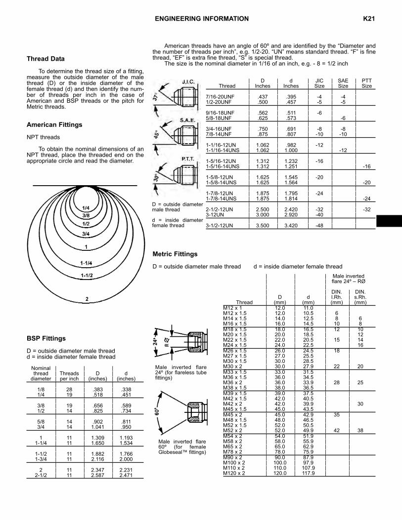
ENGINEERING INFORMATION K21
Thread Data
To determine the thread size of a fitting,measure the outside diameter of the malethread (D) or the inside diameter of thefemale thread (d) and then identify the num-ber of threads per inch in the case ofAmerican and BSP threads or the pitch forMetric threads.
American Fittings
NPT threads
To obtain the nominal dimensions of anNPT thread, place the threaded end on theappropriate circle and read the diameter.
BSP Fittings
D = outside diameter male threadd = inside diameter female thread
Nominal | | |thread | Threads | D | d
diameter | per inch | (inches) | (inches)| | |
1/8 | 28 | .383 | .3381/4 | 19 | .518 | .451
| | |3/8 | 19 | .656 | .5891/2 | 14 | .825 | .734
| | |5/8 | 14 | .902 | .8113/4 | 14 | 1.041 | .950
| | |1 | 11 | 1.309 | 1.193
1-1/4 | 11 | 1.650 | 1.534| | |
1-1/2 | 11 | 1.882 | 1.7661-3/4 | 11 | 2.116 | 2.000
| | |2 | 11 | 2.347 | 2.231
2-1/2 | 11 | 2.587 | 2.471
American threads have an angle of 60º and are identified by the “Diameter andthe number of threads per inch”, e.g. 1/2-20. “UN” means standard thread. “F” is finethread, “EF” is extra fine thread, “S” is special thread.
The size is the nominal diameter in 1/16 of an inch, e.g. - 8 = 1/2 inch
Metric Fittings
D = outside diameter male thread d = inside diameter female thread
| D | d | JIC | SAE | PTTThread | Inches | Inches | Size | Size | Size
| | | | |7/16-20UNF | .437 | .395 | -4 | -4 |1/2-20UNF | .500 | .457 | -5 | -5 |
| | | | |9/16-18UNF | .562 | .511 | -6 | |5/8-18UNF | .625 | .573 | | -6 |
| | | | |3/4-16UNF | .750 | .691 | -8 | -8 |7/8-14UNF | .875 | .807 | -10 | -10 |
| | | | |1-1/16-12UN | 1.062 | .982 | -12 | |1-1/16-14UNS | 1.062 | 1.000 | | -12 |
| | | | |1-5/16-12UN | 1.312 | 1.232 | -16 | |1-5/16-14UNS | 1.312 | 1.251 | | | -16
| | | | |1-5/8-12UN | 1.625 | 1.545 | -20 | |1-5/8-14UNS | 1.625 | 1.564 | | | -20
| | | | |1-7/8-12UN | 1.875 | 1.795 | -24 | |1-7/8-14UNS | 1.875 | 1.814 | | | -24
| | | | |2-1/2-12UN | 2.500 | 2.420 | -32 | | -323-12UN | 3.000 | 2.920 | -40 | |
| | | | |3-1/2-12UN | 3.500 | 3.420 | -48 | |
D = outside diametermale thread
d = inside diameterfemale thread
| | | Male inverted| | | flare 24º – RØ| | || | | DIN. | DIN.| D | d | l.Rh. | s.Rh.
Thread | (mm) | (mm) | (mm) | (mm)M12 x 1 | 12.0 | 11.0 | |M12 x 1.5 | 12.0 | 10.5 | 6 |M14 x 1.5 | 14.0 | 12.5 | 8 | 6M16 x 1.5 | 16.0 | 14.5 | 10 | 8M18 x 1.5 | 18.0 | 16.5 | 12 | 10M20 x 1.5 | 20.0 | 18.5 | | 12M22 x 1.5 | 22.0 | 20.5 | 15 | 14M24 x 1.5 | 24.0 | 22.5 | | 16M26 x 1.5 | 26.0 | 24.5 | 18 |M27 x 1.5 | 27.0 | 25.5 | |M30 x 1.5 | 30.0 | 28.5 | |M30 x 2 | 30.0 | 27.9 | 22 | 20M33 x 1.5 | 33.0 | 31.5 | |M36 x 1.5 | 36.0 | 34.5 | |M36 x 2 | 36.0 | 33.9 | 28 | 25M38 x 1.5 | 38.0 | 36.5 | |M39 x 1.5 | 39.0 | 37.5 | |M42 x 1.5 | 42.0 | 40.5 | |M42 x 2 | 42.0 | 39.9 | | 30M45 x 1.5 | 45.0 | 43.5 | |M45 x 2 | 45.0 | 42.9 | 35 |M48 x 1.5 | 48.0 | 46.5 | |M52 x 1.5 | 52.0 | 50.5 | |M52 x 2 | 52.0 | 49.9 | 42 | 38M54 x 2 | 54.0 | 51.9 | |M58 x 2 | 58.0 | 55.9 | |M65 x 2 | 65.0 | 62.9 | |M78 x 2 | 78.0 | 75.9 | |M90 x 2 | 90.0 | 87.9 | |M100 x 2 | 100.0 | 97.9 | |M110 x 2 | 110.0 | 107.9 | |M120 x 2 | 120.0 | 117.9 | |
Male inverted flare24º (for flareless tubefittings)
Male inverted flare60º (for femaleGlobeseal™ fittings)


