+ All Categories
Home > Documents > Code Water Distribution Version 03

Code Water Distribution Version 03

Date post: 16-Feb-2018
Category:
Upload: miguel-abueg
View: 220 times
Download: 0 times
Share this document with a friend
63
 Version 3.0 ABU DHABI DISTRIBUTION COMPANY AL AIN DISTRIBUTION COMPANY ABU DHABI COMPANY FOR SERVICING REMOTE AREAS THE WATER DISTRIBUTION CODE Version 3.0 July 2010 Approved by: The Regulation and Supervision Bureau for the Water, Wastewater and Electricity Sector in the Emirate of Abu Dhabi
Transcript

7/23/2019 Code Water Distribution Version 03

http://slidepdf.com/reader/full/code-water-distribution-version-03 1/62

  Version 3.0

ABU DHABI DISTRIBUTION COMPANY

AL AIN DISTRIBUTION COMPANY

ABU DHABI COMPANY FOR SERVICING REMOTE AREAS

THE WATER DISTRIBUTION

CODE

Version 3.0

July 2010

Approved by:

The Regulation and Supervision Bureau for the Water, Wastewaterand Electricity Sector in the Emirate of Abu Dhabi

7/23/2019 Code Water Distribution Version 03

http://slidepdf.com/reader/full/code-water-distribution-version-03 2/62

  Version 3.0

THE WATER DISTRIBUTION CODE

PREFACE................................................................................................................................................2  

CHAPTER 1  GLOSSARY AND DEFINITIONS...........................................................................4 

CHAPTER 2  WATER DISTRIBUTION GENERAL CONDITIONS......................................12 

1.  INTRODUCTION...............................................................................................................................12 2.  SCOPE.................................................................................................................................................12  3.  UNFORESEEN CIRCUMSTANCES................................................................................................12 4.  THE WATER DISTRIBUTION CODE REVIEW PANEL..............................................................12 5.  COMMUNICATION BETWEEN DISCOs AND USERS ...............................................................13 6.  MISCELLANEOUS ...........................................................................................................................13 7.  OWNERSHIP OF PLANT AND/OR APPARATUS........................................................................13 

CHAPTER 3  WATER DISTRIBUTION PLANNING CODE...................................................15 

1.  GENERAL INTRODUCTION...........................................................................................................15 2.  OBJECTIVE........................................................................................................................................16  3.  SCOPE.................................................................................................................................................16  4.  PLANNING PROCEDURES AND DATA TRANSFER .................................................................16 

 APPENDIX A - WATER PLANNING DATA........................................................................ ............20  APPENDIX B - DISCO NETWORK DATA......................................................................................21  APPENDIX C  – TECHNICAL PARAMETERS AND DESIGN GUIDELNES................................22  APPENDIX D  – FIRE FIGHTING REQUIREMENTS....................................................................31 

1) Water Distribution System ..................................................................................................................31 2)  Internal Firefighting & Suppression Systems.....................................................................................32 

CHAPTER 4  WATER DISTRIBUTION CONNECTION CODE ............................................33 

1.  GENERAL INTRODUCTION...........................................................................................................33 2.  OBJECTIVE........................................................................................................................................33  3.  SCOPE.................................................................................................................................................33  4.  PROCEDURE.....................................................................................................................................33 5.  CONNECTION...................................................................................................................................33 6.  TECHNICAL, DESIGN AND OPERATIONAL CRITERIA ..........................................................34 7.  SITE RELATED CONDITIONS .......................................................................................................35 

 APPENDIX A - PROCEDURE TO BE USED IN THE PREPARATION OF SITE RESPONSIBILITY SCHEDULES................................................ .....................................................39  APPENDIX B - NON-EXHAUSTIVE LIST OF APPARATUS TO BE INCLUDED ON

OPERATION DIAGRAMS................................................................................................................42 

CHAPTER 5  WATER DISTRIBUTION OPERATING CODE................................................44 

1.  GENERAL INTRODUCTION...........................................................................................................44 2.  GENERAL SCOPE.............................................................................................................................44 3.  DEMAND FORECASTS INCLUDING OUTAGE PLANNING.....................................................44 4.  SAFETY CO-ORDINATION ............................................................................................................46 5.  WATER QUALITY............................................................................................................................47 6.  OPERATIONAL LIAISON................................................................................................................48 7.  CONTINGENCY PLANNING AND PROCEDURES .....................................................................50 8.  START-UP AND SHUT-DOWN PROCEDURES ...........................................................................52 9.   NUMBERING AND NOMENCLATURE OF PLANT....................................................................53 

 APPENDIX A - TYPICAL CONTINGENCY PLAN .........................................................................55 

7/23/2019 Code Water Distribution Version 03

http://slidepdf.com/reader/full/code-water-distribution-version-03 3/62

  Version 3.0

PREFACE

The Water Distribution Code

The Water Distribution Code has been developed to reflect the organisation of the

Abu Dhabi Water and Electricity Sector into the following Entities:

a) Desalinated Water Producers

 b) The Abu Dhabi Water and Electricity Company (ADWEC), the single buyer

and seller of Desalinated Water Producers capacity and output

c) A Transmission Operating Company and a Scheduling and Despatch Company

(TRANSCO) 

d) Distribution Companies, initially Abu Dhabi Distribution Company, Al Ain

Distribution Company and Abu Dhabi Company For Servicing Remote Areas(DISCOs)

e) The Abu Dhabi Company For Servicing Remote Areas is responsible for

well-field production and some Desalinated Water Production.

f) Customers 

The Code  is designed to allow operation of the Abu Dhabi Water Distribution

System and provide controlled connection arrangements at the entry and exit points to

the Water Distribution System between directly connected Water Producers, other

Distribution Companies (other connected DISCOs) and High Consumption 

Customers  respectively. In this Code, Users  are defined as  Water Producersconnected directly to the DISCO, other connected DISCOs and Customers with high

consumption levels.

The Water Distribution Code is divided into the following Chapters:

1. Glossary and Definitions  that describe certain words and terms used

in the Code;

2. Water Distribution General Conditions  that describe provisions of

general application and include requirements and arrangements not

otherwise referred to in the Code including the role and constitution of

The Water Distribution Code Review Panel;

3. A Water Distribution Planning Code which provides generally for

the supply of water demand data by Users  in order for DISCOs  to

undertake the planning and development of the Water Distribution

System;

4. A Water Distribution Connection Code  which describes the

connection conditions criteria which must be complied with at

7/23/2019 Code Water Distribution Version 03

http://slidepdf.com/reader/full/code-water-distribution-version-03 4/62

  Version 3.0

Connection Sites and by Users already connected to or seeking new or

modified connections with the Water Distribution System;

5. A Water Distribution Operating Code, which is split into a number

of sections. These principally deal with the forecasting of short and

medium term water Demand, production requirements (for routine

operation and outage planning), safety co-ordination, maintenance ofwater quality, operational liaison, contingency planning, start-up and

shut-down of plant and numbering and nomenclature of plant and

apparatus;

TRANSCO has produced a Water Transmission Code, approved by the Regulation

and Supervision Bureau  for the Water and Electricity Sector, which defines the

technical aspects of the working relationship between TRANSCO  and those

connected to the TRANSCO Transmission System. TRANSCO also has a duty to

manage and control Scheduling and Despatch of potable water to balance availability

with Demand at strategic locations in the Total System.

The Water Transmission Code makes provision for abstraction of groundwater fromwell-fields to be included within the definition of a Water Producer. Water

Producers are generally connected with the water transmission system and the

transmission system in turn is connected with water distribution systems. In some

cases Water Producers supply DISCOs  direct. All Customers are supplied and

 billed by the DISCOs.

7/23/2019 Code Water Distribution Version 03

http://slidepdf.com/reader/full/code-water-distribution-version-03 5/62

  Version 3.0

CHAPTER 1 GLOSSARY AND DEFINITIONS

In the Water Distribution Code the following words and expressions shall, unless

the subject matter or context otherwise requires or is inconsistent therewith, bear the

following meanings:

ADWEC The Abu Dhabi Water and Electricity Company

(ADWEC), the single buyer and seller of

Desalinated Water Producers capacity and output

Bureau The Regulation and Supervision Bureau  for the

Water and Electricity Sector .

Completion Date Has the meaning set out in the Connection

Agreement with each User.

Connection Agreement An agreement setting out terms relating to a

connection with the DISCO Distribution System (excluding any such agreement with TRANSCO).

Connection Point A Water Distribution System  connection or

 junction with a User System.

Connection Site A DISCO Site or User Site 

Customer Any person who has an agreement with a DISCO 

for the provision of potable water.

Customer Categories The categorisation of Customers  into different

 bands based on their indicative water consumptionand main purpose of use and tariff arrangements.

Customer Water Rationing Reducing the availability of potable water to a

User’s site, either on a reduced pressure or “time

supply” band or disconnecting a Customer  in a

manner agreed between a DISCO and a User 

Demand The required potable water needed to meet

Customer use, adjusted to take into account Water

Demand Management policies, which may include

water conservation, efficiencies of use and water

leakage.

Demand Control  Any or all of the methods of achieving a Demand 

reduction.

Despatch Issue by the Water Control Centre of instructions

for pumping/storage plant  to meet Demand  within

the Scheduling  and Despatch  Parameters as

7/23/2019 Code Water Distribution Version 03

http://slidepdf.com/reader/full/code-water-distribution-version-03 6/62

  Version 3.0

referred to in the Transmission Licence.

Determinant A Water Quality  parameter which is the result of

direct in-situ measurement or testing of a water

sample. Determinants  include test results for pH,

Electrical Conductivity, Chlorine Residual,

Hardness, Alkalinity, Chlorides and othersubstances.

Directly Connected Water

Producers

Water Producers having a direct connection to the

Water Distribution System.

DISCO A holder of a Distribution Licence.

DISCO Site Means a site owned (or occupied pursuant to a lease,

licence or other agreement) by the DISCO in which

there is a Connection Point.

Distribution Entry Point A Connection Point  at which a DirectlyConnected  Water Producer  or TRANSCO  or

DISCO is directly connected to a DISCO 

Distribution System through which water can enter

the DISCO’s system

Distribution Exit Point A Connection Point  at the exit from the DISCO

Distribution System. 

Distribution System The system consisting (wholly or mainly) of water

 pipes and associated plant which are owned or

operated by a DISCO and used for the distribution

of potable water to the point of delivery to

Customers, or other Users.

Flow Meter  A device used for measurement of water flow which

is either read manually or recorded remotely. 

Good Industry Practice  In relation to any undertaking and any

circumstances, the exercise of that degree of skill,

diligence, prudence and foresight which would

reasonably and ordinarily be expected from a skilled

and experienced operator engaged in the same type

of undertaking under the same or similarcircumstances;

High Consumption Customer A  Customer, generally metered, whose demand is

equal to or exceeds the stated amount of Paragraph 5

a) of Condition 27 of the DISCOs Licence such as

commercial, retail, industrial and other special

Customers. Also included in this category are other

high consumption Customers, sometimes metered,

7/23/2019 Code Water Distribution Version 03

http://slidepdf.com/reader/full/code-water-distribution-version-03 7/62

  Version 3.0

with a connection pipe > 50 mm diameter (or

multiple connection pipes each more than 50 mm

diameter).

Law Law No 2 of 1998 Concerning the Regulation of the

Water and Electricity Sector in the Emirate of Abu

Dhabi

Licence Any Licence granted to a DISCO or a User, under

Article 82 of the Law.

Licence Standards Those standards set out or referred to in Condition

254 of the Distribution License.

Low Consumption Customer A Customer whose demand is beneath the stated

amount of Paragraph 5a) of Condition 27 of the

DISCOs Licence

Modification Any actual or proposed replacement, renovation,modification, alteration or construction by or on

 behalf of a User  or DISCO  to either that User's 

Plant or Apparatus or DISCO’s Plant or Apparatus,

or the manner of its operation which has or may

have a material effect on a DISCO or a User, at a

 particular Connection Site.

Network Data The data to be provided by a DISCO  to Users  in

accordance with the Water Distribution Planning

Code, as listed in Appendix B to the Water

Distribution Planning Code

Network Security Standard A License Standard for planning and development

of the water network which employs best practice

 planning tools and procedures to ensure that

 pipelines, pumping stations, and reservoirs have

sufficient capacity to meet all reasonable demand

with view to the risk of interruption and

contingencies.


Operating Manuals A manual that describes operation, maintenance

needs and maintenance requirements  for Potable

Water Plant or Apparatus,  for the purposes ofmaintaining secure day to day operation.

Operation Diagrams Diagrams which are a schematic representation of

the Potable Water Plant and the connections layout

at a Connection Site. 

Operational Planning Planning through various timescales the matching of

Water Production  output with Demand  together

7/23/2019 Code Water Distribution Version 03

http://slidepdf.com/reader/full/code-water-distribution-version-03 8/62

  Version 3.0

with a reserve of production capacity to provide a

margin, taking into account outages of certain

Water Production Units or parts of the TRANSCO

Water Trunk Mains System and of parts of Water

Distribution Systems carried out to achieve, so far

as possible, the standards of security set out in the

DISCO Licence.

Potable Water Plant  A generic term that describes the plant used in raw

water abstraction, water production, water

treatment, transmission and distribution that may be

 both above and below ground.

Preface The Preface  to the Water Distribution Code 

(which does not form part of the Code and therefore

is not binding).

Pressure Transient A rapid change (+ or -) in water pressure within a

closed pipe network due to Pump  Start-Up  andShut-Down and Valve operation.

Pump Plant that mechanically raises water pressure within

a closed pipe network for the purposes of producing

water flow along the pipe.

Pumping Head The variable pressure, generally referred to in

metres of water, which is exerted on the pipe work

and pumping plant by operation of that pumping

 plant. The operating pressures vary throughout the

Water Trunk Mains System  or Distribution

System.

Record Drawings Sections and plans (usually to different scales) of a

User’s Potable Water Plant  that describe in detail

the above and below ground installation after

construction.

Responsible Engineer/Operator A person nominated by a User to be responsible for

System control.

Responsible Manager A manager who has been duly authorised by a User 

or DISCO to sign Site Responsibility Schedules on behalf of that User or DISCO.

Safety Co-ordinator A person or persons nominated by a DISCO  and

each User to be responsible for the co-ordination of

safety precautions at each Connection Point when

work (which includes testing) is to be carried out on

a system.

7/23/2019 Code Water Distribution Version 03

http://slidepdf.com/reader/full/code-water-distribution-version-03 9/62

  Version 3.0

Safety Rules The rules of a DISCO or a User that seek to ensure

that persons working on plant to which the rules

apply are safeguarded from hazards arising from the

system.

Scheduling The process of compiling and issuing a potable

water schedule, as set out in Water Scheduling andDespatch Code of  the Transmission Code (Water).

Security Standard A coordinated set of criteria and methodologies

which Licensees shall use in the planning and

development of their Water Distribution Systems.

Shut-Down The condition of pumping plant when the motor is

static and the system becomes depressurised over

time once gravity equilibrium is achieved.

Site Common Drawings Drawings prepared for each Connection Site which

incorporate Connection Site  pipe layout, pumping plant, local storage and associated apparatus.

Site Responsibility Schedule A schedule containing the information and prepared

on the basis of the provisions set out in the Water

Distribution Connection Code.

Standby Generation Standby power supply capability for Potable Water

Plant (generally pumping stations remote from

Power Stations) in case of power cuts.

Start-Up The action of bringing pumping plant from

Shutdown into operation.

Supply Regulations Regulations  issued by the Bureau pursuant to

Article 62 of the Law.

Tariff Customer A Customer, generally comprising domestic

 premises with a connection pipe less than 50 mm

diameter (or multiple connection pipes each less

than 50 mm diameter), usually metered and supplied

on a tariff basis. Tariff Customers are not subject

to this Code.

TRANSCO The Abu Dhabi Transmission and Despatch

Company, operating the Water Trunk Mains

System,  associated Potable Water Plant  and

undertaking central Scheduling  and Despatch

functions (at the Water Control Centre).

Transmission Code (Water) The Code required under the terms of the

Transmission Licence  to be produced and

7/23/2019 Code Water Distribution Version 03

http://slidepdf.com/reader/full/code-water-distribution-version-03 10/62

7/23/2019 Code Water Distribution Version 03

http://slidepdf.com/reader/full/code-water-distribution-version-03 11/62

  Version 3.0

10 

from a new User in an application for a Connection

Agreement.

Water Producer An entity producing potable water under a

desalination Licence or from well-field abstractions

Water Quality The quality of potable water defined by reference tominimum acceptable standards that relate to bacteria

(hygienic quality), chemical composition, health

related characteristics, aggressive effects, odour,

taste and others as prescribed in the Water Quality

Regulations.

Water Trunk Mains System  The network of trunk mains, pumping stations and

associated Potable Water Plant that constitutes the

water transmission system operated by TRANSCO. 

Water Supply Regulations  Regulations issued by the Bureau under Article 62

of the Law. 

7/23/2019 Code Water Distribution Version 03

http://slidepdf.com/reader/full/code-water-distribution-version-03 12/62

  Version 3.0

11 

Construction and Interpretation

In the Water Distribution Code:

a) A table of contents, a Preface and headings are inserted for convenience only

and shall be ignored in construing the Water Distribution Code; 

 b) Unless otherwise required, all references to a particular paragraph, sub-

 paragraph, Appendix or Schedule shall be a reference to that paragraph, sub-

 paragraph Appendix or Schedule in or to that part of the Water Distribution

Code in which the reference is made;

c) Unless otherwise required, the singular shall include the plural and vice versa,

references to any gender shall include all other genders and references to

 persons shall include any individual and any other entity, in each case whether

or not having a separate legal personality;

d) References to the words “include” or “including” are to be construed without

limitation to the generality of the preceding words;

e) Unless there is something in the subject matter or the context which is

inconsistent, any reference to the Law  or any Article of or Schedule to, or

other provision of the Law shall be construed as including a reference to any

Modification, extension or re-enactment thereof then in force and to all

instruments, orders and regulations then in force and made under or deriving

validity from the relevant Law;

f) References to “in writing” or “written” include word processing, printing, fax

and other modes of reproducing and transmitting words and text;

g) Where the Glossary and Definitions refers to any word or term which is more particularly defined in a part of the Water Distribution Code, the definition

in that part of the Water Distribution Code, will prevail over the definition in

the Glossary and Definitions in the event of any inconsistency;

h) A cross-reference to another document or part of Water Distribution Code 

shall not impose any additional, further or co-existent obligation or confer any

additional, further or co-existent right in the part of the text where such cross-

reference is contained; and

i) Nothing in the Water Distribution Code is intended to or shall derogate from 

DISCO’s or User’s statutory or Licence obligations.

7/23/2019 Code Water Distribution Version 03

http://slidepdf.com/reader/full/code-water-distribution-version-03 13/62

  Version 3.0

12 

CHAPTER 2 WATER DISTRIBUTION GENERAL CONDITIONS

1.  INTRODUCTION

The Water Distribution General Conditions (WDGC) contain provisions which are of

general application to all provisions of the Water Distribution Code.  Their objective

is to ensure, to the extent possible, that the various sections of the Water

Distribution Code work together and work in practice for the benefit of all Users.

2.  SCOPE

The General Conditions apply to all Users including the relevant DISCO.

3.  UNFORESEEN CIRCUMSTANCES

If circumstances arise which the provisions of the Water Distribution Code have not

foreseen, the DISCO shall, to the extent reasonably practicable in the circumstances,

consult promptly and in good faith all affected Users in an effort to reach agreement

as to what should be done. If agreement between the DISCO and those Users as to

what should be done cannot be reached in the time available, the DISCO  shall

determine what is to be done. Wherever the DISCO makes a determination, it shall

do so having regard, wherever possible, to the views expressed by Users and, in any

event, to what is reasonable in all the circumstances. Each User shall comply with all

instructions given to it by the DISCO following such a determination provided that

the instructions are consistent with the then current technical parameters of the

 particular User's System registered under the Water Distribution Code. The DISCO 

shall promptly refer all such unforeseen circumstances and any such determination to

the Panel for consideration.

4.  THE WATER DISTRIBUTION CODE REVIEW PANEL

The DISCOs  shall jointly establish and maintain a single Panel, which shall be a

standing body to carry out the functions referred to below.

The Panel shall:

i)  Keep the Water Distribution Code and its working under review;

ii)  review all suggestions for amendments to the Water Distribution Code

which the Bureau  or any User  may wish to submit to the DISCOs  for

consideration by the Panel from time to time;

iii)  Publish recommendations as to amendments to the Water DistributionCode that each DISCO or the Panel feels are necessary or desirable and the

reasons for the recommendations;

iv)  Issue guidance in relation to the Water Distribution Code and its

implementation, performance and interpretation when asked to do so by any

User; and

v)  Consider what changes are necessary to the Water Distribution Code

arising out of any unforeseen circumstances referred to it by each DISCO.

7/23/2019 Code Water Distribution Version 03

http://slidepdf.com/reader/full/code-water-distribution-version-03 14/62

  Version 3.0

13 

The Panel shall consist of:

i)  A Chairman and up to 3 members appointed by the DISCOs 

ii)  A person appointed by the Bureau 

iii)  A maximum of 1 person appointed on behalf of Water Producers directly

connected to a DISCO system

iv)  A person appointed by the Abu Dhabi Water and Electricity Company, and

the following members:

v)  A person appointed on behalf of High Consumption Customers 

vi)  A person appointed on behalf of the Low Consumption Customers;

each of whom shall be appointed as set out below.

The Panel shall establish and comply at all times with its own rules and procedures

relating to the conduct of its business, which shall be approved by the Bureau.

The DISCO shall consult in writing all Users and representatives of Customers who

are liable to be materially affected in relation to all proposed amendments to the

Water Distribution Code and shall submit all proposed amendments to the Panel for

discussion prior to such consultation.

5.  COMMUNICATION BETWEEN DISCOS AND USERS

Unless otherwise specified in the Water Distribution Code, the methods of

operational communication and data transfer shall be agreed between the DISCO and

Users from time to time.

6.  MISCELLANEOUS

Data and notices to be submitted to the DISCOs under the Water Distribution Code

(other than delivery of data which is the subject of a specific requirement of the

Water Distribution Code) shall be delivered in writing either by hand, sent by

registered pre-paid post, or communicated by telex or facsimile transfer.

Communications referred to above, shall be addressed to the Responsible Manager 

of either a DISCO or a User at the addresses previously notified to all parties.

7.  OWNERSHIP OF PLANT AND/OR APPARATUS

References in the Water Distribution Code to Plant and/or Apparatus of a User include Plant and/or Apparatus used by or on behalf of a User under any agreement

with a third party.

7/23/2019 Code Water Distribution Version 03

http://slidepdf.com/reader/full/code-water-distribution-version-03 15/62

  Version 3.0

14 

8. DUTY OF GOOD FAITH AND STANDARD OF CONDUCT

Each party to the Code shall at all times in its dealings with the other parties to this

Code:

(a) Act in good faith;

(b) Act in accordance with Good Industry Practice.

9. CODE RESPONSIBILITIES

The  Water Distribution Code sets out procedures and principles governing  the

relationship between the DISCO  and all Users of the DISCO Water Distribution

System as required by the relevant sections of the Water Distribution Code.

7/23/2019 Code Water Distribution Version 03

http://slidepdf.com/reader/full/code-water-distribution-version-03 16/62

  Version 3.0

15 

CHAPTER 3 WATER DISTRIBUTION PLANNING CODE

1.  GENERAL INTRODUCTION

The Water Distribution Planning Code (WDPC) specifies the criteria and procedures

to be applied by a DISCO  in planning and development of the DISCO  Water

Distribution System  and to be taken into account by Users in the planning and

development of their own needs. It details information to be supplied by Users to a

DISCO, and certain information to be made available by a DISCO to Users.

Development of the DISCO  Water Distribution System, involving network

expansion (including new Mains) and its reinforcement or extension, will arise for a

number of reasons including, but not limited to:

i)   New development and therefore increased water Demand by Users already

connected to a DISCO Water Distribution System;

ii)  Introduction of a new Connection Site or the Modification of an existing

Connection Site between a User and a DISCO Water Distribution

System;

iii)  Cumulative changes in both Low Consumption Customer and High 

Consumption Customer water use, improved Customer levels of service

and security of Customer supply;

iv)  The cumulative effect of a number of such developments referred to above

 by one or more Users.

Accordingly, the expansion, reinforcement or extension of the DISCO  WaterDistribution System may involve work:

i)  At a Customer connection which is also a Connection Site where User's

 plant is connected to the DISCO Water Distribution System;

ii)  On distribution mains which join that Connection Site  to the DISCO 

Water Distribution Main System;

iii)  On distribution mains at points remote from that Connection Site; or

iv)  At the interface between DISCOs 

The time required for the planning and development of a DISCO Water Distribution

System will depend on the type and extent of the necessary expansion, reinforcementand/or extension work. Other influences may include the need or otherwise for local

 planning consent, the associated possibility of the need for an independent planning

determination and the degree of complexity in undertaking the new work while

maintaining satisfactory security and quality of water supply on the existing DISCO 

Water Distribution System.

7/23/2019 Code Water Distribution Version 03

http://slidepdf.com/reader/full/code-water-distribution-version-03 17/62

  Version 3.0

16 

2.  OBJECTIVE

The objectives of the WDPC are:

i)  To promote DISCO/User  interaction in respect of any proposed waterservices development on the User System  which may impact on the

discharge capacity or the network layout of the DISCO  Water

Distribution Main System;

ii)  To formalise the exchange of information on water Demand and;

iii)  To provide sufficient information for a User to plan and develop his own

system and assess connection opportunities.

iv)  To provide safe, reliable, and efficient water supply facilities by adopting

 planning standards.

3.  SCOPEThe Users to whom the Water Distribution Planning Code (WDPC) apply are those

who use or intend to use the DISCO Water Distribution System, as follows:

i)  High Consumption Customers. 

ii)  Other connected DISCO 

iii)  Directly Connected Water Producers 

Low Consumption  Customers  will become bound by their own Connection

Agreement on successful acceptance of their respective application to receive potable

water supply and therefore are not Users under this Code.

4.  PLANNING PROCEDURES AND DATA TRANSFER

4.1 General

The means by which Users  and potential Users  of a DISCO  Water Distribution

System are able to investigate connection to and use of the system comprises two

distinct parts, namely:

i)  A planning statement, prepared by the DISCO which is available  on

request; and

ii)  An offer, in accordance with the Licence, by the DISCO  to enter into a

Connection Agreement  for connection to the DISCO  Water

Distribution System.

7/23/2019 Code Water Distribution Version 03

http://slidepdf.com/reader/full/code-water-distribution-version-03 18/62

  Version 3.0

17 

4.2 Provision of Water Planning Data For Connection

4.2.1  Demand Data

This section of the WDPC specifies the information required from Users, other than Directly Connected Water Producers, by the DISCO in order to ensure adequate

technical provision is made for new supplies or increases in the Demands of  existing

supplies. The information required is termed Water Planning Data and detailed in

Appendix A.

At the time a User applies for a Connection Agreement, the User shall submit to the

DISCO, the Water Planning Data.

Subsequent to receiving an offer and entering into a Connection Agreement, the 

User shall submit to the DISCO any changes to the Water Planning Data previously

submitted. Similarly, updated Water Planning Data, including validated actual

values and updated estimates for the future shall be submitted subsequent to a

connection being made.

An existing User  proposing a new Connection Site  shall similarly provide data

within the requirements of the WDPC.

4.2.2 Data Provided by Directly Connected Water Producers

The Water Distribution System that is developed by a Directly Connected Water

Producer  must be developed in conjunction with that of a Directly Connected

Water Producer, in order to ensure compatibility between systems. DirectlyConnected Water Producers  shall provide the DISCO  with Planning Data  that

includes data on existing and proposed pump and pressure specifications and Water

Quality  equipment that supplies potable water to the Water Distribution System.

The Water Planning Data shall be provided at the same time as the application and

confirmed and updated on entering into a Connection Agreement and subsequent to

the connection being made. Any subsequent changes shall also be advised to the

DISCO.

4.3 Offer of Terms for Connection

The completed User application form for a Connection Agreement will include:

i)  A description of the new plant to be connected to the Water Distribution

System or of the Modification  relating to the Users  plant  already

connected to the system;

ii)  The Water Planning Data as listed in Appendix A WDPC; and

iii)  The desired Completion Date of the proposed User Development.

The completed application form will be sent to the DISCO.

7/23/2019 Code Water Distribution Version 03

http://slidepdf.com/reader/full/code-water-distribution-version-03 19/62

  Version 3.0

18 

Any offer of a Connection Agreement made by the DISCO, must be accepted by the

applicant User  within the period stated in the offer, after which the offer

automatically lapses. Acceptance of the offer renders the DISCO works relating to

that User Development, reflected in the offer, committed and binds both parties to the

terms of the offer. Within 28 days (or such longer period as the DISCO may agree in

any particular case) of acceptance of the offer the User  shall confirm the WaterPlanning Data  pertaining to the User  Development, as listed in Appendix A of

WDPC.

Before entering into a Connection Agreement it will be necessary for the DISCO to

 be satisfied that the Users  system at the boundary with the Water Distribution

System  will comply with all appropriate requirements of the Water Distribution

Code. 

The User  installation shall comply with the principles contained in the Supply

Regulations.

4.4  Planning Statement

On request the DISCO  will prepare a statement detailing present and future

distribution system network arrangements, capacities and any other restrictions that

may limit water supplies. The statement will be prepared by the DISCO within 28

days after the date of receipt of the request or the date on which the DISCO receives

agreement from the person making the request to pay any fee.

4.5 Information to be provided to Users

Where the DISCO  has received from a User  any information or Demand  data, or

where the DISCO  proposes to make changes to the Water Distribution System 

which may impact upon the User’s system, the DISCO shall notify the User, subjectto any confidentiality provisions.

The DISCO will also make available to Users relevant details of its System. This is

termed DISCO Network Data as referred to in Appendix B of the WDPC.

4.6 Network Security Standards

The DISCO shall take into consideration the following Network Security Standards 

in the planning and development of the Water Distribution System:

1-   Network Capacity Planning Criteria as outlined in Clause 4.6.1 which set the

general guidelines for the technical design criteria and performancerequirements for the planning and development of the Water Distribution

System.

2-  Performing network risk analysis to the existing network and for major system

developments to determine if the risk of interruptions is in accordance with the

Security Standard risk criteria as defined in Clause 3 (planning tools) of

Appendix B of the Planning Code.

7/23/2019 Code Water Distribution Version 03

http://slidepdf.com/reader/full/code-water-distribution-version-03 20/62

  Version 3.0

19 

3-  Contingency planning and procedures as outlined in the Water Distribution

Operation Code with emphasis on areas not meeting the Security Standard risk

criteria.

4.6.1 Network Capacity Planning

This section sets out the technical design criteria guidelines and performancerequirements for the Water Distribution Systems. Network Capacity Planning is

divided into three parts: Technical Parameters and Design Guidelines, Sizing of

distribution system main components and Planning Tools as set in Appendix C and

for fire fighting requirements Appendix D of Chapter 3 (Water Distribution Planning

Code).

4.7 Water Demand Management

Longer term and strategic management of water Demand  and the application of

relevant policies and strategies is not detailed in this Code but will be determined by

the Bureau. 

7/23/2019 Code Water Distribution Version 03

http://slidepdf.com/reader/full/code-water-distribution-version-03 21/62

  Version 3.0

20 

APPENDIX A - WATER PLANNING DATA

1. Demand Data

Water Planning Data  (water Demand  data) is required for new or modified

connection applications from Users, for the DISCO to provide planning statements to

Users.  Water Planning Data shall be submitted in accordance with the WDPC.

This data shall include forecast or validated actual water Demand  over at least the

next three years. More particularly, the average daily water Demand during the week

of maximum consumption in the year and the average annual daily consumption, both

in MIG/D should be provided. The water planning data shall make due allowance for

operational use of the system, system network efficiencies, losses within the system

and where applicable, current Demand Control policies that may be in place.

Ml/d is mega litres/day (106 litres/day)

Conversions: 1 Ml/d = 41.67 m3/hour (cubic metres/hour)

1 MIG/D = 4.55 Ml/d

(million imperial gallons per day)

The DISCO shall maintain a database of Water Planning Data of historic and three

year forecast Demand data for Users and Low Consumption Customers. Such data

shall be maintained on a network node by node basis.

2. Data to be Provided by Directly Connected Water Producers

The following data shall be provided:

i)  Existing and proposed capacities, flow rates and pressure variations;

ii)  Pump specifications;

iii)  Storage tank volumes including top and bottom water levels and usable

storage;

iv)  Water Quality equipment.

7/23/2019 Code Water Distribution Version 03

http://slidepdf.com/reader/full/code-water-distribution-version-03 22/62

  Version 3.0

21 

APPENDIX B - DISCO NETWORK DATA

Both the  DISCO and Users may need to undertake hydraulic analysis and in more

complex cases, numerical modelling of the Water Distribution System  in order to

check the pipe network and pumping capacities that feed potable water to the Water

Distribution System. Users may seek to confirm hydraulic feasibility in principle

 before an application is submitted to modify an existing connection or expand thesystem with a new connection. Network Data  made available by DISCO  for

inspection will include the following;

i)   Network node data, normal range of operating pressures

ii)  Operating and design flow rates

iii)  Pipe materials, age (hence friction factor) and lengths

iv)  Variable head storage reservoir levels and storage volumes

v)  Pipe diameters

vi)  Pump type and characteristics (time switched, level controlled or pressurecontrolling)

vii)  Control valve settings/characteristics

The DISCO shall maintain a database of Network Data of the existing and planned

Water Distribution System. Network Data shall incorporate all data as identified

above, extending from the Distribution Entry to Exit Points and include connections

to High Consumption and Low Consumption Customers.

The DISCO shall also maintain a database of all Water Quality monitoring,

sampling and dosing points on the Water Distribution System and retain a registerof Water Quality results data. 

The DISCO shall also maintain data on any Directly Connected Water Producers 

that shall include existing and proposed pumping plant specifications and Water

Quality treatment equipment.

7/23/2019 Code Water Distribution Version 03

http://slidepdf.com/reader/full/code-water-distribution-version-03 23/62

  Version 3.0

22 

APPENDIX C – TECHNICAL PARAMETERS AND DESIGN GUIDELNES

The following are the technical parameters and design guidelines used in sizing the

distribution system main components.

i) Demand Criteria

Demand is the required potable water needed to meet Customer use, adjusted to take

into account Water Demand Management policies, which may include water

conservation efficiencies of use and water leakage. However other demand criteria are

generally applied depending in the Water Distribution System planning application.

Table 1- Demand Criteria

Table 2- Peak Daily Factors (PDF) used where customer storage is available

Peak Factors,

PDF (range)Peak Daily Demand (PDD)

1.25 1.5 PF x Average Daily Demand

The following

provides the

factors used in

assigning the

demand

calculations

Abbreviation Definition

Average Daily

DemandADD

Total Yearly Demand / 365 days

(calculated by averaging annual daily

rate of consumption)

Peak Daily

DemandPDD

Maximum Demand in a single day in

a relevant year (calculated byaveraging the daily water demand

during the week of maximum rate of

consumption in the years or by using

the Peak Daily Factors)

Peak

Instantaneous

Demand

PID

Maximum Hourly Demand in

relevant year excluding fire flow

7/23/2019 Code Water Distribution Version 03

http://slidepdf.com/reader/full/code-water-distribution-version-03 24/62

  Version 3.0

23 

Table 3- Peak Hourly Factors (PHF) without customer storage

PopulationPeak Factors,

PHFPeak Hourly Demand (PID)

Low 1.5100,000 or

more High 2.0PF x Average Daily Demand

Low 2.05,000 to

100,000 High 2.5PF x Average Daily Demand

Low 2.5Less than

5,000 High 3.0PF x Average Daily Demand

Table 4- Intermittent Water Supply – Permanent

Intermittent (6 to 18hrs) 1.5 to 2.5

PF x Average Daily Demand

(permanent intermittent

supply)2 

ii) Water Pipe Velocities

The velocity in water distribution mains shall range between 0.3 m/s and 2.00 m/sdepending on the pipeline size and material of construction. Ideally, distribution

mains (generally less than 300mm diameter) shall be designed to achieve minimum

 pressure criteria in the distribution system in a hydraulically and economically

efficient manner. However, under extreme conditions (e.g. fire flows in high fire risk

areas) velocities up to 3 m/s are acceptable.

The velocities in the following table are applied for the design and operational

 purposes for the Cement Coated Ductile Iron (DI) pipelines;

1 Peak Hourly Demand factors are applied in certain applications where varying daily demand

requirements in pressurized systems and in the absence of grounds tanks.2  In case of permanent intermittent water supply i.e. agricultural, the Management of the relevant

 DISCO shall confirm/approve the supply regime. The pipeline design shall be sized to meet the daily

demand with due consideration to demand management. 

7/23/2019 Code Water Distribution Version 03

http://slidepdf.com/reader/full/code-water-distribution-version-03 25/62

  Version 3.0

24 

Table 5 - Min. /Max. Velocities (m/s)


Pipelines

Type

Minimum

(operational)

m/s

Maximum

(Design/operational)

m/s

Remarks

1 Distributionsub-mains

0.30 1.00

2Distribution

mains≥0.40 1.5

3

Primary /

Pressure Ring

mains

≥0. 50 2.00

Design velocity

vary for pipeline

material other

than Cement

Coated DI pipes

ii) Water System Pressure

Water distribution system shall be sized to ensure that the minimum residual pressures

at the customer connection boundary shall be generally not less than 12.5 meters head

(1.25 bar) at all times for standard length of connections or sufficient to meet the

supply to the roof tank of low-rise buildings.

The maximum static pressure at any point should not exceed water system design

 pressure at any point including the connection part to the customers which are

generally ranging between 6.0 bar and 9.0 bar for Ductile Iron pipes with pressure

nominal rating of 10.0 bar. The pipeline test pressure shall be 1.5 times the design

 pressure or as directed by the Distribution Company.

iv) Water Distribution System Pipelines

Table 6- Pipeline Categories


Pipeline CategoriesMinimum

mm

Maximum

mmRemarks

1Distribution sub-

main100

150

(recommended)

2 Distribution main ≥150 300

3

Primary / Pressure

Ring

Pipeline(mains)

≥ 300 900 or higher  

Pipelines smaller

than DN150mm

may be used in

locations where

few consumer

connections are

required.

The above table is applicable to Ductile Iron pipes; other pipeline material made of

GRP, HDPE, Steel or UPVC may have different maximum sizing categories related to

their technical characteristics.

7/23/2019 Code Water Distribution Version 03

http://slidepdf.com/reader/full/code-water-distribution-version-03 26/62

  Version 3.0

25 

v) Water Pumps Configuration

 a.  A pump-group(s) in a pumping station shall have a combination of duty

and standby pumps.

b.  Where more than one pump-group is installed in a pumping station, each

 pump-group shall have its own standby pump.

c.  The level of security shall be between 30% to 40% standby capacity

 provided at the pumping station. This is to maintain security of water

supply in case of duty pump(s) failure (depending on the frequency of the

failure) or in planned maintenance situations.

d.  The number of standby pumps required to be provided shall be in

accordance with Table 1 shown below. However increased number of

standby pumps must be justified by undertaken risk analysis to individual parts of the system to ascertain the optimum number of standby pumps.

Increased numbers are also needed to be considered in the case where no

alternative supplies is available in the event of frequent failures or to

areas classified as critical i.e. hospitals, centres for the disabled, aged and

sick and military.

Table 7- Standby Pumps Provision


Number of

Duty

Pumps

Number of

Standby Pumps

(standard)

(33%)

Number of Standby

Pumps (Increased)

(43%)*

1 1 1

2 1 1

3 1 2

4 1 2

5 2 2

6 2 3

7 3 3

8 3 3


vi) Water Network Configuration

 a.  The water distribution network shall be designed preferably as loop/

grid network without dead-ends.

b.  In locations where only single or few consumer connections,

 permanent blow-off arrangement is required.

7/23/2019 Code Water Distribution Version 03

http://slidepdf.com/reader/full/code-water-distribution-version-03 27/62

  Version 3.0

26 

c.  The water supply system shall be designed to provide two alternate

sources to sectors and areas. Risk analysis shall be undertaken to assess

the risk of supply interruptions in case of single feed lines or single

source. In areas with few customers, single feed line pipeline may be

considered.

d.  The fire hydrant location must be in accordance with to Fire

Department requirements (Appendix D). However, each segment of

 pipe between cross-connections should have a hydrant to facilitate

flushing and disinfection of pipeline particularly after repair works.

e.  District, area or zone metering shall be considered in the planning

 process for the purposes of leakage control and demand management.

vii) Water Distribution System Isolation Valves

 The isolation valve layouts shall be arranged so as to minimize customer interruptions

during the repair work at any section of the main Water Distribution System. Location

of isolation valves under road pavements shall be avoided.


For mains within encasements, a stop valve shall be provided at each end of the

encasement.

The system valve layout in the Water Distribution System shall have the following as

a guideline:


a.  Three (3) numbers of isolation valves to be provided at all cross-

connections of the distribution network.

b.  Two (2) numbers of valves to be provided at all the distribution points

(Tees) except connection branches (tees), which shall have one (1)

isolation valve.

c.  Each area or block shall have an isolation valve in order to make

repairs or other works without affecting the adjacent areas.

d.  The isolating valves shall be located between 200 to 300m apart from

each other in distribution network having high-density customers

(Business, commercial and residential areas)

In a distribution network having wide-spaced customers, the isolating valves shall be

located as per the following arrangements:

a.  To isolate maximum of 1,000metres of pipe length of distribution main.

b.  To isolate maximum of 2,000metres of pipe length of secondary main.

c.  To isolate maximum of 3,000metres of pipe length of primary / ring main.

7/23/2019 Code Water Distribution Version 03

http://slidepdf.com/reader/full/code-water-distribution-version-03 28/62

  Version 3.0

27 

Distribution network shall be designed and developed such as that no segment length

shall require more than four (4) valves to isolate it.

Flow / pressure control valves may need to be installed in certain systems inaccordance with system pressure management configuration in coordination with

other parties.

viii) Stand-by Generators for Pump Stations

 Standby generators (either fixed or mobile) shall be provided at sites where no

alternative power supply is available (for example, through dual feeds) and where a

risk assessment, as per the risk analysis has shown that service to customers is

compromised.


ix) Sizing of Water Distribution System Main Components 

All system components should be sized with due consideration to the Demand growth

 projections of the various demand categories (domestic, agricultural, industrial) and

determine 24hour demand pattern for all the categories based on best engineering

 judgments.


a.  Pump sizing

All Pumps including fixed speed and variable speed pumps must be capable of

supplying output required (pressure and flows) to meet the level of service set

 by the local supply requirements. The pumps should be able to:


i)  Deliver the maximum flows with the pressures required

ii)  The duty pump(s) must have adequate capacity to satisfy the flow and

 pressure requirements of the water distribution system with view to pressure

management.

iii)  The standby pump(s) shall have the same capacity of the maximum size duty

 pump(s) to meet pumping rate, in case any of the duty pump/s is out of

service.

b.  Pipeline Sizing

i)  Use engineering judgement to set out and size pipes along routes to serve

future requirements.

ii)  All water distribution pipelines shall be sized to deliver the Peak Daily

Demands (PDD) whilst ensuring head loss not exceeding 3 m/km.

7/23/2019 Code Water Distribution Version 03

http://slidepdf.com/reader/full/code-water-distribution-version-03 29/62

  Version 3.0

28 

iii)  Primary mains shall be sized to deliver peak daily demand (PDD) at

connection nodes and head loss not exceeding 5 m/km.

iv)  Special attention shall be given to the fire flow requirements. 

c. Reservoir Sizing:

Service reservoirs shall be designed to serve mainly water storage for operational

 purposes and to balance downstream diurnal variations in demand with relatively

constant rates of inflow mainly during high demand.

In addition to provide contingency storage in the event of a failure in transmission

system or during maintenance outages. It also provides damping effect so that small

fluctuations are not reflected in the Water Distribution System.

In considering the provision of Water Distribution System storage the following shall

 be taken into consideration:

  Volume should be calculated based on Average Daily Demand (ADD)

including fire reserve and the volume of storage so calculated shall be

usable and exclusive of any unusable top or bottom water storage.

  All water storage facilities should have a minimum of two tanks, or

one storage tank with minimum of two section or more that can be

isolated, at each location;

  The volume of storage tanks at Distribution pumping station acting as

forwarding station to other pump stations and to the network should be

 based on the Average Daily Demand (ADD) including fire reserve in

addition to 10% of the design output to the pump station.

  All reservoirs should have interconnecting arrangements.

3- Planning Tools

The planning tools should be used in the process for planning the Water distribution

system.

i)  Network Modelling

 Network hydraulic analysis of the water distribution system shall be undertaken by DISCO to ensure that an adequate and secure water supply is available to all

consumers connected to the system for all defined technical requirements.

The Network Hydraulic Model constructed shall be calibrated and updated in

accordance with the international best practice. The procedure used for model

construction and validation and the criteria applied for determining the adequacy

of the model calibration shall be in accordance the Water Research Centre (WRC)

Code of Practice of Network Modelling or similar validation standards.

7/23/2019 Code Water Distribution Version 03

http://slidepdf.com/reader/full/code-water-distribution-version-03 30/62

  Version 3.0

29 

ii)  Asset Failure Data (Risk Analysis)

DSICO shall set up systems for recording asset failures and repair times to

improve the quantity and quality of the data to support risk assessment analysis.

The minimum data recording requirements are set out in following table.

Table 8: Asset Failure Data to Support Risk Analyses

Asset Type Failure data Attributes

Pipelines Bursts

Date, diameter, material, location,

failure type, response time, repair

time

Power

suppliesPower outages

Date, location, outage duration

Pumping

stationsPump outages

Date, location, asset reference (e.g.

 pump no. 1), asset type (e.g. pump

motor), failure type (e.g. failed

motor windings), failure mode (e.g.

 pump over-running and motor

operating outside design

 parameters), response time, repair

time

To facilitate cluster analysis (geographical analysis of failure hotspots) all asset

failure data should have a geographical reference so that it can be displayed in

Geographical Information System.

The representation of the risk analysis is provided by Return Period in the

following Risk Criteria Figure: The reciprocal of probability is expressed in return

 period in years. Thus a probability represented by return period of 100 years is

1/100=0.01

7/23/2019 Code Water Distribution Version 03

http://slidepdf.com/reader/full/code-water-distribution-version-03 31/62

  Version 3.0

30 

0.01

0.10

1.00

10.00

100.00

1 10 100Cumulative Duration of Interruption (hours)

   R  e   t  u  r  n   P  e  r   i  o   d   (   Y  r  s

Target Trigger  

Unacceptable

 Acceptable

Desirable


iii) Whole-life Costs

In considering alternative investment options for network and storage planning,

DISCOs to demonstrate that its preferred options are the most economic through

undertaking whole-life cost analyses.

Whole-life costs shall be used to determine planning horizons and the appropriate

 phasing of development, taking account of growth in demand and changingoperating conditions. In addition to size mains in conjunction with their associated

 pumping stations to determine the most economical sizes.

Distribution Companies shall use the discount interest rate stipulated by the

Bureau for whole-life costing.

7/23/2019 Code Water Distribution Version 03

http://slidepdf.com/reader/full/code-water-distribution-version-03 32/62

  Version 3.0

31 

APPENDIX D – FIRE FIGHTING REQUIREMENTS

1) WATER DISTRIBUTION SYSTEM

The design criteria of fire fighting requirements in water distribution systems in all

new developments shall be connected to a water distribution system in accordance

with the following: 

Table 1 Water Distribution System – Minimum Fire Fighting Flow

Requirements


Characteristic Minimum

Residual Pressure1.25 Bar (12.5m

Head)

Fire flow 1800 l/min (2)

 Network Supply Pipe

Diameters

100 - 150 mm

Duration 120 minutes


NOTES

1) Residual pressure should be measured at the fire hydrant connection

with simultaneous design fire flow discharge and Peak Daily Demand

(PDD).

2) Supplementary fire flow may be required for high fire risk premises.

To determine if there is a need for supplementary fire flow (above and beyond the

minimum network capacity outlined in Table 1), it will be necessary to assess the fire

risk presented by their proposed land use, having regard for the proposed fire protection measures, and obtain approval from the Town Planning Department and

formal instruction of the General Directorate of Civil Defence. The same residual

 pressure requirement is applicable where increased fire flows are deemed necessary.

Ground storage tanks requirements in premises shall be in accordance with the Water

Supply Regulations. If additional water supplies are required by the General

Directorate of Civil Defence, ground storage tanks should be provided either at the

 building plot or at a planned district level following the approval of the Distribution

Company.

Location

 The number and location of external fire hydrants is dependant on site planning,

 building design and the fire risk associated with the development land use. Hydrants

are to be positioned along Civil Defence access routes and in no case should hydrants

 be located more than 150m apart where applicable. Their use should not render

emergency access routes unusable and they should not be positioned in any location

where access to the hydrant can be restricted. Hydrants should be clearly visible and

marked with approved signage.


7/23/2019 Code Water Distribution Version 03

http://slidepdf.com/reader/full/code-water-distribution-version-03 33/62

  Version 3.0

32 

Specification

Hydrant specifications should be in accordance with the requirements of the

Directorate of Civil Defence.


2)  INTERNAL FIREFIGHTING & SUPPRESSION SYSTEMS

The following fire fighting & suppression systems should meet Town Planning

Department requirements and those of the Directorate of Civil Defence:

  Fire Mains (Dry & Wet)

  Automatic Suppression Systems

  Fire Hose Reels

There may be a requirement to provide stored water capacity on site for these systems

in addition to any supplementary water supplies provided to meet fire flow

requirements for high risk premises.

7/23/2019 Code Water Distribution Version 03

http://slidepdf.com/reader/full/code-water-distribution-version-03 34/62

  Version 3.0

33 

CHAPTER 4 WATER DISTRIBUTION CONNECTION CODE

1.  GENERAL INTRODUCTION

The Water Distribution Connection Code (WDCC) specifies the minimum technical,

design and operational criteria which must be complied with by any User connectedto or seeking connection with the Water Distribution System. The WDCC  also

specifies the minimum technical, design and operational criteria with which the

DISCO will comply in relation to the part of the Water Distribution System at the

Connection Site.

2.  OBJECTIVE

The objective of the WDCC is to ensure that by specifying minimum technical, design

and operational criteria, the basic rules for connection to the Water Distribution

System are common for all Users.  This will enable the DISCO to comply with its

Licence obligations.

3.  SCOPE

The Users to whom the Water Distribution Connection Code  (WDCC) apply are as

follows:

i)  High Consumption Customers;

ii)  Other connected DISCOs; and

iii)  Directly Connected Water Producers

Low Consumption Customers are bound by their own Connection Agreements andare not Users under this Code.

4.  PROCEDURE

The Connection Agreements  contain provisions relating to the procedure for

connection to a DISCO  Water Distribution System and include requirements

relating to certain conditions to be complied with by Users  prior to the DISCO 

notifying the User that the connection can become operational.

5.  CONNECTION

The provisions relating to connection to the Water Distribution System arecontained in each Connection Agreement  and include provisions relating to the

submission of information, reports relating to compliance with the relevant connection

conditions for that User, Safety Rules, commissioning programmes, Operation

Diagrams and approval to connect.

7/23/2019 Code Water Distribution Version 03

http://slidepdf.com/reader/full/code-water-distribution-version-03 35/62

  Version 3.0

34 

5.1 Requirements for Completion

Prior to the Completion Date in the Connection Agreement, the following should be

submitted:

i)  The most up to date water planning data available, which prior to the

Completion Date  shall include the latest forecast, estimated or validated

actual water Demand, as required by the WDPC Appendix A;

ii)  Copies of all Safety Rules and local safety instructions applicable at Users'

Sites which will be used at the DISCO /User interface ;

iii)  Information to enable the DISCO to prepare Site Responsibility Schedules 

on the basis of the provisions set out in Appendix A to WDCC;

iv)  An Operation Diagram for all Potable Water Plant on the User side of

the Connection Point;

v)  The proposed name of the User  Site (which shall not be the same as, or

confusingly similar to, the name of any DISCO Site or of any other User 

Site);

vi)  A list of Safety Co-ordinators;

vii)  The name and contact details for routine and emergency communications

 between the DISCO and the User.

viii)  The name of the manager who has been authorised to sign Site

Responsibility Schedules on behalf of the User;

ix)  information to enable the DISCO to prepare Site Common Drawings;

6.  TECHNICAL, DESIGN AND OPERATIONAL CRITERIA

6.1 DISCO Water Distribution System Characteristics

The DISCO  shall ensure that its Distribution System complies with the following

technical, design and operational criteria at the Connection Site. 

6.1.1  Distribution Main Pressure Variations

Distribution main working pressures will vary depending on location within the pipe

network and the pumping head required to transmit the flow rate needed. There is a

requirement on each DISCO during valve operations, to control Pressure Transients

to the extent that the effect on User Potable Water Plant will be minimised. At each

Connection Site  the DISCO  will provide any potential User  with flow and otherrelevant operating details.

6.1.2  Distribution Main Pipe Work

All new pipe work and connection arrangements will be installed to meet the Licence

Standards  as updated from time to time. All details of existing distribution main

 pipe work in situ including its location and material shall be available from the

DISCO.

7/23/2019 Code Water Distribution Version 03

http://slidepdf.com/reader/full/code-water-distribution-version-03 36/62

  Version 3.0

35 

6.1.3  Water Quality 

Water Quality throughout the Water Distribution System shall be the responsibility

of the DISCO from system entry point to point of system exit point and will meet the

minimum acceptable standards as based on World Health Organisation Standards.

The minimum acceptable standards in use will be set and updated by the Bureau in Water Quality Regulations.

6.2 Plant Relating to a DISCO/User Connection Site

The following requirements apply to plant relating to a DISCO/User  Connection

Point, which each User and the DISCO must ensure are complied with in relation to

their plant. Where appropriate the DISCO  must ensure that the requirements are

complied with in relation to its plant.

Connections between the Water Distribution System  and Users will be consistent

with the Licence Standards and other Customer connection standards applicable to

Users.

All connections with the Water Distribution System shall be consistent with the

Supply Regulations and designed to meet the Licence Standards, as updated from

time to time. The main components of plant at the connection will be gate valves

either side of the flow meter (available for continuous real time flow data monitoring

and transfer). The most suitable locations in the distribution systems for sampling

 points and disinfection monitoring facilities will be determined by the respective

DISCOs.

6.3 Communications

Where, for operational reasons, a DISCO  decides that a means of routine andemergency communications between the DISCO  and the User  is required then the

same shall be provided and maintained by the DISCO.

7.  SITE RELATED CONDITIONS

In the absence of agreement between the parties to the contrary, construction,

commissioning, control, operation and maintenance responsibilities follow ownership.

Unless otherwise specified, the boundary interface between the DISCO and the User 

will be on the underground connection pipe from the Distribution Main at entry into

the User  plot or premises. The User will generally be responsible for all the pipe

work and plant downstream of the valve and flow meter chamber. The flow meterand associated plant will be the responsibility of the DISCO.

7.1 Access to DISCO Plant

Users will not be allowed in any circumstances to enter and work on any Potable

Water Plant  operated and owned by the DISCO. In emergency or other

circumstances the DISCO  may enter a User’s site to work on the DISCO  Plant

adopting the DISCO Safety Rules, operating standards and technical specifications.

7/23/2019 Code Water Distribution Version 03

http://slidepdf.com/reader/full/code-water-distribution-version-03 37/62

  Version 3.0

36 

Where possible, at least seven days warning will be given by the DISCO to the User 

in respect of any work deemed necessary on the User premises to protect the DISCO 

Potable Water Plant.

7.1.1 Site Responsibility Schedules

In order to inform DISCO  site operational staff and The User  of agreedresponsibilities and the Safety Rules applicable for plant at the operational interface,

a Site Responsibility Schedule  shall be produced by the DISCO  with input from

Users.

The format, principles and basic procedure to be used in the preparation of Site

Responsibility Schedules are set down in Appendix A.

Each Site Responsibility Schedule  shall include a reference to the Safety Rules 

which apply at each item of Plant.

7.1.2 Operation Diagram

An Operation Diagram  shall be prepared for each Connection Site  at which a

Connection Point  exists using graphical symbols as agreed between DISCOs  and

Users.

The Operation Diagram  shall include all Potable Water Plant  above and below

ground in the vicinity of the connection, approximate site plot boundaries and

information describing any User’s Potable Water Plant on the site.

The Operation Diagram is intended to provide a diagrammatic but accurate record of

 pipes, valves and Pump  interconnections, pump ratings and referencing of Potable

Water Plant.

A non-exhaustive guide to the types of Potable Water Plant  to be shown in the

Operation Diagram is shown in Appendix B, together with certain basic principles to

 be followed.

Referencing (Numbering and Nomenclature) for Potable Water Plant  will be in

accordance with the procedures set down in the WDOC. 

7.1.3 Preparation of Operation Diagrams for User Sites

In the case of a User  Site, the User  shall prepare and submit to the DISCO  an

Operation Diagram for all Potable Water Plant on the User side of the Connection

Point.  The DISCO shall provide the User with an Operation Diagram for all PotableWater Plant  on the DISCO  side of the Connection Point, in accordance with the

Connection Agreement.

The User will then prepare, produce and distribute, using the information submitted

on the User Operation Diagram and the DISCO Operation Diagram, a composite

Operation Diagram for the complete Connection Site, also in accordance with the

Connection Agreement.

7/23/2019 Code Water Distribution Version 03

http://slidepdf.com/reader/full/code-water-distribution-version-03 38/62

  Version 3.0

37 

7.1.4 Preparation of Operation Diagrams for DISCO Sites

In the case of a DISCO  Site, the User  shall prepare and submit to the DISCO  an

Operation Diagram for all Potable Water Plant on the User side of the Connection

Point, in accordance with Connection Agreement.

The DISCO  will then prepare, produce and distribute, using the information

submitted on the User's Operation Diagram, a composite Operation Diagram  for

the complete Connection Site, also in accordance with the Connection Agreement.

7.1.5 Changes to Operation Diagrams

When a DISCO has decided that it wishes to install new Potable Water Plant (or it

wishes to change the existing referencing, numbering and nomenclature) of its

Potable Water Plant  at a DISCO  Site, the DISCO  will, one month prior to the

installation or change, send to each such User a revised Operation Diagram of that

DISCO Site.

When a User  has decided that it wishes to install new Potable Water Plant, or it

wishes to change the existing referencing of its Potable Water Plant  at one of its

Sites, the User will one month prior to the installation or change, send to the DISCO 

a revised Operation Diagram of that User Site.

7.1.6 Validity

The composite Operation Diagram prepared by the DISCO or the User, will be the

definitive Operation Diagram  for all operational and planning activities associated

with the Connection Site. If a dispute arises as to the accuracy of the composite

Operation Diagram, a meeting shall be held at the Connection Site, as soon as

reasonably practicable, between the DISCO and the User, to endeavor to resolve the

matters in dispute.

7.2 Site Common Drawings

Site Common Drawings  based where possible on Record Drawings, sufficient to

show the layout will be prepared for each Connection Site. They will include

Connection Site  layout, pipe work layout, chambers, valves, meters and other

equipment.

The DISCO will with information from the User prepare, produce and distribute, SiteCommon Drawings  for the Connection Site  in accordance with the Connection

Agreement.

When a User becomes aware that it may be necessary to change any aspect of the Site

Common Drawings at a Connection Site it will advise the DISCO of the changes

 proposed and the DISCO will prepare, produce and distribute, revised Site Common

Drawings.

7/23/2019 Code Water Distribution Version 03

http://slidepdf.com/reader/full/code-water-distribution-version-03 39/62

  Version 3.0

38 

When the DISCO becomes aware that it is necessary to change any aspect of the Site

Common Drawings  at a Connection Site  it will prepare, produce and distribute

revised Site Common Drawings.

The Site Common Drawings for the Connection Site prepared by the DISCO will

 be the definitive Site Common Drawings for all operational and planning activitiesassociated with the Connection Site. If a dispute arises as to the accuracy of the Site

Common Drawings, a meeting shall be held between the DISCO and the User, to

endeavour to resolve the matters in dispute.

7.2.1 Site Operational Procedures

The DISCO and Users where necessary, must make available staff to take necessary

safety precautions and carry out operational duties as may be required to enable

work/testing to be carried out and for the operation of plant connected to the

Distribution System.

7/23/2019 Code Water Distribution Version 03

http://slidepdf.com/reader/full/code-water-distribution-version-03 40/62

  Version 3.0

39 

APPENDIX A - PROCEDURE TO BE USED IN THE PREPARATION OF

SITE RESPONSIBILITY SCHEDULES

1. PRINCIPLES

At all Connection Sites the following Site Responsibility Schedules shall be drawn

up using the performa attached or with such variations as may be agreed between theDISCO and Users.

i)  Schedule of Potable Water Plant 

ii)  Schedule of services and supplies; telecommunications measurement and

sampling equipment.

Each Site Responsibility Schedule  for a Connection Site  shall be prepared by the

DISCO  in consultation with other Users at least 2 weeks prior to the Completion

Date referred to in the Connection Agreement. Each User shall provide information

to the DISCO to enable it to prepare the Site Responsibility Schedule. The Schedule

shall be sent by the DISCO to the User for confirmation of accuracy.

Each Site Responsibility Schedule will be subdivided to take account of any separate

Connection Sites for the same User Site.

Each Site Responsibility Schedule shall detail for each item of plant;

i)  Plant ownership;

ii)  Site Manager (Controller);

iii)  Applicable Safety Rules  and Safety Co-ordinator, or such other person

who is responsible for safety;iv)  Operations (applicable Operational Procedures and control engineer).

v)  Responsibility to undertake maintenance and contact details.

The Site Responsibility Schedule for each Connection Site must include pipework

emanating from the Connection Site.

Every page of each Site Responsibility Schedule shall bear the date of issue and the

issue number.

The Site Responsibility Schedule  shall be signed on behalf of the DISCO  by the

Manager responsible for the area in which the Connection Site  is situated and on behalf of each User involved by its Responsible Manager.

A DISCO and Users must make the Site Responsibility Schedules readily available

to their operational staff involved.

7/23/2019 Code Water Distribution Version 03

http://slidepdf.com/reader/full/code-water-distribution-version-03 41/62

  Version 3.0

40 

2. ALTERATIONS TO EXISTING SCHEDULES

When a User  identified on a Site Responsibility Schedule  becomes aware that an

alteration is necessary, it must inform the DISCO prior to any change taking effect.

Where the DISCO  has been informed of a change by a User, or itself proposes a

change, it will prepare a revised Site Responsibility Schedule  prior to the changetaking effect.

When the DISCO or a User identified on a Site Responsibility Schedule, becomes

aware that an alteration to the Site Responsibility Schedule is necessary urgently to

reflect, for example, an emergency situation, the User shall notify the DISCO, or the

DISCO shall notify the User, immediately and will discuss:

i)  Change(s) necessary to the Site Responsibility Schedule;

ii)  Whether the Site Responsibility Schedule is to be modified temporarily or

 permanently;

iii)  The distribution of the revised Site Responsibility Schedule.

The DISCO will prepare a revised Site Responsibility Schedule as soon as possible,

and in any event within seven days of it being informed of or knowing the necessary

alteration. The Site Responsibility Schedule will be confirmed by Users and signed

on behalf of the DISCO and Users as soon as possible after it has been prepared and

sent to Users for confirmation.

3. RESPONSIBLE MANAGERS

Each User shall, prior to the Completion Date under each Connection Agreement,

supply to the DISCO a list of Managers who have been duly authorised to sign SiteResponsibility Schedules  on behalf of the User  ("Responsible Manager"). The

DISCO  shall, prior to the Completion Date  supply to that User  the name of the

Manager responsible for the area in which the Connection Site is situated.

7/23/2019 Code Water Distribution Version 03

http://slidepdf.com/reader/full/code-water-distribution-version-03 42/62

  Version 3.0

41 

ATTACHMENT TO APPENDIX APROFORMA FOR SITE RESPONSIBILITY SCHEDULE

 ____________________ AREA

COMPLEX: ____________________________ SCHEDULE: _____________

CONNECTION SITE: ___________________

7/23/2019 Code Water Distribution Version 03

http://slidepdf.com/reader/full/code-water-distribution-version-03 43/62

  Version 3.0

42 

APPENDIX B - NON-EXHAUSTIVE LIST OF APPARATUS TO BE

INCLUDED ON OPERATION DIAGRAMS

1. BASIC PRINCIPLES

Where practicable, all the Potable Water Plant  on any Connection Site  shall be

shown on one Operation Diagram. Provided the clarity of the diagram is not

impaired, the layout shall represent as closely as possible the geographical

arrangement on the Connection Site. It will not be necessary to produce the diagram

to scale.

Where more than one Operation Diagram  is unavoidable, duplication of identical

information on more than one Operation Diagram must be avoided.

The Operation Diagram must show accurately the current status of the equipment;

e.g. commissioned or decommissioned.

Provision will be made on the Operation Diagram for signifying approvals, together

with provision for details of revisions and dates.

Operation Diagrams will be prepared in A4 format or such other format as may be

agreed with the DISCO.

The Operation Diagram should normally show a pipe as a single line. Symbols for

 pumps, meters, chemical dosing points, chemical dosing equipment, surge vessels,

storage facilities, valves, electrical supplies, telecommunication lines and SCADA

equipment will be based on the abbreviations agreed by the DISCO and Users. 

2. APPARATUS TO BE SHOWN ON OPERATION DIAGRAM

i)  Potable water mains and interconnections

ii)  Wash out pipe work

iii)  Storage tanks

iv)  All valves (showing method of operation i.e. manual or powered)

v)  Other pipe work fittings

vi)  Pumps including motors

vii)  Standby generation facilitiesviii)  Flow meters

ix)  Chemical dosing points

x)  Chemical dosing equipment

xi)  Sampling/analyser points

xii)  Surge vessels

7/23/2019 Code Water Distribution Version 03

http://slidepdf.com/reader/full/code-water-distribution-version-03 44/62

  Version 3.0

43 

xiii)  Electrical supplies and Switchgear

xiv)  Telecommunications lines

xv)  Remote data transmitting units and SCADA interfaces

Locations of site boundaries, pipe sizes and other relevant information shall be shown

on the diagram.

7/23/2019 Code Water Distribution Version 03

http://slidepdf.com/reader/full/code-water-distribution-version-03 45/62

  Version 3.0

44 

CHAPTER 5 WATER DISTRIBUTION OPERATING CODE

1.  GENERAL INTRODUCTION

The Water Distribution Operating Code (WDOC)  is concerned with forecastingshort and medium-term water Demand  for routine operation and outage planning,

safety co-ordination, maintaining Water Quality, operational liaison, contingency

 planning and procedures, Start-up and Shut-down  of plant and numbering and

nomenclature of plant.

2.  GENERAL SCOPE

This Code applies to the following Users:

i)  High Consumption Customers 

ii)  Other connected DISCOs 

iii)  Directly Connected Water Producers 

3.  DEMAND FORECASTS INCLUDING OUTAGE PLANNING.

3.1 Introduction

This section specifies procedures to be followed in forecasting Demand over periods

 between one year and one day in advance to accommodate operational requirements,

and the procedures to be followed when programming outages of all Potable Water

Plant for maintenance or repair.

The Water  Transmission Code specifies the TRANSCO  requirements forforecasting Demand for Water Producers subject to the Scheduling and Despatch 

 process controlled from the Water Control Centre. Forecast availability of the

Directly Connected Water Producers  plant is subject to the Scheduling  and

Despatch process incorporated within the Water Transmission Code.

The Water Distribution Code specifies the forecasts required by all other Users of

the DISCO Distribution System to the DISCO so these requirements can be met.

3.2 Objective

i)  To set out the requirements for Users to provide Demand  data to the

DISCO to enable it to fulfil its obligations under the Licence. 

ii)  To enable the DISCO  and Users  to accommodate outages of all Potable

Water Plant owned by a DISCO or Users for maintenance or repair whilst

continuing, so far as possible, to meet Demand.

7/23/2019 Code Water Distribution Version 03

http://slidepdf.com/reader/full/code-water-distribution-version-03 46/62

  Version 3.0

45 

3.3 Procedures

3.3.1 Forecasts

Users connected to a Water Distribution System shall provide to a DISCO by week

39 each year, estimates of their average and peak daily water Demand for each week

for a period of 52 weeks starting from the first week of the following year.

DISCOs  shall, upon receipt of the above forecasts, prepare corresponding forecasts

taking account of Demands, operational use and losses within the distribution system

network and any Demand Control policies approved by the Bureau.

In preparing the above forecasts, DISCOs shall take account of the following factors:

i)  Forecasts received from Customers subject to this Code; 

ii)  Historic trends and Demand patterns over yearly and weekly periods

(including the effects of holidays) by Customer Category;

iii)  Projected growth in Demands from existing Customers by Customer Category;

iv)  Forecast Demands from new Customers by Customer Category;

v)  Forecasts Demands for all Customers not subject to this Code by

Customer Category;

vi)  Initiatives by DISCOs to promote the efficient use of water.

Should Users connected to the DISCO Water Distribution System become aware of

factors which would result in material changes to their forecasts, they shall provide

updated forecasts to the DISCO without delay.

Upon provision of the relevant information and any further or additional or modified

information to Transco in accordance with the requirements of the Water

Transmission Code the Disco shall also provide a copy to ADWEC for information.

3.3.2 Outage Planning

Users  other than High Consumption Customers  shall provide to the  DISCO, by

weeks 13, 26, 39 and 52 each year, a detailed programme showing all planned outages

of Potable Water Plant over the following 12 months.

Users other than High Consumption Customers shall give notice to the DISCO, at

the earliest opportunity, of unplanned and forced outages of Potable Water Plant.

Should any User other than High Consumption Customers become aware of factors

which would result in material changes to their outage programme, they shall provide

updated programmes to the DISCO without delay.

The DISCO shall determine, in consultation with Users, planned availability of

distribution mains and other operational plant to maximise the meeting of Demand.

7/23/2019 Code Water Distribution Version 03

http://slidepdf.com/reader/full/code-water-distribution-version-03 47/62

  Version 3.0

46 

Planned outages within distribution systems shall be co-ordinated to take account of

this objective. The  DISCO may ask a User to advance or defer planned outages

where this is necessary to meet obligations under either the Licence or the Code.

Users shall not be required by the DISCO to defer an outage if this would result in

risk of injury to persons, serious damage or deterioration to plant. The  DISCO is

obliged to take a reasonable view on the priority that may be attached to the need foroutage maintenance and repair and must take due notice of a substantiated need

identified by a User.

The  DISCO  shall give Users  at least three months notice of planned outages of

 pipelines and operational plant which will affect water supplies to their connections.

The  DISCO  shall, where practicable, give notice to both High Consumption  and

Low Consumption Customers connected to a distribution system, of unplanned and

forced outages of pipelines and operational plant where this outage could affect water

supplies.

4.  SAFETY CO-ORDINATION

4.1 Introduction

This Section specifies the standard procedures to be used by the DISCO and Users

for the co-ordination of health and safety precautions to allow work to be carried out

on a DISCO Water Distribution System. 

This Section does not impose a particular set of health and Safety Rules  on the

DISCO  and Users, although Users  are able to agree the application of common

health and safety procedures should that be of benefit.

This Section only applies to those Users designated by the DISCO as having systemsof sufficient size and complexity to warrant application of the Procedure. This

determination will be made by the DISCO.

4.2 Objective

The objective is to achieve safe working conditions when work on a system

necessitates safety precautions on another connected system.

4.3 Procedure

The DISCO and Users shall, where the DISCO requires, exchange copies of health

and safety procedures relating to their respective sides of the Connection Point.

The DISCO  and Users shall, where the DISCO  requires, have a nominated Safety

Co-ordinator  responsible for health and safety precautions on their system. The

DISCO and Users shall notify each other of the identities of their respective Safety

Co-ordinators.

7/23/2019 Code Water Distribution Version 03

http://slidepdf.com/reader/full/code-water-distribution-version-03 48/62

  Version 3.0

47 

If work is to be carried out on a Potable Water Plant which necessitates health and

safety precautions on a connected system, the requesting Safety Co-ordinator  shall

contact the Safety Co-ordinator responsible for that system.

Records of requests for application and implementation of health and safety

 precautions shall be maintained by the DISCO  and Users. The health and safety

 precautions to be taken shall be agreed between the Safety Co-ordinators concerned.

Implementation of the agreed health and safety precautions shall be confirmed by

 both the requesting and implementing Safety Co-ordinators  before work on the

system is begun. Should any health and safety precaution become ineffective, the

relevant Safety Co-ordinator  shall advise the other Safety Co-ordinator 

immediately.

The DISCO  and Users  shall maintain health and safety logs which shall contain a

chronological record of all communications relating to health and safety sent or

received in accordance with this section of the WDOC. The health and safety logs

must be retained for a period of not less than one year.

5.  WATER QUALITY

5.1 Introduction

This section covers matters relating to Water Quality monitoring sampling, analysis

and control.

It is the responsibility of the DISCO  to decide the location of monitoring and

sampling points within the Water Distribution System that ensure compliance with

the Water Quality standards required at Customer boundary interfaces.

5.2 Objective

To provide procedures for Water Quality monitoring, reporting and remedial action

in the event that Water Quality falls below defined standards.

5.3 Water Quality Standards

Concentrations of health-related constituents are required to lie within the limits laid

down in World Health Organisation (WHO) “Guidelines for Drinking-Water

Quality”. Aesthetic quality standards must also be consistent with WHO guidelines.

The Bureau will be responsible for specifying and reviewing potable water quality

standards and for administering independent sampling and testing audits.

5.4 Procedures for Monitoring and Reporting

The DISCO  shall monitor the quality test, analysis and monitoring data of water at

the Distribution Entry Point as provided by TRANSCO a Water Producer or other  

DISCO. The DISCO  shall determine how best to comply with its Water Quality 

responsibilities at the Customer boundary interface and if the distribution network is

such that sampling monitoring and dosing points are found to be necessary to manage

this responsibility effectively, then these facilities must be installed.

7/23/2019 Code Water Distribution Version 03

http://slidepdf.com/reader/full/code-water-distribution-version-03 49/62

  Version 3.0

48 

Procedures to cover more serious and widespread water contamination are included in

Section  7 of this chapter on Contingency Planning and Procedures.

The DISCO shall prepare annually, in consultation with the Bureau a programme for

routine sampling of water from the Distribution System. Samples shall be obtained

and analysed in accordance with this programme and records of the analyses shall bemaintained by the DISCO  at a location to be notified to Customers. The records

shall be provided immediately to TRANSCO  and made available for reference by

Customers at all reasonable times.

Analysis and testing of water samples shall be carried out at a laboratory accredited

for the purpose.

Customers may sample and test Water Quality for their own independent purposes,

on their own Sites.

6.  OPERATIONAL LIAISON

6.1 Introduction

This section sets out the requirements for the exchange of information relating to

routine operation and/or unplanned events which might occur, or which have

occurred, and which could affect

i)  The DISCO Water Distribution System in the case of an operation and/or

event on a User System, or

ii)  A User System in the case of an operation and/or event on the Water

Distribution System.

6.2 Objective

To specify:

i)  The information to be exchanged between Users and the DISCO to identify

the potential impact of an operation and/or event and to assess the potential

risk arising from it so that appropriate action can be taken.

ii)  The information to be exchanged between Users  and a DISCO  when an

unplanned operation or event has occurred which may have resulted in risk

or damage to Potable Water Plant.

The Procedures below do not deal with actions arising from the exchange ofinformation, but merely with that exchange.

7/23/2019 Code Water Distribution Version 03

http://slidepdf.com/reader/full/code-water-distribution-version-03 50/62

  Version 3.0

49 

6.3 Procedures for Notification

In the case of an operation or event on the DISCO  system which may affect User 

systems, the DISCO will notify the Users whose systems may be affected.

In the case of an operation or event on a User system which may affect the DISCO 

system, the User will notify the DISCO who will, in turn, notify other Users whose

systems may be affected.

The notification must contain sufficient detail to enable the recipient to assess the

implications and risks. It should also contain the following specific information.

i) Name and contact details for the individual making the notification;

ii) The nature of the operation/event;

iii) The extent of any effects of the operation/event; and

iv) The timing of the operation/event.

The notification shall be given as far in advance as practicable and in writing if there

is sufficient time to do so. If notification is given orally, it shall be recorded by the

recipient and confirmed by the sender in writing at the earliest opportunity.

The following are examples of effects where notification will be required:

i)  Where plant is being operated under conditions which presents a hazard to

 personnel;

ii)  Where an alarm or other indication of abnormal operating conditions has

 been activated;

iii)  Breakdowns, faults or temporary changes in performance of plant;

iv)  Breakdowns of or faults to control or communication equipment or

instrumentation; or

v)  Damage or bursts to pipelines.

In the case of an unforeseen operation or event on the DISCO  system which may

have affected User systems,  the DISCO will notify, at the earliest opportunity, the

Users whose systems may have been affected.

In the case of an unforeseen operation or event on a User system which may haveaffected the DISCO  systems, the User  will notify, at the earliest opportunity, the

DISCO who will, in turn, notify other Users whose systems may have been affected.

The notification shall contain the same information as that required for an operation or

event which is expected to take place in the future.

7/23/2019 Code Water Distribution Version 03

http://slidepdf.com/reader/full/code-water-distribution-version-03 51/62

7/23/2019 Code Water Distribution Version 03

http://slidepdf.com/reader/full/code-water-distribution-version-03 52/62

  Version 3.0

51 

Scheduling  and Despatch  of Water Producers  in accordance with the Water 

Transmission Code may be suspended until the Water Control Centre decides that

normal procedures can be re-implemented.

The complexities of recovery in the event of a major failure of the system will require

a flexible approach to operation and hence preclude setting out detailed procedures or

operational sequences.

Where parts of the system are isolated while emergency work is carried out, the

DISCO  shall ensure that parts of the system isolated under these circumstances are

minimised and that maximum integration is achieved with the minimum possible

delay.

Users shall abide by instructions issued by the DISCO in the event of a failure which

results in, or may result in serious, widespread loss or disruption of public water

supplies.

If a User is unable to comply with instructions issued by the DISCO, the User shall

advise the DISCO  accordingly so that the DISCO  can consider whether to issuerevised instructions or provide conditions within the distribution network which

enable the User to comply.

The DISCO shall advise all Users when normal operation has been resumed.

The DISCO shall initiate and co-ordinate system studies and investigations to enable

emergency plans to be prepared and updated as development of the system takes

 place. This plan shall be made available to Users.

A manual of emergency operating procedures covering all plausible events in general

terms will be developed and maintained by the DISCO, in consultation with Users 

connected to the system. The procedure to be used in any particular event, however,

will be determined by the DISCO concerned at the time.

As part of the manual of emergency operating procedures, the DISCO shall maintain

a complete set of Record Drawings  for all pipe work and fixed installations and

operating manuals according to the Performa identified below for all plant and

equipment under its control.

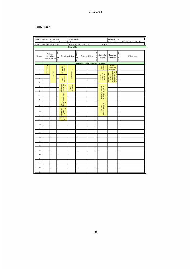
The Performa identified in Appendix A has been designed to aid in the development

of these plans. These guidelines should read in conjunction with the Performa

developed around the following minimum identified elements:

i) Summary Sheet – General information on the contingency plan.

ii) Decision Flow Chart – This should identify the process by which a

contingency plan is selected for use depending on the failure scenario

iii) Action Plan – Step by step summary of actions to be taken to resolve issues

and reinstate supply

iv) Procedures – Specific details of activities identified in the action plan

7/23/2019 Code Water Distribution Version 03

http://slidepdf.com/reader/full/code-water-distribution-version-03 53/62

  Version 3.0

52 

iv)  Plan Specific Information – Essential information for those managing the

event, for example consumers affected, volumes not supplied, location and

availability of materials

vi) Pumping Station and Valve Arrangements – Details and timings of

operations to be performed

vii) Contact Details – details for all personnel who should be contacted whilstimplementing the contingency plan

vii)  Time Line – A program of work to be undertaken and the expected duration

until reinstatement

ix) Network Schematic – Location plan of area with relevant valves, pumping

stations and pipelines identified.

x) In addition to this list, the date the plan was originally produced, the date it was

revised, the version number and the scenario description and location (where

appropriate) should be included.

Subject to procedures agreed between the DISCO  and Users  to ensure proper

confidentiality, copies of the emergency plans and manual of emergency operating

 procedures shall be maintained by the DISCO at a location to be notified to Users.

The plans and procedures shall be available for reference by Users at all reasonable

times.

In circumstances where Demand  cannot be met, the  DISCO shall supply water

intermittently in accordance with a Customer Water Rationing schedule issued by

the Water Control Centre and approved by the Bureau drawn up for the purpose of

securing Demand Control. Demand Control can include any of the following:

i)  Demand reduction initiated by Users;

ii)  Implementation of rota cuts by the DISCO;

iii)  Demand reduction instructed by the DISCO;

iv)  Reduced Customer  consumption initiated by water conservation and

 pricing incentives; and

v)  Other Water Demand Management policies.

8.  START-UP AND SHUT-DOWN PROCEDURES

8.1 Introduction

This section makes provision for procedures relating to

i)  The Start-up and Shut-down of Potable Water Plant or valve operations

which may cause Pressure Transients within the DISCO system or those

of Users; and

ii)  Recharging pipe work or other installations following internal access by

 personnel.

7/23/2019 Code Water Distribution Version 03

http://slidepdf.com/reader/full/code-water-distribution-version-03 54/62

7/23/2019 Code Water Distribution Version 03

http://slidepdf.com/reader/full/code-water-distribution-version-03 55/62

  Version 3.0

54 

The DISCO shall advise the User of the numbering and nomenclature to be used at

least one month prior to the proposed date of installation of such plant and equipment.

 Notification will be made in writing and will consist of both an Operation Diagram 

showing the plant to be installed, the proposed numbering and nomenclature and the

 proposed date of installation.

The Responsible Manager shall, on receipt of the notification, confirm that no other

Potable Water Plant  at the site has numbering and nomenclature which could be

confused with that proposed by the DISCO.

User plant on the DISCO site shall have numbering and nomenclature in accordance

with the system used by the DISCO. 

When either the DISCO or a User installs Potable Water Plant which is the subject

of this section of the WDOC, either the DISCO  or the User  respectively shall be

responsible for the provision of clear and unambiguous labelling showing the

numbering and nomenclature.

Where the DISCO changes the system of numbering and nomenclature of its plant,

the provisions of this section shall apply.

7/23/2019 Code Water Distribution Version 03

http://slidepdf.com/reader/full/code-water-distribution-version-03 56/62

  Version 3.0

55 

APPENDIX A - TYPICAL CONTINGENCY PLAN

Covering Sheet


CONTINGENCY PLAN SUMMARY INFORMATION

Scenario Equipment Failure - Pipeline

Geographic Locat ion Al Grayyeh

Reference AADC/Pipe failure/AL Grayeeh

Control Authority of Plan AADC

Locat ion of Master Document With HoD AADC

Copies held by

Version

Version

Name Location

Date Produced Originator Checker Approver  

Date revised Revisor Checker Approver  

This contingency plan should be reviewed as and when network or supply alterations impact on the

application of this plan. As a MINIMUM, this contingency plan should be updated once every twelve months


7/23/2019 Code Water Distribution Version 03

http://slidepdf.com/reader/full/code-water-distribution-version-03 57/62

  Version 3.0

56 

Decision Flow Chart


Date produced: Date Revised: Version:  A

Scenario: Equipment Failure - Pipeline Reference: AADC/Pipe failure/AL Grayeeh

Supply location:  Al Grayyeh Control authority for plan:  AADC

EQUIPMENT FAILURE - DISCO CONTINGENCY PLAN

Direct Consumers Consumers

Distribution

TRANSCO responsibility DISCO responsibility

FLOW CHART

Yes

No

Note 1: Insert relevant reference number here.

02/12/2003

Storage 2Storage 1

Distribution failure reported to DISCO

customer complaints centre or directly

to HoD of affected area by DISCO

operatives or by Consumer 

HoD for area assesses need for

contingency plan depending on cause

and severity of failure

1 2

Pump Station Failure Pipeline Failure

DISCO to instigate Contingency Plan y1, in

conjunction with WCC Contingency PlanY

1

- Assess level of storage

- Inform WCC if reduced supply required

- Expedite supply to affected consumers

- Operate alternative valving schedule

- Instigate repair schedule

DISCO to instigate Contingency Plan

x

1

, in conjunction with WCCContingency Plan X

1

- Assess level of storage

- Inform WCC if reduced supply required

- Expedite supply to affected consumers

- Operate alternative valving schedule

- Instigate repair schedule

DISCO confirmation of problem

received?

DISCO operators assess cause of

failure

DISCO operators report cause

of failure to HoD for area.


7/23/2019 Code Water Distribution Version 03

http://slidepdf.com/reader/full/code-water-distribution-version-03 58/62

  Version 3.0

57 

Action Plan


Date produced: Date Revised: Version:  A

Scenario: Equipment Failure - Pipeline Reference: AADC/Pipe failure/AL Grayeeh

Supply location:  Al Grayyeh Control authority for plan:  AADC

 ACTION PLAN

Size of Main and Main diameter:

Repair Time Expected repair time (see time line chart attached)

Item Action Required

02/12/2003

10-12 hours

600mm

 Action Plan

(Carry out

actions in

conjunction with

planning chart,

network

schematic and

additional

information

contained in this

plan)

HoD for area to advise

contingency plan in operation and

provide information on progress of

repair and reinstatement

Inform DISCO

Tankering unit

Inform O&M

contingency plan

operational

Inform Customer Services

of problem and expected

progress

Inform O&M

repair teams

 Arrange supplies

to Critical/VIP

consumers

 Arrange supplies to

other consumers

Normal

supply

resumed?

Continue

tankering

Stop tankering

Isolate failure

Reinstate normal supply

Normal

supply

resumed?

Continue

alternative

supply

Customer services

inform consumers

normal supply resumed

Normal supply

resumed?

Customer services to

provide information to

consumers when

contacted

Inform TRANSCO  of

impact on supply and to

shutdown of Military PS

Carry out repair 

Update HoD of area of

any change in schedule

Normal

supply

resumed?

 Assess storage and

likely duration of event

Implement alternative

supplies if available

If event >6 hours repair

incident report for RSB and

submit within 48 hours of

event

No

Yes

No

No

No

Yes

Yes

Yes


7/23/2019 Code Water Distribution Version 03

http://slidepdf.com/reader/full/code-water-distribution-version-03 59/62

  Version 3.0

58 

Procedures

 Date produced: Date Revised: Version:  A

Scenario: Equipment Failure - Pipeline Reference: AADC/Pipe failure/AL Grayeeh

Supply location:  Al Grayyeh Control authority for plan:  AADC

PROCEDURES

Date produced: Date Revised: Version:  A

Scenario: Equipment Failure - Pipeline Reference: AADC/Pipe failure/AL Grayeeh

Supply location:  Al Grayyeh Control authority for plan:  AADC

PLAN SPECIFIC INFORMATION

Customers in the following locations could be affected:

Demand Other information

 Al Grayyeh South 0.46 MGD Agricultural

Demand Hours

0.46 MGD 5 hours/d

0.5 5 hours/d

Shut off plan checked: Yes / No Yes

Valves checked: Date:

By Whom:

Status: HoD area

Fittings required (for guidance) 600mm Pipeline

Couplings to fit 630 - 647mm

Repair clamps to fit 625 - 645 mm

repair clamp to fit ranges 584 - 680

 Availability  All available

Location of parts  AW02

Contacts

02/12/2003

 Available Storage

 Assessment

 Assess whether customer storage will cover duration of event by estimating duration between last supply to area and

the average consumption to assess remaining hours storage.

VIP consumers

supply

 Arrangements

Tankered supply required immediately for critical customers without storage. Secondary supplies must also be in

place for sensitive customers, before storage is no longer available.

Other consumer

supply

arrangements

If event will rely on >24 hours usage of customer storage, tankered supplies should be arranged as above, once all

critical and sensitive customers are supplied.

Valve schedule Operate valves as shown on valving schedule and network schematic.

Water Quality Follow AADC standard flushing, disinfection and recommisioning procedure.

HSE Procedure Follow AADC standard HSE procedures.

Contamination N/A

Repair procedure See time line.

Customer

Notification

If event will impact on customers, inform customer complaints of reason for failure and expected time for repair. Keep

customers complaints up to date with progress.

02/12/2003

 Affected

Customers Reference Location Supply Hours supply

Timed 5 hrs/day

Type Customer Location Supply

Large Customers  Al Grayyeh South Timed

Sensitive Customers  Agrilcultural Timed

Vulnerable

Customers

Comment:

Secondary

Supply

Requirements

During a contingency event the

following domestic and essential

use demand may need to be met

through tankered supplies.

Location

Supply required during

event MGD

Nr 3000 gallon tanker trips

required

 Al Grayyeh South 0.23 77

Valving

operations

Materials /

Fittings

 Availability

Water Quality Under normal conditions, it is reasonable to resume supply after an acceptable result from a physical test of the

following parameters whilst waiting for laboratory water quality results.

Parameter Value Parameter Value

Residual Chlorine Colour  

Turbidity pH

Name Position Number  

 Additional

Information

Comment:

0.6 MGD & 0.3 MGD storage

available

In any other situation the standard water quality regulations must be followed.

Solids


7/23/2019 Code Water Distribution Version 03

http://slidepdf.com/reader/full/code-water-distribution-version-03 60/62

  Version 3.0

59 

Critical Valve Arrangement


Date produced: Date Revised: Version:  A

Scenario: Equipment Failure - Pipeline Reference: AADC/Pipe failure/AL Grayeeh

Supply location:  Al Grayyeh Control authority for plan:  AADC

CRITICAL VALVE ARRANGEMENT

Valves

Select

02/12/2003

List the critical valves within the network considered in this contingency plan and shown on Network Schematic. Onimplementation of contingency plan identify which valves will require operation to isolate failure and for any rezoning

operations.

Valve reference Location Operation Information

V1/V2 Close

V5/V6 Close


7/23/2019 Code Water Distribution Version 03

http://slidepdf.com/reader/full/code-water-distribution-version-03 61/62

  Version 3.0

60 

Time Line


Date produced: Date Revised: Version:  A

Scenario: Equipment Failure - Pipeline Reference:  AADC/Pipe failure/AL Grayeeh

Supply location:  Al Grayyeh Control authority for plan:  AADC

TIME LINE

Time in hours after notification of burst

1

I  ni   t  i   a t   e

 pl   an

Inform

complaints

department

2

3

4

5

6

7

8

9

W a t   er 

 Q u al  i   t   y 

T  e s  t  

10

11

12

Pressure

Test

13

14

15

16

17

18

19

20

21

22

23

24

02/12/2003

Hours

Valving

operations

and rezoning

A  c  t   u al  T i  m e

Repair activities

 C l   o s  e of  f  m ai  n

R ez  oni  n g

M o b i  l  i   s  e

r  e p ai  r  t   e am

 C  ol  l   e c  t  f  i   t   t  i  n g s 

E x  c  av  a t   e

 pi   p e

Customer

Relations

A  c  t   u al  T i  m e

Milestones

T  ank  er  s  t   o

v  ul  n er  a b l   e

 c  u s  t   om er  s 

I  nf   or m c  u s  t   om er  s 

 of   pr  o b l   em an d 

 t   ank  er i  n g /   al   t   er n a t  i  

v  e s  u p pl   y 

 ar r  an g em en t   s 

A  c  t   u al  T i  m e

E x  c  av  a t   e

 an d  c  u t   o u t  

 b r  ok  en pi   p e

F i   t   t  i  n g s  t   o

 s i   t   e

T  ank  er  s  t   ol   ar  g e an d 

 s  en s i   t  i  v  e c  u s  t   om er  s 

Other activities

A  c  t   u al  T i  m e

Secondary

supplies

M ak  er  e p ai  r 

T  ank  er  s  t   o al  l   o t  h  er 

 c  u s  t   om er  s 

R e c h  ar  g e

 an d 

r  e c  ommi   s i   on


7/23/2019 Code Water Distribution Version 03

http://slidepdf.com/reader/full/code-water-distribution-version-03 62/62

  Version 3.0

Network Schematic


Date produced: Date Revised: Version:  AScenario: Equipment Failure - Pipeline Reference:  AADC/Pipe failure/AL GrayeehSupply location:  Al Grayyeh Control authority for plan:  AADC

NETWORK SCHEMATIC

 Awaiting schematic

02/12/2003

F  ai    l     ur   e

V 1  

V 2  

V  3  V 

4  

V  6  

V  5  

F  ai    l     ur   e


Recommended