COMPLEX/UC/P/D2.1.2/1.0 Public
SystemC Generation tools from MARTE and Stateflow
Page i
Public
FP7-ICT-2009- 4 (247999) COMPLEX
COdesign and power Management in
PLatform-based design space EXploration
Project Duration 2009-12-01 – 2012-11-30 Type IP
WP no. Deliverable no. Lead participant
WP2 D2.1.2 UC
SystemC Generation tools from MARTE and
Stateflow
Prepared by F. Herrera, P. Peñil, E. Villar (UC)
F. Ferrero, Raul Valencia (GMV)
L. Lavagno (PoliTo), D. Quaglia (EdaLab)
Issued by UC
Document Number/Rev. COMPLEX/UC/P/D2.1.2/1.0
Classification COMPLEX Public
Submission Date 2011-06-16
Due Date 2011-05-30
Project co-funded by the European Commission within the Seventh Framework Programme (2007-2013)
© Copyright 2010 OFFIS e.V., STMicroelectronics srl., STMicroelectronics Beijing R&D Inc, Thales
Communications SA, GMV Aerospace and Defence SA, CoWare NV, ChipVision Design Systems AG,
EDALab srl, Magillem Design Services SAS, Politecnico di Milano, Universidad de Cantabria, Politecnico di
Torino, Interuniversitair Micro-Electronica Centrum vzw, European Electronic Chips & Systems design
Initiative.
This document may be copied freely for use in the public domain. Sections of it may be copied provided
that acknowledgement is given of this original work. No responsibility is assumed by COMPLEX or its
members for any aplication or design, nor for any infringements of patents or rights of others which may result
from the use of this document.
COMPLEX/UC/P/D2.1.2/1.0 Public
SystemC Generation tools from MARTE and Stateflow
Page 2
History of Changes
ED. REV. DATE PAGES REASON FOR CHANGES
UC 1.0 2011-06-16 67 First version
COMPLEX/UC/P/D2.1.2/1.0 Public
SystemC Generation tools from MARTE and Stateflow
Page 3
Contents
1 Introduction ........................................................................................................................ 4
1.1 Scope ........................................................................................................................... 4
1.2 Acronym list ................................................................................................................ 4
1.3 Glossary ....................................................................................................................... 5
2 Tool Support for Generation of a high-level executable model of the system in SystemC 7
3 Generation from the MARTE model ................................................................................. 8
3.1 General Description ..................................................................................................... 8
3.2 Model Analyzer ......................................................................................................... 10
3.3 CFAM generator ........................................................................................................ 17
3.4 XML generator .......................................................................................................... 27
3.5 Stimuli generator ....................................................................................................... 31
3.6 IP/XACT generator .................................................................................................... 33
3.7 Design Space Exploration plug-in ............................................................................. 36
4 Generation of Executable Models from Stateflow ........................................................... 38
4.1 Generation of SystemC .............................................................................................. 40
4.2 Generation of (C/C++) .............................................................................................. 40
5 Non-Functional Constraints in the COMPLEX flow ....................................................... 42
5.1 Capturing of non-functional Constraints in the MARTE model ............................... 42
5.2 Using of Non-Functional Constraints in the MARTE-related COMPLEX flow ...... 45
6 Acronym List .................................................................................................................... 48
7 References ........................................................................................................................ 49
Annex 1: COMPLEX Eclipse Application User Manual ......................................................... 52
1. Introduction ................................................................................................................... 52
2. Installation ..................................................................................................................... 52
3. Usage ............................................................................................................................. 54
3.1. COMPLEX menu in the menu bar ............................................................................ 55
3.1.1. COMPLEX→Analyze model ................................................................................ 58
3.1.2. COMPLEX→Generate→CFAM code skeletons .................................................. 58
3.1.3. COMPLEX→Generate→Application executable model→System C executable 58
3.1.4. COMPLEX→Generate→Application executable model→Performance analysis
executable ............................................................................................................................. 59
3.1.5. COMPLEX→Generate→XML System Description file ...................................... 59
3.1.6. COMPLEX→Generate→Stimuli environment ..................................................... 59
3.1.7. COMPLEX→Generate→XML Design Space file and Exploration script ........... 59
3.1.8. COMPLEX→ Generate→IPXACT specification ................................................. 59
3.1.9. COMPLEX→Start DSE ........................................................................................ 60
3.1.10. COMPLEX→Configure ..................................................................................... 60
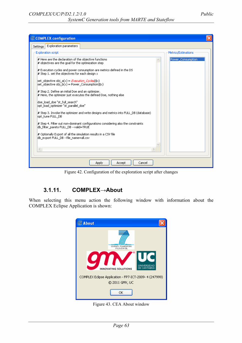
3.1.11. COMPLEX→About ........................................................................................... 63
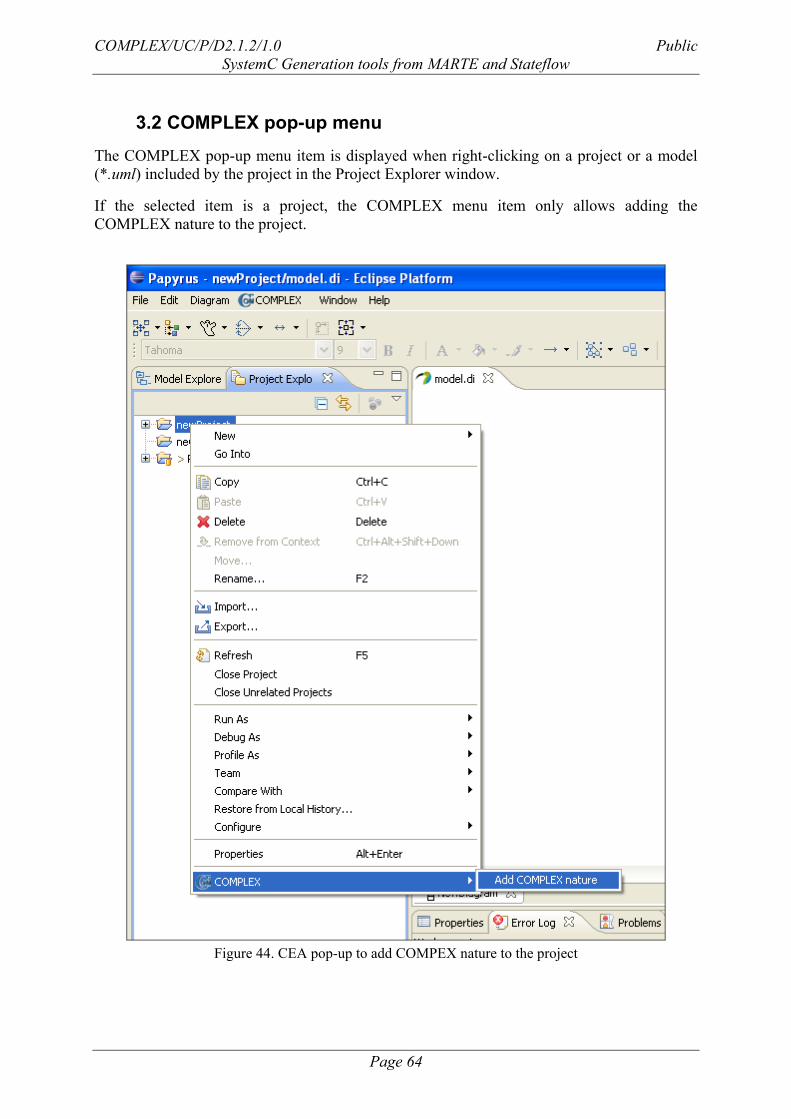
3.2 COMPLEX pop-up menu ............................................................................................... 64
COMPLEX/UC/P/D2.1.2/1.0 Public
SystemC Generation tools from MARTE and Stateflow
Page 4
1 Introduction
1.1 Scope
This document corresponds to the output deliverable of the task 2.1 “Model-driven design
front-end” for the work package 2 within the COMPLEX project (see the Description of
Work, DoW [1]). It depends of the deliverable D1.2.1 “Definition of application, stimuli and
platform specification, and definition of tool interfaces” (see [2]) in terms of goals and
requirements for the design front-end, as well as the requirements on the interfaces with other
tasks of the COMPLEX design flow.
Task 2.1 aims to define a system-level specification methodology by means of two different
modelling languages, UML/MARTE and Stateflow, identifying all those features of the
system-level modelling language relevant for the characterization of the system functional and
non-functional properties and the estimation of system performance.
In order to develop an executable model of the system, it is necessary to transform the high-
level models into an executable, SystemC specification, which enables fast functional
validation, and performance estimations. This way, such SystemC specification will make
feasible in the COMPLEX design flow, the optimization of the system architecture after a
design space exploration (DSE) phase with a reasonable bound in time. This document
addresses this transformation and provides a first insight on the implementation of the tools
required for carrying out the task.
This is a public document that describes the system-level specification and the transformation
from the system-level model to the SystemC and IP-XACT models. This document is not
intended for evolving along the COMPLEX project, but must serve as a basis for the
development of the transformation tools in task 2.2 (see DoW, [1]).
1.2 Acronym list
The following table lists all the acronyms used along this document:
Table 1: Acronym list
Acronym Definition
AEM Application Executable Model
API Application Programming Interface
CEA COMPLEX Eclipse Application
CFAM Concurrent Functional Application Model
CMC COMPLEX Model Checker
CPU Central Processing Unit
DoW Description of Work
DRM Detailed Resource Modelling
DSE Design Space Exploration
COMPLEX/UC/P/D2.1.2/1.0 Public
SystemC Generation tools from MARTE and Stateflow
Page 5
Acronym Definition
GCM Generic Component Model
GQAM Generic Quantitative Analysis Modelling
GRM Generic Resource Modelling
HLAM High-Level Application Modelling
M2T Model to Text
MARTE Modelling and Analysis for Real-time and Embedded Systems
MDA Model Driven Architecture
MDD Model Driven Development
MOF MetaObject Facility
MOST Multi-Objective System Tune
MTL Model to Text Langue
MTL Model to Text Language
NFP Non-Functional Properties
PAM Performance Analysis Modelling
PDM Platform Description Model
PIM Platform Independent Model
PSM Platform Specific Model
QoS Quality of Service
RTES Real-Time and Embedded Systems
SAM Schedulability Analysis Modelling
SW Software
TBC To Be Completed
TBD To Be Defined
UML Unified Modelling Language
1.3 Glossary
The following table summarizes the most important concepts provided along this document:
Table 2: Definition list
Definition Description
CFAM Concurrent Functional Application Model
CFAM API API for accessing real-time and communication and
synchronization services from CFAM code
CFAM code Sources (User code) of the CFAM
CFAM Component
Structure
Sources reflecting the Component-based structure of the
application and generated from the UML/MARTE model.
COMPLEX/UC/P/D2.1.2/1.0 Public
SystemC Generation tools from MARTE and Stateflow
Page 6
CFAM Generator Code Generation Engine which extracts from the COMPLEX
UML/MARTE specification the Component Structure and
other information (concurrency structure, etc) and generate the
code which reflects (by means of a set of macros and facilities
common to different implementation possibilities).
CFAM Infrastructure Set of implementations available for the CFAM Component
Structures produced by the CFAM Generator, and grouped for
each Simulation and Analysis Infrastructure supported.
Platform Independence Platform independence is a quality, which a model may
exhibit. This is the quality that the model is independent of the
features of a platform of any particular type (see [8]).
Platform Model A set of technical concepts, representing the different kinds of
parts that make up a platform and the services provided by the
platform.
Platform-Independent
Model (PIM)
The MDA model that defines an application independent of a
specific platform. The PIM is applied to a more detailed
model using a transformation mechanism (see [8]).
Platform-Specific
Model (PSM)
The MDA model that refers to or includes elements from the
implementation platform, often made more precise through
the use of relevant stereotypes (see [8]).
Specification The set of information which serves as an input for an
implementation flow. It may include a model or a set of
models, functional and non-functional constraints.
Transformation A model operation that takes one or more models as input and
returns one or more models as output. The operation maps
elements from the source model elements to the target model
elements.
Transformation Chain If a sequence of more than one transformation is applied to an
input model, the configuration of these transformations –
including their sequence, possible branches and other
information – is called transformation chain.
View A viewpoint model or view of a system is a representation of
that system from the perspective of a chosen viewpoint.
Viewpoint A viewpoint on a system is a technique for abstraction using a
selected set of architectural concepts and structuring rules, in
order to focus on particular concerns within that system. Here
„abstraction‟ is used to mean the process of suppressing
selected detail to establish a simplified model.
The concepts and rules may be considered to form a
viewpoint language.
COMPLEX/UC/P/D2.1.2/1.0 Public
SystemC Generation tools from MARTE and Stateflow
Page 7
2 Tool Support for Generation of a high-level executable model of the system in SystemC
The COMPLEX system-level specification methodology aims to define methods, tools and
techniques to support the modelling of real-time embedded systems, paying special attention
to those system aspects related to performance and power estimation.
Two different, but complementary design entries corresponding to two different MDA (see
[8]) design entries described in the DoW [1], where defined in [3].
While in [3], the specification methodologies where introduced and presented, a set of
generation engines were introduced. These generation engines transform the system
description of the system in standard text-based formats, which can be understood and
processed by the front-ends of the tools and frameworks in charge of producing the
executable model suitable for functional verification, performance analysis and design space
exploration.
Specifically, this documents reports the generators from the UML/MARTE specification in
section 3. Then, in section 3.7, the generators from the Stateflow description are reported.
Finally, in section 5, the capture of non-functional constraints is introduced. This extends [3]
in order to give a full vision of the MARTE/UML specification methodology. Further
refinements of the methodology (achieved after the development and refinement of the
generators, and in general, of the COMPLEX framework) are being reported in later updates
of [3].
COMPLEX/UC/P/D2.1.2/1.0 Public
SystemC Generation tools from MARTE and Stateflow
Page 8
3 Generation from the MARTE model
3.1 General Description
The COMPLEX Eclipse Application (CEA) is the direct result of task 2.1. This application
has been developed over the Eclipse Helios framework, mainly using open standards for the
implementation of the transformation engines. It is aimed to help a modelling environment
that allows the user to:
Model the system at both application and platform levels.
Generate the CFAM and SystemC executable models.
Generate the IPXACT specification from the system platform.
And finally, execute the Design Space Exploration loop.
This application integrates an infrastructure consisting in the following elements:
UML Profiles: MARTE and COMPLEX specific profiles.
A set of analysis tools that guides the user during the system modelling.
A set of transformation tools, to obtain from the UML/MARTE model text-based
representations suitable for the production of the SystemC executables for validation,
performance estimation and DSE exploration
A set of options for triggering DSE activities.
The CEA tool has been made available in the COMPLEX Eclipse update site:
http://offis.complex.de/eclipseupd/release/
which, in turn, is placed in the COMPLEX website.
The following image depicts the Eclipse interface including the CEA tool interface. The
graphical user interface is mainly based on user menus, pop-up menus over UML models and
messages windows that interact with the user during the different operations.
COMPLEX/UC/P/D2.1.2/1.0 Public
SystemC Generation tools from MARTE and Stateflow
Page 9
Figure 1. COMPLEX menu is available after the installation of the COMPLEX menu. OLD FIGURE
As it is shown in Figure 1, the COMPLEX menu enables several options:
To analyze the model
To trigger any of the different generators
To trigger the Design Exploration tool
To configure the COMPLEX framework
To give information about the authoring
Following subsections will focus on the two former features of the COMPLEX Eclipse
Application.
The model analyzer is in charge of guaranteeing the COMPLEX nature of the project and it is
able to check that the model includes all the COMPLEX required views.
The generators enable the user to independently trigger each of the different code generators
from the UML/MARTE model. Namely, the user can independently generate the following
code:
1. CFAM skeletons
2. XML System Description (including also additional information for performance
analysis)
3. XML Design Space (DS) description and DS Exploration rules
4. SystemC description of the Environment producing the Input Stimuli
5. IP/XACT description of the HW Platform of the System
Additionally, there are menu options for producing:
COMPLEX/UC/P/D2.1.2/1.0 Public
SystemC Generation tools from MARTE and Stateflow
Page 10
A platform independent model (PIM) in SystemC
The platform dependent model (PDM), which requires the trigger of previous
generators (except for the IP/XACT one).
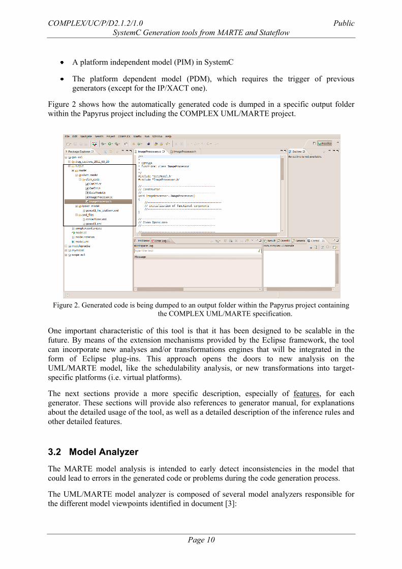
Figure 2 shows how the automatically generated code is dumped in a specific output folder
within the Papyrus project including the COMPLEX UML/MARTE project.
Figure 2. Generated code is being dumped to an output folder within the Papyrus project containing
the COMPLEX UML/MARTE specification.
One important characteristic of this tool is that it has been designed to be scalable in the
future. By means of the extension mechanisms provided by the Eclipse framework, the tool
can incorporate new analyses and/or transformations engines that will be integrated in the
form of Eclipse plug-ins. This approach opens the doors to new analysis on the
UML/MARTE model, like the schedulability analysis, or new transformations into target-
specific platforms (i.e. virtual platforms).
The next sections provide a more specific description, especially of features, for each
generator. These sections will provide also references to generator manual, for explanations
about the detailed usage of the tool, as well as a detailed description of the inference rules and
other detailed features.
3.2 Model Analyzer
The MARTE model analysis is intended to early detect inconsistencies in the model that
could lead to errors in the generated code or problems during the code generation process.
The UML/MARTE model analyzer is composed of several model analyzers responsible for
the different model viewpoints identified in document [3]:
COMPLEX/UC/P/D2.1.2/1.0 Public
SystemC Generation tools from MARTE and Stateflow
Page 11
Platform Independent Model (PIM) analysis: responsible for the analysis of the Data,
Functional, Communications & Concurrency views (that compose the MARTE PIM).
It also performs additional checks on the Architectural view (although it is associated
to the PSM.) These checks on the Architectural view are necessary when analyzing the
PIM as the CFAM generator uses the DSE constraints that appear in that view to
derive the XML System Properties file..
Platform Description Model (PDM) analysis: responsible for the analysis of the
Platform view.
Platform Description Model (PSM) analysis: responsible for the analysis of the
Architectural view.
Finally, the analysis of the Verification view, which analyzes how the external sub-
systems interact with the system.
In general, the checks to carry out are directly related with the constraints specified in the
COMPLEX design methodology. When an issue is detected in the model, it will be notified to
the user using the Eclipse framework facilities.
The issues arisen during the model analysis are classified into two different kinds of severity:
“Error”: in case that the problem in the model would lead to errors in the generation
process.
“Warning”: In case that the problem in the model could generate errors in the
generated code (that would raise during the simulation).
The following image shows the Eclipse error log view with the result of an analysis on the
UML/MARTE model:
Figure 3. Eclipse error log after the analysis
The Error log provides detailed information to the user about the cause of the problem.
Moreover, it indicates in what model view the issue arose.
If the analysis reported errors, the Eclipse problems view shows a message indicating the type
of problem, the UML model where the error was detected and the path to the UML file. In
case an error is included in this Eclipse view, no code and/or text generation will be
performed by the transformation engines until it is removed. The following image depicts the
problem view in case of errors.
COMPLEX/UC/P/D2.1.2/1.0 Public
SystemC Generation tools from MARTE and Stateflow
Page 12
Figure 4. Eclipse problems view after the analysis
The following sections detail the checks carried out over each of the model viewpoints
defined in document [3], including the specific view on which they are carried out, a short
description of their purpose and their specific severity.
It must be taken into account that the checks shown in the following sections represent a very
first version of the MARTE model analyzer, that will be improved in the future based on the
results of applying the COMPLEX methodology on the Use Case 3.
3.2.1 PIM analysis
The next table show the checks carried out by the PIM analyzer. These checks are the
necessary previous step to the generation of the CFAM model from the PIM.
Table 3 : List of checks carried out by the PIM analyzer
ID View Description Severity
1 Data All data types should include a private
variable of type NFP_DataSize
Warning
2 Functional All data types shall only include one private
variable of type NFP_DataSize
Error
3 Data This view must not declare any other UML
element different than:
Signal, DataType, Enumeration
Warning
4 Functional This view must declare only the following
UML elements:
Class, Interface, Use Case, Actor,
Association, InterfaceRealization,
Dependency
Warning
COMPLEX/UC/P/D2.1.2/1.0 Public
SystemC Generation tools from MARTE and Stateflow
Page 13
5 Functional An interface stereotyped with
ClientServerSpecification should be
referenced by at least one interface
realization and one dependency association
(i.e., the interface should be implemented by
at least one class and used at least by another
one)
Warning
6 Functional All operations in interfaces stereotyped with
ClientServerSpecification should be public
Warning
7 Communications
& Concurrency
This view must declare only the following
UML elements:
Components (and their corresponding
internal elements), Interactions (and their
corresponding internal elements, for
sequence diagrams)
Warning
8 Communications
& Concurrency
Only ports, properties and connectors should
compose the components in the this view
Warning
9 Communications
& Concurrency
The parts of the components in this view
shall be instances of the functional classes
defined in the Functional view
Error
10 Communications
& Concurrency
ClientServerPorts shall not be typed Error
11 Communications
& Concurrency
An RtContext shall not be null Error
12 Communications
& Concurrency
The class type of the component‟s part
which owns a port connected to a
ClientServerPort shall realize the same
interface that specified in the
ClientServerPort stereotype whenever it is
provided
Error
13 Communications
& Concurrency
All provided ClientServerPorts shall be
stereotyped with an RtFeature, which shall
have at least one associated RtSpecification
Error
14 Communications
& Concurrency
The user should not expose both cyclical and
sporadic provided operations through the
same ClientServerPort
Warning
15 Communications
& Concurrency
Component internal parts‟ ports shall be
typed with an interface (from those that
appear in the Functional view) in case they
are not directly connected to a component‟s
ClientServerPort
Error
COMPLEX/UC/P/D2.1.2/1.0 Public
SystemC Generation tools from MARTE and Stateflow
Page 14
16 Communications
& Concurrency
RtSpecifications shall be always associated
to ClientServerPorts (also stereotyped with
RtFeature)
Error
17 Communications
& Concurrency
Component internal parts‟ ports shall not be
stereotyped with ClientServerPort
Error
18 Communications
& Concurrency
Component‟s external ports shall be typed
with an interface in case they are not
stereotyped with ClientServerPorts (note
that these kind of ports are always
considered as required)
Error
19 Communications
& Concurrency
Component‟s external ports should be typed
with an interface from those that appear in
the Functional view in case they are not
stereotyped with ClientServerPorts (note
that these kind of ports are always
considered as required)
Warning
20 Architectural A DSE constraint must only be attached to a
HWComputingResource
Error
21 Architectural An application component port shall not be
connected to more than one application
component
Error
22 Functional All operations in interfaces stereotyped with
ClientServerSpecification must have up to
one parameter, and no more
Error
23 Communications
& Concurrency
A RtSpecification shall have at least valid
values for the occKind and absDl attributes
Error
24 Data, Functional
and
Communications
& Concurrency
All VSL expressions in the model shall
conform the VSL standard
Error
The PIM analyzer is implemented on the COMPLEX MARTE2CFAM plug-in (see section
3.3) integrated in the COMPLEX Eclipse Application (CEA).
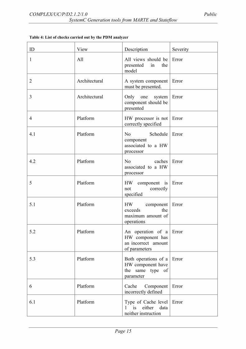
3.2.2 PDM analysis
The PDM analyzer writes the errors detected in the file PlatformErrorsFile. By using an error
message window, designer is warned about the errors in the model. The next table shows the
checks carried out by the PDM analyzer:
COMPLEX/UC/P/D2.1.2/1.0 Public
SystemC Generation tools from MARTE and Stateflow
Page 15
Table 4: List of checks carried out by the PDM analyzer
ID View Description Severity
1 All All views should be
presented in the
model
Error
2 Architectural A system component
must be presented.
Error
3 Architectural Only one system
component should be
presented
Error
4 Platform HW processor is not
correctly specified
Error
4.1 Platform No Schedule
component
associated to a HW
processor
Error
4.2 Platform No caches
associated to a HW
processor
Error
5 Platform HW component is
not correctly
specified
Error
5.1 Platform HW component
exceeds the
maximum amount of
operations
Error
5.2 Platform An operation of a
HW component has
an incorrect amount
of parameters
Error
5.3 Platform Both operations of a
HW component have
the same type of
parameter
Error
6 Platform Cache Component
incorrectly defined
Error
6.1 Platform Type of Cache level
1 is either data
neither instruction
Error
COMPLEX/UC/P/D2.1.2/1.0 Public
SystemC Generation tools from MARTE and Stateflow
Page 16
6.2 Platform Type of a Cache
level greater than one
is not unified
Error
3.2.3 PSM analysis
The PSM analyzer writes the errors detected in a file, specifically, the DSEErrorsFile. By
using an error message window, designer is warned about the errors in the model. The next
table shows the checks carried out by the PSM analyzer:
Table 5 List of checks carried out by the PSM analyzer
ID View Description Severity
1 All All views should be
presented in the
model
Error
2 Platform and
Architectural
A DSE parameter
incorrectly specified
Error
3 Architectural A DSE rule with not
reference to DSE
parameters
Error
4 Architectural A DSE rule
incorrectly specified
Error
3.2.4 Verification view analysis
The verification view analyzer writes the errors detected in a file, specifically, the
VerficationErrorsFile. By using an error message window, designer is warned about the errors
in the model. The next table shows the checks carried out by the verification analyzer:
Table 6 List of checks carried out by the verification analyzer
ID View Description Severity
1 Functional No external
interfaces in the
model
Error
2 Verification No scenarios in the
model
Error
3 Verification No
GaResourcesPlatform
element in the model
Error
4 Verification More than one
GaResourcesPlatform
Error
COMPLEX/UC/P/D2.1.2/1.0 Public
SystemC Generation tools from MARTE and Stateflow
Page 17
element in the model
5 Verification No External
subsystems in the
environment
Error
6 Verification No system element in
the environment
Error
7 Verification More than one
system element in the
environment
Error
8 Functional Incorrect
specification of the
external interface
operations
Error
8.1 Functional An external interface
has no services
Error
8.2 Functional An operation of an
external interface is
not a RtService.
Error
8.3 Functional A RtService is not
synchronous
Error
3.3 CFAM generator
The CFAM generator is implemented by the COMPLEX MARTE2CFAM plug-in integrated
in the COMPLEX Eclipse Application.
It consists of an Eclipse plug-in that transforms the UML/MARTE model into the CFAM
skeletons and a set of functional code containers (written in C++) that abstracts the functional
code from the execution platform. This generated code will be the input for the SCoPE+ tool,
which is in charge of performing the high-level estimation of the system.
The COMPLEX MARTE2CFAM plug-in also produces the XML System Properties file from
the UML model which describes the non-functional properties defined in the model:
Application level non-functional properties for all system functions in terms of timing
constraints.
System level non-functional properties at the architectural system description in terms
of constraints on the execution of the DSE loop.
The main features of this transformation engine are summarized bellow:
Full integration in Eclipse framework by means of the extension mechanism described
in section 3.1.
COMPLEX/UC/P/D2.1.2/1.0 Public
SystemC Generation tools from MARTE and Stateflow
Page 18
The core transformation engine can be also distributed as a standalone plug-in to be
integrated with any Eclipse plug-in.
Analysis of the Platform Independent Model (PIM), including the Data, Functional
and Communications & Concurrency views.
Generation of the CFAM executable model supported by the CFAM simulation
architecture described in [4]:
o CFAM code skeletons for the user functional code (C++)
o CFAM data types and structures (ANSI C)
o CFAM containers (C++)
o Makefile to support the CFAM
Generation of the SystemC executable model, supported by the CFAM simulation
architecture described in [4]. This simulation infrastructure allows sharing the CFAM
code skeletons and containers between the CFAM and SystemC executable models
without modifying any line of, but only modifying the compilation rules in the
makefiles.
Implemented in MTL, thus easily portable to other transformation engines. It is
necessary that the host environment have installed ACCELEO [21]
Generation of header files necessary by the CFAM simulation infrastructure to
generate the CFAM executable model.
Generation of comments in the generated code tracing back to the requirements
included in the model.
The MARTE2CFAM generator produces the following outputs:
ANSI C data types and structures corresponding to the Data view of the
UML/MARTE model.
CFAM code, which corresponds to the C++ code skeletons that will be filled by the
user when implementing system functions. This code skeletons match to the classes
defined in the Functional view of the UML/MARTE model.
C++ classes corresponding to the CFAM components. These are the containers of the
previously auto-generated C++ code skeletons. They are used to abstract that code
from the specific execution platforms and the allocation of the different system
functionalities. The system components are those defined in the Communications &
Concurrency view of the UML/MARTE model.
Makefiles for the system simulation that includes the necessary information to
compile the model and generate the SCoPE+ and SystemC executable models. Though
the two models rely on the SystemC libraries, the first one provides system metrics
and estimations during the simulation. The following rules are provided in the
makefile:
o systemc: compiles the system for SystemC simulation.
COMPLEX/UC/P/D2.1.2/1.0 Public
SystemC Generation tools from MARTE and Stateflow
Page 19
o scope: compiles for high-level SCoPE+ simulation.
o run: executes the previously compiled solution for System C.
o run_scope: executes the previously compiled solution for SCoPE+ in order to
obtain system metrics and estimations.
The following figure shows an example of the outputs generated by the MARTE2CFAM
generator. These outputs are automatically generated into the Eclipse project directory and are
shown in the Eclipse project explorer:
Figure 5. Output of the CFAM generator
The following subparagraphs identify the different transformations done by the CFAM
transformation engine from the PIM views defined in the UML/MARTE model.
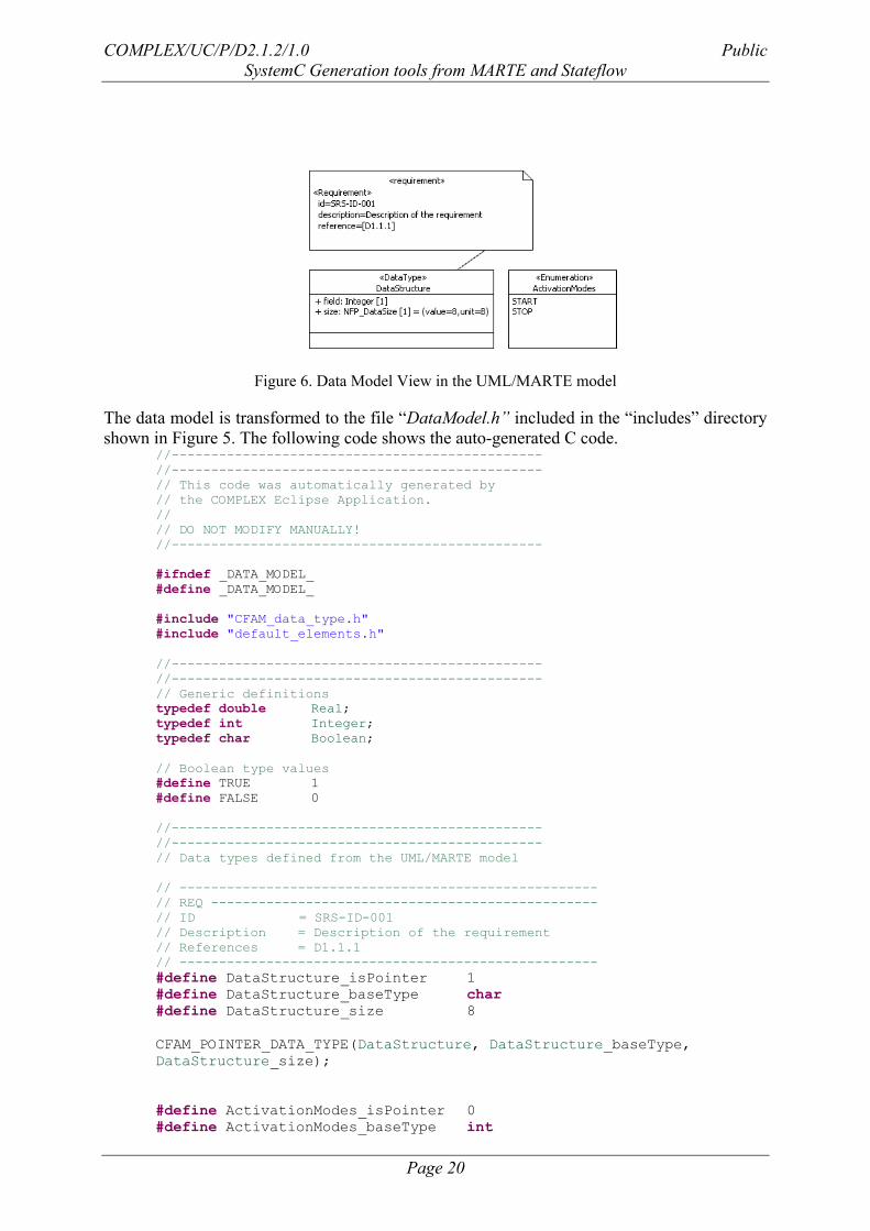
3.3.1 Data Model and CFAM code Skeletons
The first step consists of the generation of the data model. The following image depicts the
UML Data model for a Producer Consumer model, where the producer exchanges a simple
data structure with the consumer.
COMPLEX/UC/P/D2.1.2/1.0 Public
SystemC Generation tools from MARTE and Stateflow
Page 20
Figure 6. Data Model View in the UML/MARTE model
The data model is transformed to the file “DataModel.h” included in the “includes” directory
shown in Figure 5. The following code shows the auto-generated C code. //-----------------------------------------------
//-----------------------------------------------
// This code was automatically generated by
// the COMPLEX Eclipse Application.
//
// DO NOT MODIFY MANUALLY!
//-----------------------------------------------
#ifndef _DATA_MODEL_
#define _DATA_MODEL_
#include "CFAM_data_type.h"
#include "default_elements.h"
//-----------------------------------------------
//-----------------------------------------------
// Generic definitions
typedef double Real;
typedef int Integer;
typedef char Boolean;
// Boolean type values
#define TRUE 1
#define FALSE 0
//-----------------------------------------------
//-----------------------------------------------
// Data types defined from the UML/MARTE model
// -----------------------------------------------------
// REQ -------------------------------------------------
// ID = SRS-ID-001
// Description = Description of the requirement
// References = D1.1.1
// -----------------------------------------------------
#define DataStructure_isPointer 1
#define DataStructure_baseType char
#define DataStructure_size 8
CFAM_POINTER_DATA_TYPE(DataStructure, DataStructure_baseType,
DataStructure_size);
#define ActivationModes_isPointer 0
#define ActivationModes_baseType int
COMPLEX/UC/P/D2.1.2/1.0 Public
SystemC Generation tools from MARTE and Stateflow
Page 21
#define ActivationModes_size 8
CFAM_DATA_TYPE(status,status_baseType);
#endif _DATA_MODEL_
Table 7. ANSI C representation of the Data Model
By default, the UML enumerations and signals are considered as integer numbers.
The following image shows the functional class diagram of the aforementioned Producer
Consumer model. In order to limit the size of this document, only the transformation of the
“Producer” component will be shown.
Figure 7. Functional View in the UML/MARTE model
The data model is transformed to the file C++ files “Consumer.cpp” and “Consumer.h”. The
former is included in the “cfam_code” directory, while the later is copied in the “includes”
directory shown in Figure 5. /**
*
* COMPLEX
* Functional class Producer
*
*/
#include "DataModel.h"
#include "Producer.h"
//------------------------------------------------
// Class Operations
//------------------------------------------------
//------------------------------------------------
// Interface Operations derived from Interfaces
//------------------------------------------------
/*
* Class: Producer
* Function: setParameter
*/
void Producer::setParameter(DataStructure* param)
{
//---------------------------------------
//---------------------------------------
COMPLEX/UC/P/D2.1.2/1.0 Public
SystemC Generation tools from MARTE and Stateflow
Page 22
// Start of user code USER CODE
// End of user code
}
/*
* Class: Producer
* Function: produce
*/
void Producer::produce()
{
//---------------------------------------
//---------------------------------------
// Start of user code USER CODE
// STUB: CFAM_BusyTime(18 ms)
// End of user code
}
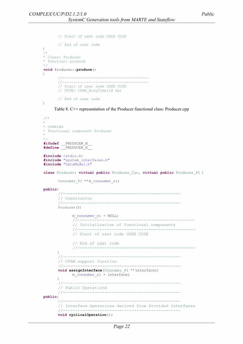
Table 8. C++ representation of the Producer functional class: Producer.cpp
/**
*
* COMPLEX
* Functional component Producer
*
*/
#ifndef __PRODUCER_H__
#define __PRODUCER_H__
#include <stdio.h>
#include "system_interfaces.h"
#include "DataModel.h"
class Producer: virtual public Producer_Cyc, virtual public Producer_PI {
Consumer_PI **m_consumer_ri;
public:
//------------------------------------------------
// Constructor
//------------------------------------------------
Producer(){
m_consumer_ri = NULL;
//------------------------------------------------
// Initialization of functional components
//------------------------------------------------
// Start of user code USER CODE
// End of user code
//------------------------------------------------
}
//------------------------------------------------
// CFAM support function
//------------------------------------------------
void assignInterface(Consumer_PI **interface){
m_consumer_ri = interface;
}
//------------------------------------------------
// Public Operations
//------------------------------------------------
public:
//------------------------------------------------
// Interface Operations derived from Provided Interfaces
//------------------------------------------------
void cyclicalOperation();
COMPLEX/UC/P/D2.1.2/1.0 Public
SystemC Generation tools from MARTE and Stateflow
Page 23
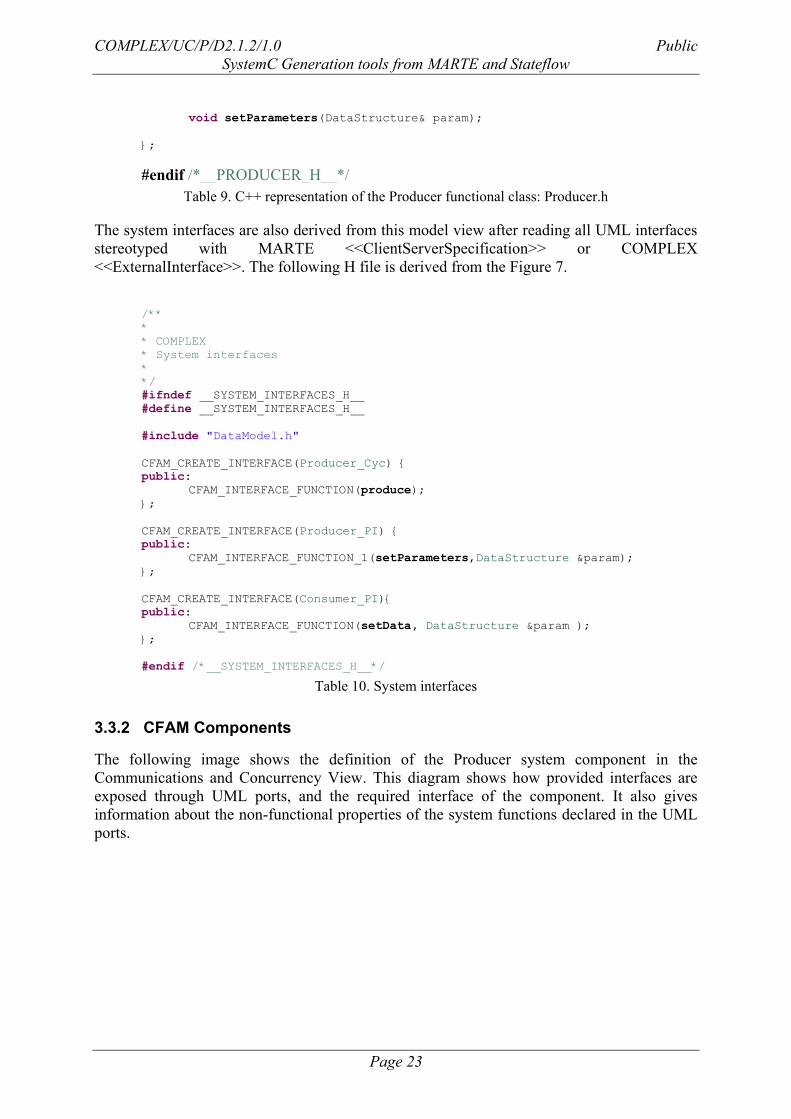
void setParameters(DataStructure& param);
};
#endif /*__PRODUCER_H__*/
Table 9. C++ representation of the Producer functional class: Producer.h
The system interfaces are also derived from this model view after reading all UML interfaces
stereotyped with MARTE <<ClientServerSpecification>> or COMPLEX
<<ExternalInterface>>. The following H file is derived from the Figure 7.
/**
*
* COMPLEX
* System interfaces
*
*/
#ifndef __SYSTEM_INTERFACES_H__
#define __SYSTEM_INTERFACES_H__
#include "DataModel.h"
CFAM_CREATE_INTERFACE(Producer_Cyc) {
public:
CFAM_INTERFACE_FUNCTION(produce);
};
CFAM_CREATE_INTERFACE(Producer_PI) {
public:
CFAM_INTERFACE_FUNCTION_1(setParameters,DataStructure ¶m);
};
CFAM_CREATE_INTERFACE(Consumer_PI){
public:
CFAM_INTERFACE_FUNCTION(setData, DataStructure ¶m );
};
#endif /*__SYSTEM_INTERFACES_H__*/
Table 10. System interfaces
3.3.2 CFAM Components
The following image shows the definition of the Producer system component in the
Communications and Concurrency View. This diagram shows how provided interfaces are
exposed through UML ports, and the required interface of the component. It also gives
information about the non-functional properties of the system functions declared in the UML
ports.
COMPLEX/UC/P/D2.1.2/1.0 Public
SystemC Generation tools from MARTE and Stateflow
Page 24
Figure 8. Communications and Concurrency View in the UML/MARTE model
The CFAM component is transformed into the file C++ files “Producer_comp.cpp” and
“Producer_comp.h”. Both are included in the “cfam_components” directory shown in Figure
5. /**
*
* COMPLEX
* System component Producer_comp
*
*/
#include "ControllerComponent.h"
Table 11. C++ representation of the Producer_Comp system component: Producer_comp.cpp
/**
*
* COMPLEX
* System component Producer_comp
*
*/
#ifndef __PRODUCER_COMP_H__
#define __PRODUCER_COMP_H__
#include <unistd.h>
#include <pthread.h>
#include "CFAM_macros.h"
#include "system_interfaces.h"
#include "Producer.h"
CFAM_CREATE_COMPONENT(Producer_comp)
CFAM_INHERIT_INTERFACES( public Producer_Cyc, public Producer_PI) {
INSTANTIATE_COMPONENT(Producer, m_producer);
// Declaration of the parameters of cyclical
// provided interfaces
// Periodic provided interface: produce
int m_time_produce;
// Declaration of the required interfaces
// of the component Producer_comp
CFAM_DECLARE_REQUIRED_INTERFACE(Consumer_PI, m_consumer_ri_1);
// Declaration of the non-cyclical
COMPLEX/UC/P/D2.1.2/1.0 Public
SystemC Generation tools from MARTE and Stateflow
Page 25
// provided interfaces of the component Producer_comp
CFAM_DECLARE_PROVIDED_INTERFACE(Producer_PI, m_producer_pi_1)
public:
CFAM_COMPONENT_CTOR(Producer_comp){
CFAM_INIT_FUNCITONALITY(Producer, m_producer);
// Periodic provided interface (Time in microseconds)
m_time_produce = 18000;
CFAM_ASSIGN_PROVIDED_INTERFACE(m_producer_pi_1, Producer_PI,
this);
}
// Required interface assigment
SPORADIC_FUNCTION_1(assignInterface, m_producer, Consumer_PI**);
// Provided interface: port cyclic
// Producer_Cyc
CYCLIC_FUNCTION(produce, m_producer);
// Provided interface: port producer_pi
// Producer_PI
SPORADIC_FUNCTION_1(setParameter, m_producer, DataStructure&);
CFAM_END_COMPONENT(Producer_comp)
#endif /*__PRODUCER_COMP_H__*/
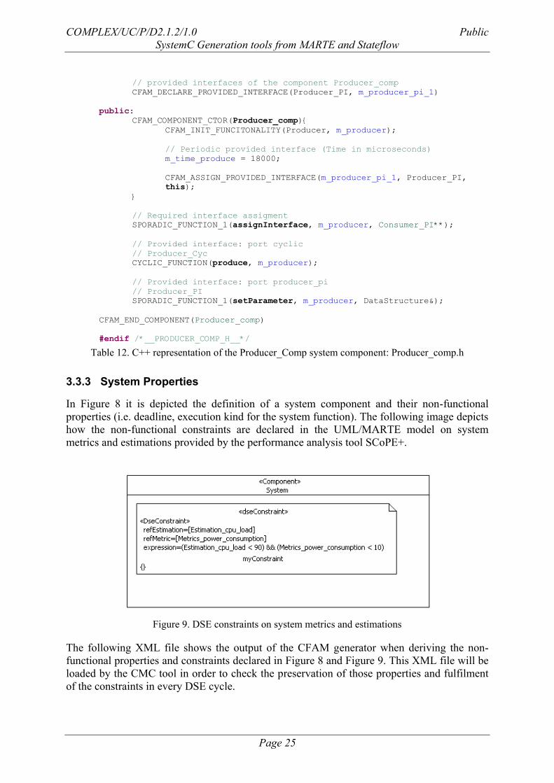
Table 12. C++ representation of the Producer_Comp system component: Producer_comp.h
3.3.3 System Properties
In Figure 8 it is depicted the definition of a system component and their non-functional
properties (i.e. deadline, execution kind for the system function). The following image depicts
how the non-functional constraints are declared in the UML/MARTE model on system
metrics and estimations provided by the performance analysis tool SCoPE+.
Figure 9. DSE constraints on system metrics and estimations
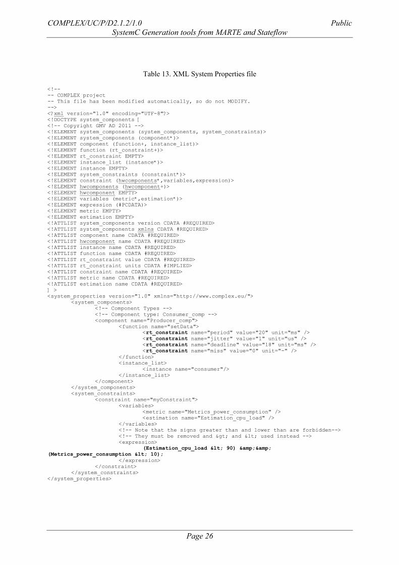
The following XML file shows the output of the CFAM generator when deriving the non-
functional properties and constraints declared in Figure 8 and Figure 9. This XML file will be
loaded by the CMC tool in order to check the preservation of those properties and fulfilment
of the constraints in every DSE cycle.
COMPLEX/UC/P/D2.1.2/1.0 Public
SystemC Generation tools from MARTE and Stateflow
Page 26
Table 13. XML System Properties file
<!--
-- COMPLEX project
-- This file has been modified automatically, so do not MODIFY.
-->
<?xml version="1.0" encoding="UTF-8"?>
<!DOCTYPE system_components [
<!-- Copyright GMV AD 2011 -->
<!ELEMENT system_components (system_components, system_constraints)>
<!ELEMENT system_components (component*)>
<!ELEMENT component (function+, instance_list)>
<!ELEMENT function (rt_constraint+)>
<!ELEMENT rt_constraint EMPTY>
<!ELEMENT instance_list (instance*)>
<!ELEMENT instance EMPTY>
<!ELEMENT system_constraints (constraint*)>
<!ELEMENT constraint (hwcomponents*,variables,expression)>
<!ELEMENT hwcomponents (hwcomponent+)>
<!ELEMENT hwcomponent EMPTY>
<!ELEMENT variables (metric*,estimation*)>
<!ELEMENT expression (#PCDATA)>
<!ELEMENT metric EMPTY>
<!ELEMENT estimation EMPTY>
<!ATTLIST system_components version CDATA #REQUIRED>
<!ATTLIST system_components xmlns CDATA #REQUIRED>
<!ATTLIST component name CDATA #REQUIRED>
<!ATTLIST hwcomponent name CDATA #REQUIRED>
<!ATTLIST instance name CDATA #REQUIRED>
<!ATTLIST function name CDATA #REQUIRED>
<!ATTLIST rt_constraint value CDATA #REQUIRED>
<!ATTLIST rt_constraint units CDATA #IMPLIED>
<!ATTLIST constraint name CDATA #REQUIRED>
<!ATTLIST metric name CDATA #REQUIRED>
<!ATTLIST estimation name CDATA #REQUIRED>
] >
<system_properties version="1.0" xmlns="http://www.complex.eu/">
<system_components>
<!-- Component Types -->
<!-- Component type: Consumer_comp -->
<component name="Producer_comp">
<function name="setData">
<rt_constraint name="period" value="20" unit="ms" />
<rt_constraint name="jitter" value="1" unit="us" />
<rt_constraint name="deadline" value="18" unit="ms" />
<rt_constraint name="miss" value="0" unit="-" />
</function>
<instance_list>
<instance name="consumer"/>
</instance_list>
</component>
</system_components>
<system_constraints>
<constraint name="myConstraint">
<variables>
<metric name="Metrics_power_consumption" />
<estimation name="Estimation_cpu_load" />
</variables>
<!-- Note that the signs greater than and lower than are forbidden-->
<!-- They must be removed and > and < used instead -->
<expression>
(Estimation_cpu_load < 90) &&
(Metrics_power_consumption < 10);
</expression>
</constraint>
</system_constraints>
</system_properties>
COMPLEX/UC/P/D2.1.2/1.0 Public
SystemC Generation tools from MARTE and Stateflow
Page 27
3.4 XML generator
A XML code generator has been developed and integrated in the COMPLEX plug-in. This
XML code is the input for the SCoPE tool in order to simulate and evaluate each
configuration of the design of the system to be implemented.
The COMPLEX MARTE2SCoPE generator (MARSCoPE in short) is a tool able to
automatically produce XML descriptions from UML models created under the COMPLEX
UML/MARTE methodology.
The main features of this generator are:
Full integration in Eclipse Helios COMPLEX as standalone plug-in.
Available also as a standalone Eclipse plug-in.
Generation of two different XML descriptions:
XML description of the HW platform and the SW applications.
XML description for the system design exploration.
Written in MTL (M2T), thus easily portable to different generation engines.
Generation of Headers reporting automatic generation.
The generator is available together with a manual [8], and a set of examples. The reference
manual introduces the aforementioned features, and additionally provides:
A user guide for the installation of the generation (standalone and COMPLEX
integrated version) and for its usage.
A detailed presentation of the COMPLEX UML/MARTE methodology.
A detailed explanation of the Transformation Rules to let the user know and
understand the supported UML/MARTE constructs, and which kind of code should
expect to be inferred.
A section enumerating the available examples and the features of the generator which
are put into practice by those examples.
MARSCoPE produces two XML files. In the first XML file HW platform architecture of the
system and the set of application performed by the system are descript namely
(Marte2xmlSD). The second XML file there are included all the design space exploration
(DSE) parameters that enables the system design exploration. Additionally, in this file there
are included a set of design rules in order to constraint all the possible design exploration
alternatives that can be covered by the DSE tools. This is the file Marte2SD.
COMPLEX/UC/P/D2.1.2/1.0 Public
SystemC Generation tools from MARTE and Stateflow
Page 28
3.4.1 Generation of the System Description (Marte2xmlSD)
The system specification is divided in a set of views that describes different system aspects to
be considered in the design process. The main system views used for the Marte2xmlSD are
the Platform View and the Architectural view.
Figure 10 Description of Platform Components
Figure 10 shows an example of a platform components description; a set of processors,
memories (RAM, ROM) and a bus have been modelled.
COMPLEX/UC/P/D2.1.2/1.0 Public
SystemC Generation tools from MARTE and Stateflow
Page 29
Figure 11 System architecture model
In the architectural view, there is specified the HW platform architecture (Figure 11) of the
system, the different application instances and the allocations of these applications instances
into HW platform resources.
Form the information captured in the Platform view and in the architectural view, the code
generator Marte2xmlSD produces the corresponding XML platform file.
Figure 12 A piece of XML code generated from examples Figure 10 and Figure 11
The generator Marte2xmlSD can produce an additional XML file. This file contains the
different communication paths that the designer wants to check in order to explore the
consequences in the performance estimation. Figure 13 shows an example about how to
specify the way that two processors are connected.
<HW_Platform>
<HW_Components>
<HW_Component category="processor" name="processador_1" … />
<HW_Component category="processor" name="processador_2" … />
<HW_Component category="processor" name="processador_3" … />
…
<HW_Component category="ram" name="RAM1" … />
… </HW_Components>
…
COMPLEX/UC/P/D2.1.2/1.0 Public
SystemC Generation tools from MARTE and Stateflow
Page 30
Figure 13 Modelled of the connection between two processors by means of a sequence diagram
The Figure 14 shows a piece of XML code generated from the connection specification
captured by means of the sequence diagram of Figure 13.
Figure 14 XML code generated from the connection specification of Figure 13
3.4.2 Generation of the Design Space exploration and rules (Marte2SD)
The Marte2SD generator produces the XML file includes the required information in order to
explore different design alternatives in the system specification. The design exploration is
mainly dealt with by two models elements, the DSE parameters and the DSE Rules. Figure 15
shows two examples of DSE parameters that denote that the attributes frequency and area of a
system element that will be explored in order to obtain the optimum results according to the
designer criterion.
Figure 15 DSE parameters specification
<interconnections>
<connection origin="process_1" target="process_4" link="ram2">
<component name="myBus">
<component name="ram2">
<component name="myBus">
</connection>
…
</interconnections>
COMPLEX/UC/P/D2.1.2/1.0 Public
SystemC Generation tools from MARTE and Stateflow
Page 31
Figure 16 DSE rule specification
The DSE rules reduce all the possible values that the DSE parameters can have, constraining
these possible values according to a logic expression. Figure 16 shows a DSE Rule to
configure the design exploration of the DSE parameters of Figure 15.
A piece of code generated from the previous model elements are shown in Figure 17 and
Figure 18.
Figure 17 A piece of XML code generated from the DSE parameters of Figure 15
Figure 18 A piece of XML code generated from the DSE rule ofFigure 16
3.5 Stimuli generator
The objective of the Stimuli Scenarios Definition process is to define a set of scenarios which
describe concrete behaviours of the external actors interfacing with the system. The stimuli
scenarios enable a DSE loop to simulate some significant execution scenarios to obtain
representative metrics. The stimuli scenarios are included in the verification view of the
COMPLEX methodology.
The main features of this generator MARTE2Stimuli are:
Full integration in Eclipse Helios COMPLEX as standalone plug-in.
<parameter name="__area_processador_1" type="string">
<item value="50"/>
<item value="100"/>
<item value="200"/>
</parameter>
…
<rule name="ProcessorRules">
<if>
<and>
<greater>
<parameter name="freq_processador_1"/>
<constant value="200"/>
</greater>
<greater-equal>
<parameter name="freq_processador_2"/>
<constant value="350"/>
<greater-equal>
</and>
…
COMPLEX/UC/P/D2.1.2/1.0 Public
SystemC Generation tools from MARTE and Stateflow
Page 32
Available also as a standalone Eclipse plug-in.
Generation of set of C/C++ files according to the stimuli scenarios modelled
Written in MTL (M2T), thus easily portable to different generation engines
Generation of Headers reporting automatic generation
The generator is available together with a manual [9], and a set of examples. The reference
manual introduces the aforementioned features, and additionally provides:
A user guide for the installation of the generation (standalone and COMPLEX
integrated version) and for its usage.
A detailed presentation of the COMPLEX Stimuli Scenarios methodology.
A detailed explanation of the Transformation Rules to let the user know and
understand the supported UML/MARTE constructs, and which kind of code should
expect to be inferred.
A section enumerating the available examples and the features of the generator which
are put into practice by those examples.
3.5.1 Generation of Scenarios
Each stimuli scenario is modelled as a UML package which has been identified by means of
the COMPLEX stereotype <<Scenario>>.
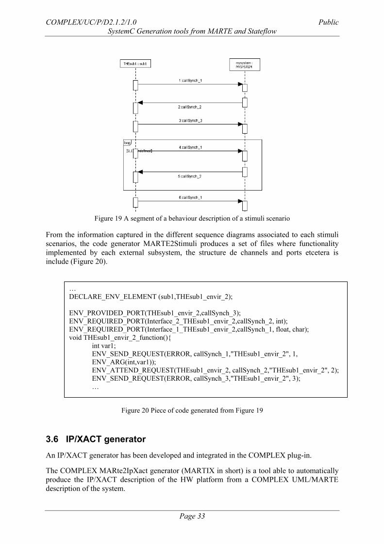
3.5.2 Generation of the Interaction of Interaction (Sequence) Diagrams
The behaviour carried out in each stimuli scenario is described by means of a sequence
diagram. In this diagram, there are included the external subsystems that interact with the
system. The information transmitted is modelled through message that represents service calls
provided by a set of external interfaces (Figure 19).
COMPLEX/UC/P/D2.1.2/1.0 Public
SystemC Generation tools from MARTE and Stateflow
Page 33
Figure 19 A segment of a behaviour description of a stimuli scenario
From the information captured in the different sequence diagrams associated to each stimuli
scenarios, the code generator MARTE2Stimuli produces a set of files where functionality
implemented by each external subsystem, the structure de channels and ports etcetera is
include (Figure 20).
Figure 20 Piece of code generated from Figure 19
3.6 IP/XACT generator
An IP/XACT generator has been developed and integrated in the COMPLEX plug-in.
The COMPLEX MARte2IpXact generator (MARTIX in short) is a tool able to automatically
produce the IP/XACT description of the HW platform from a COMPLEX UML/MARTE
description of the system.
…
DECLARE_ENV_ELEMENT (sub1,THEsub1_envir_2);
ENV_PROVIDED_PORT(THEsub1_envir_2,callSynch_3);
ENV_REQUIRED_PORT(Interface_2_THEsub1_envir_2,callSynch_2, int);
ENV_REQUIRED_PORT(Interface_1_THEsub1_envir_2,callSynch_1, float, char);
void THEsub1_envir_2_function(){
int var1;
ENV_SEND_REQUEST(ERROR, callSynch_1,"THEsub1_envir_2", 1,
ENV_ARG(int,var1));
ENV_ATTEND_REQUEST(THEsub1_envir_2, callSynch_2,"THEsub1_envir_2", 2);
ENV_SEND_REQUEST(ERROR, callSynch_3,"THEsub1_envir_2", 3);
…
COMPLEX/UC/P/D2.1.2/1.0 Public
SystemC Generation tools from MARTE and Stateflow
Page 34
The main features of this generator are:
Full integration in Eclipse Helios COMPLEX plug-in
Available also as an standalone Eclipse plug-in
Two generation “levels”
o IP/XACT sub-set for high-level estimation tools (SCoPE+)
o IP/XACT for lower-level estimation tools (which later enables to feed
Magillem code generators)
Written in MTL (M2T), thus easily portable to different generation engines
Generation of Headers reporting automatic generation
Generation of XML comments to let track the generation process
The generator is available together with a manual [4], and a set of examples. Further
introductory information can be found in [6][7].
The reference manual introduces the aforementioned features, and additionally provides:
A user guide for the installation of the generation (standalone and COMPLEX
integrated version) and for its usage.
A detailed explanation of the Transformation Rules to let the user know and
understand the supported UML/MARTE constructs, and which kind of code should
expect to be inferred.
A section enumerating the available examples and the features of the generator which
are put into practice by those examples.
A section documenting the error, warnings and information reported by the generator.
As mentioned, the generator can be installed in a standalone mode, as it is shown in as well as
integrated within the COMPLEX menu. The standalone mode installs the Martix menu and a
fast access generation button.
Menu of the COMPLEX plug-in Menu for the standalone plug-in
Fast Generation
Button
Figure 21. Eclipse Helios Instance with both, the COMPLEX plug-in and the standalone MARTIX
plug-in installed.
COMPLEX/UC/P/D2.1.2/1.0 Public
SystemC Generation tools from MARTE and Stateflow
Page 35
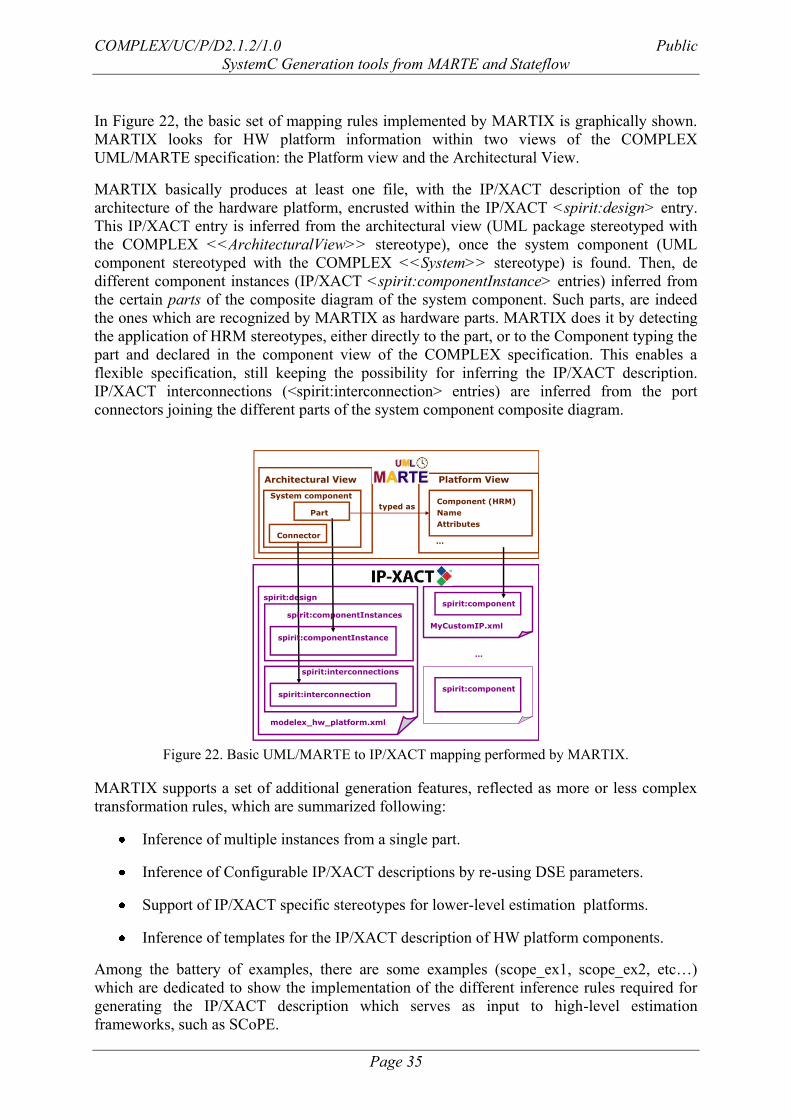
In Figure 22, the basic set of mapping rules implemented by MARTIX is graphically shown.
MARTIX looks for HW platform information within two views of the COMPLEX
UML/MARTE specification: the Platform view and the Architectural View.
MARTIX basically produces at least one file, with the IP/XACT description of the top
architecture of the hardware platform, encrusted within the IP/XACT <spirit:design> entry.
This IP/XACT entry is inferred from the architectural view (UML package stereotyped with
the COMPLEX <<ArchitecturalView>> stereotype), once the system component (UML
component stereotyped with the COMPLEX <<System>> stereotype) is found. Then, de
different component instances (IP/XACT <spirit:componentInstance> entries) inferred from
the certain parts of the composite diagram of the system component. Such parts, are indeed
the ones which are recognized by MARTIX as hardware parts. MARTIX does it by detecting
the application of HRM stereotypes, either directly to the part, or to the Component typing the
part and declared in the component view of the COMPLEX specification. This enables a
flexible specification, still keeping the possibility for inferring the IP/XACT description.
IP/XACT interconnections (<spirit:interconnection> entries) are inferred from the port
connectors joining the different parts of the system component composite diagram.
Architectural View
Part
spirit:design
Platform View
Component (HRM)
Name
Attributes
Connector
spirit:componentInstances
spirit:interconnections
spirit:component
spirit:component
…
spirit:componentInstance
spirit:interconnection
System component
…
modelex_hw_platform.xml
MyCustomIP.xml
typed as
Figure 22. Basic UML/MARTE to IP/XACT mapping performed by MARTIX.
MARTIX supports a set of additional generation features, reflected as more or less complex
transformation rules, which are summarized following:
Inference of multiple instances from a single part.
Inference of Configurable IP/XACT descriptions by re-using DSE parameters.
Support of IP/XACT specific stereotypes for lower-level estimation platforms.
Inference of templates for the IP/XACT description of HW platform components.
Among the battery of examples, there are some examples (scope_ex1, scope_ex2, etc…)
which are dedicated to show the implementation of the different inference rules required for
generating the IP/XACT description which serves as input to high-level estimation
frameworks, such as SCoPE.
COMPLEX/UC/P/D2.1.2/1.0 Public
SystemC Generation tools from MARTE and Stateflow
Page 36
Other examples (toy example, IP/XACT soclib example) are oriented to show the inference of
more general IP/XACT descriptions, which serve for the generation of lower-level
performance executable models.
The following code excerpt is an example of the XML comments inferred by MARTIX and
which serves for the offline tracking of its generation process:
…
<!-- MARTIX Msg: Extraction of HW Architecture from System Component SystemComp --
>
<!-- MARTIX Msg: Detected Platform Components: xilkernel_smp APB_AHB_Bridge AHB
APB elinux ARM11 CameraDev SteerCtrlDev ublaze -->
<!-- MARTIX Msg: where the following are HW components: AHB APB_AHB_Bridge
APB SteerCtrlDev CameraDev ARM11 ublaze -->
<!-- MARTIX Msg:
************************************************************** -->
<!-- MARTIX Msg: 7 UML/MARTE Component Instances Detected:
-->
<!-- MARTIX Msg:
************************************************************** -->
<spirit:componentInstances>
<!-- MARTIX Msg: IP/XACT Component Instance generated from HW Component instance
bus2 of type APB -->
<spirit:componentInstance>
<spirit:instanceName>bus2</spirit:instanceName>
…
All the tracking information is reported as a MARTIX message, within the XML comment.
MARTIX provides warnings for the situations where there is a possibility for an ambiguity or
undesired inference, but which does not prevent the inference it self. MARTIX provides error
messages when the inference cannot be done, for instance, because a required construct is not
present (e.g., the system component) or because there is an incompatibility.
3.7 Design Space Exploration plug-in
The COMPLEX DSE plug-in is responsible for the integration of the COMPLEX Eclipse
Application, the high-level estimation tool SCoPE+ and the design exploration tool MOST.
This plug-in executes the DSE loop seamlessly from the Eclipse Environment by generating
the necessary executable scripts that executes MOST and SCoPE+ tools.
The COMPLEX DSE plug-in also forwards the output of the SCoPE+ and MOST tools to the
Eclipse console so that the user can always verify the results of the simulation and DSE
COMPLEX/UC/P/D2.1.2/1.0 Public
SystemC Generation tools from MARTE and Stateflow
Page 37
execution. Moreover, the results of the DSE loop are imported to the Eclipse project for its
later analysis by the user.
The main features of this DSE engine are summarized bellow:
Full integration in Eclipse framework by means of the extension mechanism for
application functionality described in section 3.1.
Generation of the scripts that executes the MOST tool for performing the DSE
exploration loop.
Generation of the scripts that wraps the integration of the MOST, SCoPE+ and
COMPLEX Model Checker (CMC) tools. The later was introduced in the DSE loop in
order to verify the preservation of the non-functional properties during the simulation.
For further details, please refer to section 5.1 to have more information about how
CMC integrates with the estimation and exploration tools.
Executes the DSE loop and forwards the outputs to the Eclipse console.
Finally, imports the results of the DSE loop and imports them to the Eclipse project. If
user selected other project output directory, the results of the DSE will be copied to
the selected analysis directory for results.
The COMPLEX DSE plug-in produces the following outputs:
The full data base result of the execution of the DSE loop: it identifies the file with the
date and time when it was imported.
The pareto data base result of the execution of the DSE loop: it identifies the file with
the date and time when it was imported.
COMPLEX/UC/P/D2.1.2/1.0 Public
SystemC Generation tools from MARTE and Stateflow
Page 38
4 Generation of Executable Models from Stateflow
Matlab, Simulink and Stateflow are widely used model-based design tools provided by
MathWorks. They find applications in areas such as automotive controls, avionics, and digital
signal processing for telecommunications. They provide the designer with a platform-
independent model, which can take the form of algorithmic description (by using the M
language), or block diagrams (by using Simulink blocks), or finite state machines represented
in Stateflow. All these descriptions can work together, via defined interfaces, for both
simulation and target code generation. Simulation can use both continuous and discrete time
semantics. Code generation is performed by language translators, such as Embedded Coder,
Real Time Workshop, HDL Coder or Stateflow Coder, which generate either ANSI C code, or
synthesizable HDL code, for HW or SW implementation.
As shown in Figure 23 Stateflow machines arrange Stateflow objects in a hierarchy based on
containment. That is, one Stateflow object can contain other Stateflow objects. The highest
object in Stateflow hierarchy is the Stateflow machine. This object contains all other
Stateflow objects in a Simulink model. The Stateflow machine contains all the charts in a
model. In addition, the Stateflow machine for a model can contain its own data and target
objects. Similarly, charts can contain state, box, function, data, event, transition, junction, and
note objects. Continuing with the Stateflow hierarchy, states can contain all these objects as
well, including other states. You can represent state hierarchy with superstates and substates.
A transition out of a superstate implies transitions out of any of its active substates.
Transitions can cross superstate boundaries to specify a substate destination. If a substate
becomes active, its parent superstate also becomes active. You can organize complex charts
by defining a containment structure. A hierarchical design usually reduces the number of
transitions and produces neat, manageable charts.
Figure 23 Stateflow hierarchy
Every state (and chart) has a decomposition that dictates what kind of substates it can contain.
All substates of a superstate must be of the same type as the superstate‟s decomposition.
Decomposition for a state can be exclusive (OR) or parallel (AND). These types of
decomposition are described in the following topics. Exclusive (OR) state decomposition for
COMPLEX/UC/P/D2.1.2/1.0 Public
SystemC Generation tools from MARTE and Stateflow
Page 39
a superstate (or chart) is graphically indicated when its substates have solid borders. Exclusive
(OR) decomposition is used to describe system modes that are mutually exclusive. When a
state has exclusive (OR) decomposition, only one substate can be active at a time. The
children of exclusive (OR) decomposition parents are OR states. The children of parallel
(AND) decomposition parents are parallel (AND) states. Parallel (AND) state decomposition
for a superstate (or chart) is graphically indicated when its substates have dashed borders.
This representation is appropriate if all states at that same level in the hierarchy are always
active at the same time. The activity within parallel states is essentially independent.
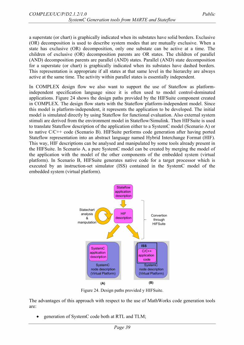
In COMPLEX design flow we also want to support the use of Stateflow as platform-
independent specification language since it is often used to model control-dominated
applications. Figure 24 shows the design paths provided by the HIFSuite component created
in COMPLEX. The design flow starts with the Stateflow platform-independent model. Since
this model is platform-independent, it represents the application to be developed. The initial
model is simulated directly by using Stateflow for functional evaluation. Also external system
stimuli are derived from the environment model in Stateflow/Simulink. Then HIFSuite is used
to translate Stateflow description of the application either to a SystemC model (Scenario A) or
to native C/C++ code (Scenario B). HIFSuite performs code generation after having ported
Stateflow representation into an abstract language named Hybrid Interchange Format (HIF).
This way, HIF descriptions can be analysed and manipulated by some tools already present in
the HIFSuite. In Scenario A, a pure SystemC model can be created by merging the model of
the application with the model of the other components of the embedded system (virtual
platform). In Scenario B, HIFSuite generates native code for a target processor which is
executed by an instruction-set simulator (ISS) contained in the SystemC model of the
embedded system (virtual platform).
HIF
description
SystemC
node description
(Virtual Platform)
SystemC
application
description
(A) (B)
Stateflow
application
description
Convertion
through
HIFSuite
Statechart
analysis
&
manipulation
SystemC
node description
(Virtual Platform)
ISS
C/C++
application
code
Figure 24. Design paths provided y HIFSuite.
The advantages of this approach with respect to the use of MathWorks code generation tools
are:
generation of SystemC code both at RTL and TLM;
COMPLEX/UC/P/D2.1.2/1.0 Public
SystemC Generation tools from MARTE and Stateflow
Page 40
support for parallel state charts to generate multi-threaded models (in SystemC and
C/C++);
presence of advanced analysis functionality, e.g., state reachability, state equivalence,
dependability analysis, model verification;
availability of automated mechanisms to perform transformations on the state charts
(e.g., state reduction, chart abstraction).
In the next sub-sections both SystemC generation and C/C++ generation are briefly
introduced; for a detailed description of the tool, online documentation is available. In
particular, documentation about the HIFSuite tool can be found at
http://www.hifsuite.com/presentations/HIFSuite_UG.pdf
while specific documentation on SystemC and C/C++ generation can be found at
http://www.hifsuite.com/presentations/sf2cpp.pdf
4.1 Generation of SystemC
The semantic elements of the Stateflow model (e.g., states, junctions, transitions) are
extracted from the MDL file and represented by the HIF language by using an appropriate
front-end tool named SF2HIF.
The HIF format preserves the functional behaviour of the statecharts obtained from Stateflow;
the parallel behaviour of AND states is also preserved. In the HIF domain different tools can
be used to verify and manipulate the statecharts. For instance, state coverage can be analysed
and abstraction can be performed by grouping together equivalent states and low-level states.
State manipulation and abstraction could be useful to optimize some properties of the system
(e.g., power consumption) or to speed up simulation of SystemC models.
A back-end tool named HIF2CPP, with appropriate command line options, generates a
SystemC model of the original statechart. The SystemC model can be both at RTL and TLM
depending on the detail level of the Stateflow model and on the abstraction process eventually
performed on the HIF representation.
The user can choose to generate either multi-thread or single-thread code depending on the
modelling needs. Multi-thread behaviour is obtained by using SystemC sc_thread. Single-
thread code is generated by serializing AND states according to the execution order specified
in the original Stateflow model.
4.2 Generation of (C/C++)
The semantic elements of the Stateflow model (e.g., states, junctions, transitions) are
extracted from the MDL file and represented by the HIF language by using an appropriate
front-end tool named SF2HIF.
COMPLEX/UC/P/D2.1.2/1.0 Public
SystemC Generation tools from MARTE and Stateflow
Page 41
The HIF format preserves the functional behaviour of the statecharts obtained from Stateflow;
the parallel behaviour of AND states is also preserved. In the HIF domain different tools can
be used to verify and manipulate the statecharts. For instance, state coverage can be analysed
and abstraction can be performed by grouping together equivalent states and low-level states.
State manipulation and abstraction could be useful to optimize some properties of the system
(e.g., power consumption) or to speed up simulation of SystemC models.
A back-end tool named HIF2CPP, with appropriate command line options, generates ANSI
C/C++ code corresponding to the behaviour of the statechart, implemented as a set of nested
switch and if statements representing the behaviour of the various states and super-states,
depending on and affecting the value of external and internal signals, as well as depending on
timeouts and on entering and leaving other states of the statechart.
The user can choose to generate either multi-threaded or single-threaded code depending on
the target architecture. Multi-threaded code is generated by following the standard of POSIX
threads. Single-threaded code is generated by serializing AND states according to the
execution order specified in the original Stateflow model.
COMPLEX/UC/P/D2.1.2/1.0 Public
SystemC Generation tools from MARTE and Stateflow
Page 42
5 Non-Functional Constraints in the COMPLEX flow
This section explains the support given in COMPLEX flow for non-functional constraints, not
only at the capture of the model, but also for the rest of the flow (generation, simulation,
exploration…).
It must be left clear that this work:
Does not addresses a complete support (which is left for other projects)
That has been done only for the MARTE related flow
5.1 Capturing of non-functional Constraints in the MARTE model
The document [3] defined a system-level specification methodology supporting the
description of extra functional properties following a component-based engineering approach.
These properties are expressed in terms of system-level constraints by means of MARTE and
COMPLEX profile stereotypes. These constraints will be verified during the high-level
system simulation and design exploration by the tools implemented in task 2.1.
Two different kinds of system-level constraints can be distinguished from the system design
perspective:
Real-Time (RT) constraints in system functions.
DSE constraints on system metrics and estimations provided by the SCoPE+ tool
5.1.1 Real-time Constraints on system functions
Document [3] defines different model viewpoints in the UML/MARTE model to focus the
attention of the system designers in specific aspects of the system. The model view devoted to
the declaration of the real-time properties of the system function is the concurrency and
communications view.
In this view, system designers declare the different components that form part of the system
application, what functions are implemented by those components, and what extra-functional
properties are associated to those functions. The following list identifies the list of extra-
functional properties that the user can provide in the UML model:
Execution pattern of the system function: indicates whether the function is executed
periodically or sporadically. In case of periodic functions, it also gives information
about the period and the possible jitter. In the case of sporadic functions, it provides
information about the minimum and maximum interarrival time, and the possible
associated jitter in previous values.
Deadline of the system function: defines the absolute deadline associated to the
execution of a system function.
Percentage of acceptance for missing deadlines for a particular system function. It
could be zero, therefore it is considered as hard real time.
Priority of execution of the designated system function.
COMPLEX/UC/P/D2.1.2/1.0 Public
SystemC Generation tools from MARTE and Stateflow
Page 43
The following image depicts how these extra-functional properties are specified in the
UML/MARTE model:
Figure 25. Extra-functional properties at application level
The UML comment stereotyped with <<RtSpecification>> provides information about the
system functions exposed in the consumer_pi port. This RT specification is referenced by the
UML port consumer_pi from the MARTE stereotype <<RtFeature>>. It provides the
following information:
occKind: provides the execution partner for the designated function, following the
Value Specification Language described in the MARTE standard [14].
absDl: provides the absolute deadline of the designated system function, following the
Value Specification Language described in the MARTE standard [14].
miss: represents the percentage of missing deadlines for the designated function.
priority: defines the initial execution priority of the system function.
5.1.2 DSE constraints on system metrics and estimations
The DSE constraints on system metrics and estimations are provided in the architectural view
of the UML/MARTE model by means of the use of COMPLEX stereotype
<<DseConstraint>>. The DSE constraints might be applied to system metrics, estimations or
on both at the same time. A Java-like expression relates the different metrics and estimations
to create a logic expression that will be evaluated during design exploration loop.
DSE constraints are defined UML constraints stereotyped with <<DseConstraint>>. This
constraints may be linked to instances of HW elements in the system architecture. If so, it
COMPLEX/UC/P/D2.1.2/1.0 Public
SystemC Generation tools from MARTE and Stateflow
Page 44
indicates that constraint is only applicable to the constrained component. The following image
depicts how these extra-functional properties are specified in the UML/MARTE model:
Figure 26. DSE constraints on system metrics and estimations
The constraint is valid only if the design space point fulfils that the CPU load is lower than
90% and the power consumption is lower than 10 mW. Due to the fact that there is no
constrained element, this constraint applies to all processing nodes defined in the architecture.
Regarding the different non-functional properties that are supported in the UML/MARTE
model, the following list defines the different system metrics and estimations, as well as their
default units, which are provided by the SCoPE+ tool:
Table 14 : list of system metrics
Metric Name Default Unit
System_area mm2
Execution_cycles cycle
Latency second
Instruction_count instruction
Clock_per_instruction Cycle/instruction
Intructions_per_clock Instruction/cycle
MIPS Million of
instruction/second
Hit_Rate percentage
Memory_stall_cycle cycle
AMAT second
Bus_bandwidth Bit/s
Network_Aggregate_bandwidth Bit/s
COMPLEX/UC/P/D2.1.2/1.0 Public
SystemC Generation tools from MARTE and Stateflow
Page 45
Transport_latency seconds
Energy_consumption Jules
Power_consumption Watt
Table 15 : list of estimations
Estimation Units
Number of thread
switches
N/A
Number of context
switches
N/A
Runnig Time ns
Use of cpu ns
Instruction executed N/A
Instruction cache misses N/A
Core energy nJ
Core power mW
Instruction cache energy nJ
Instruction cache power mW
Task WCET ns
Task min activation time ns
Task max activation ns
5.2 Using of Non-Functional Constraints in the MARTE-related COMPLEX flow
Due to the fact that the system metrics supported by SCoPE+ are considered at system level,
they do not provide useful information to determine whether the application extra-functional
properties are satisfied or not. Moreover, the estimations provided by SCoPE+ are referred to
the platform computational nodes and the tasks they are hosting; therefore they provide
enough information to enable the verification of the model properties. However, they cannot
be part of the DSE loop because the interaction between MOST and SCoPE+ only involves
system and user-defined metrics.
In order to overcome these issues, the COMPLEX Model Checker (CMC) application was
developed in order to integrate the verification of the extra-functional constraints within the
COMPLEX/UC/P/D2.1.2/1.0 Public
SystemC Generation tools from MARTE and Stateflow
Page 46
DSE loop and verify that both extra-functional properties and DSE constraints are fulfilled
during the simulation. The following image shows the interaction between the COMPLEX
Eclipse Application (CEA) modelling framework, the SCoPE+ tool and the exploration tool
MOST within the DSE loop. The COMPLEX Model Checker (CMC) stays in the middle of
SCoPE+ and MOST analyzing the results of the high-level simulation and checking those
results against the system extra-functional properties and DSE constraints expressed in the
UML/MARTE model.
XML
Design
Space
XML System
Configuration
XML System
Metrics
MOST
SCoPE+
COMPLEX
Eclipse
Application
(CEA)
XML
System
Description
XML System
Estimations
1
12
4
MOST
Exploration
Script1
XML SW
components
3
XML
System
Properties
COMPLEX
Model Checker
(CMC)
1
Figure 27. Verification of the extra-functional properties in the DSE loop
From the UML/MARTE model the following information must be extracted and stored in an
XML file.
Extra-functional properties of system functions: deadline, jitter, period (inter-arrival
time for sporadic functions), and miss percentage.
DSE constraints combining both estimations and metrics into a boolean-like
expression to evaluate the feasibility of the architecture.
Estimations are always local to processing nodes or bus components according to the
SCoPE+ user manual (pending to be updated). Therefore the DSE constraint might be
either local to the processing node or global to the architecture. The evaluation of the
expression will take into account whether the constraint is only applicable to a HW
component (either processing node or bus component) or must be evaluate globally.
The interaction between CEA, SCoPE+, MOST and CMC follows the following steps:
1. This first step corresponds with the generation of the MOST exploration script,
XML Design Space and the XML System Description files from the
UML/MARTE model. This transformation is under the responsibility of the
COMPLEX/UC/P/D2.1.2/1.0 Public
SystemC Generation tools from MARTE and Stateflow
Page 47
CEA tool. This tool also generates the XML System Properties file that
describes the extra-functional and DSE constraints defined in the system
model.
2. Once the DSE loop starts, the MOST tool provides the XML System
Configuration to the SCoPE+ tool. This file gives information of the DSE
point to be simulated.
3. Then, SCoPE+ outputs the XML SW components file, the XML System
estimations file and the XML System Metrics to the MOST tool. The first
describes the software-related estimations for each system function, while the
second represents the estimations per processing nodes. Finally, the last file
represents the system-level metrics that guides the exploration loop.
4. At last, the CMC loads the XML SW Estimations, the XML System
Estimations and XML System Metrics, and check them against the values in
the XML System Properties file. If any of the estimations show a violation of
any extra-functional property, the CMC overwrites the XML System Metrics
file with the following content:
<?xml version="1.0" encoding="UTF-8"?>
<simulator_output_interface xmlns="http://www.multicube.eu/" version="1.4">
<error reason="Consistency or feasibility violation" kind="non-fatal"/>
</simulator_output_interface>
Table 16. XML System Metrics file after CMC execution
COMPLEX/UC/P/D2.1.2/1.0 Public
SystemC Generation tools from MARTE and Stateflow
Page 48
6 Acronym List
Acronym Stands for
CEA COMPLEX Eclipse Application
CMC COMPLEX Model Checker
CPU Central Processing Unit
DSE Design Space Exploration
MARTE Modelling and Analysis of Real-Time and
Embedded systems
MDA Model Driven Architecture
MTL Model to Text Language
PDM Platform Description Model
PIM Platform Independent Model
PSM Platform Specific Model
SW Software
UML Unified Modelling Language
COMPLEX/UC/P/D2.1.2/1.0 Public
SystemC Generation tools from MARTE and Stateflow
Page 49
7 References
[1] "Description of Work". COMPLEX – COdesign and power Management in Platform-
based design-space EXploration, FP7-ICT-2009- 4 (247999), 2009.
[2] “Definition of application, stimuli and platform specification, and definition of tool
interfaces”. COMPLEX – COdesign and power Management in Platform-based design-
space EXploration, D1.2.1, version 1.1.1
[3] F. Ferrero, R. Valencia, F.Herrera, E.Villar, L. Lavagno, D. Quaglia. “System
Specification Methodology using MARTE and Stateflow”. COMPLEX – COdesign and
power Management in Platform-based design-space Exploration, Deliverable D2.1.1,
version 1.0. December, 2010.
[4] Carlo Brandolese, Gianluca Palermo, William Fornaciari (PoliMi), Fernando Herrera,
Eugenio Villar (UC), Francisco Ferrero, Raúl Valencia (GMV), Bart Vanthournout
(SNPS). “Preliminary report on embedded software estimation and model generation”.
COMPLEX – COdesign and power Management in Platform-based design-space
Exploration, Deliverable D2.2.1, version 1.0. December, 2010.
[5] F.Herrera and E.Villar. “Automatic Generation of the IP/XACT description of the HW
platform from UML/MARTE SystemC Specifications (The COMPLEX Approach)”.
Version 0.1. June, 2011.
[6] F.Herrera, E. Villar. “Generation of Abstract IP/XACT Platform Descriptions from
UML/MARTE for System-Level Performance Estimation. Towards a MARTE to
IP/XACT Generation Framework of HW platform descriptions for a DSE Multi-level
Performance Estimation Framework”. In 2nd
Workshop on Model-based design of
Embedded Systems, M-BED2011. In Grenoble, March, 2011.
[7] F.Herrera and E.Villar. “A Framework for the Generation from UML/MARTE
Models of IP/XACT HW Platform Descriptions for Multi-Level Performance
Estimation”. Submitted to the Forum of Specification Languages 2011.
[8] P.Peñil, F.Herrera, E.Villar. ”Automatic Generation of SCoPE XML description of the
HW platform, SW platform and Design Space Exploration from a COMPLEX
UML/MARTE Specification”. Version 0.1. June, 2011.
[9] P.Peñil, F.Herrera, E.Villar. ”Automatic Generation of SystemC Stimuli Scenario
from COMPLEX UML/MARTE Specification”. Version 0.1. June, 2011.
[10] “MDA Guide”. (OMG/2003-06-12), version 1.0.1.
[11] “UML2 infrastructure”. (OMG/2009-02-04), version 2.3.
[12] “UML2 superstructure”. (OMG/2009-02-02), version 2.3.
[13] “MOF Model to Text Transformation Language (MOFM2T)”. (OMG/2008-01),
version 1.0.
[14] “MARTE specification”. (OMG/2009-11-02), version 1.0.
[15] “OCL Specification). (OMG/ 2006-05-01), version 2.0.
[16] “SystemC Core Language”. (OSCI/2007-03-14), version 2.2.
[17] Schema WG of The SPIRIT Consortium. “IP-XACT v1.4: A specification for XML
meta-data and tool interfaces”. March, 12th. 2008.
[18] Papyrus MDT tool (http://www.eclipse.org/modeling/mdt/papyrus/ ), version 0.7.0
[19] MARTE profile for Papyrus (http://www.papyrusuml.org/), version 1.0
[20] Eclipse framework (http://www.eclipse.org/), version 3.6 (Helios)
[21] Acceleo (http://www.acceleo.org/), version 3.0.2
COMPLEX/UC/P/D2.1.2/1.0 Public
SystemC Generation tools from MARTE and Stateflow
Page 50
[22] User Manual for M3P SCoPE Plug-in: XML Management for DSE
(http://www.teisa.unican.es/gim/en/scope/source.html ), version 1.0.5
[23] Multicube Explorer User Manual.
http://home.dei.polimi.it/zaccaria/multicube_explorer_v1/Documentation.html ), version
1.1
[24] Magillem Generator Studio, http://www.magillem.com/eda/
[25] S. Taha, A. Radermacher, S. Gerard Jean-Luc Dekeeyser. MARTE: UML-based
Hardware Design from Modeling to Simulation. FDL‟2007, Barcelona, Spain, September
2007.
[26] P. Boulet, P. Marquet, E. Piel, J. Taillard. “Repetitive Allocation Modelling with
MARTE”. In Proceedings of FDL‟07. Barcelona, Sept. 2007.
[27] E. Piel, R.B.Atitallah, P.Marquet, S.Meftali, S. Niar, A. Etien, J.L.Dekeyser, P.
Boulet. “Gaspard2: from MARTE to SystemC Simulation. In Design, Automation and
Test in Europe (DATE 08), Munich, Germany, March 2008.
[28] J.L.Dekeyser, A. Gamatié, A. Etien, R.B.Atitallah, P. Boulet. "Using the UML Profile
for MARTE to MPSoC Co-Design". In First International Conference on Embedded
Systems & Critical Applications (ICESCA'08), Tunis, Tunisia, May 2008.
[29] J. Vidal, F. de Lamotte, G. Gogniat, P. Soulard, J.P. Diguet. “A Code-Design
Approach for Embedded System Modeling and Code Generation with UML and
MARTE”. In Design, Automation & Test in Europe Conference, DATE‟09. Dresden.
March, 2009.
[30] D. Aulagier, A. Koudri, S. Lecomte, P. Soulard, J.Champeau, J.Vidal, G.Perrouin,
P.Leray. “SoC/SoPC development using MDD and MARTE profile”. In Model Driven
Engineering for Distributed Real-time Embedded Systems ISTE (Ed.) (2009).
[31] A. W. Liehr, H. S. Rolfs, K. J. Buchenrieder, and U. Nageldinger. “Generating
MARTE Allocation Models from Activity Threads” in “Languages for Embedded
Systems and their Applications”. Lecture Notes in Electrical Engineering, 2009, Volume
36, Part I, 43-56.
[32] A. W. Liehr, H. S. Rolfs, K. J. Buchenrieder, and U. Nageldinger. “Visual Feedback
for Design-Space Exploration with UML MARTE“. International Conference on
Innovations in Information Technology, 2008. IIT 2008. Dec., 2009.
[33] M.Mura, L.G.Murillo, M.Prevostini. “Model-based Design Space Exploration for
RTES with SysML and MARTE”. In proceedings of the Forum of Specification and
Design Languages 2008, FDL‟08. Stuttgart, Germany. 2008.
[34] P. Ulbrich, C. Elsner†, M. Hoffmann, R. Schmid, W. Schröder-Preikschat ”Using
MARTE in Code-centric Real-time Projects Providing Evolution Support”. In
Proceedings of DATE, 2010. March, 2010. Dresden, Germany. Available online in Aug.
2010 in http://www4.informatik.uni-
erlangen.de/Publications/2010/ulbrich_etal_date2010_mbed.pdf.
[35] P. Peñil, H. Posadas, E.Villar. “Formal Modeling for UML-MARTE Concurrency
Resources”. UML&AADL. 15th IEEE Int. Conf. on Engineering of Complex Computer
Systems. Oxford. March, 2010.
[36] P. Andersson, M. Host. “UML and SystemC- A comparison and Mapping Rules for
Automatic Code Generation”. In Embedded Systems Specification and Design Languages.
Lecture Notes in electrical Engineering., 2008, V10, III, pags. 199-209.
COMPLEX/UC/P/D2.1.2/1.0 Public
SystemC Generation tools from MARTE and Stateflow
Page 51
[37] P. Peñil, J. Medina, H. Posadas, E. Villar. “Generating heterogeneous executable
specifications in SystemC from UML/MARTE models”. Innovations in System Software
Engineering (2010) 6:65–71. DOI 10.1007/s11334-009-0105-4.
[38] P.Peñil, F.Herrera, and E.Villar. “Formal Foundations for MARTE-SystemC
Interoperability”. In Proc. of FDL‟2010. Southampton, U.K, Sept. 2010.
[39] IBM. “Rational Rhapsody”. http://www-01.ibm.com/software/awdtools/rhapsody/
[40] SODIUS, “MDWorkbench platform”. http://www.mdworkbench.com
[41] A. Jantsch and I. Sander. Models of computation and languages for embedded system
design. IEE Proceedings on Computers and Digital Techniques, 152(2):114-129, March
2005. Special issue on Embedded Microelectronic Systems.
[42] MOF Model to Text Transformation Language (MOFM2T)
(http://www.omg.org/spec/MOFM2T/1.0/ ), version1.0
[43] “Model 2 Text project of Eclipse”. http://www.eclipse.org/modeling/m2t/
[44] MathWorks, “Stateflow® and Stateflow® CoderTM 7 User‟s Guide”, 2010.
[45] Harel, D. “Statecharts: A Visual Formalism for Complex Systems.” Science of
Computer Programming. Vol. 8, 1987, pp. 231–274.
[46] Hatley, D. J. and I. A. Pirbhai. Strategies for Real-Time System Specification. New
York, NY: Dorset House Publishing, 1988.
[47] MathWorks, “Code generation tools”, http://www.mathworks.com
[48] Kevin Camera, “”, M.Sc. Thesis, University of California, Berkeley, 2001.
[49] F. Herrera, H.Posadas, F.Ferrero. Concurrent Functional Application Modelling
(CFAM) API. Dec., 2010. Internal Document of the COMPLEX project.
COMPLEX/UC/P/D2.1.2/1.0 Public
SystemC Generation tools from MARTE and Stateflow
Page 52
Annex 1: COMPLEX Eclipse Application User Manual
1. Introduction
The COMPLEX Eclipse Application (CEA) consists of a set of Eclipse plug-ins that comprise
a single application providing the necessary features to support the UML/MARTE branch of
the COMPLEX design process described in [3].
Specifically, it supports:
MARTE model analysis
MARTE model transformations:
o CFAM code skeletons generation from the MARTE PIM
o Application executable models transformations:
System C executable generation from the MARTE PIM
Performance analysis executable generation from the MARTE PIM
o XML System Description file generation from the MARTE PSM
o Stimuli environment generation from the MARTE PIM
o XML Design space file and Exploration script generation from the MARTE
PSM
o IPXACT specification generation from the MARTE PDM
DSE loop execution based on previous transformations
CEA is fully integrated into the Eclipse environment and has been developed following a
functionality extension system that allows extending its functionality by means of new plug-
ins, without the necessity of changing the application core.
The following sections provide the CEA installation and usage guides, where the features
provided are described in detail.
2. Installation
COMPLEX plug-in requires to have already installed in Eclipse Helios the following
components:
Papyrus MDT plug-in.
EMF v2.3 plug-in.
Java SDK v6.0.
Then, import the COMPLEX plug-in:
COMPLEX/UC/P/D2.1.2/1.0 Public
SystemC Generation tools from MARTE and Stateflow
Page 53
1 Go to the Eclipse Helios Ecore perspective and then select “Help | Install New
Software…” to open the Install window.
Figure 28. Installation of new software in Eclipse Helios
2 Type the COMPLEX plug-in update site (http://complex.offis.de/eclipseupd/release)
and select the COMPLEX plug-in features you want to install. Then, click on “Next”.
In the figure the test components are selected instead.
Figure 29. Selection of the CEA components to install/update
COMPLEX/UC/P/D2.1.2/1.0 Public
SystemC Generation tools from MARTE and Stateflow
Page 54
3 Accept the COMPLEX plug-in license agreement and install the features selected.
4 Restart Eclipse Helios.
3. Usage
CEA provides its features by means of a menu in the menu bar and a new pop-up menu item.
Figure 30. CEA menu in Eclipse
COMPLEX/UC/P/D2.1.2/1.0 Public
SystemC Generation tools from MARTE and Stateflow
Page 55
Figure 31. CEA pop-up menu
The following sections describe the different options provided by each of these menus.
3.1. COMPLEX menu in the menu bar
The next figure shows all the actions provided by the COMPLEX menu in the menu bar:
COMPLEX/UC/P/D2.1.2/1.0 Public
SystemC Generation tools from MARTE and Stateflow
Page 56
Figure 32. Graphical user interface of the CEA
The execution of all the actions, except COMPLEX→Configure and COMPLEX→About,
require the following pre-conditions to be achieved:
A project (or one of its children) must be selected in the Project Explorer window.
Otherwise, when executing the action CEA will show the following Warning window
until it is selected:
Figure 33. CEA warning to select an Eclipse project
The project selected must have COMPLEX nature. If the project does not have
COMPLEX nature, the next window will be shown:
Figure 34. CEA warning to apply COMPLEX nature to the project
If the Yes button is pressed, the COMPLEX nature is added to the project in question; i.e., the
COMPLEX project‟s directory structure is created. Otherwise, nothing is done.
The following picture shows the COMPLEX project‟s directory structure:
COMPLEX/UC/P/D2.1.2/1.0 Public
SystemC Generation tools from MARTE and Stateflow
Page 57
Figure 35. Structure of the output directory
The USER OUTPUT DIRECTORY may be the default project directory or a user-selected
directory (see COMPLEX→Configure section).
CEA creates one directory for each UML model in the USER OUTPUT DIRECTORY. These
directories will have the same names than their corresponding UML models, and will contain
specific sub-directories to store the outputs generated by CEA from the models.
Note that the COMPLEX nature is intended to allow the CEA generators to manage the
project in question.
The models included by the selected project must have COMPLEX structure; i.e., they must
have all the views corresponding to a correct COMPLEX model: Data view, Functional view,
Communications & Concurrency view, Platform view, Architectural view and Verification
view. Otherwise, the following window will be shown (in this example two models are
included by the selected COMPLEX project, none of them having COMPLEX structure):
Figure 36. CEA warning to create COMPLEX views
If the Yes button is pressed, the COMPLEX structure is added to the models; i.e., the missing
model views will be created.
Otherwise, nothing is done.
All the actions in the COMPLEX menu are performed over a specific COMPLEX model
included by the selected project. So, each time an action is invoked, the next window will be
shown allowing the user to select a specific model from those in the selected project (in this
COMPLEX/UC/P/D2.1.2/1.0 Public
SystemC Generation tools from MARTE and Stateflow
Page 58
example, the action invoked was COMPLEX→Analyze model, and so it is indicated by the
window):
Figure 37. Selection of the source UML model within the project
The following sections describe the operations performed by each COMPLEX menu action.
3.1.1. COMPLEX→Analyze model
When selecting this menu action an analysis of the selected model is performed. The
description of the specific checks carried out can be found in section 3.2 of this document.
Resulting warnings and errors will be shown in the Error Log window of the Eclipse
framework.
3.1.2. COMPLEX→Generate→CFAM code skeletons
When selecting this menu action the CFAM code skeletons are generated based on the Data
and Functional view. In particular, CEA will produce:
The ANSI C code skeletons for the user functional code (that is manually developed), and
The data types and structures corresponding to the Data model.
The outputs will be saved in:
USER OUTPUT DIRECTORY→output→umlModel→cfam_model
3.1.3. COMPLEX→Generate→Application executable model→System C executable
When selecting this menu action the System C executable model is generated based on the
Data, Functional and Communications & Concurrency view (that compose the PIM). The
generation is carried out according the description given in section 3.3 of this document.
The outputs will be saved in:
USER OUTPUT DIRECTORY→output→umlModel →systemc_model
COMPLEX/UC/P/D2.1.2/1.0 Public
SystemC Generation tools from MARTE and Stateflow
Page 59
3.1.4. COMPLEX→Generate→Application executable model→Performance analysis executable
When selecting this menu action the Performance analysis executable model is generated
based on the Data, Functional and Communications & Concurrency view (that compose the
PIM). The generation is carried out according the description given in section 3.3 of this
document.
The outputs will be saved in:
USER OUTPUT DIRECTORY→output→umlModel→cfam_model
3.1.5. COMPLEX→Generate→XML System Description file
When selecting this menu action the XML System description file is generated based on the
Architectural view (that represents the PSM). The generation is carried out according the
description given in section 3.4 of this document.
The outputs will be saved in:
USER OUTPUT DIRECTORY→output→umlModel→xml_files
3.1.6. COMPLEX→Generate→Stimuli environment
When selecting this menu action the Stimuli environment is generated based on the
Verification view. This generation is carried out according the description given in section 3.5
of this document.
The outputs will be saved in:
USER OUTPUT DIRECTORY→output→umlModel→stimuli_environment
3.1.7. COMPLEX→Generate→XML Design Space file and Exploration script
When selecting this menu action the XML Design Space file and the Exploration script file
are generated based on the Architectural view (that represents the PSM). The generation is
carried out according the description given in section 3.4 of this document.
The outputs will be saved in:
USER OUTPUT DIRECTORY→output→umlModel→xml_files
3.1.8. COMPLEX→ Generate→IPXACT specification
When selecting this menu action the IPXACT specification file is generated based on the
Platform view (that represents the PDM). The generation is carried out according the
description given in section 3.6 of this document.
COMPLEX/UC/P/D2.1.2/1.0 Public
SystemC Generation tools from MARTE and Stateflow
Page 60
The outputs will be saved in:
USER OUTPUT DIRECTORY→output→umlModel→ipxact_model
3.1.9. COMPLEX→Start DSE
When selecting this menu action the DSE loop is launched based on the executable models
generated by previous menu actions.
3.1.10. COMPLEX→Configure
This menu action is intended to set and look up the current project configuration.
When selecting this menu action the following dialog is displayed:
Figure 38. CEA configuration window
The Settings tab of the dialog is shown by default. In this tab the user selects the metrics and
the internal estimations that will be considered in the current project. The user may also select
the directory where the outputs generated by the COMPLEX Eclipse Application will be
stored (the USER OUTPUT DIRECTORY seen in previous sections).
The system metrics are predefined and so are loaded automatically into the Configuration
dialog. However, the internal estimations are defined in an external XML file. When a valid
COMPLEX/UC/P/D2.1.2/1.0 Public
SystemC Generation tools from MARTE and Stateflow
Page 61
internal estimations configuration file is loaded, the internal estimations defined inside of it
are listed:
Figure 39. Configuration of the internal estimations in the project
System metrics and internal estimations may be selected for their inclusion in the exploration
script:
Figure 40. Selection of the system metrics in the DSE loop
The exploration script may be edited in the Exploration parameters tab:
COMPLEX/UC/P/D2.1.2/1.0 Public
SystemC Generation tools from MARTE and Stateflow
Page 62
Figure 41. Configuration of the exploration script
Note that the system metrics/internal estimations selected in the Settings tab are shown in the
Metrics/Estimations list; a system metric or internal estimation can be added to the
exploration script by double-clicking on it (it will be added at the cursor position.)
If the user then deselects a metric/estimation in the Settings tab, it will be removed from the
Metrics/Estimations list in the Exploration parameters tab and, in case the metric/estimation
appears in the exploration script, it will be highlighted in red in the Exploration script text
box.
COMPLEX/UC/P/D2.1.2/1.0 Public
SystemC Generation tools from MARTE and Stateflow
Page 63
Figure 42. Configuration of the exploration script after changes
3.1.11. COMPLEX→About
When selecting this menu action the following window with information about the
COMPLEX Eclipse Application is shown:
Figure 43. CEA About window
COMPLEX/UC/P/D2.1.2/1.0 Public
SystemC Generation tools from MARTE and Stateflow
Page 64
3.2 COMPLEX pop-up menu
The COMPLEX pop-up menu item is displayed when right-clicking on a project or a model
(*.uml) included by the project in the Project Explorer window.
If the selected item is a project, the COMPLEX menu item only allows adding the
COMPLEX nature to the project.
Figure 44. CEA pop-up to add COMPEX nature to the project
COMPLEX/UC/P/D2.1.2/1.0 Public
SystemC Generation tools from MARTE and Stateflow
Page 65
If the Add COMPLEX nature action is pressed, the COMPLEX nature will be added to the
project; i.e., the COMPLEX project‟s directory structure is created. In case the project already
had COMPLEX nature, nothing is done.
If the selected item is a model, the COMPLEX menu item will allow the user to perform the
actions shown in the following figure:
Figure 45. CEA pop-up menus on UML models
All the actions, except COMPLEX→Import metrics, also appear in the COMPLEX menu in
the menu bar, and the functions performed are the same. The only difference is that in this
case, as the pop-up menu has been displayed after right-clicking on a model, the Select Model
window will never be shown.
Regarding the COMPLEX→Import metrics action, it allows the user to select a sub-set of the
available metrics to be used for the execution of the DSE loop.