1 Exposure lamp error -001: Shading at AGC -002: Shading at scanning • The standard white level was not detected properly when scanning the white plate • Exposure lamp defective • Lamp stabilizer defective • Exposure lamp connector defective • Standard white plate dirty • Scanner mirror or scanner lens out of position or dirty • SBU defective120 Scanner home position error 1 The scanner home position sensor does not detect the “OFF” condition during initialization or copying. SIB or scanner drive motor defective • Scanner motor defective • Harness between SIB and scanner drive motor disconnected • Harness between SIB and scanner drive motor power source disconnected • Scanner HP sensor defective • Harness between SIB and HP sensor disconnected • Scanner wire, timing belt, pulley, or carriage defective 121 Scanner home position error 2 The scanner home position sensor does not detect the “ON” condition during initialization or copying. • SIB or scanner motor drive board defective • Scanner motor defective • Harness between SIB and scanner drive motor disconnected • Harness between SIB and scanner drive motor power source disconnected • Scanner HP sensor defective • Harness between SIB and scanner HP sensor disconnected • Scanner wire, timing belt, pulley, or carriage defective 141 Black level detection error The black level cannot be adjusted within the target value during the zero clamp. • Defective SBU142 White level detection error The white level cannot be adjusted within the target during auto gain control. • Dirty exposure glass or optics section • SBU board defective • Exposure lamp defective • Lamp stabilizer defective 143 SBU auto adjust error One of the following occurred: • When the machine was powered on, automatic adjustment of the SBU failed. • Automatic white density adjustment failed when reading standard white plate. • Exposure lamp defective • Lamp stabilizer defective • Lamp stabilizer connection loose, disconnected or damaged • White plate mounting is incorrect or defective • Scanner mirror or scanner lens out of position or dirty • SBU, SCNB defective • BICU (Ri10) defective • Harness connections144 -001 SBU connection error The SBU connection cannot be detected at power on or recovery from the energy save mode. • Defective SBU • Defective harness • Defective detection port on the BICU 144 -002 SBU serial communication error The power ON of the SBU is not detected. • Defective SIO, SBU or SCNB • Defective harness • Defective detection port on the BICU
-001: Shading at AGC-002: Shading at scanning• The standard white level was not detectedproperly when scanning the white plate
• Exposure lamp defective • Lamp stabilizerdefective • Exposure lamp connectordefective • Standard white plate dirty •Scanner mirror or scanner lens out of positionor dirty • SBU defective
120
Scanner home position error 1
The scanner home position sensor does notdetect the “OFF” condition during initializationor copying.
SIB or scanner drive motor defective •Scanner motor defective • Harness betweenSIB and scanner drive motor disconnected •Harness between SIB and scanner drivemotor power source disconnected • ScannerHP sensor defective • Harness between SIBand HP sensor disconnected • Scanner wire,timing belt, pulley, or carriage defective
121
Scanner home position error 2
The scanner home position sensor does notdetect the “ON” condition during initializationor copying.
• SIB or scanner motor drive board defective •
Scanner motor defective • Harness betweenSIB and scanner drive motor disconnected •Harness between SIB and scanner drivemotor power source disconnected • ScannerHP sensor defective • Harness between SIBand scanner HP sensor disconnected •Scanner wire, timing belt, pulley, or carriagedefective
141
Black level detection error
The black level cannot be adjusted within thetarget value during the zero clamp.
• Defective SBU
142
White level detection error
The white level cannot be adjusted within thetarget during auto gain control.
One of the following occurred:• When the machine was powered on,automatic adjustment of the SBU failed.• Automatic white density adjustment failedwhen reading standard white plate.
• Exposure lamp defective • Lamp stabilizerdefective • Lamp stabilizer connection loose,disconnected or damaged • White platemounting is incorr ect or defective • Scannermirror or scanner lens out of position or dirty •SBU, SCNB defective • BICU (Ri10) defective• Harness connections
144
-001
SBU connection error
The SBU connection cannot be detected atpower on or recovery from the energy savemode.
• Defective SBU • Defective harness •Defective detection port on the BICU
144
-002
SBU serial communication error
The power ON of the SBU is not detected.• Defective SIO, SBU or SCNB • Defectiveharness • Defective detection port on theBICU
The serial communication does not work.• Defective SBU • Defective detection circuiton the BICU • Defective harness
144
-004
VERSION error
The serial communication does not work.• Defective SBU • Defective detection circuit
on the BICU • Defective harness
145
Scanner adjustment error
During the SBU adjustment, the machinedetects that the white level read from thewhite plate or paper is out of range. (SP4015)
• Exposure lamp defective • Dirty white plate •Incorrect position or width of white platescanning (SP4015) • BICU board defective •SBU board defective
161
IPU error
The error result of self-diagnostic by the ASICon the IPU is detected.
• Defective IPU • Defective connectionbetween IPU and SBU
165
Copy Data Security Unit error
The copy data security board is not detectedwhen the copy data security function is set"ON" with the initial setting. A device check error occurs when the copydata security function is set to "ON" with theinitial setting.
• Incorrect installation of the copy datasecurity board • Defective copy data securityboard
202
Polygon motor error 1: ON timeout
The polygon mirror motor does not reach thetargeted operating speed within 10 sec. afterturning on or changing speed
203
Polygon motor error 2: OFF timeout
The polygon mirror motor does not leave the
READY status within 3 sec. after the polygonmotor switched off.
204
Polygon motor error 3: XSCRDY signal error
The SCRDY_N signal remains HIGH for 200ms while the LD unit is firing.
Laser synchronizing detection error: start position LD0
The laser synchronizing detection signal forthe start position of the LDB is not output fortwo seconds after LDB unit turns on while thepolygon motor is rotating normally
• The Copy Data Security Unit card notinstalled • The Copy Data Security Unit card isinstalled, but it is not the correct type for themachine.
221
Laser synchronizing detection error: start position LD1The laser synchronizing detection signal forthe start position of the LDB is not output fortwo seconds after LDB unit turns on while thepolygon motor is rotating normally.
• The Copy Data Security Unit card notinstalled • The Copy Data Security Unit card isinstalled, but it is not the correct type for themachine.
230
FGATE ON error
The FGATE signal does not assert within theprescribed time. (The BICU generates the
FGATE signal and sends it to the LD unitwhen the registration sensor switches on.)
231
FGATE OFF error
The FGATE signal does not assert within theprescribed time. (The BICU generates theFGATE signal and sends it to the LD unitwhen the registration sensor switches on.)
The maximum PMW duty (65%) is detectedfor 60 ms after the high voltage has beensupplied to the development unit.
• Development bias leak • Broken harness •Defective high voltage power supply, voltagesupply • Defective high voltage supply unit
324
Development paddle motor error
The machine detects a lock signal error fromthe development puddle motor for 2 secondsafter the drum motor has turned on.
• Overload on the development puddle motor •Defective development puddle motor •Defective harness • Defective IOB
350
ID sensor pattern test error
One of the following readings occurred 10times in the ID sensor output when the IDsensor pattern was checked:1) Vsp ? 2.5V2) Vsg ? 2.5V3) Vsp =0V4) Vsg = 0V
• ID sensor connector defective • Poor IDsensor connector connection • I/O board(IOB) defective • Poor writing of ID sensorpattern on the drum • High voltage supplyboard defective
351
ID sensor Vsg test error
When the ID sensor was checked, the IDsensor output voltage is 5.0V while the LEDcurrent value is 0.
• ID sensor defective or dirty • ID sensorconnector defective • Poor ID sensorconnection • I/O board (IOB) defective •Scanning system defective • High voltage
supply board defective • Defect at the IDsensor pattern writing area of the drum
355
Grayscale measurement error
When the grayscale control result is themaximum and it does not operate correctlyand these cases are detected 15 times.
• ID sensor defective or dirty • The life of IDsensor or photo conductor • Shield glass dirty
360TD sensor (Vt) error 1
The following condition occurs thirty times • TD sensor disconnected • Harness between
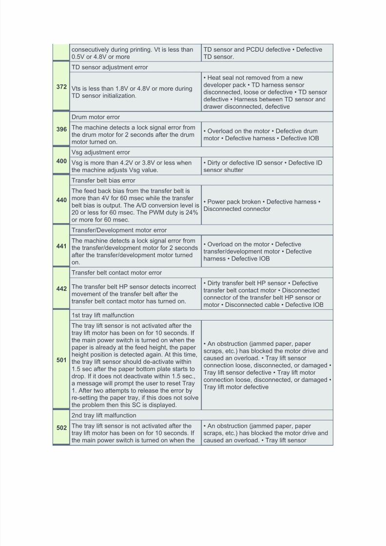
consecutively during printing. Vt is less than0.5V or 4.8V or more
TD sensor and PCDU defective • DefectiveTD sensor.
372
TD sensor adjustment error
Vts is less than 1.8V or 4.8V or more during
TD sensor initialization.
• Heat seal not removed from a newdeveloper pack • TD harness sensordisconnected, loose or defective • TD sensordefective • Harness between TD sensor anddrawer disconnected, defective
396
Drum motor error
The machine detects a lock signal error fromthe drum motor for 2 seconds after the drummotor turned on.
• Overload on the motor • Defective drummotor • Defective harness • Defective IOB
400
Vsg adjustment error
Vsg is more than 4.2V or 3.8V or less whenthe machine adjusts Vsg value.
• Dirty or defective ID sensor • Defective IDsensor shutter
440
Transfer belt bias error
The feed back bias from the transfer belt ismore than 4V for 60 msec while the transferbelt bias is output. The A/D conversion level is20 or less for 60 msec. The PWM duty is 24%or more for 60 msec.
• Power pack broken • Defective harness •Disconnected connector
441
Transfer/Development motor error
The machine detects a lock signal error fromthe transfer/development motor for 2 secondsafter the transfer/development motor turnedon.
• Overload on the motor • Defectivetransfer/development motor • Defectiveharness • Defective IOB
442
Transfer belt contact motor error
The transfer belt HP sensor detects incorrectmovement of the transfer belt after thetransfer belt contact motor has turned on.
• Dirty transfer belt HP sensor • Defectivetransfer belt contact motor • Disconnectedconnector of the transfer belt HP sensor ormotor • Disconnected cable • Defective IOB
501
1st tray lift malfunction
The tray lift sensor is not activated after thetray lift motor has been on for 10 seconds. Ifthe main power switch is turned on when thepaper is already at the feed height, the paperheight position is detected again. At this time,the tray lift sensor should de-activate within1.5 sec after the paper bottom plate starts todrop. If it does not deactivate within 1.5 sec.,
a message will prompt the user to reset Tray1. After two attempts to release the error byre-setting the paper tray, if this does not solvethe problem then this SC is displayed.
• An obstruction (jammed paper, paperscraps, etc.) has blocked the motor drive andcaused an overload. • Tray lift sensorconnection loose, disconnected, or damaged •Tray lift sensor defective • Tray lift motor
connection loose, disconnected, or damaged •Tray lift motor defective
502
2nd tray lift malfunction
The tray lift sensor is not activated after thetray lift motor has been on for 10 seconds. Ifthe main power switch is turned on when the
• An obstruction (jammed paper, paperscraps, etc.) has blocked the motor drive andcaused an overload. • Tray lift sensor
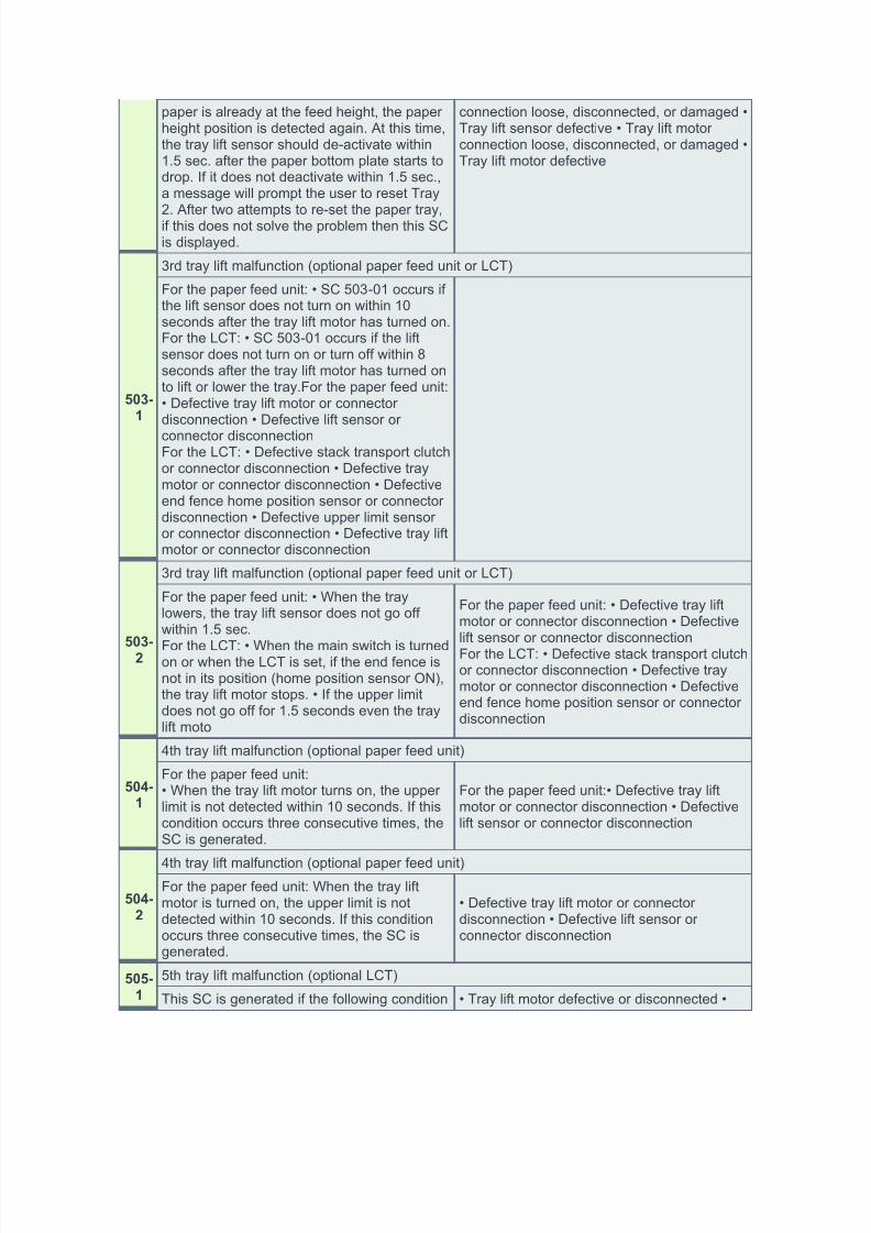
paper is already at the feed height, the paperheight position is detected again. At this time,the tray lift sensor should de-activate within1.5 sec. after the paper bottom plate starts todrop. If it does not deactivate within 1.5 sec.,a message will prompt the user to reset Tray
2. After two attempts to re-set the paper tray,if this does not solve the problem then this SCis displayed.
connection loose, disconnected, or damaged •Tray lift sensor defective • Tray lift motorconnection loose, disconnected, or damaged •Tray lift motor defective
503-
1
3rd tray lift malfunction (optional paper feed unit or LCT)
For the paper feed unit: • SC 503-01 occurs ifthe lift sensor does not turn on within 10seconds after the tray lift motor has turned on.For the LCT: • SC 503-01 occurs if the liftsensor does not turn on or turn off within 8seconds after the tray lift motor has turned onto lift or lower the tray.For the paper feed unit:• Defective tray lift motor or connectordisconnection • Defective lift sensor or
connector disconnectionFor the LCT: • Defective stack transport clutchor connector disconnection • Defective traymotor or connector disconnection • Defectiveend fence home position sensor or connectordisconnection • Defective upper limit sensoror connector disconnection • Defective tray liftmotor or connector disconnection
503-
2
3rd tray lift malfunction (optional paper feed unit or LCT)
For the paper feed unit: • When the traylowers, the tray lift sensor does not go offwithin 1.5 sec.
For the LCT: • When the main switch is turnedon or when the LCT is set, if the end fence isnot in its position (home position sensor ON),the tray lift motor stops. • If the upper limitdoes not go off for 1.5 seconds even the traylift moto
For the paper feed unit: • Defective tray liftmotor or connector disconnection • Defectivelift sensor or connector disconnectionFor the LCT: • Defective stack transport clutchor connector disconnection • Defective traymotor or connector disconnection • Defectiveend fence home position sensor or connectordisconnection
504-
1
4th tray lift malfunction (optional paper feed unit)
For the paper feed unit:• When the tray lift motor turns on, the upperlimit is not detected within 10 seconds. If thiscondition occurs three consecutive times, theSC is generated.
For the paper feed unit:• Defective tray liftmotor or connector disconnection • Defectivelift sensor or connector disconnection
504-
2
4th tray lift malfunction (optional paper feed unit)
For the paper feed unit: When the tray liftmotor is turned on, the upper limit is notdetected within 10 seconds. If this conditionoccurs three consecutive times, the SC isgenerated.
• Defective tray lift motor or connectordisconnection • Defective lift sensor orconnector disconnection
505-
1
5th tray lift malfunction (optional LCT)
This SC is generated if the following condition • Tray lift motor defective or disconnected •
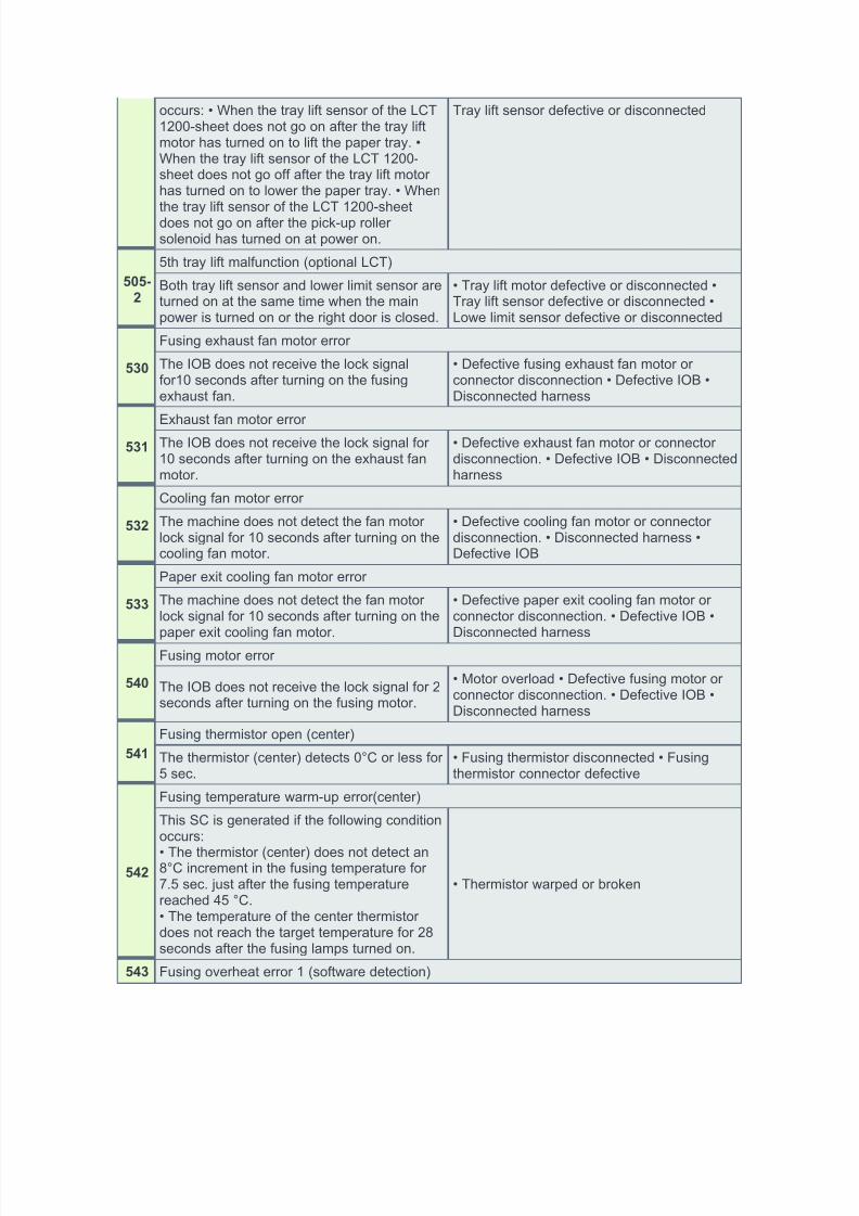
occurs: • When the tray lift sensor of the LCT1200-sheet does not go on after the tray liftmotor has turned on to lift the paper tray. •When the tray lift sensor of the LCT 1200-sheet does not go off after the tray lift motorhas turned on to lower the paper tray. • When
the tray lift sensor of the LCT 1200-sheetdoes not go on after the pick-up rollersolenoid has turned on at power on.
Tray lift sensor defective or disconnected
505-
2
5th tray lift malfunction (optional LCT)
Both tray lift sensor and lower limit sensor areturned on at the same time when the mainpower is turned on or the right door is closed.
• Tray lift motor defective or disconnected •Tray lift sensor defective or disconnected •Lowe limit sensor defective or disconnected
530
Fusing exhaust fan motor error
The IOB does not receive the lock signalfor10 seconds after turning on the fusingexhaust fan.
• Defective fusing exhaust fan motor orconnector disconnection • Defective IOB •Disconnected harness
531
Exhaust fan motor errorThe IOB does not receive the lock signal for10 seconds after turning on the exhaust fanmotor.
• Defective exhaust fan motor or connectordisconnection. • Defective IOB • Disconnectedharness
532
Cooling fan motor error
The machine does not detect the fan motorlock signal for 10 seconds after turning on thecooling fan motor.
• Defective cooling fan motor or connectordisconnection. • Disconnected harness •Defective IOB
533
Paper exit cooling fan motor error
The machine does not detect the fan motorlock signal for 10 seconds after turning on the
paper exit cooling fan motor.
• Defective paper exit cooling fan motor orconnector disconnection. • Defective IOB •
Disconnected harness
540
Fusing motor error
The IOB does not receive the lock signal for 2seconds after turning on the fusing motor.
• Motor overload • Defective fusing motor orconnector disconnection. • Defective IOB •Disconnected harness
541
Fusing thermistor open (center)
The thermistor (center) detects 0°C or less for5 sec.
This SC is generated if the following conditionoccurs:
• The thermistor (center) does not detect an8°C increment in the fusing temperature for7.5 sec. just after the fusing temperaturereached 45 °C.• The temperature of the center thermistordoes not reach the target temperature for 28seconds after the fusing lamps turned on.
When the zero cross signal is 66 or more andit is detected 10 times or more in 11detections, the machine determines that input60 Hz and SC557 occurs.
• Noise (High frequency)
559
Fusing unit jam
The fusing sensor detected a fusing unitpaper late jam three times. The paper waslate and the fusing exit sensor could notdetect the paper three times.
• Remove the paper that is stopped in thefusing unit. • Check that the fusing unit isclean and has no obstacles in the paper feedpath. • If the error persists, replace the fusingunit.
610
Mechanical counter error: BK
This SC is only for NA models. The machinedetects the mechanical counter error whenSP5987-001 is set to "1".
Communication timeout error between IOB and finisher or mailbox
A break (low) signal is received from thefinisher or the mailbox.
• Disconnected cable • Defective IOB •Defective main board in the peripherals
622
Paper feed unit communication error
While the IOB communicates with aperipheral, an SC code is displayed if one offollowing conditions occurs. • The IOBreceives the break signal which is generatedby the peripheral only just after the mainswitch is turned on. • The IOB receives thebreak signal which is generated by URAT.
• Defective main control board of theperipheral • Defective BICU or IOB •Disconnected peripheral
623
2nd Paper Bank communication error
This SC is not issued for this machine. Whena communication error signal between the 1stpaper bank and 2nd paper bank is received.
• Loose connector
630
CSS communication error
A communication error occurred duringcommunication with the CSS.
• Communication line error
632
MF accounting device error 1
The controller sends data to the accountingdevice, but the device does not respond. Thisoccurs three times.
• Loose connection between the controllerand the accounting device
633
MF accounting device error 2
After communication is established, thecontroller receives the brake signal from theaccounting device.
• Loose connection between the controllerand the accounting device
The accounting device sends the controllerthe report that indicates a backup RAM errorhas occurred.
• Defective controller of the MF accountingdevice • Battery error
635
MF accounting device error 4
The accounting device sends the controllerthe report that indicates the battery voltageerror has occurred.
• Defective controller of the MF accountingdevice • Battery error
636
-01
IC Card Error: External authentication module error
This SC is generated if the externalauthentication is enabled and followingcondition occurs: • No external authenticationmodule • SD card error or externalauthentication module broken • No DESSmodule
636
-02
IC Card Error: Version error
The version of the external authenticationmodule is not correct. • Incorrect module version
636
-99
IC Card Error: Management area error
The management number of the externalauthentication module exceeds the maximumlimit.
• Software error
641
BICU communication error
The BICU does not respond to the frametransmitted from the controller.
• Defective controller • Detective BICU
650
-001
Communication error of the remote service modem (Embedded RCG-M): Authentication error
The authentication for the Embedded RCG-Mfails at a dial up connection.
• Incorrect SP settings • Disconnected
telephone line • Disconnected modem boardCheck and set the correct user name(SP5816-156) and password (SP5816-157).
650
-004
Communication error of the remote service modem (Embedded RCG-M): Incorrect modemsetting
Dial up fails due to the incorrect modemsetting.
• Same as -001 Check and set the correct ATcommand (SP5816-160).
650
-005
Communication error of the remote service modem (Embedded RCG-M): Communication lineerror
The supplied voltage is not sufficient due to adefective communication line or defectiveconnection.
• Same as -001 Consult with the user's localtelephone company.
650
-011
Communication error of the remote service modem (Embedded RCG-M): Incorrect networksetting
Both the NIC and Embedded RCG-M areactivated at the same time.
• Same as -001 Disable the NIC with SP5985-1.
650
-012
Communication error of the remote service modem (Embedded RCG-M): Modem board error
The modem board does not work properlyeven though the setting of the modem board
• Same as -001 1. Install the modem board. 2.Check and reset the modem board setting
is installed with a dial up connection. with SP5816. 3. Replace the modem board.
651
-001
Incorrect dial up connection: Program parameter error
An unexpected error occurs when the modem(Embedded RCG-M) tries to call the centerwith a dial up connection.
• Caused by a software bug
651
-002
Incorrect dial up connection: Program execution error
An unexpected error occurs when the modem(Embedded RCG-M) tries to call the centerwith a dial up connection.
• Caused by a software bug
669
EEPROM error
Retry of EEPROM communication fails threetimes after the machine has detected theEEPROM error.
• Caused by noise
670
Engine startup error
The BICU fails to respond with the prescribed
time when the machine is turned on.
• Connections between BICU and controllerboard are loose, disconnected, or damaged 1.
Replace the BICU 2. Replace the controllerboard
671
BICU error
The model code from the BICU is not correctwhen the machine is turned on.
Install the correct BICU for this model.
672
Controller-to-operation panel communication error at startup
• After the machine is powered on, thecommunication between the controller and theoperation panel is not established, orcommunication with controller is interruptedafter a normal startup. • After startup reset ofthe operation panel, the attention code or theattention acknowledge code is not sent fromthe controller within 15 seconds. • After thecontroller issues a command to check thecommunication line with the controller at 30-second intervals, the controller fails torespond twice.
• The controller is not completely shutdownwhen you turn the main switch off. Check thesetting of SP5875-001. If the setting is set to"1 (OFF)", change it to "0 (ON)".
687
Memory address (PER) command error
The BICU does not receive a memoryaddress command from the controller for theprescribed time after the paper has reachedthe registration sensor.
• Harness Disconnection at BICU • Controllerboard loose or broken • Defective BICU •Defective Controller Board
700
Original stopper HP errorWhen the pick-up motor turns on clockwise,the original stopper HP sensor does notdetect the home position of the originalstopper.
• Defective original stopper HP sensor •Defective pick-up motor • Defective DF driveboard
701
Pick-up roller HP error
When the pick-up motor turns oncounterclockwise, the pick-up roller HP
• Defective pick-up roller HP sensor •Defective pick-up motor • Defective DF drive
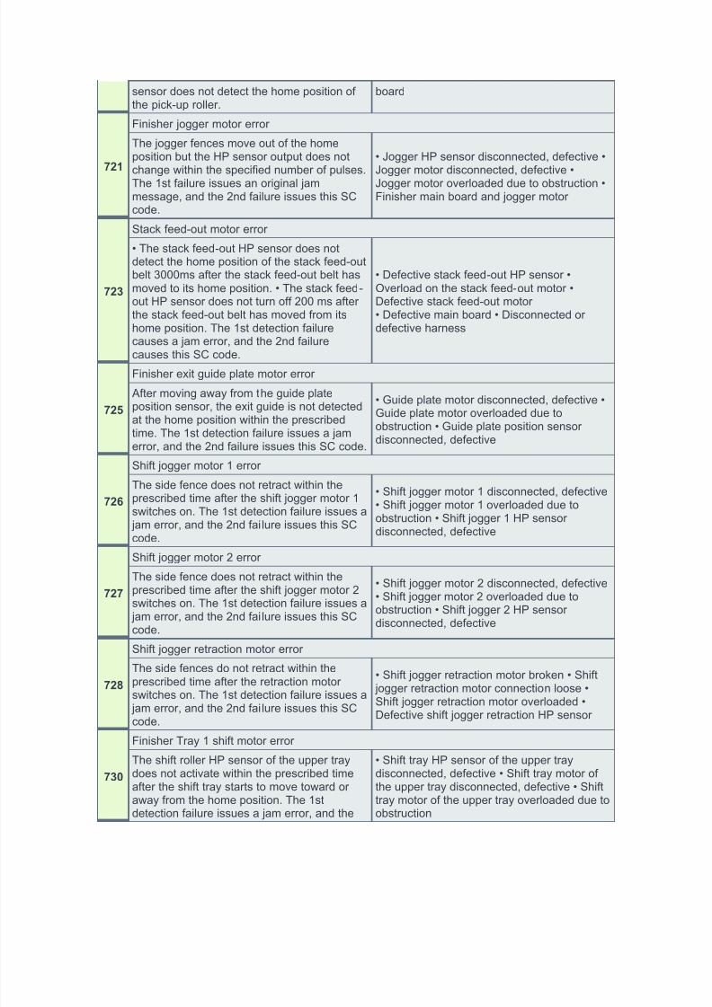
sensor does not detect the home position ofthe pick-up roller.
board
721
Finisher jogger motor error
The jogger fences move out of the homeposition but the HP sensor output does notchange within the specified number of pulses.The 1st failure issues an original jammessage, and the 2nd failure issues this SCcode.
• Jogger HP sensor disconnected, defective •Jogger motor disconnected, defective •Jogger motor overloaded due to obstruction •Finisher main board and jogger motor
723
Stack feed-out motor error
• The stack feed-out HP sensor does notdetect the home position of the stack feed-outbelt 3000ms after the stack feed-out belt hasmoved to its home position. • The stack feed-out HP sensor does not turn off 200 ms afterthe stack feed-out belt has moved from itshome position. The 1st detection failurecauses a jam error, and the 2nd failure
causes this SC code.
• Defective stack feed-out HP sensor •Overload on the stack feed-out motor •Defective stack feed-out motor• Defective main board • Disconnected ordefective harness
725
Finisher exit guide plate motor error
After moving away from the guide plateposition sensor, the exit guide is not detectedat the home position within the prescribedtime. The 1st detection failure issues a jamerror, and the 2nd failure issues this SC code.
• Guide plate motor disconnected, defective •Guide plate motor overloaded due toobstruction • Guide plate position sensordisconnected, defective
726
Shift jogger motor 1 error
The side fence does not retract within theprescribed time after the shift jogger motor 1switches on. The 1st detection failure issues a
jam error, and the 2nd failure issues this SCcode.
• Shift jogger motor 1 disconnected, defective• Shift jogger motor 1 overloaded due toobstruction • Shift jogger 1 HP sensor
disconnected, defective
727
Shift jogger motor 2 error
The side fence does not retract within theprescribed time after the shift jogger motor 2switches on. The 1st detection failure issues a jam error, and the 2nd failure issues this SCcode.
• Shift jogger motor 2 disconnected, defective• Shift jogger motor 2 overloaded due toobstruction • Shift jogger 2 HP sensordisconnected, defective
728
Shift jogger retraction motor error
The side fences do not retract within theprescribed time after the retraction motorswitches on. The 1st detection failure issues a
jam error, and the 2nd failure issues this SCcode.
• Shift jogger retraction motor broken • Shift jogger retraction motor connection loose •
Shift jogger retraction motor overloaded •Defective shift jogger retraction HP sensor
730
Finisher Tray 1 shift motor error
The shift roller HP sensor of the upper traydoes not activate within the prescribed timeafter the shift tray starts to move toward oraway from the home position. The 1stdetection failure issues a jam error, and the
• Shift tray HP sensor of the upper traydisconnected, defective • Shift tray motor ofthe upper tray disconnected, defective • Shifttray motor of the upper tray overloaded due toobstruction
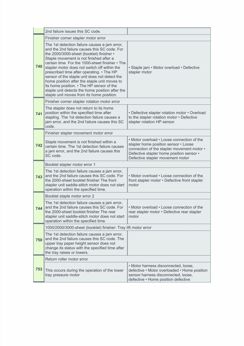
The 1st detection failure causes a jam error,and the 2nd failure causes this SC code. Forthe 2000/3000-sheet (booklet) finisher •Staple movement is not finished after acertain time. For the 1000-sheet finisher • Thestapler motor does not switch off within theprescribed time after operating. • The HPsensor of the staple unit does not detect thehome position after the staple unit moves toits home position. • The HP sensor of thestaple unit detects the home position after thestaple unit moves from its home position.
• Staple jam • Motor overload • Defectivestapler motor
741
Finisher corner stapler rotation motor error
The stapler does not return to its homeposition within the specified time afterstapling. The 1st detection failure causes a
jam error, and the 2nd failure causes this SCcode.
• Defective stapler rotation motor • Overloadto the stapler rotation motor • Defective
stapler rotation HP sensor
742
Finisher stapler movement motor error
Staple movement is not finished within acertain time. The 1st detection failure causesa jam error, and the 2nd failure causes thisSC code.
• Motor overload • Loose connection of thestapler home position sensor • Looseconnection of the stapler movement motor •Defective stapler home position sensor •Defective stapler movement motor
743
Booklet stapler motor error 1
The 1st detection failure causes a jam error,and the 2nd failure causes this SC code. For
the 2000-sheet booklet finisher The frontstapler unit saddle-stitch motor does not startoperation within the specified time.
• Motor overload • Loose connection of the
front stapler motor • Defective front staplermotor
744
Booklet staple motor error 2
The 1st detection failure causes a jam error,and the 2nd failure causes this SC code. Forthe 2000-sheet booklet finisher The rearstapler unit saddle-stitch motor does not startoperation within the specified time.
• Motor overload • Loose connection of therear stapler motor • Defective rear staplermotor
750
1000/2000/3000-sheet (booklet) finisher: Tray lift motor error
The 1st detection failure causes a jam error,and the 2nd failure causes this SC code. The
upper tray paper height sensor does notchange its status with the specified time afterthe tray raises or lowers.
753
Return roller motor error
This occurs during the operation of the lowertray pressure motor
• Motor harness disconnected, loose,defective • Motor overloaded • Home positionsensor harness disconnected, loose,defective • Home position defective
The punch HP sensor is not activated withinthe specified time after the punch motorturned on. The 1st detection failure causes a jam error, and the 2nd failure causes this SCcode.
• Punch HP sensor disconnected, defective •Punch motor disconnected or defective •Punch motor overload due to obstruction
761
Finisher folder plate motor error
The folder plate moves but is not detected atthe home position within the specified time.The 1st detection failure causes a jam error,and the 2nd failure causes this SC code.
• Folder plate HP sensor disconnected,defective • Folder plate motor disconnected,defective • Folder plate motor overloaded dueto obstruction.
763
Punch movement motor error
The punch unit moves but is not detected atthe home position within the specified time.The 1st detection failure causes a jam error,and the 2nd failure causes this SC code.
• Motor harness disconnected, loose,defective • Defective motor
764
Paper position sensor slide motor error
The paper position sensor moves but is notdetected at the home position within thespecified time. The 1st detection failurecauses a jam error, and the 2nd failurecauses this SC code.
• Motor harness disconnected, loose,defective • Defective motor
765
Folding unit bottom fence lift motor
The folding unit bottom fence movement isnot finished within a certain time. The 1stdetection failure causes a jam error, and the2nd failure causes this SC code.
• Motor harness loose, broken • Motor driveobstructed • Motor defective
766
Clamp roller retraction motor error
The clamp roller movement is not finishedwithin a certain time. The 1st detection failurecauses a jam error, and the 2nd failurecauses this SC code.
• Motor harness loose, broken • Motor driveobstructed • Motor defective
767
Stack junction gate motor error
The stack junction gate motor moves but thestack junction gate is not detected at itsposition within a specific time. The 1stdetection failure causes a jam error, and the2nd failure causes this SC code.
• Motor broken • Motor connection loose •Motor overloaded
770
Shift motor error
The shift motor HP sensor does not detectany change for 1.86 seconds after the shiftmotor has turned on at power on or during itsoperation.
• Defective shift motor • Defective shift motorHP sensor
791
Bridge unit error
The machine recognizes the finisher, but doesnot recognize the bridge unit.
Energy saver sub-system detects an error. • Defective controller board
817
Monitor Error
This is a file detection and electronic filesignature check error when the boot loaderattempts to read the self-diagnostic module,system kernel, or root system files from theOS Flash ROM, or the items on the SD cardin the controller slot are false or corrupted.
• OS Flash ROM data defective; change thecontroller firmware • SD card data defective;use another SD card
819
Fatal kernel error
Due to a control error, a RAM overflowoccurred during system processing. One ofthe following messages was displayed on theoperation panel.
• System program defective • Controller boarddefective• Optional board defective • Replace controllerfirmware
820
Self-diagnostics error: CPU [XXXX]: Detailed error code
CPU error• System firmware problem • Defectivecontroller
821 Self-diagnostics error: ASIC
822
Self-diagnostic error: HDD
• HDD device busy for over 31 s. • After adiagnostic command is set for the HDD, butthe device remains busy for over 6 s.
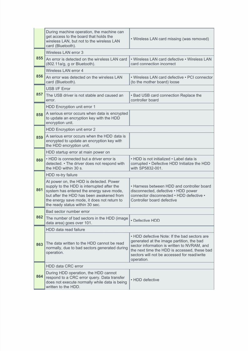
During machine operation, the machine canget access to the board that holds thewireless LAN, but not to the wireless LANcard (Bluetooth).
• Wireless LAN card missing (was removed)
855
Wireless LAN error 3
An error is detected on the wireless LAN card(802.11a/g, g or Bluetooth).
• Wireless LAN card defective • Wireless LANcard connection incorrect
856
Wireless LAN error 4
An error was detected on the wireless LANcard (Bluetooth).
• Wireless LAN card defective • PCI connector(to the mother board) loose
857
USB I/F Error
The USB driver is not stable and caused anerror.
• Bad USB card connection Replace thecontroller board
858
HDD Encryption unit error 1
A serious error occurs when data is encryptedto update an encryption key with the HDD
encryption unit.
859
HDD Encryption unit error 2
A serious error occurs when the HDD data isencrypted to update an encryption key withthe HDD encryption unit.
860
HDD startup error at main power on
• HDD is connected but a driver error isdetected. • The driver does not respond withthe HDD within 30 s.
• HDD is not initialized • Label data iscorrupted • Defective HDD Initialize the HDDwith SP5832-001.
861
HDD re-try failure
At power on, the HDD is detected. Powersupply to the HDD is interrupted after thesystem has entered the energy save mode,but after the HDD has been awakened fromthe energy save mode, it does not return tothe ready status within 30 sec.
• Harness between HDD and controller boarddisconnected, defective • HDD powerconnector disconnected • HDD defective •Controller board defective
862
Bad sector number error
The number of bad sectors in the HDD (imagedata area) goes over 101.
• Defective HDD
863
HDD data read failure
The data written to the HDD cannot be readnormally, due to bad sectors generated duringoperation.
• HDD defective Note: If the bad sectors aregenerated at the image partition, the bad
sector information is written to NVRAM, andthe next time the HDD is accessed, these badsectors will not be accessed for read/writeoperation.
864
HDD data CRC error
During HDD operation, the HDD cannotrespond to a CRC error query. Data transferdoes not execute normally while data is beingwritten to the HDD.
HDD responded to an error during operationfor a condition other than those for SC863,864.
• HDD defective.
866
SD card error 1: Confirmation
The machine detects an electronic licenseerror in the application on the SD card in thecontroller slot immediately after the machineis turned on. The program on the SD cardcontains electronic confirmation license data.If the program does not contain this licensedata, or if the result of the check shows thatthe license data in the program on the SDcard is incorrect, then the checked programcannot execute and this SC code is displayed.
• Program missing from the SD card •Download the correct program for themachine to the SD card
867
SD card error 2: SD card removed
The SD card in the slot is removed while the
machine is on.
Insert the SD card, then turn the machine off
and on.
868
SD card error 3: SC card access
An error occurs while an SD card is used.
• SD card not inserted correctly • SD carddefective • Controller board defective Note: Ifyou want to try to reformat the SC card, useSD Formatter Ver 1.1.
870
Address book data error
The address book data cannot be read fromthe HDD, SD card or flash ROM on thecontroller where it is stored, or the data read
from the media is defective.
• Software defective: Turn the machine off/on.If this is not the solution for the problem, thenreplace the controller firmware. • HDDdefective. • Do SP5846-046 (Initialize AllSetting & Addr Book) to reset all address
book data. • Reset the user information withSP5832-006 (HDD Formatting – UserInformation). • Replace the HDDs.
872
HDD mail receive data error
• The machine detects that the HDD is notoperating correctly at power on. • Themachine detects that the HDD is not operatingcorrectly (can neither read nor write) whileprocessing incoming email.
• HDD defective • The machine is turned offwhile the HDD is being accessed. DoSP5832-007 to format the mail RX data onthe HDD.
873
HDD mail send data error
An error is detected on the HDD immediately
after the machine has been turned on, orpower has been turned off while the machinehas used the HDD.
1. Do SP5832-008 (Format HDD – Mail TX
Data) to initialize the HDD. 2. Replace theHDD
874
Delete All error 1: HDD
A data error is detected for the HDD/NVRAMafter the Delete All option has been used.Note: The source of this error is theDataOverwriteSecurity Unit (D362) runningfrom an SD card.
1. Turn the main switch off/on and try theoperation again. 2. Install theDataOverwriteSecurity Unit again. For more,see “Installation”. 3. HDD defective
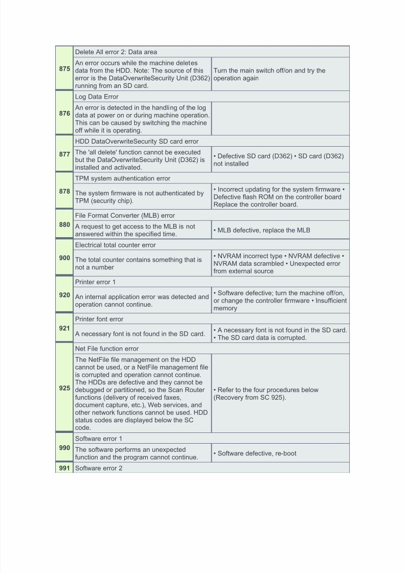
An error occurs while the machine deletesdata from the HDD. Note: The source of thiserror is the DataOverwriteSecurity Unit (D362)running from an SD card.
Turn the main switch off/on and try theoperation again
876
Log Data Error
An error is detected in the handling of the logdata at power on or during machine operation.This can be caused by switching the machineoff while it is operating.
877
HDD DataOverwriteSecurity SD card error
The 'all delete' function cannot be executedbut the DataOverwriteSecurity Unit (D362) isinstalled and activated.
• Incorrect updating for the system firmware •Defective flash ROM on the controller boardReplace the controller board.
880
File Format Converter (MLB) error
A request to get access to the MLB is notanswered within the specified time.
• MLB defective, replace the MLB
900
Electrical total counter error
The total counter contains something that isnot a number
• NVRAM incorrect type • NVRAM defective •NVRAM data scrambled • Unexpected errorfrom external source
920
Printer error 1
An internal application error was detected andoperation cannot continue.
• Software defective; turn the machine off/on,
or change the controller firmware • Insufficientmemory
921
Printer font error
A necessary font is not found in the SD card.• A necessary font is not found in the SD card.• The SD card data is corrupted.
925
Net File function error
The NetFile file management on the HDDcannot be used, or a NetFile management fileis corrupted and operation cannot continue.The HDDs are defective and they cannot bedebugged or partitioned, so the Scan Routerfunctions (delivery of received faxes,document capture, etc.), Web services, andother network functions cannot be used. HDDstatus codes are displayed below the SCcode.
• Refer to the four procedures below(Recovery from SC 925).
990
Software error 1
The software performs an unexpectedfunction and the program cannot continue.
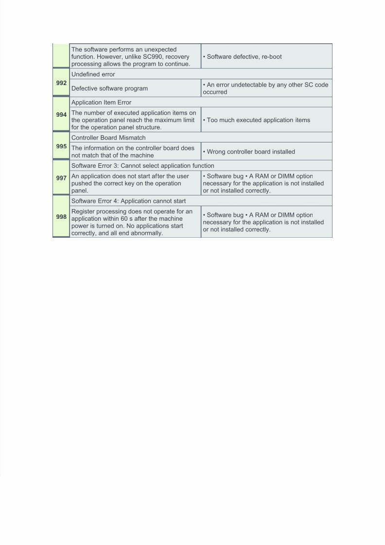
The software performs an unexpectedfunction. However, unlike SC990, recoveryprocessing allows the program to continue.
• Software defective, re-boot
992
Undefined error
Defective software program• An error undetectable by any other SC codeoccurred
994
Application Item Error
The number of executed application items onthe operation panel reach the maximum limitfor the operation panel structure.
• Too much executed application items
995
Controller Board Mismatch
The information on the controller board doesnot match that of the machine
• Wrong controller board installed
997
Software Error 3: Cannot select application function
An application does not start after the userpushed the correct key on the operation
panel.
• Software bug • A RAM or DIMM optionnecessary for the application is not installed
or not installed correctly.
998
Software Error 4: Application cannot start
Register processing does not operate for anapplication within 60 s after the machinepower is turned on. No applications startcorrectly, and all end abnormally.
• Software bug • A RAM or DIMM optionnecessary for the application is not installedor not installed correctly.