STO-EN-SET-216 2 - 1 Cognitive Tracking, Resource Management and Waveforms for Cognitive Radars Krzysztof S. Kulpa Institute of Electronic Systems, Warsaw University of Technology Nowowiejska 15/19, 00-665 Warszawa POLAND [email protected]ABSTRACT The paper presents the idea of cognitive radar resource management for modern radars together with remarks on cognitive tracking, and an overview of radar waveforms and their selection in order to perform the desired radar tasks. The cognition is based on the observation and understanding of the change of environment in which the radar works and the adaptation of the radar’s behaviour to the changing conditions based on the knowledge learned through the observation of the environment and the results of previous behavioural changes. Cognition can have an important impact on safety both in civil and military environments, so the new knowledge has to be distributed among the radar’s sensors using a net-centric approach and must also be carefully supervised to prevent the wrong decision being made during the cognition/learning process. It is important to note that a wrong decision can have a mortal effect on the radar and/or the controlled vehicles, so information on the effect of a wrong decision should be distributed immediately among the sensors to prevent the multiplication of erroneous situations and behaviours. 1.0 INTRODUCTION Over the last decade the word “cognitive” has started to become more and more common. We have “cognitive radios”, “cognitive systems” and now “cognitive radars”. But what exactly does it mean? In one of the most widely used sources of knowledge today, Wikipedia, the following definition of “cognition” can be found: It can be seen that cognition is related to gathering new knowledge and changing behaviour based on both old and new knowledge. It is related to making the use of the ability to learn through observation and to change one’s own behaviour in order to adapt to changes of the environment. The definition presented above is very general and addressed more towards people than the machines or systems constructed by man. The cognitive radar is a man-made product and the idea of cognitive radar is in fact the evolution of two ideas – cognitive radio and cognitive network. Again Wikipedia can be referred to regarding these two subjects. “Cognition is the set of all mental abilities and processes related to knowledge: attention, memory and working memory, judgment and evaluation, reasoning and “computation“, problem solving and decision making, comprehension and production of language, etc. Human cognition is conscious and unconscious, concrete or abstract, as well as intuitive (like knowledge of a language) and conceptual (like a model of a language). Cognitive processes use existing knowledge and generate new knowledge.”
Transcript
STO-EN-SET-216 2 - 1
Cognitive Tracking, Resource Management and Waveforms for Cognitive Radars
Krzysztof S. Kulpa Institute of Electronic Systems, Warsaw University of Technology
ABSTRACT The paper presents the idea of cognitive radar resource management for modern radars together with remarks on cognitive tracking, and an overview of radar waveforms and their selection in order to perform the desired radar tasks. The cognition is based on the observation and understanding of the change of environment in which the radar works and the adaptation of the radar’s behaviour to the changing conditions based on the knowledge learned through the observation of the environment and the results of previous behavioural changes.
Cognition can have an important impact on safety both in civil and military environments, so the new knowledge has to be distributed among the radar’s sensors using a net-centric approach and must also be carefully supervised to prevent the wrong decision being made during the cognition/learning process. It is important to note that a wrong decision can have a mortal effect on the radar and/or the controlled vehicles, so information on the effect of a wrong decision should be distributed immediately among the sensors to prevent the multiplication of erroneous situations and behaviours.
1.0 INTRODUCTION Over the last decade the word “cognitive” has started to become more and more common. We have “cognitive radios”, “cognitive systems” and now “cognitive radars”. But what exactly does it mean?
In one of the most widely used sources of knowledge today, Wikipedia, the following definition of “cognition” can be found:
It can be seen that cognition is related to gathering new knowledge and changing behaviour based on both old and new knowledge. It is related to making the use of the ability to learn through observation and to change one’s own behaviour in order to adapt to changes of the environment.
The definition presented above is very general and addressed more towards people than the machines or systems constructed by man.
The cognitive radar is a man-made product and the idea of cognitive radar is in fact the evolution of two ideas – cognitive radio and cognitive network. Again Wikipedia can be referred to regarding these two subjects.
“Cognition is the set of all mental abilities and processes related to knowledge: attention, memory and working memory, judgment and evaluation, reasoning and “computation“, problem solving and decision making, comprehension and production of language, etc. Human cognition is conscious and unconscious, concrete or abstract, as well as intuitive (like knowledge of a language) and conceptual (like a model of a language). Cognitive processes use existing knowledge and generate new knowledge.”
Cognitive Tracking, Resource Management and Waveforms for Cognitive Radars
2 - 2 STO-EN-SET-216
The Wikipedia definition of “cognitive radio” is as follows:
and the Wikipedia definition of “cognitive network” is:
The question is how to apply the idea of cognition to the radar.
This problem is not new; for more than a decade scientists have been working on how to solve it. Several conference and journal papers have been written on this subject, and on the market several books can be found [1-3,49].
But let us start our consideration from a fundamental question: for what purpose are radars designed and installed? There are several answers to this question, as there are several classes of radars and several application fields.
In the past the most important civil application of the radar was for air traffic control (ATC). Primary radars together with secondary radars have been installed all over the world to provide wide area coverage and perform the function of target tracking. The main goal was to increase aviation safety and provide collision warnings. This ability was very limited when solely using primary radars, so at the present moment air traffic control is based mainly on secondary radars, where airplanes actively respond to a secondary radar request by providing information of their position, speed, altitude and other parameters. Such systems are very reliable and precise, but do not provide collision warnings with objects not equipped with transponders or objects in which transponders are malfunctioning or simply switched off.
Thus to ensure air safety, a primary radar has to be used. The main challenge for a primary ATC radar is to track all aerial targets in the surveillance area in the presence of clutter and surface traffic. ATC radars have
“In communication networks, cognitive network (CN) is a new type of data network that makes use of cutting edge technology from several research areas (i.e. machine learning, knowledge representation, computer network, network management) to solve some problems current networks are faced with. Cognitive network is different from cognitive radio (CR) as it covers all the layers of the OSI model (not only layers 1 and 2 as with CR (Mitola 2000)).” ……. “Thomas et al. (Thomas 2005) define the CN as a network with a cognitive process that can perceive current network conditions, plan, decide, act on those conditions, learn from the consequences of its actions, all while following end-to-end goals. This loop, the cognition loop, senses the environment, plans actions according to input from sensors and network policies, decides which scenario fits best its end-to-end purpose using a reasoning engine, and finally acts on the chosen scenario as discussed in the previous section. The system learns from the past (situations, plans, decisions, actions) and uses this knowledge to improve the decisions in the future.” Wikipedia, https://en.wikipedia.org/wiki/Cognitive_network, 05.08.2015
“A cognitive radio is an intelligent radio that can be programmed and configured dynamically. Its transceiver is designed to use the best wireless channels in its vicinity. Such a radio automatically detects available channels in wireless spectrum, then accordingly changes its transmission or reception parameters to allow more concurrent wireless communications in a given spectrum band at one location. This process is a form of dynamic spectrum management.” Wikipedia, https://en.wikipedia.org/wiki/Cognitive_radio, 05.08.2015
Cognitive Tracking, Resource Management and Waveforms for Cognitive Radars
STO-EN-SET-216 2 - 3
to adapt to the changes of clutter and traffic, and they have time to “learn”, but the learning process must be controlled; the consequences of a “learning error” could be an air collision, which must of course be avoided with a very high rate of probability. So in this application there is no room for learning from one’s own errors – at least regarding errors that may lead to the risk of an air collision.
A second important area of radar application involves the military. Military radars are used for air surveillance (ground, airborne and speceborne radars), defence (aircraft radars), and weapons control (airborne, ground). These radars have to operate in very demanding environments, full of electromagnetic transmissions and in the presence of countermeasures. Thus they have to be resistant not only to natural clutter, but also man-made interferences and jamming. The “cognition” in this class of radar is very important as they have to “learn” how to work in different situations, but the time for learning is much shorter, and the consequences of a wrong decision can be fatal.
Currently a third area of radar application is growing rapidly – automotive radars. Higher classes of cars are now equipped with radars which control road safety, assist the drivers, limit blind spot problems, provide autonomous cruise control by adapting to the speed of the car in front, and provide action if there is danger of a foreseeable collision. Intensive research is being carried out to build autonomous vehicles equipped with sensors that can fully control the car’s behaviour. Automotive radars are among those sensors and it is believed that the safety of autonomous vehicles will be much higher than those driven by people. In such cases, the ability to learn and to adapt to unknown situations is crucial; there is a very small margin of error, as each error could result in an accident.
As a result, cognition will be a very important feature in future radars [1, 2, 3], but it must be carefully introduced and fully controlled as there is almost no room for mistakes, and each “learning error” has to be carefully analysed and removed.
In society there are mechanisms for the removal of such “learning errors”. Such mechanisms are based on “networking” and “communication”. In each case when an “error” is detected (at least for cases leading to serious safety violations) a report is generated and widely distributed to make learning easier, and this allows people to learn from others’ experience and “errors”.
The same mechanism must also be introduced to radar sensors and systems. All “cognition” and “learning” have to be performed “globally” and sensors have to exchange their “knowledge” and “experience” to minimize the amount of situations where the sensor has to “learn” based on its own experience and own “errors”. As a result all “cognitive” radar sensors have to work in a net-centric environment and exchange their knowledge, experience and “error reports” to minimize the “error decision rate”.
Another important issue is the control of the “learning process”. In society people construct hierarchical control structures to minimize the chance of a situation where errors occur in the definition of “goals” and the interpretation of “errors”.
It is easy to imagine that an improper approach to setting goals can lead to the situation whereby the “elimination” of traffic could be the best solution. Thus the system could evolve in such a manner that the best solution would be the reduction or full elimination of traffic instead of traffic management. Such situations can also be observed now in society, even for traffic management, which is why it is much easier and cheaper to limit traffic than to improve or update traffic infrastructures. All over the world attempts have been made to remove traffic from city centres by the introduction of traffic free zones or by introducing disincentives such as high tolls for entering the city.
It is also possible to conceive of some “dark scenarios” where a computer net-centric system could limit the “accident probability” in the future and cause collisions. Thus it is hard to envision “cognitive systems” being used without supervision, as without it could lead to unexpected and dangerous behaviour.
Cognitive Tracking, Resource Management and Waveforms for Cognitive Radars
2 - 4 STO-EN-SET-216
2.0 RADAR RESOURCE MANAGEMENT
The history of radar was initiated in the 20th century. There are several “fathers” of the radar, one of whom was a German engineer by the name of Christian Hulsmeyer. He started his work after observing a ship’s collision on the river Rhine. His device, named the “telemobiloscope” and patented in the year 1903, was the predecessor of the modern radar, but it should not be considered a true radar system as radar refers to “RAdio Detection And Ranging” and the “telemobiloscope” only had detection and angular measurement capability. Further development of radars took place before WWII and at that time the radar was able to measure azimuth and distance, and some more advanced systems also measured elevation.
The Home Chain was the first operational British radar which used dipole Tx and Rx antennas. This made it possible to illuminate instantaneously the entire surveillance space, and the only dimensions of freedom for this radar were in the selection of the carrier frequency, pulse repetition frequency and pulse width (and pulse bandwidth equal to the reciprocal of the pulse width).
To decrease the required emitted power directional Tx/Rx antennas were introduced, and then another parameter was added to the list of controlled/managed parameters: antenna rotation speed (for surveillance radar) or time on target.
The introduction of coded signals added completely new capabilities: the independent selection of pulse width and pulse bandwidth, and later the codes. As different waveforms could be selected it allowed for a completely new area of freedom: waveform diversity.
The development of the phase scanned radar also created another area of freedom: the selection of illumination strategy, illumination time and revisit time. Thus an e-scanned radar needs real resource management, as energy and time are key radar resources.
The first e-scanned radars ware equipped with a single transmitter and sigma-delta receivers (four receiving channels). Further development led to the distribution of the transmitter across the radar antenna aperture and the construction of e-scanned radar antennas from small Tx/Rx modules. This approach led to the multichannel receiver being able to perform space-time processing. Adding a separate signal synthesizer to each Tx/Rx module or to the group of modules introduced the MIMO radar concept and added additional dimensions to radar management [4].
As the single radar sensor has limited capability, limited coverage area and is susceptible to shadowing, fading and intentional jamming, much better results can be obtained where radars are integrated into the sensor net. All netted sensors can exchange data at different levels (e.g. track, plot, row data, commands, reports, observation, etc.) and thus by using a central or distributed data fusion mechanism, increase the quality of provided services (e.g. higher probability of detection, higher update rate, faster track initiation, lower probability of track loss etc.).
The net-centric approach adds another dimension of freedom and other requirements for radar management. In a net-centric environment it is possible to manage radar distribution (sensor position) and manage the network traffic to obtain a better quality of services.
2.1 Goals There are several goals to be achieved in radar management, and more generally in radar operation.
The first, most common goal is to track targets with a high degree of accuracy. It is possible to define different classes of targets; radars can track surface targets (vehicles, pedestrians), sea targets (ships, people in water, oil spills), airborne targets (planes, airliners, fighters, UAVs, drones) and space targets (satellites).
Cognitive Tracking, Resource Management and Waveforms for Cognitive Radars
STO-EN-SET-216 2 - 5
In the case of limited radar resources, which is common in almost all cases, there exists a limitation of tracking performances so the resource assignment strategy depends on the target class. More resources should be assigned to the targets of interest (being of high priority, dangerous for the system, on colliding tracks etc.) than to tracks that are of lower priority/interest. The resource management should be adaptive and change appropriately to external conditions such as external requirements, clutter conditions, jamming conditions and learned knowledge.
The second common goal is identification. In civil aviation identification of a target is performed by secondary radars requesting the target’s response. The airplane transponder responds by providing identification codes, as well as more detailed data. For the military radars interrogate the targets by IFF devices and obtain Friend of Foe coded responses, which are then used in order to recognise the difference between their own assets and others, including enemy planes.
In both cases (civil and military) a lack of an answer means that no knowledge of the target is obtained. It is possible to assume that target is not “friendly”, but beyond that there is no knowledge about the target. To obtain more detailed knowledge a non-cooperative target recognition/identification (NCTR) procedure has to be initiated. To perform such identification more radar resources have to be assigned to the target.
Identification information can be retrieved using several radar technologies:
a) Range Profiling
Range profiling is usually performed by applying a wide-bandwidth illumination waveform with spatial (range) resolution in the range of 0.01 to 0.1 of the length of the target. For air targets the required range resolution varies from 0.15 to 1.5 m (bandwidth 100 MHz to 1 GHz), and for sea targets 0.3 to 6 m (bandwidth 50 to 500 MHz). As the effective cross-sections of target details are usually 10-100 times smaller (in an effective cross-section) than the target, then the energy resources assigned in the range profiling mode have to be 10-100 times higher than in the detection mode. As the target is already detected, it is possible to calculate precisely the required energy resources and assign pre-calculated resources. The cognitive process can be used to adjust those values and provide some identification measures based on the observed track.
The time resource is related mostly to the energy resource, while just a single sounding can provide us with range profile data.
b) ISAR Imaging
Range profiling only provides single-dimensional information, which is dependent on the aspect ratio of the target. More information can be achieved using ISAR imaging. ISAR imaging is based on the Doppler processing of echo data assuming that different elements of the target generate different Doppler histories, which can be separated from others and be used to produce clear 2-D or even 3D target images. Usually one or two dimensions of the image (in the cross-range dimension) are generated thanks to the Doppler effect related to target motion, while in the range direction it is necessary to obtain resolution using a wide band of the sounding pulse, similarly to the previous case.
The ability of ISAR imaging depends significantly on the behaviour of the targets and their trajectory. To create a good ISAR image a target has to change its aspect ratio. The best possible imaging is obtained while the target is rotating. The spatial resolution in such a case is dependent on the change of the aspect angle during the observation time. Both air and surface targets usually do not rotate, and a fast change of aspect angle can be observed only during a target’s manoeuvring. A linear target’s motion can also provide a slight aspect angle change if the motion vector is not parallel to the line of sight. The spatial cross-range resolution depends on the change of the aspect angle, so the spatial resolution depends on the product of the aspect angle change speed and observation time.
Cognitive Tracking, Resource Management and Waveforms for Cognitive Radars
2 - 6 STO-EN-SET-216
To obtain a good ISAR image significant time and energy resources have to be assigned. The key element is the proper selection of the observation time instance and observation duration. This selection can also be improved by cognitive sensing, while in a certain radar location it is possible to learn typical object behaviour and thus select the optimal moment for prolonged observation. Cognition will also help to set the priority of identification.
c) Micro-Doppler Analyses
The idea of micro-Doppler analyses is to detect the Doppler components of the target echo which are specific to specific classes of targets, or even to an individual one among a single class.
In almost all targets the internal periodic motion of target components exists. This motion produces vibrations which propagate to the fuselage, and then modulate the echo signal with a vibration frequency. As the amplitude of the fuselage vibration is very low, the sensitivity of the micro-Doppler sensing is also low and sufficient energy resources have to be assigned to bolster it. In addition, the observation time has to be sufficient to ensure the adequate resolution of spectral analyses. The second effect exploited in the micro-Doppler analyses is the rotation of the external elements of the targets visible to the radar such as rotations of propellers, helicopter rotors blades, wheels, radiator fans and so on. The radar cognition can be used for the proper selection of the illumination intervals based on the gathered knowledge of different target classes and the best position of the targets which would enable the maximum sensitivity of the micro-Doppler analyses and the highest possible chance for the visibility of vibrating or rotating elements.
The third common goal is to coexist with other radars and communication devices in a dense electromagnetic environment. Cognition is one of the most important features of the modern radar that enables undisturbed operation in such a difficult environment. To manage a radar in such an environment it is necessary to sense the occupation of the spectrum and the use of different waveforms. As a result of gathered knowledge the radar should generate sensing signals on the least used frequency. Additional separation from interfering signals can be achieved by proper waveform selection and proper sounding timing. As all players can also adapt to the utilization of spectral and waveform resources, the radar cognition mechanism should also take into account the behaviour of other players.
The fourth common goal is to provide proper detection when an opposing force applies countermeasures. Obtaining proper radar detection in a jammed environment is a great challenge and the radar management procedure has to be smarter than the jammer management procedure. In a jammed environment several radar parameters have to be managed. The most important is the appropriate choice of sounding waveform. High orthogonality between the sounding waveform and jamming signal will result in the low efficiency of jammers and is one of the goals of radar management. Usually radar detection is based on a batch of pulses rather than single one, but the selection of a waveform can be performed for each pulse instead of selecting the same waveform for the whole batch. In addition it is possible to select the time instance for the emission of each pulse. This parameter provides an additional dimension of freedom to the ECCM management and thus can improve a radar’s immunity to jamming. The cognition can help a great deal in radar protection. It can be used for understanding the behaviour of jammers and predict future jamming behaviour.
2.2 Mechanically Scanned Radar Management Radar management in a classical, mechanically scanned radar can be only the simplest on , but a big number of such radars still exist and have to be operational on modern battlefields populated by many other radars, communication devices and jammers.
Although the concept is more than 50 years old, such radars can still be used effectively and modern cognition can be applied. They have mechanical, sequential scanning, so a radar engineer does not have the full freedom to choose the direction of sensing, but other sensing parameters can be freely chosen.
Cognitive Tracking, Resource Management and Waveforms for Cognitive Radars
STO-EN-SET-216 2 - 7
Those parameters are:
a) Rotation speed of antenna. This parameter is within 1-60 RPM (rotations per minute) and can usually be changed during radar operation. Depending on the weight of the antenna, the rotation speed can be changed within a few rotations (for heavy antennas) or during a single rotation. The ability to change the rotational speed from rotation to rotation gives the ability of rotational diversity to the radar, and the ability to change rotational speed during rotation gives the ability to manage the illumination time for different targets. The long illumination time can be used for extending the detection range, detection probability (especially for low RCS targets), to increase the probability of detection in a jammed environment (due to longer duel time and higher energy assignment) and increase plot position estimation accuracy. It can also be used for extending illumination for performing ISAR imaging or micro-Doppler analyses (or both).
b) Pulse energy. Most classical radars do not have the possibility to change the transmitting peak power, so energy management is provided by changing the pulse duration and pulse repetition interval. The limitation comes from the limitation of mean power. Thus in its steady state the pulse width to pulse repetition interval is constant and equal to the duty factor of the transmitter (peak to mean power ratio). Depending on the transmitter’s construction and its heat time constant it is possible to increase the transmitter duty factor for one or several pulses, and then it will be necessary to cool down the transmitter using shorter pulses.
c) Pulse repetition interval. The classical MTD radar requires a batch of these same pulses transmitted with a constant pulse interval. Such illumination is optimal from a single target in thermal noise detection. In the case of clutter it is necessary to tune the pulse repetition frequency to avoid “blind” velocities, while most of the radar works with ambiguity velocity measurement (in low or medium PRF modes). The selection of the PRF in consecutive batches is the subject of radar management. Additionally the track-while-scan can be improved by tuning the PRF according to the predicted radial velocity of the targets of interest. The constant pulse repetition within the batch is not an optimal selection in the case of active synchronous jamming. In such a case the introduction of time staggering provides much better results and can be the subject of cognitive radar management.
d) Carrier frequency. The carrier frequency is a basic resource of the radar that has to be managed. The radar has to sense the allocated spectrum and select the free or the least occupied frequency. The spectrum sensing should be fast enough to provide the best frequency selection in a dynamically changing environment in the presence of interference and jamming. Cognitive radar management is crucial for selecting the frequency selection algorithm especially in the case of jamming, and the intelligence and speed of the applied mechanism should be greater than the one applied in the jammer.
e) Waveform diversity. The waveform selection is the largest area of freedom in the classic radar resource management. In classical radars the most common waveforms are unmodulated pulses and linear frequency modulation (LFM). For long range radars modulated pulses are commonly used to limit the maximum transmitted power below the MW level. Using LFM pulses with a given bandwidth and given pulse duration, only two possibilities exist: up and down chirp. The linear chirp is close to the optimal sounding signal, and is very robust in dealing with the Doppler shift of the echo, so radar processing using this signal is relatively simple. Such a waveform selection is usually sufficient in normal radar operation, but in the case of advanced jamming more waveforms are needed. Thus more advanced waveforms with poly-phase modulation are required. The cognitive strategy for waveform selection from a predefined bank or on-line waveform design will increase a radar’s immunity to advanced jamming. A deeper discussion on the waveforms for cognitive radars is presented in Section 4.
Cognitive Tracking, Resource Management and Waveforms for Cognitive Radars
2 - 8 STO-EN-SET-216
The cognitive radar management in the case of mechanically scanned radars can be used to achieve several goals:
a) Improved radar coverage, especially in selected directions, when the radar works in the net-centric environment and has a responsibility zone
b) Improved quality of tracking, especially selected targets of interest
c) Provide the recognition and identification of tracked targets
d) Increase the immunity for interferences and jamming
2.3 Electronically Scanned Radar Management Modern electronically scanned radars allow for more flexible radar operations and add additional dimensions of freedom to radar management. The development of phase arrays for electronically scanned radars originated in WWII, but fully operational passive electronically scanned area radars date from the middle of the 1970s. Radars such as Patriot, SPY-1 and B1-B were equipped with a central transmitter and passive phase shifters. As a result it was possible to instantaneously direct the radar beam to a required direction. The scanning angle for a single radar phase was limited to c.a. 90 degrees, so 4 radar phase arrays should be required to provide full radar coverage.
In the 1990s the active electronically scanned array was introduced, and such radars as F/A-22, JSF, MP-RTIP, THAAD, SBX and SPY-3 were constructed. These radars were equipped with a number of transmit/receive modules. Each module of this type of radar can be individually controlled so apart from the possibility of forming a single Tx/Rx beam, it is possible to split the aperture and form several instantaneous beams. The number of possible beams is limited by the number of receiving channels.
The recent development of microwave integrated circuits, direct signal synthesizers (DDS), integrated transceivers and fast ADCs has led to the concept of the integration of digital signal synthesizers and digital receivers into a single Tx/Rx module. At the present stage of development it is possible to make such an integration from modules in the UHF band. For higher bands this solution is still too expensive both in financial and energetic aspects, but it is now possible to use separate signal synthesis and digitizers for small sub-apertures constructed using Tx/Rx modules. This is the future direction for active electronically scanned radars.
The management of a passively or actively scanned area is much more complicated due to the additional dimension of freedom. In such radars it is possible to manage the following parameters:
a) Surveillance time. This parameter is similar to the antenna scan time (or antenna rotation speed) in a conventional radar. It is the time needed for searching all surveillance volume to detect new targets. In a classical radar, for new target acquisition 3-5 scans are required. In an e-scanned radar 1-2 scans are sufficient, so the surveillance time can be approximately twice as long as the antenna revolution time in a conventional radar. In a classical mechanically scanned radar the surveillance area usually forms a circle with a radius equal to the radar detection range. For an e-scan radar it is possible to form a surveillance region in almost any shape by applying proper resource management. Additionally, in the event of more important tasks appearing this parameter can be extended in order to assign more radar resources to the higher priority tasks.
b) Track update time. In the mechanically scanned radar the track update rate is equal to the time of the antenna’s full rotation. In an e-scan radar it is possible to direct the beam towards the track with an arbitral chosen refresh time. The refresh time can be selected independently for all tracked targets based on assigned priority or target behaviour. The refresh time can then be selected from several milliseconds to several seconds, or the track may be refreshed only during surveillance scans. The resources needed for a track update depend on the required quality of tracking, mainly the update
Cognitive Tracking, Resource Management and Waveforms for Cognitive Radars
STO-EN-SET-216 2 - 9
rate. In practice only a few high priority tracks have to be tracked with a very high update rate, so the requirements for time and energy resources may be kept at a reasonable level; this is the main goal of cognitive tracking, which is discussed in more detail in Section 3. Additional track updates are also used for the verification of the tentative track, so as to distinguish between true and false tracks.
c) Pulse energy. The management of pulse energy is much more important in e-scan radars. This management is a vital part of two processes: the surveillance scan process and track update process. In surveillance scans the energy is tuned to the required surveillance coverage. While the propagation factors can be unknown, the cognition can be used to verify the detection ability of a tracked target, and based on this knowledge the energy management may be tuned (optimized) to perform both surveillance and tracking. In the case of tracking the situation is much simpler, as the radar has recent knowledge of the SNR for each measurement, so it is possible to set the actual sounding energy to ensure track detection. Additional knowledge can be used to schedule the track update soundings in such a manner that the required energy is minimal. As in pulse radar the energy is controlled mainly by the change of the pulse duration, but can also be done by splitting the antenna aperture and forming several beams to illuminate different targets. In such radars it is usually possible to force the distributed transmitter and use a high duty cycle to illuminate distant or weak targets with high energy and then cool down the transmitter.
d) Pulse repetition interval. The selection of PRI is very similar to that of a mechanically scanned radar, but in an e-scan radar we have much more freedom in selecting the target illumination time, as there is no inertia in the beam control. Thus the problem of ambiguity in range or Doppler measurement can be solved by performing a measurement in LPRF and in HPRF modes alternately. For a tracked target, for which a radar has already estimated the radial velocity, it is possible to select the PRF to limit the influence of clutter and interferences and set the target velocity out of the blind speed regions. In addition, in an e-scan radar it is relatively easy to combine different operational modes such as surveillance, tracking and identification. The identification mode requires more affords, different waveforms (usually wide-band) and long observation time.
e) Carrier frequency. The situation is very similar to the mechanically scanned radar, and the management of the carrier frequency is fundamental for proper e-scan radar operation.
f) Waveform diversity. The waveform diversity is the key feature of a modern e-scan radar. As the illumination time and direction is fully controlled in such a radar, the proper selection of waveforms can increase the radar’s performance significantly. The e-scan radar usually performs several tasks, so for each task a different waveform bank can be assigned. The most challenging mode of the e-scan radar operation is a mode with split aperture, where several beams are formed. In classical e-scan radars with a single signal synthesis, all beams use the same waveform. But the modern e-scan concept is completely different. As each Tx/Rx module or at least each sub-aperture can be equipped with separate, but synchronized signal syntheses and a separate receiver, each beam can use a different waveform (and even different carrier frequency) and a modern radar can now be treated as a set of sub-radars, which can work almost independently or join their efforts and look in the same direction to extend detection range and decrease beam width. As the sub-radars can work synchronously and coherently, the MIMO (Multiple Input, Multiple Output) radar concept can be applied. More details can be found in Section 4.
As the e-scan radar has very high flexibility, proper resource management is a key feature, especially in environments with many interfering or jamming signals, Cognition can be used to improve the management of radar resources and overall radar quality.
2.4 Radar Network Management The concept of network-centric warfare operation was introduced in the 1990s.
Cognitive Tracking, Resource Management and Waveforms for Cognitive Radars
2 - 10 STO-EN-SET-216
In Wikipedia the definition of “Network-centric warfare” is:
Part of the network-centric warfare theory is the concept of netted radars. The idea of building radar networks is relatively old, originating in the 1950s. But the classical radar net is used only to collect radar detection (plots) and build a recognized air picture (RAP). The first radar networks were built around a track data fusion concept. Each radar sends the tracks to the data fusion computer centre where the overall air picture is constructed. Besides providing information from separate radars to the command and control centres, the data fusion mechanism increases the probability of target detection in an area observed by more than one radar and also increases the accuracy of tracking. The improvement of data throughput in communication networks led to a change of concept and performed data fusion on the plot level. Now it is possible to decrease the track initiation time in areas observed by one radar and also improve the tracking ability of weak targets, as a tracker can use plots originated from different radars to form and maintain tracks.
At the present moment it is possible to reach a higher level of integration in radar networks. As a section of the radars working together are e-scan radars, it is possible to extend the idea of radar management from a single radar to a radar network. To perform such an action it is necessary to:
a) Provide fast and wideband data links between radars, with latency no higher than several ms.
b) Provide time and frequency synchronization between sites. For synchronization, high stability reference clocks additionally synchronized by GPS are required.
c) Provide a distributed radar management mechanism.
The main aim for the radar management using the MIMO concept is to increase the tracking quality. As the illumination signals can be synchronized between radars, the single side performance can be increased up to 3 dB in the case of 2 cooperating radars and up to 6 dB in the case of 4 cooperating radars. Additional gain can be obtained by fusing the received signals (performing data fusion on a signal level). This gain is similar to the gain mentioned above. As a result the radar coverage in the tracking mode is significantly enlarged, as presented in Fig. 2-1.
“Network-centric warfare, also called network-centric operations[1] or net-centric warfare, is a military doctrine or theory of war pioneered by the United States Department of Defense in the 1990s. It seeks to translate an information advantage, enabled in part by information technology, into a competitive advantage through the robust Computer networking of well informed geographically dispersed forces.” Wikipedia, https://en.wikipedia.org/wiki/Network-centric_warfare, 05.08.2015
Cognitive Tracking, Resource Management and Waveforms for Cognitive Radars
STO-EN-SET-216 2 - 11
(a) (b)
Figure 2-1: Radar coverage in tracking mode, single radar detection range 260 km, radar distance 100 km, first radar placed at coordinates (0, 0), second (100, 0) [km]. Echo
to threshold level in dB colour coded. a. – plot fusion, independent radar modes (SISO), b. -synchronised radar, data fusion level (MIMO).
(a) (b)
Figure 2-2: Radar coverage in tracking mode, single radar detection range 260 km, radar distance 750 km, first radar placed at coordinates (0, 0), second (7500, 0) [km]. Echo
to threshold level in dB colour coded. a. – plot fusion, independent radar modes (SISO), b. -synchronised radar, data fusion level (MIMO).
The network data management can also be very successful in a jammed environment. Most of the present ECM equipment is only dedicated to fighting with a single radar. More advanced equipment is able to counter a single radar at a time, so when the illumination of the target from different radars is sequential, then the ECM device can be effective. When it is illuminated simultaneously from different directions, efficiency of the ECM device can be much lower or zero.
Network cognition is a key feature of netted radars. It is especially important for radar protection and proper functioning in jammed environments; the cognition information has to be propagated along the network to
Cognitive Tracking, Resource Management and Waveforms for Cognitive Radars
2 - 12 STO-EN-SET-216
allow other radars to use the observation and knowledge of the radar that detects new threads and finds new solutions. In some cases a new solution is not available and the only knowledge is that some selected solutions do not ensure success. In this case the net-oriented cognition should work out alternative solutions knowing that one already used was not successful. Such an approach is very important both in civil and military areas where a single error has to be accepted but can be very costly and painful. Some resources can be lost, but the knowledge gained should be used to prevent repetition of such situations.
The network cognition should be distributed to allow the proper operation of the radar network in the case of the loss or damage of several network nodes. As a node we can treat the radar sensors, command and control units and also communications nodes. Of course different cognition algorithms have to be used in different classes of nodes, as the radar nodes need knowledge of the best possible detection, communication nodes need knowledge of the best possible data transfer, and CC nodes need knowledge of the best possible fusion, interpretation and application of radar data.
3.0 COGNITIVE TRACKING
The tracker is the heart of the modern radar. It collects all plots, initiates tracks and then performs the tracking. Trackers have been known for several decades, so the question arose as to why cognition in tracking was needed. The answer was simple – to improve the tracking quality.
Cognition can help in location, in which a radar works for a longer time, or in combining radar knowledge with other knowledge for tracking improvement [6-15].
To show how cognition can be used in tracking the basic problems in tracking have to be recognized. Major actions related to the tracking can be identified. Those are:
a) Track initialization. Track initialization is performed by finding plots from consecutive scans that could form a track with a given probability of false track initiation. False track initialization originates from false plots or the improper assignment of true plots to the track (assignment of plots which originated from different targets to a single false track). The probability of false track formation depends on false track density, size of correlation gates and selected algorithms. Algorithms that require more scans to initiate the target (like 4 plots in 5 scans) are more robust against false plots density but require more scans (longer time) for track initiation. In a mechanically scanned radar the plot initialization is based on consecutive scans. In an e-scan radar the track initiation can be based not only on scans but also on updates of tentative tracks. Thus the initiation time can be kept short (1.5 to 2.5 scan intervals) but proper resource management has to be used to limit the number of tentative track updates, which requires significant radar resources. Exploitation of additional plot features (like radial velocity, echo strength, echo size) can also be used for false track elimination. Cognition can be widely used for this purpose, as false plots are often associated with some phenomena like meteorological clutter or surface traffic.
b) Track update and maintenance. When the true track is established (or declared, as it is dependent on one’s judgment that there is a sufficiently low probability that the given track is false) it is necessary to perform recognition of the target, assign the priority to the track and perform tracking based on plots from scans or radar updates (for e-scan radars). This is one of the main tasks of the radar and a significant amount of resources are assigned to this task. One of the main problems for tracking is in avoiding losses of tracking in areas of lower probability of detection and to avoid track–plot misassignment, especially in the region of target manoeuvre or in the case of tracks crossing. In mechanically-scanned radars it is possible to exploit multi-hypothesis tracking in the area of track crossing and to manage the radar sensitivity/energy to increase the detection probability even at the cost of an increase of false plot density.
Cognitive Tracking, Resource Management and Waveforms for Cognitive Radars
STO-EN-SET-216 2 - 13
c) Track termination. Track termination is a procedure of the removal of a track from the active track list. It should be done in a very fast manner after targets leave the radar observation area. It can be caused by target landing, target destruction or simply leaving the observation zone. The process should be fast and reliable but should not interfere with the tracking process when tracking encounters missing plots due to target RCS fluctuation, fading or shadowing. In the mechanically scanned radar the process of track termination is usually based on a sufficient number of missing plots, and thus is relatively long. In e-scan radars the process can be sped up by applying track updates. The lack of a sufficient number of updates terminates the track. The process should also be strictly connected with cognitive radar management, as the radar can estimate and learn about the areas of track terminations (runways) and areas of low radar sensitivity.
Cognition in radar trackers can be used in several areas and be based both on the radar/radar net cognition/learning or external data supply to the radar, and the verification of the supply information based on the cognition algorithms.
The external information needed for better radar management and tracking includes:
1) Maps of surface movement. Road and highways maps, maps of railways, rivers and channels. Although the surface motion can generate plots treated as false plots, the knowledge of the surface movement can improve both track initiation and track updates.
2) Meteo-maps. Information of precipitation and storms can be used to predict the areas of increased false alarm rate. This information can be used in radar management for changing the plot assignment algorithms in plot initiation and updates. Cognitive tracking can be used in this case for proper radar parameter selection (e.g. use of HPRF mode in these regions) and algorithm tuning (e.g. performance of the track update after leaving the high false plot rate zone).
3) Civil and military traffic information. The plans of civil movement can be used for eliminating civilian targets from precise target management. However, this must be done with great caution, because some military planes can pretend to be civilian. This information can be retrieved automatically from ADSB and IFF mode S data for air targets and also from AIS systems for sea targets. The information has to be verified against flight plans. Also information from other sensors and radar nets are of interest, as such information can improve tracking. The verification of such information is the subject of network cognitivity.
4) Runway localisation and approach routes. Most of the tracks can be originated or terminated at the runways (commercial airports, military airfields, aircraft carrier). Information on the runway locations can be effectively used by the radar system, while the probability of track initiation/termination in areas of runways is much higher than in the other areas. Again such information should be verified by a cognitive radar network.
As the external information might not be reliable or true, or there can be a lack of information, radar cognition should be used for generating new information on the expected track’s behaviour (air-routes, airports), and expected clutter areas.
4.0 WAVEFORMS FOR MODERN RADARS
The first radars used short, non-coded pulses. Such pulses were easily generated and transmitted, but they had several disadvantages. As the energy required for target detection is constant – depending only on antenna gains, wavelength and target cross-section – the peak power of the radar is inversely proportional to the pulse length (multiplied by the number of pulses sent towards a target) or radar range resolution. An example of the required pulse power versus radar range resolution for an X band radar equipped with a 30 dB gain Tx/Rx antenna, and able to detect a 1 dBsm target (1 m2) at a range of 50 km, is presented in
Cognitive Tracking, Resource Management and Waveforms for Cognitive Radars
2 - 14 STO-EN-SET-216
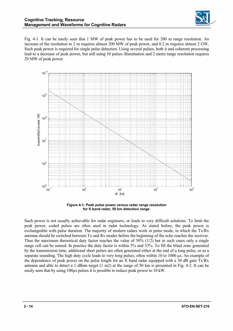
Fig. 4-1. It can be easily seen that 1 MW of peak power has to be used for 200 m range resolution. An increase of the resolution to 2 m requires almost 200 MW of peak power, and 0.2 m requires almost 2 GW. Such peak power is required for single pulse detection. Using several pulses, both it and coherent processing lead to a decrease of peak power, but still using 10 pulses illumination and 2 metre range resolution requires 20 MW of peak power.
Figure 4-1: Peak pulse power versus radar range resolution for X band radar, 50 km detection range.
Such power is not usually achievable for radar engineers, or leads to very difficult solutions. To limit the peak power, coded pulses are often used in radar technology. As stated before, the peak power is exchangeable with pulse duration. The majority of modern radars work in pulse mode, in which the Tx/Rx antenna should be switched between Tx and Rx modes before the beginning of the echo reaches the receiver. Thus the maximum theoretical duty factor reaches the value of 50% (1/2) but in such cases only a single range cell can be sensed. In practice the duty factor is within 5% and 33%. To fill the blind zone generated by the transmission time, additional short pulses are often generated either at the end of a long pulse, or as a separate sounding. The high duty cycle leads to very long pulses, often within 10 to 1000 µs. An example of the dependence of peak power on the pulse length for an X band radar equipped with a 30 dB gain Tx/Rx antenna and able to detect a 1 dBsm target (1 m2) at the range of 50 km is presented in Fig. 4-2. It can be easily seen that by using 100µs pulses it is possible to reduce peak power to 10 kW.
Cognitive Tracking, Resource Management and Waveforms for Cognitive Radars
STO-EN-SET-216 2 - 15
Figure 4-2: Peak pulse power versus coded pulse width for X band radar with 50 km detection range.
Further peak power reduction is possible for a continuous wave. In such radars the transmit and receive processes are performed simultaneously using two separate antennas, one Tx and one Rx. The most popular kind of CW radar is the FMCW (Frequency Modulated Continuous Wave) which typically uses linear frequency modulation. For such radars the peak power of 10-100 W can ensure a detection range of 50 km. As FMCW radars often work with mechanically scanned antennas, the target illumination time is 10-100 ms. Longer illumination times are achieved in noise or pseudo-noise radars, where band limited noise is used as an illuminating signal. The basic concept of noise radar is that it continuously illuminates the surveillance antenna, and a set of fixed received beams are used. In such a concept the illumination time is limited only by the signal processing part and can reach a value of several seconds. Very low transmission power is required for such a long integration time radar, which can be far below 1 W. Thus such a radar belongs to the LPI class (Low Probability of Intercept) and thus is extremely difficult for classical ESM devices to detect and identify.
Classical radars use linear frequency modulation (LFM) to perform range compression. The big advantage of LFM compression is that it is almost insensitive to the Doppler shift of a target echo. A small Doppler shift slightly shifts the peak of compression response in range. This shift can be compensated after the estimation of a target’s radial velocity, using either a staggered batch of pulses (used typically in MTD processing) or velocity data from a tracker.
The big disadvantage is that only two waveforms exist for the given pulse duration and bandwidth, namely up and down chirp. This is usually sufficient for radar sensing in preferable conditions (no jamming, no
Cognitive Tracking, Resource Management and Waveforms for Cognitive Radars
2 - 16 STO-EN-SET-216
interference) but gives only a small area of freedom in cases of heavy interference or jamming. In such difficult conditions different waveforms are required. Candidates for good radar waveforms are found among constant amplitude waveforms that fully exploit the radar transmitter. Constant amplitude signals with phase manipulation are now widely applied in modern radars. A number of such waveforms have been developed in the past. The gallery of such signals opens the binary-phase Barker code [41]. The amplitude of the main peak of the correlation function of the Barker code is equal to the length of the code, while the side lobes are limited to unity. Barker codes up to a length of 13 exist, so the best possible main lobe to side lobe ratio is 22.2 dB. Again the number of unique Barker codes is very low, so now they have mostly historical value. More freedom is given by poly-phase codes. An intensive search of poly-phase unimodular Barker codes led to finding codes of length 19 in 1989 [39] and a length of 65 in 2007 [40]. Other poly-phase codes such as Frank codes [41], and P-codes [42] among others have been also developed.
All of the above mentioned codes have some disadvantages. One of most important is that the code is predefined and usually fixed, so it is easy to detect the radar and for enemy jammers to produce false target echoes.
The second disadvantage is that most polyphone codes have narrow mail lobes both in range (which is a benefit) but also in Doppler frequency, which could be considered a disadvantage.
The range width of the main peak is usually equal to c/2B (the speed of light divided by the doubled signal bandwidth) while the Doppler width is equal to the inverse of pulse time. For example, for a 1ms pulse the main peak is 1 kHz in width, while the fast plane (1000 m/s) produces a Doppler shift of 60 kHz in the X band. As a result it is necessary to compensate the Doppler shift or to use multi-frequency signal compression. In the presented case it would be necessary to use 120 parallel processing channels. Such an approach is used in noise radar, but in the case of a long integration time the number of frequency channels can be much higher (in the order of magnitudes) and multichannel processing is performed using an ambiguity function calculation [43-48].
As the number of classical optimal or quasi optimal codes is also limited, it would be nice to find a more universal approach with good correlation.
The alternatives to predefined fixed codes (waveforms) are random waveforms. They can be generated fully randomly using analogue devices such as a resistor with a chain of amplifiers or noisy Zener diodes, or can be generated digitally using pseudo-random generators. The waveforms can be generated on-line in real time or generated off-line and stored in the radar waveform memory. The noise-like pulses of a length of 10-1000µs and bandwidth of 10MHz to 1 GHz (10 MHz for detection, up to 1 GHz for imaging) have a time bandwidth product in the range of 100-100 000. When the expected time and frequency side lobes are at the level of the time-bandwidth product (20-60 dB) it is possible to decrease the side lobes using non-matched filters or noise shaping, and as a result the side lobes can be decreased by 5-20 dB. In addition such waveforms are almost orthogonal to each other, and it is relatively easy to generate the waveform orthogonal to other selected signals (like jamming signals).Thus such waveforms are almost ideal for MIMO radars, as the sets of transmitting antennas transmit orthogonal waveforms, and generate electromagnetic fields with different properties (different waveforms) at different angles. Such waveforms significantly limit the ability of intelligent jammers to generate false targets, as it is very straightforward to estimate the angular position of a jammer and the angular position of false echoes.
The selection of waveforms has to be made using a cognitive approach [16-38], taking into account the expected behaviour of the jammers.
Cognitive Tracking, Resource Management and Waveforms for Cognitive Radars
STO-EN-SET-216 2 - 17
5.0 REFERENCES
[1] Haykin, Simon, “Cognitive radar: a way of the future,” Signal Processing Magazine, IEEE , vol.23, no.1, pp.30,40, Jan. 2006
[2] Haykin, Simon, “New generation of radar systems enabled with cognition,” Radar Conference, 2010 IEEE , vol., no., pp.1,1, 10-14 May 2010
[4] Baker, C.J.; Griffiths, H.D.; Sammartino, P.F., “MIMO radar: From a different perspective,” Computational Advances in Multi-Sensor Adaptive Processing (CAMSAP), 2009 3rd IEEE International Workshop on , vol., no., pp.185,188, 13-16 Dec. 2009
[5] Zhou, Feng; Zhou, Deyun; Yu, Geng, “Target Tracking in Interference Environments Reinforcement Learning and Design for Cognitive Radar Soft Processing,” Image and Signal Processing, 2008. CISP ‘08. Congress on , vol.4, no., pp.73,77, 27-30 May 2008
[6] Junkun Yan; Bo Jiu; Hongwei Liu; Bo Chen; Zheng Bao, “Prior Knowledge-Based Simultaneous Multibeam Power Allocation Algorithm for Cognitive Multiple Targets Tracking in Clutter,” Signal Processing, IEEE Transactions on , vol.63, no.2, pp.512,527, Jan.15, 2015
[8] Pathan, S.S.; Al-Hamadi, A.; Michaelis, B., “Integrating statistical and cognitive model for multi-object tracking in realistic scenarios,” Image and Vision Computing New Zealand (IVCNZ), 2010 25th International Conference of , vol., no., pp.1,8, 8-9 Nov. 2010
[9] Bell, K.; Baker, C.; Smith, G.; Johnson, J.; Rangaswamy, M., “Cognitive Radar Framework for Target Detection and Tracking,” Selected Topics in Signal Processing, IEEE Journal of , vol. PP, no.99, pp.1,1
[10] Yang Li; Ning Zhang; Qiang Yang, “Cognitive detector: A new architecture for target detection and tracking in complex environment,” Intelligent System and Knowledge Engineering, 2008. ISKE 2008. 3rd International Conference on , vol.1, no., pp.685,688, 17-19 Nov. 2008
[11] Bell, K.L.; Johnson, J.T.; Smith, G.E.; Baker, C.J.; Rangaswamy, M., “Cognitive radar for target tracking using a software defined radar system,” Radar Conference (RadarCon), 2015 IEEE , vol., no., pp.1394,1399, 10-15 May 2015
[12] Jun Yang; Chang-zhou Fan; Hui Wang; Ying Luo; Guo-zheng Wang, “Cognitive Radar Tracking method in Multipath Scenarios Based on Waveform Parameters Design,” Signal Processing, Communications and Computing (ICSPCC), 2014 IEEE International Conference on , vol., no., pp.738,742, 5-8 Aug. 2014
[13] Perlovsky, L., “GMTI tracking improved by 18 dB using cognitive algorithm,” Radar Conference, 2009 IEEE , vol., no., pp.1,3, 4-8 May 2009
[14] Sharaga, N.; Tabrikian, J.; Messer, H., “Optimal Cognitive Beamforming for Target Tracking in MIMO Radar/Sonar,” Selected Topics in Signal Processing, IEEE Journal of , vol.PP, no.99, pp.1,1
Cognitive Tracking, Resource Management and Waveforms for Cognitive Radars
2 - 18 STO-EN-SET-216
[15] Zhou, Feng; Liangliang Zhang; Tong Xu, “Analysis of the maneuvering target tracking method for cognitive radar and simulation studying,” Image and Signal Processing (CISP), 2011 4th International Congress on , vol.1, no., pp.100,104, 15-17 Oct. 2011
[16] Kai Huo; Zhaokun Qiu; Yongxiang Liu; Weidong Jiang, “An adaptive waveform design method for OFDM cognitive radar,” Radar Conference (Radar), 2014 International , vol., no., pp.1,5, 13-17 Oct. 2014
[17] Nijsure, Y.; Chen, Y.; Rapajic, P.; Yuen, C.; Chew, Y.H.; Qin, T.F., “Information-theoretic algorithm for waveform optimization within ultra wideband cognitive radar network,” Ultra-Wideband (ICUWB), 2010 IEEE International Conference on , vol.2, no., pp.1,4, 20-23 Sept. 2010
[18] Aubry, A.; De Maio, A.; Piezzo, M.; Naghsh, M.M.; Soltanalian, M.; Stoica, P., “Cognitive radar waveform design for spectral coexistence in signal-dependent interference,” Radar Conference, 2014 IEEE , vol., no., pp.0474,0478, 19-23 May 2014
[19] Nijsure, Y.; Yifan Chen; Boussakta, S.; Chau Yuen; Yong Huat Chew; Zhiguo Ding, “Novel System Architecture and Waveform Design for Cognitive Radar Radio Networks,” Vehicular Technology, IEEE Transactions on , vol.61, no.8, pp.3630,3642, Oct. 2012
[20] Bin Wang; Jinkuan Wang; Xin Song; Yinghua Han, “A New Waveform Design Method for Cognitive Radar,” Intelligent Information Technology Application, 2009. IITA 2009. Third International Symposium on , vol.2, no., pp.176,179, 21-22 Nov. 2009
[21] Yimin Wei; Huadong Meng; Xiqin Wang, “Adaptive single-tone waveform design for target recognition in Cognitive Radar,” Radar Conference, 2009 IET International , vol., no., pp.1,4, 20-22 April 2009
[22] Bo Jiu; Hongwei Liu; Lei Zhang; Yinghua Wang; Tao Luo, “Wideband cognitive radar waveform optimization for joint target radar signature estimation and target detection,” Aerospace and Electronic Systems, IEEE Transactions on , vol.51, no.2, pp.1530,1546, April 2015
[23] Haykin, Simon; Yanbo Xue; Davidson, T.N., “Optimal waveform design for cognitive radar,” Signals, Systems and Computers, 2008 42nd Asilomar Conference on , vol., no., pp.3,7, 26-29 Oct. 2008
[24] Hao He; Stoica, Petre; Jian Li, “Waveform design with stopband and correlation constraints for cognitive radar,” Cognitive Information Processing (CIP), 2010 2nd International Workshop on , vol., no., pp.344,349, 14-16 June 2010
[25] Bin Wang; Jinkuan Wang; Xin Song; Yinghua Han, “Optimal Adaptive Waveform Selection Based on ADP in Cognitive Radar,” Computer Science and Information Engineering, 2009 WRI World Congress on , vol.5, no., pp.332,334, March 31 2009-April 2 2009
[26] Jo-Yen Nieh; Romero, R.A., “Integrated range-Doppler map and extended target identification with adaptive waveform for cognitive radar,” Radar Conference (RadarCon), 2015 IEEE , vol., no., pp.1644,1649, 10-15 May 2015
[27] Saverino, A.L.; Capria, A.; Berizzi, F.; Dalle Mese, E., “Cognitive adaptive waveform technique for HF skywave radar,” Cognitive Information Processing (CIP), 2010 2nd International Workshop on , vol., no., pp.247,252, 14-16 June 2010
Cognitive Tracking, Resource Management and Waveforms for Cognitive Radars
STO-EN-SET-216 2 - 19
[28] Turlapaty, A.; Yuanwei Jin, “Parameter estimation and waveform design for cognitive radar by minimal free-energy principle,” Acoustics, Speech and Signal Processing (ICASSP), 2013 IEEE International Conference on , vol., no., pp.6244,6248, 26-31 May 2013
[29] Jun Yang; Chang-zhou Fan; Hui Wang; Ying Luo; Guo-zheng Wang, “Cognitive Radar Tracking method in Multipath Scenarios Based on Waveform Parameters Design,” Signal Processing, Communications and Computing (ICSPCC), 2014 IEEE International Conference on , vol., no., pp.738,742, 5-8 Aug. 2014
[30] Piezzo, M.; De Maio, A.; Aubry, A.; Farina, A., “Cognitive radar waveform design for spectral coexistence,” Radar Conference (RADAR), 2013 IEEE , vol., no., pp.1,4, April 29 2013-May 3 2013
[31] Meimei Fan; Dongping Liao; Xiaofeng Ding; Xiang Li, “Adaptive waveform design based on LSSVM for moving target recognition in cognitive radar,” Information Science and Technology (ICIST), 2012 International Conference on , vol., no., pp.405,409, 23-25 March 2012
[32] Fengming Xin; Jinkuan Wang; Bin Wang; Xin Song, “Waveform design for cognitive radar based on information theory,” Multisensor Fusion and Information Integration for Intelligent Systems (MFI), 2014 International Conference on , vol., no., pp.1,8, 28-29 Sept. 2014
[33] Tabrikian, J., “Adaptive waveform design for target enumeration in cognitive radar,” Computational Advances in Multi-Sensor Adaptive Processing (CAMSAP), 2013 IEEE 5th International Workshop on, vol., no., pp.69,72, 15-18 Dec. 2013
[34] Huleihel, W.; Tabrikian, J.; Shavit, R., “Optimal Adaptive Waveform Design for Cognitive MIMO Radar,” Signal Processing, IEEE Transactions on , vol.61, no.20, pp.5075,5089, Oct.15, 2013
[35] Bin Wang; Jinkuan Wang; Jing Li, “ADP-Based Optimal Adaptive Waveform Selection in Cognitive Radar,” Intelligent Information Technology Application Workshops, 2008. IITAW ‘08. International Symposium on , vol., no., pp.788,790, 21-22 Dec. 2008
[36] Huleihel, W.; Tabrikian, J.; Shavit, R., “Optimal sequential waveform design for cognitive radar,” Acoustics, Speech and Signal Processing (ICASSP), 2012 IEEE International Conference on , vol., no., pp.2457,2460, 25-30 March 2012
[37] Setlur, P.; Rangaswamy, M., “Proximal constrained waveform design algorithms for cognitive radar STAP,” Signals, Systems and Computers, 2014 48th Asilomar Conference on , vol., no., pp.143,147, 2-5 Nov. 2014
[38] Setlur, P.; Devroye, N.; Cheng, Z., “Waveform scheduling via directed information in cognitive radar,” Statistical Signal Processing Workshop (SSP), 2012 IEEE , vol., no., pp.864,867, 5-8 Aug. 2012 [1] R. H. Barker, “Group synchronizing of binary digital systems,” in Communications Theory, Butterworth, London, pp. 273–287, 1953
[39] Borwein, P. and Ferguson, R., “Polyphase sequences with low autocorrelation”, IEEE Trans. Inf. Theory, vol. 51, no. 4, Apr. 2005, pp.1564-1567
[40] Borwein, P. and Ferguson, R., “Barker sequences”, poster session, CMSMITACS Joint Conference, Winnipeg, Manitoba, May 31 to June 3,2007
[41] Frank, R. L., “Polyphase codes with good nonperiodic correlation properties”, IEEE Transactions on Information Theory, vol. IT-9, pp. 43–45, 1963
Cognitive Tracking, Resource Management and Waveforms for Cognitive Radars
2 - 20 STO-EN-SET-216
[42] B.L. Lewis and F.F. Kretschmer, “A new class of polyphase pulse compression codes and techniques,” IEEE Trans. AES, vol. AES-17, no. 3, pp. 364-372, May 1981
[43] Liu Guosui; Gu Hong; Su Weimin, Development of random signal radars; Aerospace and Electronic Systems, IEEE Transactions on , Volume: 35 , Issue: 3 , July 1999, Pages:770 – 777
[44] B.M. Horton: Noise-modulated distance measuring system, Proc. IRE, V0147, pp.821-828, May 1959. Reprinted in Radars, Vol. 7, CW and Doppler Radar (D. K. Barton, ed.), Artech House, 1978
[45] G.R. Cooper and C.D. McGillem: Random signal radar, School Electr. Eng., Purdue Univ., Final Report, TREE67-11, June 1967
[46] Craig. S.E, Fishbein, W., Rittenbach, O.E., “Continuous-Wave Radar with High Range Resolution and Unambiguous Velocity Determination”, IRE Trans. Mil Electronics, vol. MIL 6. No. 2. April 1962, pp. 153-161. Reprinted in Radars, Vol. 7, CW and Doppler Radar (D. K. Barton, ed.), Artech House, 1978
[47] Malanowski, M.; Kulpa, K., “Detection of Moving Targets With Continuous-Wave Noise Radar: Theory and Measurements,” Geoscience and Remote Sensing, IEEE Transactions on , vol.50, no.9, pp.3502-3509, Sept. 2012
[48] Kulpa Krzysztof: Signal Processing in Noise Waveform Radar, 2013, Artech House, ISBN 978-1-60807-661-1
[49] J. R. Guerci, Cognitive Radar: The Knowledge-aided Fully Adaptive Approach (Artech House Remote Sensing Library), Artech House, Apr 30, 2010, ISBN-10: 159693364X