Abstract: We compare a simple dynamical model of fiber laser ar-rays with independent experiments on two coupled lasers. The degreeof agreement with experimental observations is excellent.Collectivelythe evidence presented supports this dynamical approach asan alterna-tive to the traditional static eigenmode analysis of the coupled laser cavities.
OCIS codes: (060.2320) Fiber optics amplifiers and oscillators; (140.3290) Laser arrays;(190.3100) Instabilities and chaos.
References and links1. A. Liem, H. Limpert, and A. Tunnermann, “100W single-frequency master-oscillator fiber power amplifier,” Opt.
Lett. 28, 1539 (2003).2. P. Cheo, A. Liu, and G. King, “A high-brightness laser beamfrom a phase-locked multicore Yb-doped fiber laser
array,” IEEE Photon. Technol. Lett.13, 439–441 (2001).3. E. Bochove, P. Cheo, and G. King, “Self-organization in a multicore fiber laser array,” Opt. Lett.28, 1200–1202
(2003).4. C. Corcoran and F. Durville, “Experimental demonstration of a phase-locked laser array using a self-Fourier
cavity,” Appl. Phys. Lett.86, 201,118 (2005).5. V. Apollonov, S. Derzhavin, V. Kislov, V. Kuzminov, D. Mashkovsky, and A. Prokhorov, “Phase-locking of the
2D structures,” Opt. Express4, 19–26 (1999).6. M. Wrage, P. Glas, and M. Leitner, “Combined phase lockingand beam shaping of a multicore fiber laser by
structured mirrors,” Opt. Lett.26, 980–982 (2001).7. N. Lyndin, V. Sychugov, A. Tikhomirov, and A. Abramov, “Laser system composed of several active elements
connected by single-mode couplers,” Quantum Electron.24, 1058–1061 (1994).8. V. Kozlov, J. Hern `andez-Cordero, and T. Morse, “All-fiber coherent beam combining of fiber lasers,” Opt. Lett.
24, 1814–1816 (1999).9. T. Simpson, A. Gavrielides, and P. Peterson, “Extractioncharacteristics of a dual fiber compound cavity,” Opt.
Express10, 1060–1073 (2002).10. A. Shirakawa, T. Saitou, T. Sekiguchi, and K. Ueda, “Coherent addition of fiber lasers by use of a fiber coupler,”
Opt. Express10, 1167–1172 (2002).11. D. Sabourdy, V. Kerm `ene, A. Desfarges-Berthelemot, L. Lefort, A. Barth ´elemy, C. Mahodaux, and D. Pureur,
“Power scaling of fibre lasers with all-fibre interferometric cavity,” Electron. Lett.38, 692–693 (2002).12. D. Sabourdy, V. Kerm `ene, A. Desfarges-Berthelemot, L. Lefort, A. Barth ´elemy, P. Even, and D. Pureur, “Efficient
coherent combining of widely tunable fiber lasers,” Opt. Express11, 87–97 (2003).13. H. Bruesselbach, D. Jones, M. Mangir, M. Minden, and J. Rogers, “Self-organized coherence in fiber laser
arrays,” Opt. Lett.30, 1339–1341 (2005).14. H. Bruesselbach, M. Minden, J. Rogers, D. Jones, and M. Mangir, “200W Self-Organized Coherent Fiber Ar-
rays,” in2005 Conference on Lasers and Electro-Optics (CLEO), vol. 1, p. 532 (2005).15. A. Ishaaya, N. Davidson, L. Shimshi, and A. Friesem, “Intracavity coherent addition of Gaussian beam distribu-
tions using a planar interferometric coupler,” Appl. Phys.Lett. 85, 2187–2189 (2004).16. Q. Peng, Z. Sun, Y. Chen, L. Guo, Y. Bo, X. Yang, and Z. Xu, “Efficient improvement of laser beam quality by
coherent combining in an improved Michelson cavity,” Opt. Lett.30, 1485–1487 (2005).
#106878 - $15.00 USD Received 28 Jan 2009; revised 3 May 2009; accepted 5 May 2009; published 20 May 2009
(C) 2009 OSA 25 May 2009 / Vol. 17, No. 11 / OPTICS EXPRESS 9357
17. B. Lei and Y. Feng, “Phase locking of an array of three fiberlasers by an all-fiber coupling loop,” Opt. Express15, 17114–17119 (2007).
18. D. Mehuys, K. Mitsunaga, L. Eng, W. Marshall, and A. Yariv, “Supermode control in diffraction-coupled semi-conductor laser arrays,” Appl. Phys. Lett.53, 1165–1167 (1988).
19. D. Sabourdy, A. Desfarges-Berthelemot, V. Kerm `ene, and A. Barth ´elemy, “Coherent combining of Q-switchedfibre lasers,” Electron. Lett.40, 1254–1255 (2004).
20. J. Rogers, S. Peles, and K. Wiesenfeld, “Model for high-gain fiber laser arrays,” IEEE J. Quantum Electron.41,767–773 (2005).
21. W. Ray, K. Wiesenfeld, and J. L. Rogers, “Refined fiber laser model,” Phys. Rev. E78, 046203 (2008).22. A. Shirikawa, K. Matsuo, and K. Ueda. “Fiber laser coherent array for power scaling of single-mode fiber laser,”
Proc. SPIE5662, 482–487 (2004).23. A. Shirakawa (personal communication, 2007).24. P. Le Boudec, M. Le Flohic, P. Francois, F. Sanchez, and G.Stephan, “Self-pulsing in Er3+-doped fibre laser,”
Opt. Quantum Electron.25, 359–367 (1993).25. E. Lacot, F. Stoeckel, and M. Chenevier, “Dynamics of an erbium-doped fiber laser,” Phys. Rev.A 49, 3997–4008
(1994).26. S. Bielawski and D. Derozier, “Dynamics of a Nd-doped fiber laser: c.w. and self-pulsing regimes, stabilization,”
J. Phys. III France5, 251–268 (1995).
1. Introduction
Recognizing the power limitations of individual lasers, researchers have tried to develop meth-ods of combining light from an array of semiconductor or fiberlasers to obtain an efficienthigh-power source. Extensive investigations have evaluated various coupling architectures withthe goal of promoting coherent addition in the far-field of the light emitted from the outputreflectors of individual lasers. Inphase array emission, where all constituent lasers operate at acommon frequency and with zero relative phase difference, has been demonstrated using activecontrol of the phases [1] and with passive coupling schemes including multicore fibers [2, 3],self-Fourier cavities [4], and Talbot resonators [5,6]. These coupling devices often suffer fromalignment issues, stability problems due to low threshold differences between array solutions,or increased cavity losses in their implementation.
An alternative approach has recently been developed to enforce coherent beam combina-tion in arrays [7, 8, 9, 10, 11, 12, 13, 14]. In addition to a passive coupling arrangement amongthe elemental lasers, losses incurred at the individual output facets are purposely imbalanced.Experimental investigations have reported emission of inphase coherent light solely from theoutput reflector having the lowest losses. This form of single-facet emission has been studiedprimarily in arrays of solid-state and fiber lasers using interferometric coupling devices such asbeam splitters [15, 16], fold mirrors [14], or directional couplers [8, 9, 10, 11, 13, 17]. In mostrealizations only one coupler output is fitted with a reflector to provide a global feedback forthe entire array.
Although well-documented experimentally, few model descriptions have studied this config-uration of coherent beam combining. In one depiction [9], the array of coupled lasers is treatedas a single compound-cavity laser. The intrinsic laser dynamics are ignored and coherent beamcombination is discussed in terms of the static eigenmodes,often referred to as supermodes,of the compound-cavity setup [18]. Although an analysis of these solutions provides impor-tant considerations necessary for inphase emission from a single output facet, the validity ofthis description is limited to continuous-wave (cw) emission for pump strengths very close tothreshold. In contrast, experiments have shown high addition efficiency in pulsing Q-switchedfiber lasers [19] and at pump strengths extending far above threshold where the output lightoften exhibits more complicated dynamics such as self-pulsing.
In this paper we investigate the phenomenon of coherent emission from a single output facetusing an iterative map model recently introduced to describe the dynamics of fiber laser ar-rays [20]. Simulations of two coupled lasers with experimentally derived parameters robustly
#106878 - $15.00 USD Received 28 Jan 2009; revised 3 May 2009; accepted 5 May 2009; published 20 May 2009
(C) 2009 OSA 25 May 2009 / Vol. 17, No. 11 / OPTICS EXPRESS 9358
Fig. 1. Experimental schematic of two coupled lasers. Each laser gain block is terminatedby a fiber Bragg grating (FBG) at one end and a high-loss outputfacet at the other with fieldreflection coefficientsr1 andr2. A 50/50 directional coupler allows light to interact over asmall distance of the fiber lengths. The labelsE1 andE2 indicate the frame of reference forEq. (1).
produce coherent inphase emission of light entirely from the output facet with lowest losses,even when there is only a small mismatch in output losses [10]. Furthermore, the model showsagreement with experimental results in the presence of an additional detuning of the individualpump currents from optimal operating conditions [7,9].
A significant feature of the iterative map model is the treatment of each individual laser asa separate dynamical oscillator influenced by the other laser via a passive, lossless coupler.Our numerical computations are consistent with a static description of the system provided bysupermode theory within the latter’s range of validity. In addition, the dynamical model robustlyreproduces the experimental observations over a large range of pumping values spanning bothcw and pulsing dynamical regimes.
2. Model description
The experiments we consider use the setup schematically illustrated in Fig. 1. Each laser cavityis formed by a fiber Bragg grating (FBG) providing nearly 100%reflection on one end anda high-loss output facet at the other end typically reflecting only about 4% of the incidentintensity. A joint coupling region, most often manifested as a 50/50 fused fiber coupler, liesbetween the individual gain blocks and the output facets.
2.1. Iterative maps
We recently introduced a dynamical model for a general classof fiber laser arrays which in-cludes the setup of Fig. 1 as a special case. A set of nonlinearcoupled iterative maps tracesthe evolution of the electric field and gain of each laser overone round trip. In a three-levellasing scheme, the forward-travelling electric fieldsE1,2 and gainsG1,2 of the individual fibers,starting in Fig. 1 immediately before the output coupler, are explicitly transformed in one passthrough their respective cavities over a round-trip timeT according to [20,21]
En(t + T ) = eGn(t)+ jφ Ln
2
∑ℓ=1
Snℓejφ R
ℓ rℓ
2
∑m=1
SℓmEm(t), (1)
Gn(t + T ) = Gn(t)+ ε[
xW pth,nτ (Gtot −Gn(t))− (Gtot + Gn(t))
]
(2)
−2εIsat
(
1− e−2Gn(t))
|En(t)|2 .
#106878 - $15.00 USD Received 28 Jan 2009; revised 3 May 2009; accepted 5 May 2009; published 20 May 2009
(C) 2009 OSA 25 May 2009 / Vol. 17, No. 11 / OPTICS EXPRESS 9359
After an initial pass through the coupler, denoted by the matrix S in Eq. (1), the emergingelectric fields propagate towards the output facets with respective reflection coefficientsr1,2.The output facets are assumed to be the only source of cavity losses. The light reflected fromeach output face then reenters the coupler and passes through the individual gain arms beforefinally arriving at the starting point. The amplification of the fields due to the back-and-forthpropagation through the gain sections is characterized by exponential gainseG1,2.
The round-trip time is assumed to be the same for each laser. However, small differencesinevitably exist in the length and propagation constant of each cavity. At a given operationalfrequency, these differences are captured by assigning individual phase shifts acquired in afull round trip through each constituent laser. The phase shift acquired in each cavity over oneround trip characterizes the assumed optical frequency ofE1,2. In writing these equations, wehave explicitly separated the total phase shift into three parts:φL
1,2 is the phase shift acquiredduring transit through the individual gain arms on the left-hand side of the coupler;φR
1,2 denotesthe phase shift picked up from propagation through the region on the right-hand side of thecoupler; and the phase shift gained in the coupling region iscontained in the coupling matrixS.This separation of the acquired phase shifts is important when we consider the conditions foremission from a single facet when an imbalance exists in the losses from the individual outputfacets. These parameters solely influence the phase shift acquired in each constituent laser asthere are no nonlinearities in Eq. (1) associated with gain-or intensity-dependent phase shifts.
The evolution equation for the gain, Eq. (2), details operation of a fiber laser in a three-levelscheme [21]. We adopt this form since the experiments we consider used erbium-doped fiberlasers. The relative pump ratex is the ratio of the applied pump rate to the pump rate at lasingthresholdW p
th,n. The total available gain in each laserGtot is proportional to the stimulatedemission cross section and obtainable population inversion. The parameterε sets the time scalefor the gain dynamics and is the ratio of the round trip time inthe cavity toτ, the fluorescencetime of the inversion. The saturation intensityIsat dictates the average power emitting fromeach fiber laser. We note that although the form of Eqs. (1,2) is an accurate description of three-level operation of erbium-doped amplifying elements, the model does not capture ground-levelabsorption losses or pump absorption saturation effects associated with the presence of largepump and laser signals.
2.2. Coupling
Although many optical devices have been developed to couplelight between individual lasers,directional couplers are often used since it is not necessary for light to enter or exit the opticalwaveguides in any part of the array. These evanescent couplers are typically formed by heatingand pulling a packed bundle of fibers. Over an interaction region d the individual fiber coresare sufficiently narrow to release light into the shared cladding of the fiber bundle.
We have previously derived a general formulation to describe passive linear coupling for anarbitrary number of interacting fibers [20]. A directional coupler between two waveguides maybe succinctly characterized by the propagation constantsβ1,2 for light remaining within a givenfiber through the coupling region and the propagation constants κ12 and κ21 describing theperturbation of light entering from the other fiber. For a symmetric coupler withβ1 = β2 = βandκ12 = κ∗
21 = κ (a real constant in a loss-less coupler), the coupling matrix S may be writtenas
S = e jβ d(
cos(κd) jsin(κd)jsin(κd) cos(κd)
)
. (3)
In this form it is clear that the light sloshes back-and-forth through the coupling region as afunction of the interaction length. While it is difficult to experimentally determine the overall
#106878 - $15.00 USD Received 28 Jan 2009; revised 3 May 2009; accepted 5 May 2009; published 20 May 2009
(C) 2009 OSA 25 May 2009 / Vol. 17, No. 11 / OPTICS EXPRESS 9360
phaseβ d acquired in the coupler, one may easily characterizeκd by measuring how powerentering from one fiber distributes to the two output fibers. We consider 50/50 power splittersin this study, which requiresκd to be an odd multiple ofπ4 . Any odd multiple may be used inthe simulations, as other choices only differ by an overall phase shift that may be absorbed intoβ d.
3. Coherent beam combination
Inphase combination of light from two coupled fiber laser elements out of a single output facetwas first reported by Lyndinet al. in 1994 [7]. Since then a number of research groups haveobserved this phenomenon using a variety of coupling configurations. Kozlovet al. enforcedcoherent addition between two lasers by forming a common output facet from one half of adirectional coupler [8]. A majority of investigations havebeen performed, however, using asetup similar to the one in Fig. 1. A common output facet is selected by detuning the amount ofloss incurred at the two output facets. More recent studies have shown high addition efficienciesof four, five, and even eight lasers using a hierarchical nesting of 2x2 couplers [10,13,22].
In this section we compare predictions of the iterative map model, Eqs. (1,2), with threefeatures of coherent combining observed in experimental realizations of this system. The firststep is to set the model parameters (see Table 1).
Table 1. Parameter values used for simulations of two coupled lasers. The operating condi-tions are estimated from an empirical characterization of this system found in Ref. [9].
Parameter Description Value Units
T round-trip time 163.2 nsτ fluorescence time 10 msε ratio of round-trip to fluorescence time 1.632×10⁻⁵ dimensionless
Gtot total linear gain 9.21 dimensionlessrn output facet reflection coefficient varies dimensionless
W pth,n pumping at laser threshold varies s−1
x pumping relative to lasing threshold varies dimensionlessIEXP,SIMsat saturation intensity varies dimensionless
3.1. Model parameters
The experimental investigations we consider were performed by two research groups usingcomparable setups of two fiber lasers linked by a single directional coupler. As each setup usesthe same active medium with large cavity lengths, we draw information supplied by one of themto set the model parameters for all comparisons. In the experiments of Simpsonet al. [9], twohigh-gain erbium-doped fibers were joined with a 50/50 coupler and capped on the one endwith high-reflecting fiber Bragg gratings. The lengths of thetwo fiber arms containing the gainelements were approximately 14m but were not identical. One of the two coupler outputs wasflat-cleaved providing a reflection of 4% of the intensity back into the cavity while the otherwas angle-cleaved to minimize any back reflection. Each output fiber had a length of roughly2 m.
With a reported single pass gain of 40dB in each active gain medium, the total lineargain parameter may be estimated asGtot = 9.21 [9]. The round-trip time of the each cav-ity T = 163.2 ns is computed using an index of refraction of 1.53 and total length of 16m.Taking a fluorescence time ofτ = 10 ms for each erbium-doped fiber yields an estimate of
#106878 - $15.00 USD Received 28 Jan 2009; revised 3 May 2009; accepted 5 May 2009; published 20 May 2009
(C) 2009 OSA 25 May 2009 / Vol. 17, No. 11 / OPTICS EXPRESS 9361
ε = 1.632×10⁻⁵. As discussed in the previous section the coupling parameters must be se-lected to produce the power splitting effects of a 50/50 directional coupler. Consequently wechooseκ = 0.001µm−1 andd = 13351.7646µm. Additionally, we setβ = 8 µm−1 althoughthis propagation constant is shared by light from both lasers and its value does not affect theoutput of the system.
A vast majority of the losses occur at the output facets, so the field reflection coefficientsare set to ber1 = 0.20 for the flat-cleaved output facet andr2 = 0 for the laser with the angle-cleave. In this setup the value ofφR
2 does not affect the system since no light is reflected fromthe angle-cleaved port. Similarly the value ofφR
1 does not alter the dynamics because this phaseshift is the same for light entering from both gain arms. Since we are free to choose these angleswe setφR
1 = φR2 = 0. In conrast, the choice of the phase shifts obtained duringtransit through
the two gain arms is important. In particular, therelative phase shift ∆φL = φL2 − φL
1 affectsthe partitioning of light emitted from the two output ports in the steady state. It is important tonote that the relative phase shift does not assign the transmission characteristics of a particularoutput port. The fraction emitted from each output port is instead influenced by the imbalanceof the facet reflection coefficients. We observe that∆φL must be equal to an odd multiple ofπto achieve emission from only one output facet so we setφL
1 = π andφL2 = 0.
In the following comparisons, the experimental and simulated outputs of the coupled lasersystem are evaluated relative to the output of a single lasermember. The single laser intensitygenerated from model computations is matched via assignment of Isat to the correspondingsingle laser experimental measurements over the investigated range of input pumping. Thevalue ofW p
th,n is taken to be the same for both lasers, but its value depends on the particularexperimental investigation being simulated. Specifically, one investigation reports single laserresults of an individual (uncoupled) laser while the other reports results when one laser inthe coupled array is pumped. With matched single laser results, the experimental and predictedoutputs of the coupled system can then be quantitatively compared under a variety of pump ratesand operating conditions. This method of evaluation also allows access to metrics commonlyused to assess the overall performance of coherently combined laser systems. One metric wewill use is the addition efficiency, an estimation of the fraction of light emitted from each outputport compared to the sum of the outputs of the uncoupled lasers.
(It is also necessary to make comparisons in this manner because the experimental measure-ments are reported in terms of emitted powers or voltages from detection equipment. Sinceefficiencies of the pump or detection electronics are not given, we cannot directly calibrate theoutput of our model with the recorded experimental results.)
3.2. Power extraction
We first examine coherent combining in a symmetrically pumped array of two lasers. Fig-ure 2(a) depicts experimental power extraction measurements performed by Shirakawaet al.for increasing levels of the pump [23]. For reference the solid line plots the power output char-acteristics of a single fiber laser detached from the couplerwith a flat-cleaved output facet. Thepumping is reported relative to lasing threshold of the single laser and the intensity is dividedby the average intensity of the laser measured at a pump valueof 50 times the lasing threshold.In the case of two coupled lasers, the power extracted from the two output ports is displayedby the circles in Fig. 2(a). The filled circles represent the average intensity emanating fromthe flat-cleaved output facet associated with the first laser, while the open circles depict theaverage intensity from the very high-loss angle-cleaved output facet of the second laser. Wesee that almost all light emits from the flat-cleaved output facet with the lowest losses, andno light is observed from the angle-cleaved output facet. Comparison with the individual laserextraction shows that, although both have the same lasing threshold, the slope efficiency of the
#106878 - $15.00 USD Received 28 Jan 2009; revised 3 May 2009; accepted 5 May 2009; published 20 May 2009
(C) 2009 OSA 25 May 2009 / Vol. 17, No. 11 / OPTICS EXPRESS 9362
0 20 40 600
0.5
1
1.5
2
2.5
3
Pump / Pumpth
Sim
. Avg
. In
ten
sity
/ I S
AT
SIM
0 20 40 600
0.5
1
1.5
2
2.5
3
Pump / Pumpth
Exp
. Avg
. In
ten
sity
/ I S
AT
EX
P (b)(a)
Fig. 2. Power output characteristics for individual and twocoupled lasers with imbalancedlosses at the output facets. The solid line represents the average intensity produced by asingle laser removed from the array. The filled (open) circles represent the average intensityoutput from the low (high) loss output facet for two coupled and symmetrically pumpedlasers. (a) Experiment using two coupled erbium-doped fiberlasers [23]. (b) Simulationusing iterative map model. For (a) and (b) the pumping is taken relative to lasing thresholdfor a single, uncoupled laser. The intensity axis in each panel is taken relative toIEXP,SIM
sat ,the respective single laser intensity at 50 times the lasingthreshold.
symmetrically pumped lasers is nearly twice that of the single laser demonstrating a 93% com-bining efficiency [10]. The results of Fig. 2(a) are in agreement with other experimental powerextraction curves showing combining efficiencies up to 99% [11].
The power extraction predicted from model computations is shown in Fig. 2(b). The solidline in this figure represents the average intensity obtained for a single uncoupled laser. Similarto the presentation of the experimental data in Fig. 2(a), the pump is shown relative to pumpthreshold and the intensity is taken relative to emission at50 times the lasing threshold. Modelsimulations indicate thatW p
th,n = 1.4235 andISIMsat = 473.45 for an individual laser. The circles
in Fig. 2(b) plot the predicted outputs of the modeled array.The filled (open) circles representthe average intensity emitting from the output port with lower (higher) losses. In the simulationemission from the flat-cleaved port completely dominates the output with an addition efficiencyof 100%.
It is worthwhile to point out that efficient coherent beam combination is observed in themodel computations regardless of the time-resolved intensity dynamics predicted for the sys-tem. In particular, for both coupled and uncoupled lasers, emission in the cw state is observedonly at pump strengths in the range 1< x < 1.1255 above threshold. The intensity and gaindynamics exhibit self-pulsing at higher relative pump rates. As the pump is further increasedthe height and frequency of the pulses rise linearly while the width of an individual pulse de-creases. Although not all fiber laser systems suffer from theself-pulsing instability, it mostoften appears at pump levels near threshold in high-gain fiber lasers operated with heavy cav-ity losses [24, 25, 26]. However, the underlying dynamical state does not affect time-averagedextraction curves from single or coupled lasers because thetime-averaged intensity of a pulsetrain is identical to the value of the unstable cw state at a given pump rate [21].
#106878 - $15.00 USD Received 28 Jan 2009; revised 3 May 2009; accepted 5 May 2009; published 20 May 2009
(C) 2009 OSA 25 May 2009 / Vol. 17, No. 11 / OPTICS EXPRESS 9363
3.3. Detuning of the pump sources
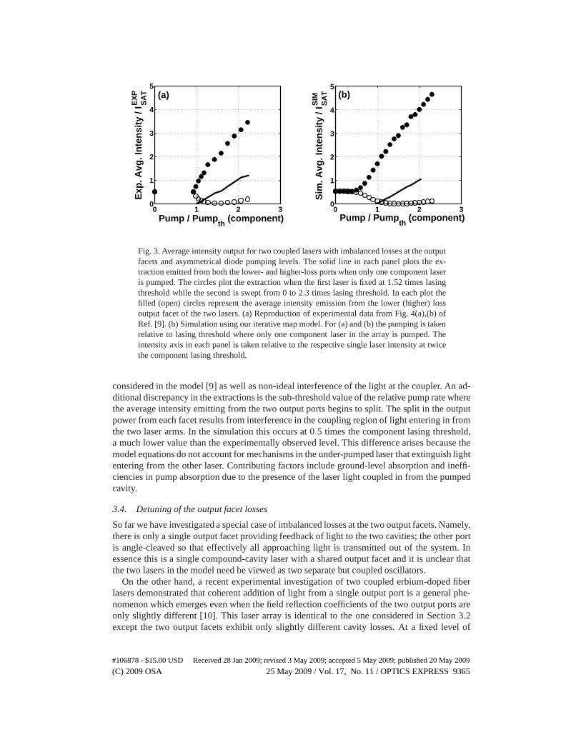
In the previous section the lasers were operated in a symmetrical fashion, including equal levelsof pumping applied to each fiber arm. We now examine what happens when there is a mismatchin the individual pump strengths. For comparison in Fig. 3(a) we reproduce the data shown inFig. 4 of Ref. [9], an experimental realization of two extractions where one laser is fixed to aparticular pump value and the pump strength of the second laser is detuned around the fixedvalue.
The first extraction measurement involves setting the pump strength of the first laser to zeroand increasing the pump strength of the second laser. The solid line in Fig. 3(a) plots the time-averaged output obtained from the flat- and angle-cleaved output ports. In this case the intensityemitted from each output port is the same at all pump levels since light amplified in a single gainarm is split evenly in the 50/50 coupler. This extraction serves as a reference for the output ofa single laser, although this component laser incurs more losses than an individual (uncoupled)laser due to the presence of the coupler in the laser cavity. The pump strength is reported hererelative to the observed lasing threshold and the intensityis taken relative to the emission fromone of the output ports when the component laser is pumped at twice the lasing threshold.
For the second experimental extraction measurement, the pump strength of the first laser isset to 1.52 times the lasing threshold of the component extraction curve and the second laseris tuned from 0 to 2.2 times lasing threshold. In Fig. 3(a) the filled circles represent time-averaged emission from the flat-cleaved output facet while the open circles depict the intensityfrom the angle-cleave of the second laser. When the second laser pump is less than 0.9 times thecomponent lasing threshold, the two output facets emit at equal intensity levels. At higher pumpstrengths the flat-cleaved light output is seen to increase linearly while the angle-cleaved outputtends toward zero. After the pump of the second laser is raised above the fixed pump level ofthe first laser, the intensity emerging from the angle-cleaved output is observed to increase.
Figure 3(b) shows the corresponding extraction curves we find from simulations of Eqs. (1,2).As in the experiment, we first fix the pump of one laser to zero and sweep the second laser pumpuntil about twice the observed lasing threshold. The simulations similarly predict an equal levelof emission from the flat- and angle-cleaved output ports over the range of the second laserpump. This sweep yields the assignment ofW p
th,n = 1.6667 andISIMsat = 144.83 for the component
laser. All other model parameters remain as before. The solid line in Fig. 3(b) plots the scaledsimulated extraction.
The second power extraction is computed by setting the pump of the first laser to 1.52 timesthe component lasing threshold and sweeping the pump of the second laser. The relative pumprate of the first laser is high enough that the intensity dynamics are in the pulsing regime for allinvestigated pump levels of the second laser. The filled circles in Fig. 3(b) represent emissionfrom the output port terminated by a flat-cleave and the open circles show the intensity fromthe angle-cleave. It is immediately clear that the intensity from the angle-cleaved port follows atrend similar to the experimental measurement. A minimum inthis output is realized when thetwo laser pumps are identical.
The emergence of light from the angle-cleaved output port inthis extraction can be explainedby a linear analysis of interference in the 50/50 coupler [12]. When light from back-reflectionoff the output port splits equally into the two gain sections, the intensities are magnified bydifferent amounts. Following amplification, the contrast of the imbalanced intensities reenteringthe coupler towards the output reflector results in incomplete destructive interference into theangle-cleaved output port.
It is apparent in Fig. 3 that the simulated extraction demonstrates a higher degree of coher-ent combining than the experimentally reported extractionat all considered pump levels. Theinefficient beam combining observed in the experiment is dueto internal losses of light not
#106878 - $15.00 USD Received 28 Jan 2009; revised 3 May 2009; accepted 5 May 2009; published 20 May 2009
(C) 2009 OSA 25 May 2009 / Vol. 17, No. 11 / OPTICS EXPRESS 9364
0 1 2 30
1
2
3
4
5
Pump / Pumpth
(component)
Exp
. Avg
. In
ten
sity
/ I E
XP
SA
T (a)
0 1 2 30
1
2
3
4
5
Pump / Pumpth
(component)
Sim
. Avg
. In
ten
sity
/ I S
IM S
AT (b)
Fig. 3. Average intensity output for two coupled lasers withimbalanced losses at the outputfacets and asymmetrical diode pumping levels. The solid line in each panel plots the ex-traction emitted from both the lower- and higher-loss portswhen only one component laseris pumped. The circles plot the extraction when the first laser is fixed at 1.52 times lasingthreshold while the second is swept from 0 to 2.3 times lasing threshold. In each plot thefilled (open) circles represent the average intensity emission from the lower (higher) lossoutput facet of the two lasers. (a) Reproduction of experimental data from Fig. 4(a),(b) ofRef. [9]. (b) Simulation using our iterative map model. For (a) and (b) the pumping is takenrelative to lasing threshold where only one component laserin the array is pumped. Theintensity axis in each panel is taken relative to the respective single laser intensity at twicethe component lasing threshold.
considered in the model [9] as well as non-ideal interference of the light at the coupler. An ad-ditional discrepancy in the extractions is the sub-threshold value of the relative pump rate wherethe average intensity emitting from the two output ports begins to split. The split in the outputpower from each facet results from interference in the coupling region of light entering in fromthe two laser arms. In the simulation this occurs at 0.5 times the component lasing threshold,a much lower value than the experimentally observed level. This difference arises because themodel equations do not account for mechanisms in the under-pumped laser that extinguish lightentering from the other laser. Contributing factors include ground-level absorption and ineffi-ciencies in pump absorption due to the presence of the laser light coupled in from the pumpedcavity.
3.4. Detuning of the output facet losses
So far we have investigated a special case of imbalanced losses at the two output facets. Namely,there is only a single output facet providing feedback of light to the two cavities; the other portis angle-cleaved so that effectively all approaching lightis transmitted out of the system. Inessence this is a single compound-cavity laser with a sharedoutput facet and it is unclear thatthe two lasers in the model need be viewed as two separate but coupled oscillators.
On the other hand, a recent experimental investigation of two coupled erbium-doped fiberlasers demonstrated that coherent addition of light from a single output port is a general phe-nomenon which emerges even when the field reflection coefficients of the two output ports areonly slightly different [10]. This laser array is identicalto the one considered in Section 3.2except the two output facets exhibit only slightly different cavity losses. At a fixed level of
#106878 - $15.00 USD Received 28 Jan 2009; revised 3 May 2009; accepted 5 May 2009; published 20 May 2009
(C) 2009 OSA 25 May 2009 / Vol. 17, No. 11 / OPTICS EXPRESS 9365
0 10 200
1
2
3
Applied Loss (%)Exp
. Avg
. In
ten
sity
/ I E
XP
SA
T
0 10 200
1
2
3
Applied Loss (%)Sim
. Avg
. In
ten
sity
/ I S
IM S
AT
0 10 200
1
2
3
Applied Loss (%)Sim
. Avg
. In
ten
sity
/ I S
IM S
AT
0 5 10 15 20 25 300
50
100
150
Time (µs)Sim
. In
ten
sity
/ I S
IM S
AT
(a) (b) (c)
(d)
Fig. 4. (a)-(c) Plot of average intensity output as a function of the applied losses at theoutput facet of the first laser. The losses of the second laserare 9% higher than the lossesof the first laser without applied losses. The filled (open) circles show the average intensitymeasured from the first (second) laser. Data shown for (a) experiment [reproduction ofFig. 4 from Ref. [10]] (b) simulation without noise (c) simulation with noise. (d) Intensitytime trace from simulation with noise for applied loss levelof 8%. The thin (thick) lineplots pulses from first (second) laser. Values ofIEXP,SIM
sat represent the experimental andsimulated single laser intensity at 50 times the lasing threshold.
identical pumping in each constituent laser, the losses in the lower-loss output arm were grad-ually increased until the total loss in this fiber port exceeded those of the other output facet.The observed average intensity from each output facet is displayed in Fig. 4(a) as the appliedloss in the lower-loss arm (filled circles) is increased from0% to 20%. The losses in the secondfiber port (open circles) are fixed at a level of 9% higher than the lower-loss fiber port withoutapplied loss. For a large detuning between the losses in output arms, the entirety of the emittedlight was seen to reside in the output port with the lowest level of loss. Close to the transitionpoint at 9% applied loss, the power measurements were unstable and light emerged from bothoutput facets.
To replicate this experiment, we use the same model parameters as in Section 3.2 exceptthat we now use one of the reflection coefficients as a control parameter. In particular, we leaver1 = 0.2 for the flat-cleaved output face and now setr2 = 0.1908 to produce a 9% greater loss ofintensity at the output face. Since the reflection coefficient of the second laser is now nonzero,the assignment ofφR
2 is no longer trivial. Nevertheless, when∆φL = π the choice ofφR1 and
φR2 does not affect the outcome of the simulations. We again arbitrarily setφR
1 = φR2 = 0. The
simulated pump level is set to 62.5 times the lasing threshold for an individual (uncoupled)laser to match the average intensity measured in the experiment. At this pumping the intensitydynamics of the model exhibit irregular self-pulsations.
In Fig. 4(b) we plot the simulation results asr1 is decreased from 0.2 to 0.179, representing a20% increase in the losses from this output port. The filled (open) circles represent the intensityemitted from the output facet of the first (second) laser. There is excellent agreement with
#106878 - $15.00 USD Received 28 Jan 2009; revised 3 May 2009; accepted 5 May 2009; published 20 May 2009
(C) 2009 OSA 25 May 2009 / Vol. 17, No. 11 / OPTICS EXPRESS 9366
Fig. 4(a), and a sharp transition in the emission characteristics occurs once the losses in thefirst laser are greater than 9%. When the losses between the two lasers differ by less than 1%,the transients of the intensity in the simulations are very long but eventually the system settlesdown to emission from just one output port.
The unstable emission characteristics experimentally observed in the transition region maybe captured by the addition of a small amount of Langevin noise to the electric field map Eq. (2).Figure 4(c) plots the average intensity measured from each output facet for a noise amplitude of0.02. The addition of noise provides a smoothing effect in the transition region and one outputfacet is no longer completely dominant. In Fig. 4(d) we show asimulated intensity time seriesfor an applied loss of 8%. The thin (thick) line denotes the intensity from the first (second) laser.The first laser emits a majority of the system output. The light from the second laser behavesmore erratically and the pulses occasionally reach higher intensities than those emitting fromthe first laser.
4. Discussion: static vs. dynamic perspectives
The coherent addition of lasers observed in these kinds of experiments is traditionally inter-preted within a static framework of coupled optical waveguides without any regard to the am-plification of the light in the gain medium. The stripped-down coupled cavity is then treatedas a single entity, and the resulting eigenmodes of the system, sometimes called supermodes,are then analyzed as the basis to describe the observed dynamics in the laser. It is typicallypostulated that the lowest loss supermode will “win” by emerging as the stable state, althoughgrowth or decay of individual eigenmodes are rarely quantified.
For example, when two coupled lasers are identical except for an imbalance in the outputfacet reflection coefficients, it is intuitive that losses can be minimized if all of the light isfunneled to the output port with the higher reflectivity. When the cavity conditions are specifiedsuch that the light propagating back-and-forth through thetwo (now passive) gain arms cappedwith 100% reflectors pick up a relative phase shift ofπ , then two constructive supermodes resultwhich funnel light to either one or the other output port [10]. The supermode associated withthe lower-loss output port retains more light each round-trip and consequently will be selectedby the laser system. In fact, this supermode will be globallyselected over other supermodesformed from other cavity configurations where the relative phase shift in the gain arms is notequal toπ , since for these non-optimal relative phase shifts light will invariably be funneled tothe higher-loss port.
The current description offers an alternative to this static perspective. We have shown thatincluding gain as a dynamical variable and treating each laser as a separate oscillator doesequally well at predicting the experimentally observed behavior in the linear (cw) regime. Pref-erential emission from the lowest-loss output port is a direct consequence of the dynamicalinterplay between the gain elements and the imbalanced losses at the output facets. In additionthe dynamical model also extends correct predictions far beyond threshold and even into thepulsing regime. Indeed, the coupling between the two laserstends to align the pulse bursts ofthe individual lasers so that constructive interference isachieved in the coupler at all times.
It is natural to ask about the robustness of the theory with respect to inevitable imperfections,for example in the coupler. We tested this by repeating all ofthe simulations using a 49/51coupler; in all cases the new numerical data lie extremely close to the old. Roughly speaking,the effects appear to vary as the square of the mismatch from 50/50 coupling: for example, inthe extraction plot shown in Fig. 2 the amount exiting from the angle cleave is less than 0.1%of the light of the individual laser (no light exits the anglecleave in the 50/50 coupler).
Although this model reveals a mechanism for selecting whichof the two output ports (su-permodes) receives a larger share of the light, it does not explain in a fundamental sense the
#106878 - $15.00 USD Received 28 Jan 2009; revised 3 May 2009; accepted 5 May 2009; published 20 May 2009
(C) 2009 OSA 25 May 2009 / Vol. 17, No. 11 / OPTICS EXPRESS 9367
relative amount of light emitted from each. This partitioning depends only on the value of∆φL,a manually set parameter in this model, and we have fixed∆φL = π to simulate the nearlycomplete beam-combining observed experimentally. Even though multiple thousands of longi-tudinal modes may potentially oscillate in a fiber laser, only some of these are characterizedby this value of∆φL. A direction of future research would be the extension of this model toa multimode framework allowing simultaneous oscillation of modes characterized by different∆φL. Competition among these modes may shed light on the dynamical selection of frequen-cies associated with this optimal relative phase shift. Additionally, from this groundwork theinfluence of optical nonlinearities relevant at higher powers, such as stimulated Brillion scat-tering and stimulated Raman scattering, may be directly assessed by appropriate extensions ofthe model. These observations demonstrate the importance of a dynamical model in developingan understanding of organized behavior in coupled laser systems.
Acknowledgment
We thank Akira Shirakawa for valuable discussions and providing his original data for our use.This work was supported by the High Energy Laser Joint Technology Office and the US ArmyResearch Office under Award No. W911NF-05-1-0506. Any opinions, findings, and conclu-sions or recommendations expressed in this publication arethose of the authors and do notnecessarily reflect the views of the High Energy Laser Joint Technology Office or the ArmyResearch Office.
#106878 - $15.00 USD Received 28 Jan 2009; revised 3 May 2009; accepted 5 May 2009; published 20 May 2009
(C) 2009 OSA 25 May 2009 / Vol. 17, No. 11 / OPTICS EXPRESS 9368