Page 1
1
COHERENT BINARY MODULATION TECHNIQUES
As mentioned previously, binary modulation has three basic
forms: amplitude-shift keying (ASK), phase-shift keying (PSK),
and frequency-shift keying (FSK). In this section, we present the
noise analysis for the coherent detection of PSK and FSK signals,
assuming an additive white Gaussian noise (AWGN) model.
4 . 1 C o h e r e n t B i n a r y P S K
• In a coherent binary PSK system, the pair of signals, s1(t) and
s2(t), used to represent binary symbols 1 and 0, respectively, are
defined by
where 0 ≤ t < Tb and Eb is the transmitted signal energy per hit.
• In order to ensure that each transmitted bit contains an integral
number of cycles of the carrier wave, the carrier frequency fc =
nc/Tb for some fixed integer nc.
• A pair of sinusoidal waves that differ only in a relative phase-
shift of 180 degrees, as defined above, are referred to as
antipodal signals.
4.1
4.2
Page 2
2
• From Eqs. 4.1 and 4.2, it is clear that there is only one basis
function of unit energy, namely
• Then we may expand the transmitted signals s1(t) and s2(t) in
terms of φ(t) as follows
• A coherent binary PSK system is therefore characterized by
having a signal space that is one-dimensional (i.e., N = 1) and
with two message points (i.e., M = 2), as shown in Figure. 4.1.
The coordinates of the message points equal
4.3
4.4
4.5
4.6
4.7
Page 3
3
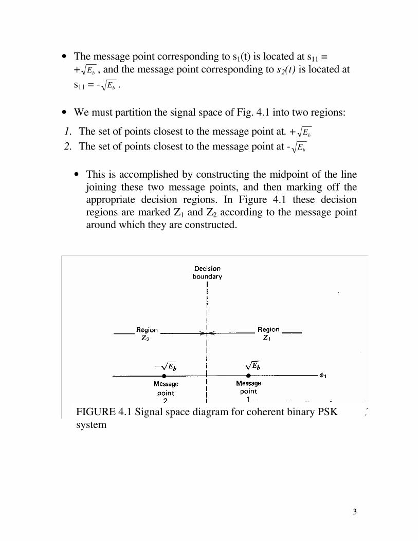
• The message point corresponding to s1(t) is located at s11 =
+ bE , and the message point corresponding to s2(t) is located at
s11 = - bE .
• We must partition the signal space of Fig. 4.1 into two regions:
1. The set of points closest to the message point at. + bE
2. The set of points closest to the message point at - bE
• This is accomplished by constructing the midpoint of the line
joining these two message points, and then marking off the
appropriate decision regions. In Figure 4.1 these decision
regions are marked Z1 and Z2 according to the message point
around which they are constructed.
FIGURE 4.1 Signal space diagram for coherent binary PSK
system
Page 4
4
• The decision rule is now simply to guess signal s1(t) or
binary symbol 1 was transmitted if the received signal point
falls in region Z1, and
• Signal s2(t) or binary symbol 0 was transmitted if the
received signal point falls in region Z2. Two kinds of
erroneous decisions may, however, be made.
• Signal s2(t) is transmitted, but the noise is such that the
received signal point falls inside region Z1 and so the receiver
decides in favor of signal s1(t).
• Alternatively, signal s1(t) is transmitted, but the noise is such
that the received signal point falls inside region Z2 and so the
receiver decides in favor of signal s2(t).
• The average probability of symbol error for coherent binary
PSK equals
• To generate a binary PSK wave, the input binary sequence in
polar form with symbols 1 and 0 represented by constant
amplitude levels of + bE and - bE , respectively.
4.8
Page 5
5
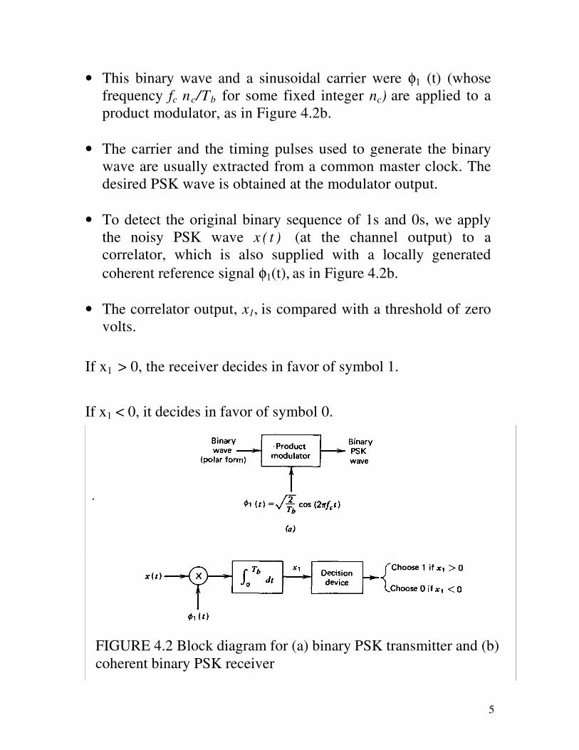
• This binary wave and a sinusoidal carrier were φ1 (t) (whose
frequency fc nc/Tb for some fixed integer nc) are applied to a
product modulator, as in Figure 4.2b.
• The carrier and the timing pulses used to generate the binary
wave are usually extracted from a common master clock. The
desired PSK wave is obtained at the modulator output.
• To detect the original binary sequence of 1s and 0s, we apply
the noisy PSK wave x ( t ) (at the channel output) to a
correlator, which is also supplied with a locally generated
coherent reference signal φ1(t), as in Figure 4.2b.
• The correlator output, x1, is compared with a threshold of zero
volts.
If x1 > 0, the receiver decides in favor of symbol 1.
If x1 < 0, it decides in favor of symbol 0.
FIGURE 4.2 Block diagram for (a) binary PSK transmitter and (b)
coherent binary PSK receiver
Page 6
6
4.2 Coherent Binary FSK
In a binary FSK system, symbols 1 and 0 are distinguished from
each other by transmitting one of two sinusoidal waves that differ
in frequency by a fixed amount. A typical pair of sinusoidal waves
is described by
where i = 1, 2, and Eb is the transmitted signal energy per bit, and
the transmitted frequency equals
Thus symbol 1 is represented by s1(t), and symbol 0 by s2(t).
From Eq 4.9 we observe directly that the signals s1(t) and s2(t) are
orthogonal, but not normalized to have unit energy. We therefore
deduce that the moss useful form for the set of orthonormal basis
functions is
where i = 1, 2. Correspondingly, the coefficient sij for i = 1, 2, and
j = 1, 2. is definers by
4.9
4.10
4.11
Page 7
7
Thus a coherent binary FSK system is characterized by having a
signal space that is two-dimensional (i.e., N = 2) with two message
points (i.e., M = 2), as in Figure 4-3. The two message points are
defined by the signal vectors:
FIGURE 4-3 Signal space diagram for coherent binary FSK
system.
4.12
Page 8
8
• Note that the distance between the two message points is equal
to b
E2 The observation vector x has two elements, x1 and x 2 ,
that are defined by, respectively
where x(t) is the received signal, the form of which depends on
which symbol was transmitted.
• Given that symbol 1 was transmitted, x(t) equals s1(t) + w(t),
where w(t) is the sample function of a white Gaussian noise
process of zero mean and power spectral density No/2.
• Symbol 0 was transmitted, x(t) equals s2(t) + w(t).
• The receiver decides in favor of symbol 1 if the received signal
point represented by the observation vector x falls inside region
Z1. This occurs when x1 > x2. If, on the other hand, we have x1
< x2, the received signal point falls inside region Z2, and the
receiver decides in favor of symbol 0. The decision boundary,
separating region Z1 from region Z2 , is defined by x1 = x2.
4.14
4.13
4.15
4.16
Page 9
9
The average probability of symbol error for coherent binary FSK is
• To generate a binary FSK signal, we may use the scheme shown
in Figure 4-4a.
• The input binary sequence is represented in its on–off form,
with symbol 1 represented by a constant amplitude of b
E volts
and symbol 0 represented by zero volts.
• By using an inverter in the lower channel in Figure 4-4a we in
effect make sure that when we have symbol 1 at the input, the
oscillator with frequency f1 in the upper channel is switched on
while the oscillator with frequency f2 in the lower channel is
switched off, with the result that frequency f1 is transmitted.
• Conversely, when we have symbol 0 at the input, the oscillator
in the upper channel is switched off, and the oscillator in the
lower channel is switched on, with the result that frequency f2 is
transmitted. The two frequencies f1 and f2 are chosen to equal
integer multiples of the bit rate 1 /Tb.
• In the transmitter of Figure 4-4a, we assume that the two
oscillators are synchronized, so that their outputs satisfy the
requirements of the two orthonormal basis functions φ1(t) and
φ2(t).
• Alternatively, we may use a single keyed (voltage-controlled)
oscillator. In either case, the frequency of the modulated wave
is shifted with a continuous phase, in accordance with the
input binary wave.
4.17
Page 10
10
• That is to say phase continuity is always maintained, including
the inter-bit switching times. We refer to this form of digital
modulation as continuous-phase frequency-shift keying
(CPFSK).
FIGURE 4-4 Block diagrams for (a) binary FSK transmitter, and
(b) coherent binary FSK receiver.
Page 11
11
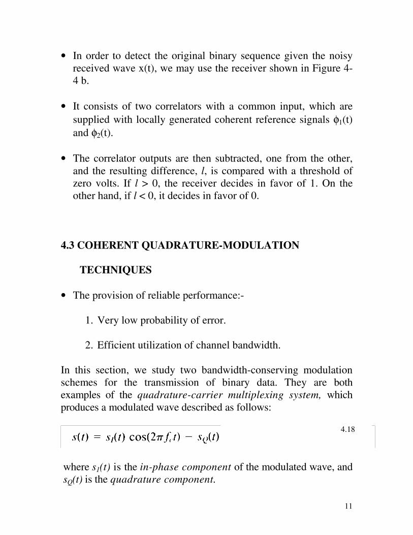
• In order to detect the original binary sequence given the noisy
received wave x(t), we may use the receiver shown in Figure 4-
4 b.
• It consists of two correlators with a common input, which are
supplied with locally generated coherent reference signals φ1(t)
and φ2(t).
• The correlator outputs are then subtracted, one from the other,
and the resulting difference, l, is compared with a threshold of
zero volts. If l > 0, the receiver decides in favor of 1. On the
other hand, if l < 0, it decides in favor of 0.
4.3 COHERENT QUADRATURE-MODULATION
TECHNIQUES
• The provision of reliable performance:-
1. Very low probability of error.
2. Efficient utilization of channel bandwidth.
In this section, we study two bandwidth-conserving modulation
schemes for the transmission of binary data. They are both
examples of the quadrature-carrier multiplexing system, which
produces a modulated wave described as follows:
where s1(t) is the in-phase component of the modulated wave, and
sQ(t) is the quadrature component.
4.18
Page 12
12
4.3.1 Quadriphase-shift Keying
• In quadriphase-shift keying (QPSK), the phase of the carrier
takes on one of four equally spaced values, such as π /4, 3π/4,
5π/4 and 7π/4 as shown by
• where i = 1, 2, 3, 4, and E is the transmitted signal energy per
symbol, T is the symbol duration, and the carrier frequency f.
equals nc /T for some fixed integer nc. Each possible value of the
phase corresponds to a unique pair of bits called a dibit.
• Thus, for example, we may choose the foregoing set of phase
values to represent the Gray encoded set of dibits: 10,00,01, and
11.
Using a well-known trigonometric identity, we may rewrite Eq.
4.19 in the equivalent form:
where i = 1, 2, 3, 4. Based on this representation, we can make the
following observations:
1. There are only two orthonormal basis functions, φ1(t) and φ2(t)
contained in the expansion of si(t). The appropriate forms for
φ1(t) and φ2(t) are defined by
4.19
4.20
Page 13
13
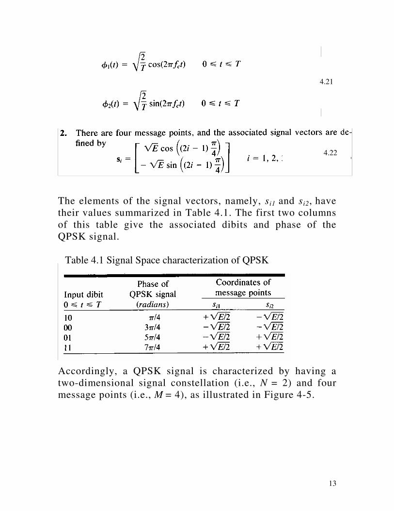
The elements of the signal vectors, namely, si1 and si2, have
their values summarized in Table 4.1. The first two columns
of this table give the associated dibits and phase of the
QPSK signal.
Accordingly, a QPSK signal is characterized by having a
two-dimensional signal constellation (i.e., N = 2) and four
message points (i.e., M = 4), as illustrated in Figure 4-5.
4.21
4.22
Table 4.1 Signal Space characterization of QPSK
Page 14
14
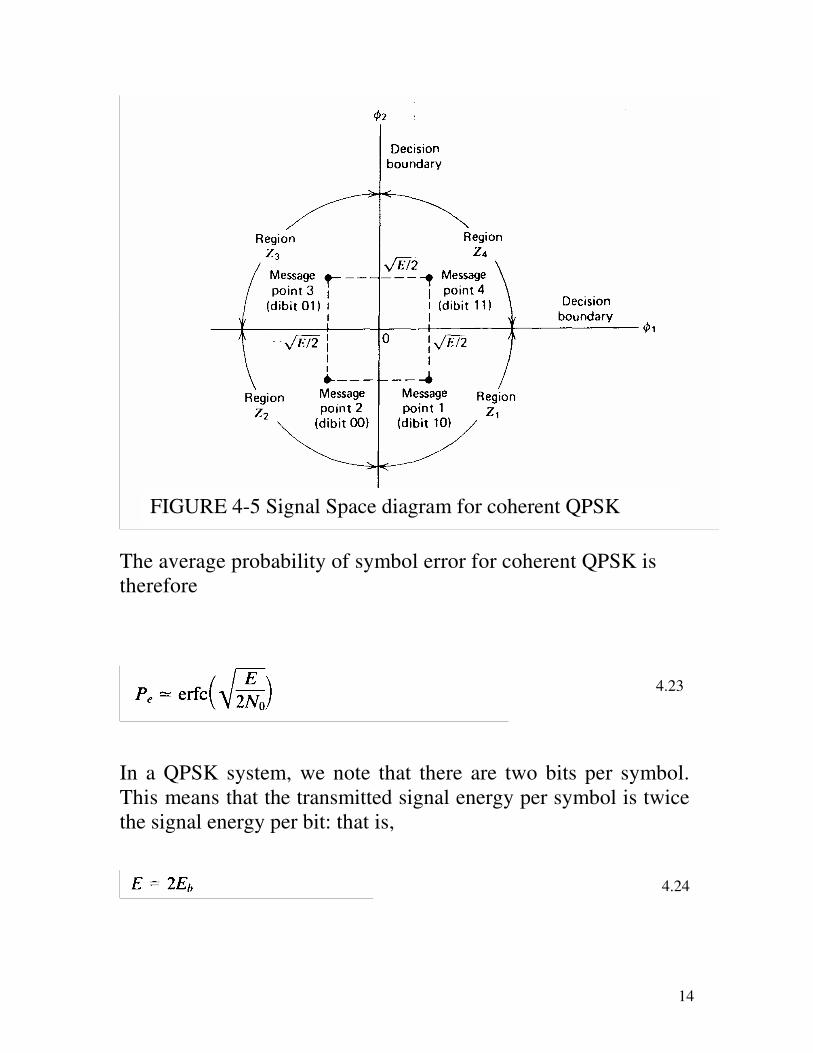
The average probability of symbol error for coherent QPSK is
therefore
In a QPSK system, we note that there are two bits per symbol.
This means that the transmitted signal energy per symbol is twice
the signal energy per bit: that is,
FIGURE 4-5 Signal Space diagram for coherent QPSK
system
4.23
4.24
Page 15
15
Thus, expressing the average probability of symbol error in terms
of the ratio Eb /No, we may write
• Figure 4-6a shows the block diagram of a typical QPSK
transmitter.
• The input binary sequence b(t) is represented in polar form, with
symbols 1 and 0 represented by b
E+ and b
E− volts,
respectively.
• This binary wave is divided by means of a demultiplexer into
two separate binary waves consisting of the odd- and even
numbered input bits.
• These two binary waves are denoted by b1(t) and b2(t). The
amplitudes of b 1(t) and b 2(t) equal si1 and si2 respectively
depending on the particular dibit that is being transmitted.
• The two binary waves b 1(t) and b2(t) are used to modulate a pair
of quadrature orthonormal basis functions: φ1(t) =
)2cos(/2 tfTc
π and φ1(t) = )2cos(/2 tfTc
π . The result is a pair
of binary PSK waves, which may detected independently due to
the orthogonality of φ1(t) and φ2(t).
• The QPSK receiver consists of a pair of correlators with a
common input and supplied with a locally generated pair of
coherent reference signals φ1(t) and φ2(t) as in Figure 4-6b. The
correlator outputs, x1 and x2, are each compared with a threshold
of zero volts.
4.25
Page 16
16
• If x1 > 0, a decision is made in favor of symbol 1 for the upper
or in-phase channel output, but if x1 < 0 a decision is made in
favor of symbol 0.
• If x2 > 0, a decision is made in favor of symbol 1 for the lower
or quadrature channel output, but if x2 < 0, a decision is made in
favor of symbol 0.
• Finally, these two binary sequences at the in-phase and
quadrature channel outputs are combined in a multiplexer to
reproduce the original binary sequence at the transmitter input
with the minimum probability of symbol error.
Page 17
17
FIGURE 4-6 Block diagrams for (a) QPSK transmitter, and (b)
QPSK receiver.
Page 18
18
4.4 NONCOHERENT BINARY MODULATION
TECHNIQUES
4.4.1 Noncoherent Orthogonal Modulation
• Consider a binary signaling scheme that involves the use of two
orthogonal signals s1(t) and s2(t), which have equal energy.
• During the interval 0 ≤ t ≤ T, one of these two signals is sent
over an imperfect channel that shifts the carrier phase by an
unknown amount.
• Let g1(t) and g2(t) denote the phase-shifted versions of s1(t) and
s2(t), respectively.
• It is assumed that the signals g1(t) and g2(t) remain orthogonal
and of equal energy, regardless of the unknown carrier phase. We
refer to such a signaling scheme as noncoherent orthogonal
modulation.
The channel also introduces an additive white Gaussian noise W(t)
of zero mean and power spectral density No/2. We may thus
express the received signal x(t) as
The requirement is to use x(t) to discriminate between s1(t) and
s2(t), regardless of the carrier phase.
4.26
Page 19
19
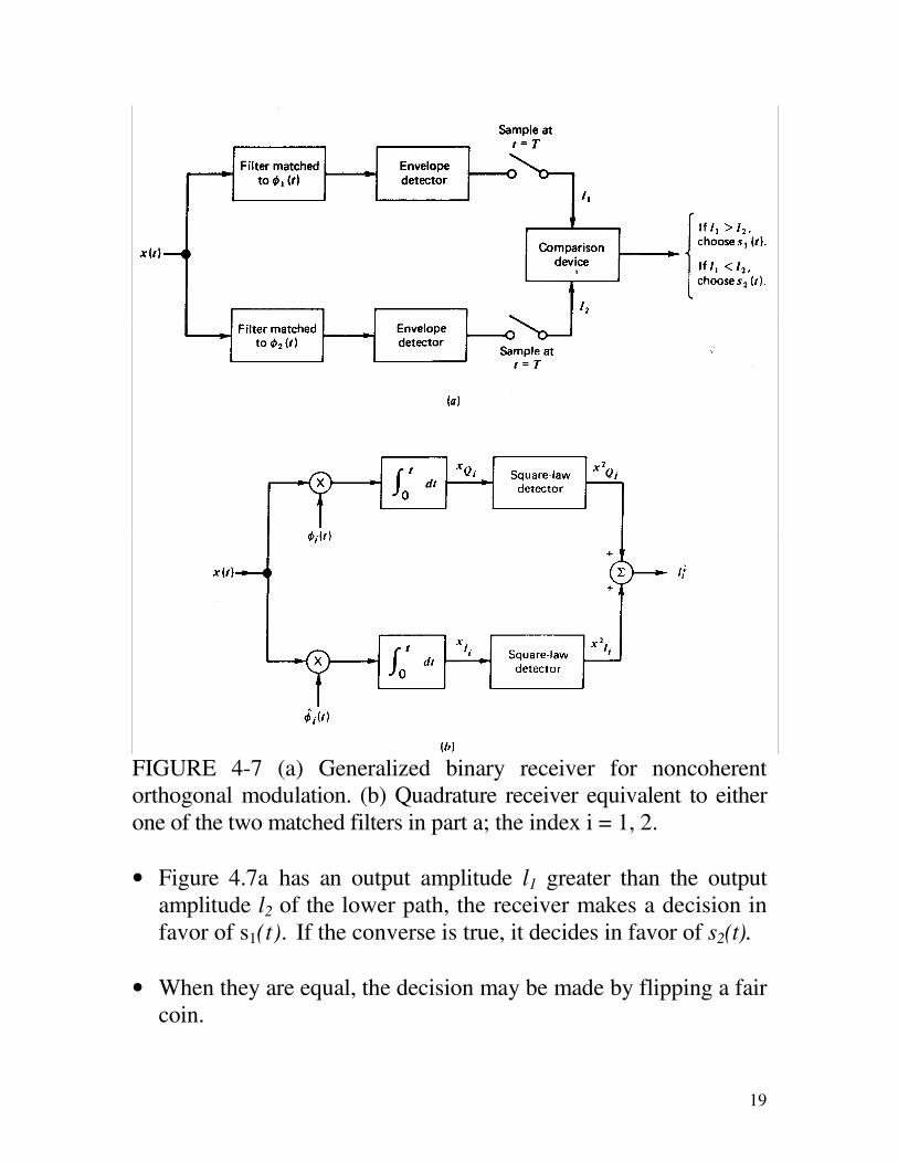
FIGURE 4-7 (a) Generalized binary receiver for noncoherent
orthogonal modulation. (b) Quadrature receiver equivalent to either
one of the two matched filters in part a; the index i = 1, 2.
• Figure 4.7a has an output amplitude l1 greater than the output
amplitude l2 of the lower path, the receiver makes a decision in
favor of s1(t). If the converse is true, it decides in favor of s2(t).
• When they are equal, the decision may be made by flipping a fair
coin.
Page 20
20
• In any event, a decision error occurs when the matched filter that
rejects signal component of the received signal x(t) has a larger
output amplitude (due to noise alone) than the matched filter
that passes it.
• The quadrature receiver is shown in Figure 4-7b. In the upper
path, called the in-phase path, the received signal x(t) is
correlated against the basis function φi(t), representing a scaled
version of the transmitted signal s1(t) or s2(t) with zero carrier
phase.
• In the lower path, called the quadrature path, on the other
hand, x(t) is correlated against another basis function ^
)(ti
φ representing the version of φi(t), that results from shifting the
carrier phase by -90°. Naturally, φi(t), and ^
)(ti
φ are orthogonal to
each other.
The average probability error for the noncoherent receiver is given
as
−=
oe
N
EP
2exp
2
1 (4.27)
4.4.2 Noncoherent Binary FSK
In the binary FSK case, the transmitted signal is defined by
(4.28)
Page 21
21
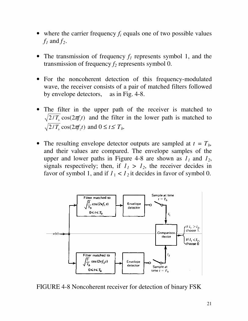
• where the carrier frequency fi equals one of two possible values
f1 and f2 .
• The transmission of frequency f1 represents symbol 1, and the
transmission of frequency f2 represents symbol 0.
• For the noncoherent detection of this frequency-modulated
wave, the receiver consists of a pair of matched filters followed
by envelope detectors, as in Fig. 4-8.
• The filter in the upper path of the receiver is matched to
)2cos(/21tfT
bπ and the filter in the lower path is matched to
)2cos(/22tfT
bπ and 0 ≤ t≤ Tb.
• The resulting envelope detector outputs are sampled at t = Tb, and their values are compared. The envelope samples of the
upper and lower paths in Figure 4-8 are shown as 11 and 12,
signals respectively; then, if 11 > 12, the receiver decides in
favor of symbol 1, and if 11 < 12 it decides in favor of symbol 0.
FIGURE 4-8 Noncoherent receiver for detection of binary FSK
Page 22
22
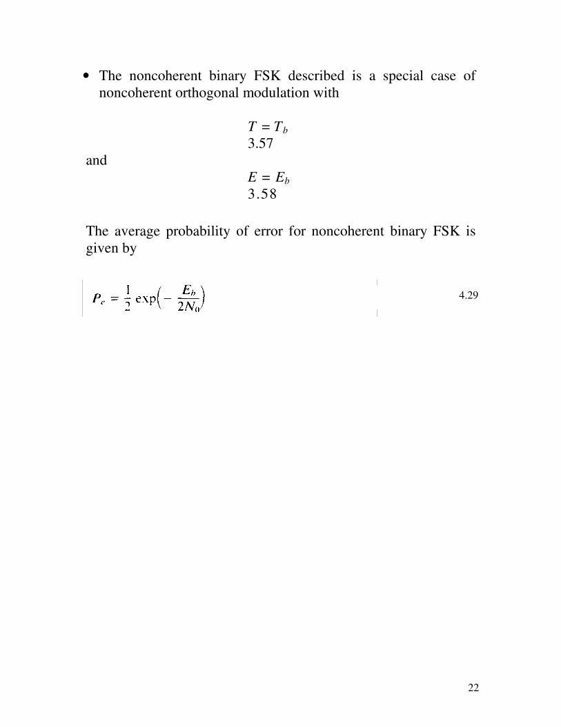
• The noncoherent binary FSK described is a special case of
noncoherent orthogonal modulation with
T = Tb
3.57
and
E = Eb
3.58
The average probability of error for noncoherent binary FSK is
given by
4.29
Page 23
23
3.5.3 Differential Phase-shift Keying
FIGURE 4-9 Block diagrams for (a) DPSK transmitter, and (b)
DPSK receiver.
• The transmitted DPSK signal equals )2cos(2/ tfTEcbb
π for 0 ≤ t
≤ Tb, where Tb is the bit duration and Eb is the signal energy per
bit.
• Let s1(t) denote the transmitted DPSK signal for 0≤ t≤ 2Tb for
the case when we have binary symbol 1 at the transmitter input
for the second part of this interval, namely, Tb ≤ t ≤ 2Tb.
• The transmission of 1 leaves the carrier phase unchanged, and
so we define s1(t) as
Page 24
24
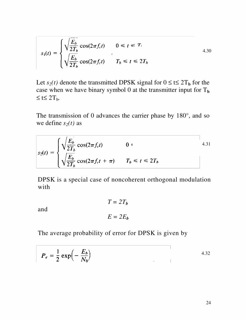
Let s2(t) denote the transmitted DPSK signal for 0 ≤ t≤ 2Tb for the
case when we have binary symbol 0 at the transmitter input for Tb
≤ t≤ 2Tb.
The transmission of 0 advances the carrier phase by 180°, and so
we define s2(t) as
DPSK is a special case of noncoherent orthogonal modulation
with
T = 2Tb
and
E = 2Eb
The average probability of error for DPSK is given by
4.30
4.32
4.31
Page 25
25
FIGURE 4-10 Comparison of the noise performances of
different PSK and FSK schemes.
Page 26
26
Summary:
1. The error rates for all the systems decrease monotonically
with increasing values of Eb/No .
2. For any value of Eb/No, coherent PSK produces a smaller
error rate than any of the other systems. Indeed, it may be
shown that in the case of systems restricted to one-bit
decoding, perturbed by additive white Gaussian noise,
coherent PSK system is the optimum system for transmitting
binary data in the sense that it achieves the minimum
probability of symbol error for a given value of Eb/No .
3. Coherent PSK and DPSK require an Eb/No that is 3 dB less
than the corresponding values for conventional coherent FSK
and noncoherent FSK, respectively, to realize the same error
rate.
4. At high values of Eb/No , DPSK and noncoherent FSK
perform almost as well (to within about 1 dB) as coherent
PSK and conventional coherent FSK, respectively, for the
same bit rate and signal energy per bit.
5. In QPSK two orthogonal carriers )2cos(/2 tfTc
π and
)2sin(/2 tfTc
π are used, where the carrier frequency fc is an
integral multiple of the symbol rate 1/T, with the result that
two independent bit streams can he transmitted and
subsequently detected in the receiver. At high values of
Eb/No coherently detected binary PSK and QPSK have about
the same error rate performance for the same value of Eb/No.


![All-Optical Signal Processing for High Spectral Efficiency ... · SE, the large bandwidth and multilevel modulation formats [5]. Coherent optical systems using multilevel modulation](https://static.documents.pub/doc/80x56/5ecf8c9b3dff6463180c0404/all-optical-signal-processing-for-high-spectral-efficiency-se-the-large-bandwidth.jpg)


