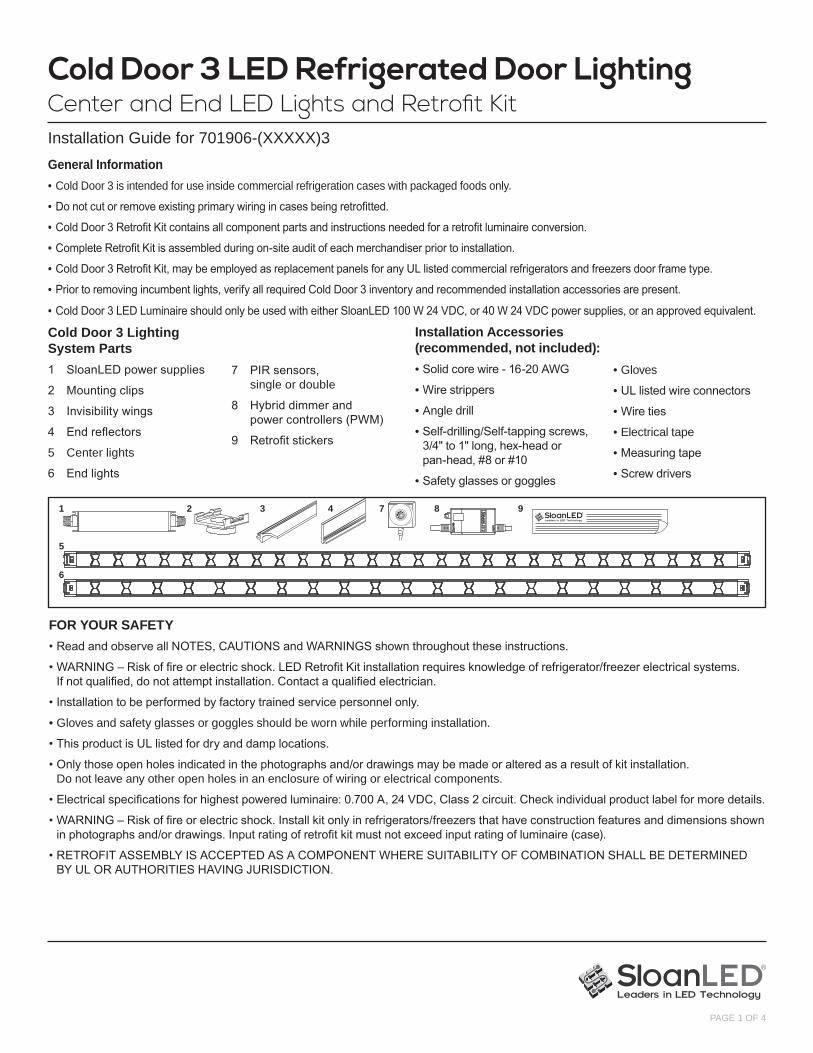
Cold Door 3 LED Refrigerated Door Lighting Center and End LED Lights and Retrofit Kit Installation Guide for 701906-(XXXXX)3 PAGE 1 OF 4 General Information • Cold Door 3 is intended for use inside commercial refrigeration cases with packaged foods only. • Do not cut or remove existing primary wiring in cases being retrofitted. • Cold Door 3 Retrofit Kit contains all component parts and instructions needed for a retrofit luminaire conversion. • Complete Retrofit Kit is assembled during on-site audit of each merchandiser prior to installation. • Cold Door 3 Retrofit Kit, may be employed as replacement panels for any UL listed commercial refrigerators and freezers door frame type. • Prior to removing incumbent lights, verify all required Cold Door 3 inventory and recommended installation accessories are present. • Cold Door 3 LED Luminaire should only be used with either SloanLED 100 W 24 VDC, or 40 W 24 VDC power supplies, or an approved equivalent. FOR YOUR SAFETY • Read and observe all NOTES, CAUTIONS and WARNINGS shown throughout these instructions. • WARNING – Risk of fire or electric shock. LED Retrofit Kit installation requires knowledge of refrigerator/freezer electrical systems. If not qualified, do not attempt installation. Contact a qualified electrician. • Installation to be performed by factory trained service personnel only. • Gloves and safety glasses or goggles should be worn while performing installation. • This product is UL listed for dry and damp locations. • Only those open holes indicated in the photographs and/or drawings may be made or altered as a result of kit installation. Do not leave any other open holes in an enclosure of wiring or electrical components. • Electrical specifications for highest powered luminaire: 0.700 A, 24 VDC, Class 2 circuit. Check individual product label for more details. • WARNING – Risk of fire or electric shock. Install kit only in refrigerators/freezers that have construction features and dimensions shown in photographs and/or drawings. Input rating of retrofit kit must not exceed input rating of luminaire (case). • RETROFIT ASSEMBLY IS ACCEPTED AS A COMPONENT WHERE SUITABILITY OF COMBINATION SHALL BE DETERMINED BY UL OR AUTHORITIES HAVING JURISDICTION. Installation Accessories (recommended, not included): • Solid core wire - 16-20 AWG • Wire strippers • Angle drill • Self-drilling/Self-tapping screws, 3/4" to 1" long, hex-head or pan-head, #8 or #10 • Safety glasses or goggles • Gloves • UL listed wire connectors • Wire ties • Electrical tape • Measuring tape • Screw drivers Cold Door 3 Lighting System Parts 1 SloanLED power supplies 2 Mounting clips 3 Invisibility wings 4 End reflectors 5 Center lights 6 End lights 7 PIR sensors, single or double 8 Hybrid dimmer and power controllers (PWM) 9 Retrofit stickers 1 2 3 4 7 8 9 5 6
Transcript
Cold Door 3 LED Refrigerated Door LightingCenter and End LED Lights and Retrofit KitInstallation Guide for 701906-(XXXXX)3
PAGE 1 OF 4
General Information• Cold Door 3 is intended for use inside commercial refrigeration cases with packaged foods only.
• Do not cut or remove existing primary wiring in cases being retrofitted.
• Cold Door 3 Retrofit Kit contains all component parts and instructions needed for a retrofit luminaire conversion.
• Complete Retrofit Kit is assembled during on-site audit of each merchandiser prior to installation.
• Cold Door 3 Retrofit Kit, may be employed as replacement panels for any UL listed commercial refrigerators and freezers door frame type.
• Prior to removing incumbent lights, verify all required Cold Door 3 inventory and recommended installation accessories are present.
• Cold Door 3 LED Luminaire should only be used with either SloanLED 100 W 24 VDC, or 40 W 24 VDC power supplies, or an approved equivalent.
FOR YOUR SAFETY• Read and observe all NOTES, CAUTIONS and WARNINGS shown throughout these instructions.
• WARNING – Risk of fire or electric shock. LED Retrofit Kit installation requires knowledge of refrigerator/freezer electrical systems. If not qualified, do not attempt installation. Contact a qualified electrician.
• Installation to be performed by factory trained service personnel only.
• Gloves and safety glasses or goggles should be worn while performing installation.
• This product is UL listed for dry and damp locations.
• Only those open holes indicated in the photographs and/or drawings may be made or altered as a result of kit installation. Do not leave any other open holes in an enclosure of wiring or electrical components.
• Electrical specifications for highest powered luminaire: 0.700 A, 24 VDC, Class 2 circuit. Check individual product label for more details.
• WARNING – Risk of fire or electric shock. Install kit only in refrigerators/freezers that have construction features and dimensions shown in photographs and/or drawings. Input rating of retrofit kit must not exceed input rating of luminaire (case).
• RETROFIT ASSEMBLY IS ACCEPTED AS A COMPONENT WHERE SUITABILITY OF COMBINATION SHALL BE DETERMINED BY UL OR AUTHORITIES HAVING JURISDICTION.
• Self-drilling/Self-tapping screws, 3/4" to 1" long, hex-head or pan-head, #8 or #10
• Safety glasses or goggles
• Gloves
• UL listed wire connectors
• Wire ties
• Electrical tape
• Measuring tape
• Screw drivers
Cold Door 3 Lighting System Parts1 SloanLED power supplies
2 Mounting clips
3 Invisibility wings
4 End reflectors
5 Center lights
6 End lights
7 PIR sensors, single or double
8 Hybrid dimmer and power controllers (PWM)
9 Retrofit stickers
1 2 3 4 7 8 9
5
6
Cold Door 3 LED Refrigerated Door LightingCenter and End LED Lights and Retrofit KitInstallation Guide for 701906-(XXXXX)3
PAGE 2 OF 4
Only one power supply is needed for each frame up to 5-doors regardless of length. See Power Supply Selection Guide to ensure you have most energy efficient solution for frame being retrofitted.
Power Supply and Dimming/Controllers
Choose one former ballast location for power supply to be installed in. Mount power supply with two self-drilling/self-tapping screws through tabs in both end caps.
NOTE: One power controller or hybrid dimming and power controller required per power supply.
Power Supply Selection Guide (Class 2 power supply)
Doors per frameDoor Length - ECO Line 5 4 3 2 15' ECO Line Cold Door 3 51.0 40.9 30.8 20.7 10.66' ECO Line Cold Door 3 53.8 43.7 33.6 23.5 13.47' ECO Line Cold Door 3 53.8 43.7 33.6 23.5 13.4
Total power (W, DC) Doors per frameDoor length - Performance Line 5 4 3 2 14' Performance Line Cold Door 3 59.2 48.0 36.8 25.6 14.45' Performance Line Cold Door 3 74.4 60.5 46.6 32.7 18.86' Performance Line Cold Door 3 86.0 69.7 53.4 37.1 20.87' Performance Line Cold Door 3 92.2 74.8 57.4 40.0 22.6
Color Guide Use40 W 24 VDC (P/N: 410175)100 W 24 VDC (P/N: 701895-24W)
Preparation for Installation:
WARNING – Risk of electric shock. Locate main circuit breaker panel, de-energize, and perform lock-out/tag-out prior to retrofitting case. All primary wiring must be done by a licensed electrician.
1. Remove existing lighting system, including: bulbs, ballasts, reflectors, clips, LED lights, power supplies, etc. Ballasts and power supplies are normally located in mullions, raceways, or on top of cases.
Wiring Diagram – With controlsTypical 5-Door installation with Motion Sensor and Dimming Control, one (1) power supply, four (4) Center lights, and two (2) End lights
Cen
ter l
ight
Cen
ter l
ight
Motion sensor
Dimming controller
Cen
ter l
ight
Cen
ter l
ight
End
light
End
light
Power supply
Installation:Wiring Diagram – No controlsTypical 5-Door installation with one (1) power supply, four (4) center lights, and two (2) end lights
Cen
ter l
ight
Cen
ter l
ight
Cen
ter l
ight
Cen
ter l
ight
End
light
End
light
Power supplyCorrect
Correct
Cen
ter l
ight
Cen
ter l
ight
Cen
ter l
ight
Cen
ter l
ight
End
light
End
light
Power supplyIncorrect
Cen
ter l
ight
Cen
ter l
ight
Cen
ter l
ight
Cen
ter l
ight
End
light
End
light
Power supplyIncorrect
WARNING: Incorrect wiring as shown below may damage product.
Cold Door 3 LED Refrigerated Door LightingCenter and End LED Lights and Retrofit KitInstallation Guide for 701906-(XXXXX)3
PAGE 3 OF 4
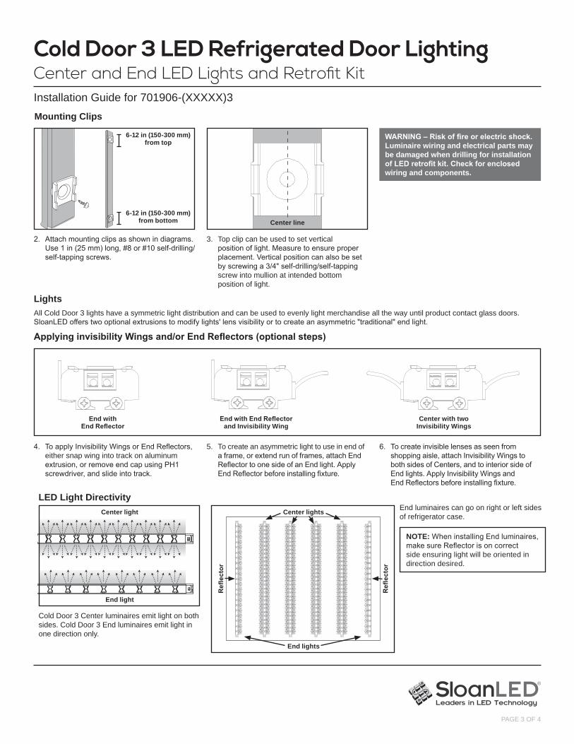
Applying invisibility Wings and/or End Reflectors (optional steps)
4. To apply Invisibility Wings or End Reflectors, either snap wing into track on aluminum extrusion, or remove end cap using PH1 screwdriver, and slide into track.
5. To create an asymmetric light to use in end of a frame, or extend run of frames, attach End Reflector to one side of an End light. Apply End Reflector before installing fixture.
6. To create invisible lenses as seen from shopping aisle, attach Invisibility Wings to both sides of Centers, and to interior side of End lights. Apply Invisibility Wings and End Reflectors before installing fixture.
End with End Reflector and Invisibility Wing
End with End Reflector
Center with two Invisibility Wings
LightsAll Cold Door 3 lights have a symmetric light distribution and can be used to evenly light merchandise all the way until product contact glass doors. SloanLED offers two optional extrusions to modify lights' lens visibility or to create an asymmetric "traditional" end light.
Mounting Clips
WARNING – Risk of fire or electric shock. Luminaire wiring and electrical parts may be damaged when drilling for installation of LED retrofit kit. Check for enclosed wiring and components.
2. Attach mounting clips as shown in diagrams. Use 1 in (25 mm) long, #8 or #10 self-drilling/self-tapping screws.
6-12 in (150-300 mm) from top
6-12 in (150-300 mm) from bottom
3. Top clip can be used to set vertical position of light. Measure to ensure proper placement. Vertical position can also be set by screwing a 3/4" self-drilling/self-tapping screw into mullion at intended bottom position of light.
Center line
NOTE: When installing End luminaires, make sure Reflector is on correct side ensuring light will be oriented in direction desired.
Cold Door 3 Center luminaires emit light on both sides. Cold Door 3 End luminaires emit light in one direction only.
End luminaires can go on right or left sides of refrigerator case.
LED Light DirectivityCenter light Center lights
End lights
Refl
ecto
r
Refl
ecto
r
End light
Cold Door 3 LED Refrigerated Door LightingCenter and End LED Lights and Retrofit KitInstallation Guide for 701906-(XXXXX)3
PAGE 4 OF 4
Customer service and technical support888.747.4LED (888.747.4533)SloanLED.com • [email protected]
Europe: Customer service and technical support+31 88 12 44 900SloanLED.com • [email protected]
P/N 402141 Rev E 2017-11-15
9. Prior to closing all mullions and raceways, re-energize system and verify performance.
Test System
Close Case and Clean UpReplace all covers and guards removed during preparation and installation. Affix Retrofit Sticker next to each power switch on refrigerator or freezer case.
Selectable Duty Cycle output via SW 1 and SW 2 (Brightness level when shopper in area).
Selectable Duty Cycle output via SW 3 and SW 4 (brightness level when no shoppers in area). Percentage values represent brightness and power of maximum system load.
Dimming Controller SettingsMerchandising Setting (Brightness) Dim Mode
Brightness Level SW 1 SW 2 Percent of
Full BrightnessSW 3 On
SW 4 On
SW 3 Off
SW 4 On
SW 3 On
SW 4 Off
Energy Saver ON OFF 50% 15% 0% 0%
Standard OFF ON 75% 30% 7.5% 0%
MerchandiserMax ON ON 100% 55% 25% 15%
Factory setting is 100% Brightness, 0% Dimming.
Dimming Controller P/N 701890-PWR
Removal Instructions
1. De-energize system as outlined in Preparation for Install section on page two of this installation guide and undo electrical connections to LED lights.
2. For alternate mounting method, using a flat tip screwdriver, insert tip between mounting clip and LED light to pry from clip edge.
3. Repeat process for remaining lights. Make sure to continually support LED lights with a free hand during removal.
4. Open mullions or raceway, remove power supplies.
5. Cap or remove all primary wires.
NSF/ANSI 2 US patents and foreign patents pending
8. Snap luminaire into mounting clips. See Mounting Clip section to fix vertical position of lights. To remove luminaire, insert flat blade screwdriver into slot on mounting clip, and carefully pry luminaire from clip.
Light Installation
WARNING – To prevent wiring damage or abrasion, do not expose wiring to edges of sheet metal or other sharp objects.
7. Only 16 - 20 AWG (0.5 mm2 - 1.5 mm2) solid core wires should be used for insertion into end caps of Cold Door 3 terminal blocks. Run secondary wire from power supply through holes in door frame mullions to luminaire. Use end cap as strip length guide, and strip wires 7-9 mm (0.28-0.35"). Push wires through holes in end caps until engaged in terminal block. Cold Door 3 is polarity insensitive, and cannot be daisy chained in a series. Refer to appropriate wiring diagram.