102


First edition: 2000, 1000 copies
Author: Seamus Collins
Illustrations: Seamus Collins; SKAT
Published by: SKAT, Swiss Centre for Development Cooperationin Technology and Management
Copyright: © SKAT, 2000
Comments: Please send any comments concerning this publication to:
SKATVadianstrasse 42CH-9000 St.Gallen, Switzerland
Tel: +41 71 228 54 54Fax: +41 71 228 54 55e-mail: [email protected]
Photos: Enges, Maputo
Printed by: Niedermann Druck, St.Gallen, Switzerland
ISBN: 3-908001-97-8
Impressum
ContextAccess to adequate water, sanitation, drainage and solid waste disposal are four in-ter-related basic needs which impact significantly on socio-economic development andquality of life. The number of people around the world who still do not have accessto these basic facilities, despite enormous global effort over more than two decades,provides sufficient evidence that conventional approaches and solutions alone areunable to make a sufficient dent in the service backlog which still exists. Numerousinitiatives are ongoing at different levels to improve strategies, technologies, institu-tional arrangements, socio-cultural anchorage, and cost effectiveness, all to enhanceefficiency and, eventually, to have an impact on the sector's goals. In addition, theever-increasing scarcity of water brings policymakers together to find solutions to thechallenge of water resource management. This series of manuals is intended as acontribution to these efforts.
BackgroundThe decision to produce this series of manual was prompted by the positive experi-ence gained with a practical manual based on the experience of Helvetas (a SwissNGO) during the 1970s in Cameroon, which has become outdated with the pas-sage of time. SDC (the Swiss Agency for Development and Co-operation) supportedSKAT's initiative to produce this series, working with professionals with longstandingpractical experience in the implementation of rural water supply projects. Lessonslearnt during the workshops held by AGUASAN (an interdisciplinary working groupof water and sanitation professionals from Swiss development and research organi-sations) over the last 14 years have been included where appropriate. In particular,there is an emphasis on documenting and illustrating practical experiences from allregions of the world.
The ManualsAs can be seen from the table below, this series of manuals is primarily aimed atproject mangers, engineers and technicians. However, given the wide range of sub-jects covered, it is also an important working tool for all actors in the sector, rang-ing from those involved with policy development to those constructing systems atvillage level. The series has a clear focus on water supply in rural settings. It pro-poses technologies with due consideration for socio-cultural, economic, institutionaland regulatory requirements. This approach is in keeping with the SDC water andsanitation policy, emphasising the balanced development approach leading to sus-tainable programmes and projects.
It should be noted that the present series deals almost exclusively with water sup-ply. The importance of sanitation is however clearly established in Volume 1, whichdeals predominantly with the software aspects necessary to achieve an impact. Itincludes some proposals for optional tools, approaches and institutional arrangementsand is intended as an overall introduction to the other, more technical, volumes ofthe series.
Some final commentsThe water and sanitation sector is constantly evolving. We would welcome any que-ries, comments or suggestions you might have. Your feedback will be made avail-able to other interested users of the manuals.
Finally, we hope that these manuals will be useful for the practitioner in the fieldas well as for the planner in the office. If the series can be a contribution to provid-ing water to more people in need on a sustainable basis, we will have achievedour goal.
The production of this series has only been possible through the continuous sup-port of colleagues from all over the world. Our sincere thanks to all of them.
Armon Hartmann Karl WehrleHead of Water & Infrastructure Division Head of Water & Construction DivisionSwiss Agency for Development Co-operation SKAT
Foreword

Acknowledgments
For advice and assistance, technical or otherwise, in the completion of this manual,I would like to thank the following:
Karl Wehrle, Franz Gähwiler and Erich Baumann from SKAT;
Albert Bürgi (Zürich) and Stuart Bland (Cabo Delgado, Mozambique) from Helvetas;
and my wife Karina for her support throughout.
It goes without saying that any errors which remain in the text are my own.

Contents
i
Contents
1. Introduction ...................................................................................... 1
2. Rural water supply — The non-technical aspects ............................. 3
2.1 Introduction ..............................................................................................................3
2.2 Health and hygiene education in relation to water supply .................................32.2.1 Water-related diseases ............................................................................................... 32.2.2 Hygiene Education and Water Supply ........................................................................ 4
2.3 The management of construction, operation and maintenance .........................6
2.4 Economic implications and impact ...................................................................... 10
2.5 Social, cultural and environmental aspects ........................................................ 11
2.6 Preconditions for successful water supply activities .........................................13
2.7 Conclusions .............................................................................................................14
3. Technical aspects of rural water supply ......................................... 15
3.1 Introduction ............................................................................................................15
3.2 The occurrence of groundwater............................................................................153.2.1 The Hydrological Cycle............................................................................................. 153.2.2 Types of aquifer ....................................................................................................... 16
3.3 Water quantity ........................................................................................................ 173.3.1 Supply and demand ................................................................................................. 173.3.2 Exploiting and managing the water resource .......................................................... 18
3.4 Water quality ..........................................................................................................193.4.1 Drinking water quality and monitoring ..................................................................... 193.4.2 Disinfection .............................................................................................................. 20
3.5 Technical requirements for construction, operation and maintenance ............ 21
4. Options for water supply technologies........................................... 23
4.1 Introduction ............................................................................................................23
4.2 Spring catchments .................................................................................................23
4.3 Bored wells .............................................................................................................244.3.1 Driven tube well ....................................................................................................... 244.3.2 Bored tube well ........................................................................................................ 244.3.3 Jetted tube well ....................................................................................................... 244.3.4 Mechanically drilled borehole ................................................................................... 254.3.5 Comparison of methods .......................................................................................... 26
5. Principles of hand-dug wells .......................................................... 29
5.1 The technology of hand-dug wells .......................................................................295.1.1 Introduction .............................................................................................................. 295.1.2 Soil conditions .......................................................................................................... 295.1.3 Well diameter ........................................................................................................... 295.1.4 Depth of well in aquifer ........................................................................................... 30

Hand-dug shallow wells
ii
5.2 Elements of a hand-dug well ................................................................................305.2.1 Introduction .............................................................................................................. 305.2.2 Well Head ................................................................................................................ 305.2.3 Shaft ......................................................................................................................... 315.2.4 Intake ....................................................................................................................... 31
5.3 Advantages and disadvantages of hand-dug wells ............................................ 32
6. Information collection .................................................................... 35
6.1 The information gathering process ......................................................................35
6.2 Technical site investigation ................................................................................... 376.2.1 Testing methods and equipment ............................................................................. 376.2.2 Test procedure ......................................................................................................... 386.2.3 Interpretation of test results .................................................................................... 38
6.3 Guidelines for the siting of a waterpoint ............................................................39
6.4 Making the decision ...............................................................................................41
7. The lining of hand-dug wells .......................................................... 43
7.1 Lining options .........................................................................................................43
7.2 Concrete for use in well lining ..............................................................................44
7.3 Advantages and disadvantages of using precast concrete lining elements .... 45
7.4 Precast reinforced concrete rings ......................................................................... 45
8. Hand-dug well construction procedures — General ....................... 47
8.1 Introduction ............................................................................................................47
8.2 Equipment ...............................................................................................................47
8.3 Intake Construction ................................................................................................47
8.4 Site layout ...............................................................................................................48
8.5 Safety precautions .................................................................................................49
9. Examples of construction sequences ............................................. 51
9.1 Introduction ............................................................................................................51
9.2 Location of excavation ...........................................................................................51
9.3 Cast in-situ concrete lining with prefabricated caisson intake .........................52
9.4 Concrete lining with built in-situ intake .............................................................. 54
9.5 Prefabricated concrete lining rings .......................................................................55
10. Concluding works ........................................................................... 59
10.1 Finishing off above ground ................................................................................... 59
10.2 Disinfection of the completed well ......................................................................59
10.3 Well apron ...............................................................................................................60
10.4 Fencing ....................................................................................................................61
10.5 Laundry slab ...........................................................................................................61
11. Precast concrete elements for hand-dug wells .............................. 63
11.1 Introduction ............................................................................................................63
11.2 Formwork and equipment .....................................................................................64

Contents
iii
11.3 Prefabricated concrete lining rings .......................................................................6411.3.1 Standard ring ............................................................................................................ 6411.3.2 Filter ring .................................................................................................................. 6611.3.3 Cutting (Leading) ring ............................................................................................... 6611.3.4 Rings with rebate..................................................................................................... 6711.3.5 Extension (telescoping) rings ................................................................................... 67
11.4 Other precast concrete elements ......................................................................... 6811.4.1 Well cover slab......................................................................................................... 6811.4.2 Inspection cover....................................................................................................... 6811.4.3 Bottom slabs ............................................................................................................ 69
12. Common problems .......................................................................... 71
12.1 Introduction ............................................................................................................71
12.2 Excavation in loose soils .......................................................................................71
12.3 Loss of vertical alignment .....................................................................................72
12.4 Arrested descent of lining rings ............................................................................72
13. Low-yield wells................................................................................ 73
13.1 New wells ...............................................................................................................73
13.2 Improving the yield of existing wells ................................................................... 7413.2.1 Introduction ............................................................................................................... 7413.2.2 Horizontal extension of well ..................................................................................... 7413.2.3 Vertical extension of well .......................................................................................... 74
14. Management, operation and maintenance ..................................... 77
14.1 Introduction ............................................................................................................77
14.2 Hygiene and health considerations ......................................................................78
14.3 Structural maintenance .........................................................................................78
14.4 Maintenance of water-lifting devices ...................................................................79
Appendix 1. References and Further Reading ...................................... 81
Appendix 2. Forms for use in Trial Borehole and Yield Test .................. 83
Appendix 3. Drawings for Concrete Components ................................ 87

Hand-dug shallow wells
iv

1
Introduction
This Manual, Volume 5 in the SKAT series on RuralWater Supply, deals with the planning, construction,management, operation and maintenance of hand-dug wells for water supply to communities in theSouth. It is intended to be used by planners, engi-neers and technicians in the Water Sector, with theaim of facilitating the decision on the type of tech-nology to use in a given situation and, whererelevant, to outline the implementation of that tech-nology. It is hoped that the manual will also be usefulto those involved in village liaison work, in givingan idea of the technical aspects related to improv-ing village water supplies.
Because of its essentially organic and dynamicnature, the process of development in any givengeographical or sectoral area is heavily dependenton existing conditions. As a result, the process doesnot have a uniform pace throughout the world, oreven within one country. A cursory glance at theWater Sectors of different countries will reveal widelyvarying degrees of institutional, policy and humanresource development, together with a range of tech-nologies to cater for the different situations (social,cultural, economic and technical) encountered. It isbeyond the scope of this manual to try to cover allpossible permutations of institutional and technicalvariations. However, an important aspect of themanual is that, while the focus is primarily techni-cal, attention is given to the many non-technicalfactors which must be considered in any watersupply system. It is hoped that the overall pictureof the water supply process is conveyed, and thatthe need for consideration of both technical and non-technical factors, at all stages of the process, isestablished. With regard to the managementaspects of the water supply process, the reader isreferred to Volume 1 of this series of Manuals –Project management.
At the time of writing, 1.3 billion people in develop-ing countries do not have access to safe water,while over 2.5 billion do not have access to sanita-tion. Two water-borne diseases, diarrhoea anddysentery, account for an estimated 20% of the totalburden of disease in developing countries. Pollutedwater is the cause of almost 2 billion cases ofdiarrhoea each year1 . Given the complex inter-relationships between the health, water and sanita-tion sectors, it is clear that any initiative confinedto only one sector will have a limited effect on theimprovement of the quality of life. Nevertheless, theavailability of cheap, easily-applied water supplytechnologies can make a significant contribution tothe development of solutions in a multi-disciplinaryapproach to the improvement of living standards inthe South.
Hand-dug wells provide a cheap, low-technologysolution to the challenges of rural water supply,in addition to affording an ideal opportunity for ahigh level of community participation during allphases of the water supply process (see, however,the note on safety precautions in Section 8.5).In areas which are geologically suited to the tech-nology, where local capacity-building is a priorityand where circumstances do not dictate the use offaster or more sophisticated methods, the construc-tion of hand-dug wells can be easily assimilatedby a relatively unsophisticated water sector, espe-cially in the technical sense. Hand-dug wells canprovide a viable alternative to unhygienic, unpro-tected sources while avoiding the capital andmaintenance costs associated with sophisticateddrilling programmes or reticulated pumped systems.A range of lining types and water lifting technolo-gies2 can be chosen to match the financial andmanagement capacity of the participants in thewater supply process.
1.Introduction
1 UNDP, Human Development Report 1998, p. 682 See Volume 7 in this series - Water Lifting

Hand-dug shallow wells
2
This manual concentrates on the construction andmaintenance of hand-dug wells with a diameter of1.0-1.5m. Wells of this type have been excavatedto depths in excess of 60m, sometimes using agreater diameter. Local conditions, in addition toconsiderations of safety and economy, will indicatethe average depth of hand-dug wells in a particulararea. Beyond a certain depth, the option of mechani-cally-drilled boreholes must be considered aspreferable in terms of safety, cost (both capital andmaintenance), and time.
In the case of hand-dug wells, as the name implies,excavation is done by hand and the well may belined using any one of a number of options asdescribed later in this manual. For the sake of brevityand accessibility, the manual deals more specificallywith the use of concrete lining, both reinforced andunreinforced, precast and cast in-situ. Local condi-tions, technical expertise, tradition and capacitiesmust be taken into account in any decision. Toassist in the decision with regard to the technologyto be adopted in any given situation, Chapters 2-5contain a series of checklists which can be usedduring the decision-making process. The manual isstructured around the process of providing water toa rural community, dealing at first with more gen-eral considerations before concentrating on thetechnology of hand-dug wells. The topics treated are:� the non-technical aspects of rural water supply,
including health, hygiene, management, institu-tions and economic, social and environmentalaspects;
� •the technical background, the water cycle,water quantity and quality;
� the options for the exploitation of drinking-watersources;
� principles of hand-dug wells;� site investigation;� practice and procedures in hand-dug well con-
struction;� management, operation and maintenance of
hand-dug wells
It will be noted that the more technical aspectsof well construction are sandwiched between chap-ters on the somewhat less tangible aspects of thewater supply process. Thus Chapter 2 deals withthe non-technical aspects of the process, whileChapter 14 highlights the important subject of man-agement, operation and maintenance. It is hopedthat this layout will serve to emphasise the fact that
water supply as an activity is not purely technicalin nature.
It is important to mention community participation.This phrase is used throughout the manual, thoughit is accepted that the concept may be interpretedvery differently by different people. In this manual,the phrase is used to imply the full and voluntaryparticipation of the community in all phases of thewater supply process, including the submission ofan initial request for the provision of such a supply.The institutional framework within which this par-ticipation may take place will vary widely fromcountry to country. It is clear that the situationdescribed above is the ideal rather than the realityin many cases. The community, for various reasons,may not participate to the extent of either its will-ingness or its ability. The water system may beimposed rather than requested. Nevertheless, wehave referred throughout the text to “communityparticipation” in the terms outlined above, in thebelief that, while many water supply systems arebuilt with a less-than-desirable degree ofcommunity involvement, those that are constructedwith the full participation of the end users consti-tute a more lasting contribution to the improvementof health and living conditions in the South. Theissue of community participation is treated in moredepth in the Manual on Management of WaterSupply Systems.

3
Rural Water Supply — The non-technical aspects
2.Rural water supply —The non-technical aspects
2.1 Introduction
At its most basic level, the physical activity ofproviding improved water supply systems in ruralcommunities is undertaken with a view to contrib-uting to an improvement in the quality of life of theend users of the systems. The expected result ofthe activity is that, after completion of a new orimproved system, the standard of living of the com-munity will be better (in terms of the general qualityof life as reflected in the occurrence ofdisease, the amount of time consumed in taskssuch as water collection and washing and inthe improved quality of water as perceived by theconsumers), than it was before the system was builtor improved. However, in many cases, it has beennoted that the desired effect either was notachieved, or was not achieved to the expecteddegree. It has become clear that the provisionof rural water supply systems is not simply atechnical undertaking, but that it must be consideredin the overall context of the end-users and theproviders of the technical inputs, and the relevantlimitations of any given situation. In planning, con-sideration must be given to many different aspects,such as health, education, the local and nationaleconomy, the environment and the institutional set-up which applies.
Because the introduction into a rural community ofan improved water supply is only one element inthe overall development of that community, theimpact on other development areas must be care-fully estimated, monitored and evaluated. Desiredimprovements in living standards are then morelikely to be sustainable.
It is important to bear in mind, throughout the plan-ning process, that the provision of water to a ruralcommunity introduces a new element into an al-ready complex system of social, cultural, economicand institutional interaction, and the expected impactof such a system must be planned, measured andevaluated in terms of this complex situation.
In addition, it must be borne in mind that the activ-ity itself is complex in nature, involving as it doesa variety of actors with different backgrounds,expectations, priorities and rhythms of work. Unfor-tunately, water supply activities are frequentlyundertaken in an atmosphere of haste, and the tan-gible result of a constructed or rehabilitated supplyis often given precedence over the more difficult-to-measure health, economic and institutional impactsof the new system.
While it is obvious that inefficient, unprofessional orinappropriate technical inputs will have a severelydetrimental effect on the impact of a water supplyproject, and may even render the system unman-ageable, it is clear also, that the provision of a ruralwater supply is not a simple physical activity, butthat there are many intangible aspects to be givencareful consideration.
2.2 Health and hygieneeducation in relationto water supply
2.2.1 Water-related diseases
While it is a vital element in the sustenance of life,water, or the lack of it, can also be a significantfactor in the spread of disease. Water-related dis-eases may be classified under four headings:
� water-washed diseasesThese are diseases which occur through a lackof sufficient water for body cleansing. Examplesare scabies, tropical ulcer and trachoma.
� water-borne diseasesExamples are cholera, typhoid and hepatitis. Thedisease itself is carried in water. Poor personalhygiene, the use of dirty utensils and the wash-ing of food in infected water also providechannels for the spread of water-borne diseases.

4
Hand-dug shallow wells
� water-based diseasesBilharzia and guinea worm are water-based dis-eases, where the parasitic organism which isthe cause of the disease spends part of its life-cycle in an aquatic host.
� water-related insect vector diseasesIn this case, the diseases are insect-borne andthe insects breed in and around water. Malariafalls into this category, as do river blindness andsleeping sickness.
firms) or, if an awareness does exist, there may bea lack of the necessary time or resources to impartthe message to the end users. Such a situation canbe a significant contributory factor to the failure ofwater supply systems to bring about improvementsin the health of target groups.
The need to establish the linkages in the understand-ing and practices of the providers and users ofthe systems is of paramount importance. Workmust be done with the community, from an earlystage, to ensure a full understanding of the conceptsinvolved. These steps may also involve insuring thatthe necessary awareness exists at the level of theinstitutions providing the service.
Before the arrival of a new or improved water sup-ply system, a village will have a certain set ofpractices with regard to the collection, storage anduse of water. For example, the idea of transmissionof disease through contaminated water may not beaccepted or understood in the community.
Consequently, unhygienic practices in the collection,storage and use of water may be a source of ill-ness and death in that community. On the otherhand, a community where water is collected froman unprotected but well-maintained source, wherethe need to boil water thoroughly before drinking orcooking is well understood, may show a betterhealth profile than another community with pro-tected sources but bad water handling habits. Theintroduction of a new system will affect some butnot necessarily all of the established practices, andunless there is a good awareness, beforehand, ofthe extent of the changes which will be caused bythe new system, it will be difficult to assess itsimpact and effectiveness. The providers of the serv-ice may end up wondering what went wrong when
Figure 2-2 - Contamination of a Well
Figure 2-1 - Possible barriers to infection routes fromfaeces
The incidence of “water-washed” diseases in acommunity can be reduced in part by the provisionof plentiful supplies of water for washing. To achievea reduction in the occurrence of the water-bornediseases, water must be of a good quality at thepoint of use (which, in almost all cases involvinghand-dug wells, is not the same as the collectionpoint). This implies the necessity for proper proce-dures with regard to collection and storage. Thesubject of water quality is treated in more detailin Section 3.4. For a more detailed treatment ofwater-related diseases, refer to Volume 2 in thisseries. A more comprehensive coverage is outsidethe scope of this present Manual.
2.2.2 Hygiene Education andWater Supply
Throughout the water supply process, it is vital tobear in mind the important linkages between health,hygiene education and water. An awareness of theintimate relationships between these factors shouldinform the activities of all participants in the proc-ess. Unfortunately, this is not always the case.There may be a lack of understanding on the partof the service providers (water department, villageliaison service, construction crews, private sector
FAECES FOOD NEWHOST
FINGERS
FLIES
FIELDS
FLUIDS
hand cleansing
traditional latrine
VIP or flush latrine
5
Rural Water Supply — The non-technical aspects
the health indicators for the village do not displaythe hoped-for improvement.
It must be borne in mind that changes in habit areonly absorbed over a long period of time, and theeducational process to establish the changed hab-its can be initiated at a number of different levelsat the same time (for example, among women’sgroups, in schools, with the village hierarchy, etc.)Also, it must be remembered that it is very difficultin practice to demonstrate a direct health impactfrom the implementation of an improved watersupply as there are so many contributory factors.
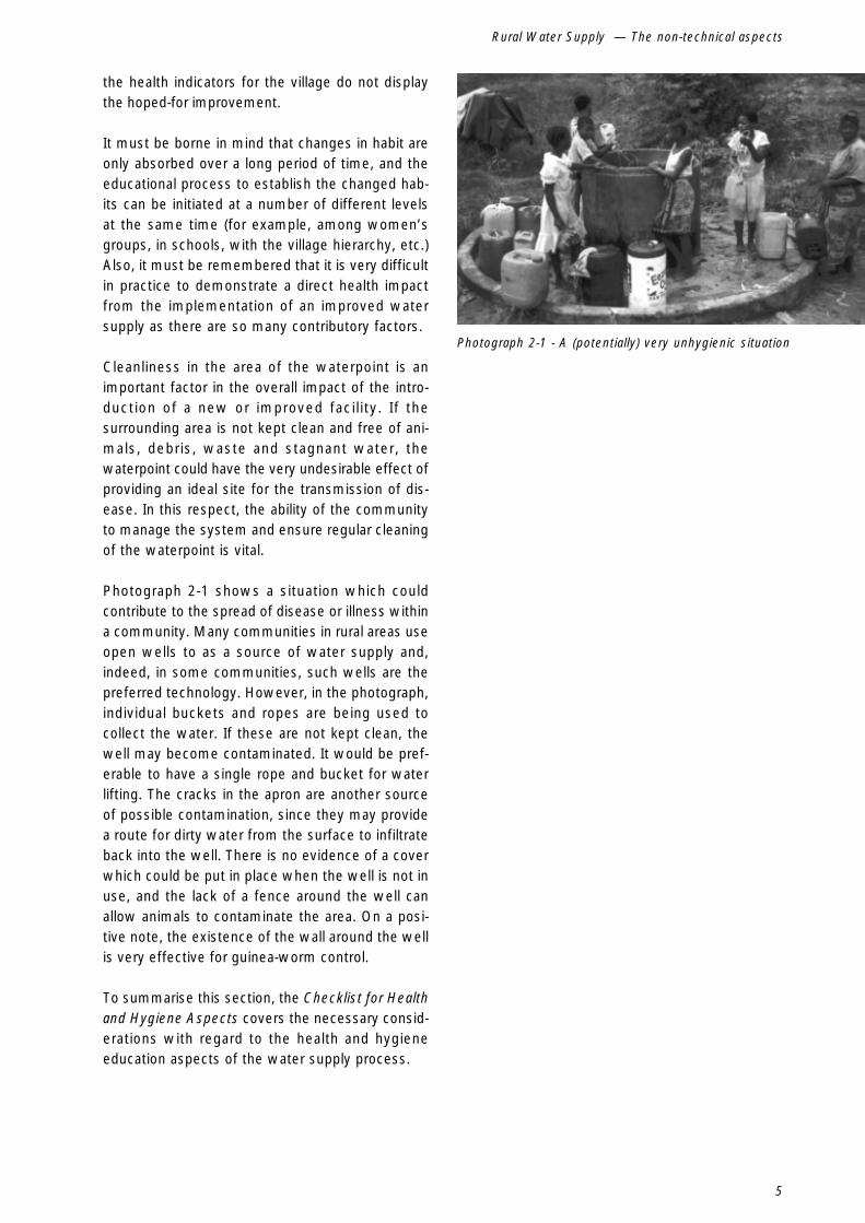
Cleanliness in the area of the waterpoint is animportant factor in the overall impact of the intro-duction of a new or improved facility. If thesurrounding area is not kept clean and free of ani-mals, debris, waste and stagnant water, thewaterpoint could have the very undesirable effect ofproviding an ideal site for the transmission of dis-ease. In this respect, the ability of the communityto manage the system and ensure regular cleaningof the waterpoint is vital.
Photograph 2-1 shows a situation which couldcontribute to the spread of disease or illness withina community. Many communities in rural areas useopen wells to as a source of water supply and,indeed, in some communities, such wells are thepreferred technology. However, in the photograph,individual buckets and ropes are being used tocollect the water. If these are not kept clean, thewell may become contaminated. It would be pref-erable to have a single rope and bucket for waterlifting. The cracks in the apron are another sourceof possible contamination, since they may providea route for dirty water from the surface to infiltrateback into the well. There is no evidence of a coverwhich could be put in place when the well is not inuse, and the lack of a fence around the well canallow animals to contaminate the area. On a posi-tive note, the existence of the wall around the wellis very effective for guinea-worm control.
To summarise this section, the Checklist for Healthand Hygiene Aspects covers the necessary consid-erations with regard to the health and hygieneeducation aspects of the water supply process.
Photograph 2-1 - A (potentially) very unhygienic situation

6
Hand-dug shallow wells
1 By the word institution we mean not only government institutions, NGOs, the private sector, etc., but also village level groupsand committees. In addition to describing an entity such as an agency, a department or a committee, the word is also takento mean an established habit or an accepted activity.
2.3 The management ofconstruction,operation andmaintenance
The idea that the activity of providing water suppliesneeds to be managed is so obvious that it may beoverlooked at the planning stage, and this oversighthas often led to problems, both during the execu-tion phase and during the operation and maintenancephase. In particular, the management of a systemafter its inauguration does not always receive dueattention, and it is in this area that the concept ofsustainability comes under the greatest pressure.Assumptions made and activities undertaken dur-ing the planning phase must be examined forlong-term implications, and measures must be takento ensure that the sustainability of the system is notcompromised.
The management of all phases depends critically onthe degree of community participation in each of therelevant activities. Community involvement andparticipation is a vital and indispensable element inthe long-term sustainability of water supplies, andthis concept must be reflected in the activities ofplanning, installing and managing the system. Thisinvolvement is of vital importance in the develop-ment of the critical sense of ownership which cancontribute to the long life and effective use of awater supply system. Such a sense of ownershipcannot be created instantly at the moment of inau-guration, but must be nurtured carefully from the verybeginning of the water supply process. To this end,for the overall success of a given system, strongand capable institutions must be in place before anywork is done1.
Checklist for Health and Hygiene Education Aspects
1. Is the link between water, sanitation and health understooda) in the providing institutionsb) among the village contact workersc) in the community in question?
2. If the above link is not understood, is a practice or capacity in place to bring the understanding to therelevant group, effectively and using appropriate methods?
3. Do the intended users of the new or improved system display an awareness of the need for hygienein water collection, storage and use?
4. If not, does an institution exist to work on developing such an awareness, and does it have the neces-sary capacity, particularly in relation to the use of participatory methods?
5. How much is currently known about the knowledge, attitudes and practices of the target group withregard to water use and health in general?
6. If little is known, does the capacity exist to conduct a detailed study of these aspects?
7. If there are already waterpoints in the community, are these well maintained?
8. Are there other activities, complementary to the provision of a water supply (e.g., latrine construction)taking place in the community already?
9. What is the degree of co-ordination, in the office and in the field, between the water, sanitation, healthand education sectors?

7
Rural Water Supply — The non-technical aspects
In relation to the installation of a water supplysystem, a given set of tasks must be executedand these must be undertaken by some person orentity capable of doing the job efficiently and effec-tively. Obviously, there must be sufficient resourceson hand to allow this to happen. The following pointsare relevant to the process:
The efficient performance of the above tasks isespecially important in relation to community par-ticipation, since the confidence of the users is anecessary element in the value which will be ulti-mately placed on the system and in developing theall-important sense of ownership which can contrib-ute to the long life of the installation. All theinstitutions involved in the process of planning, pro-viding and managing a water supply must be strongbefore the first activity gets under way, or at the veryleast be capable of developing at a pace with thenew installations and the consequent increase in thedemand for services from those institutions.
Representatives of the community (committees,action groups), of the government (both technical andadministrative, at each relevant level), of any in-volved NGO and of the private sector if such is thecase, must be able to absorb the workload intro-
duced by any new system. A good relationship be-tween institutions and users is also vital during theoperation, maintenance and management phasebecause it can ensure the collection of informationin the long term.
The concept of preventive maintenance is importantin the management of any water supply system.The long-term use of the installations can be assuredby regular replacement of wearing parts, annualmeasures against erosion, frequent cleaning of thewell and surrounding area and the development ofan awareness of the value of the waterpoint to thecommunity.
Closely related to the development and interactionof institutions, the importance of coherent policiescannot be over-emphasised. In addition to helpingdefine how the various institutions interrelate, poli-cies can facilitate the planning and implementationprocess through the establishment of procedures tobe followed in each phase of an activity. Policiescan contain guidelines for the provision of and pay-ment for services, in addition to technical parametersand standards. Establishment of clear procedures
� establishment of initial contact with the community;
� discussion with the community to ascertain priorities with regard to water supply in particular andthe overall development of the community in general;
� an explicit request, on the part of the community, for the provision of a new or improved water supplysystem;
� collection of information (demographic, social, economic, technical) about the project area;
� development or enhancement of a management capacity among the end users, which will ensurethat the community should be able to perform such tasks as preventive and corrective maintenance,financial management, erosion control, routine cleaning and resource management in times of scar-city;
� carrying out an accurate technical survey, to allow informed proposals to be made about technicaloptions;
� preparation of relevant technical documentation, to be presented and explained to the community,leading to the selection of one option by the community;
� execution of work in accordance with well-defined standards;
� supervision of work during construction;
� enabling and monitoring of the operation, maintenance and management of the completed system;
� inclusion of the community in a properly organised distribution network for spare parts, if possibleusing existing structures and institutions (such as the private commercial sector);
� depending on the installed technology, establishment of a qualified capacity to execute repair workbeyond the normal scope of the user community (e.g., a handpump mechanic)
� eventual replacement of broken, worn or obsolete parts (or entire systems)

8
Hand-dug shallow wells
with associated documentation can also help toensure that no steps in the process are omitted andthat each community is treated in a similar way.Procedures also make things easier for the imple-menting agency.
If clear and cohesive (but also flexible) policiesexist before any activity is undertaken in the field,there will be less confusion throughout the planning,construction and management phases, and no needto make one-off, ad hoc decisions which couldcreate conflict at a later time. Policies can definewho gets water, when, in what quantity, what tech-nologies can be offered, what is the degree offinancial contribution from the users of the system(for both construction and running costs), what arethe relative responsibilities of each of the actors inthe process, etc. It goes without saying that anypolicy should also be sufficiently flexible to allowregional, cultural, economic or technical variationsto be taken into account without having to redefinethe whole policy.
The issue of scale is also important. Projects involv-ing the construction of ten and one hundredwaterpoints will have different overall impacts butthe impact on the users of the new wells will besimilar in each case, and guidelines must be inplace to ensure the success of the process. Theneed for coherent policies is the same in any case,since a clear and flexible approach will be adapt-able to changing circumstances and will avoid theneed for frequent reversals or changes in the direc-tion of policy.
The following checklist summarises the points whichshould be considered in relation to the managementof the water supply process, from the planningstages to long-term operation and maintenance.
9
Rural Water Supply — The non-technical aspects
1 Throughout the Manual, we have used the hierarchy National–Regional–District–Village
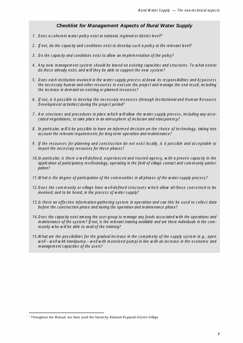
Checklist for Management Aspects of Rural Water Supply
1. Does a coherent water policy exist at national, regional or district level?1
2. If not, do the capacity and conditions exist to develop such a policy at the relevant level?
3. Do the capacity and conditions exist to allow an implementation of the policy?
4. Any new management system should be based on existing capacities and structures. To what extentdo these already exist, and will they be able to support the new system?
5. Does each institution involved in the water supply process a) know its responsibilities and b) possessthe necessary human and other resources to execute the project and manage the end result, includingthe increase in demand on existing or planned resources?
6. If not, is it possible to develop the necessary resources (through Institutional and Human ResourceDevelopment activities) during the project period?
7. Are structures and procedures in place which will allow the water supply process, including any asso-ciated negotiations, to take place in an atmosphere of inclusion and transparency?
8. In particular, will it be possible to have an informed decision on the choice of technology, taking intoaccount the relevant requirements for long-term operation and maintenance?
9. If the resources for planning and construction do not exist locally, is it possible and acceptable toimport the necessary resources for these phases?
10.In particular, is there a well-defined, experienced and trusted agency, with a proven capacity in theapplication of participatory methodology, operating in the field of village contact and community partici-pation?
11.What is the degree of participation of the communities in all phases of the water supply process?
12.Does the community or village have well-defined structures which allow all those concerned to beinvolved, and to be heard, in the process of water supply?
13.Is there an effective information-gathering system in operation and can this be used to collect databefore the construction phase and during the operation and maintenance phase?
14.Does the capacity exist among the user group to manage any funds associated with the operations andmaintenance of the system? If not, is the relevant training available and are there individuals in the com-munity who will be able to avail of the training?
15.What are the possibilities for the gradual increase in the complexity of the supply system (e.g., openwell – well with handpump – well with motorised pump) in line with an increase in the economic andmanagement capacities of the users?

10
Hand-dug shallow wells
2.4 Economicimplications andimpact
The construction, operation and maintenance ofwater supply systems is never free, whether thepayment is made by the government, by a donor,by a private individual or by the community itself.In most cases funding comes from a mixture ofthese sources. The construction of a rural watersupply introduces a new element into the economy,either local, regional or national, and the impact ofthis must be catered for. Even the most basic eco-nomic unit, the family or individual producer, will beaffected in some way, since a certain amount ofhousehold income will be absorbed by the new sys-tem.
Depending on the technology applied costs will vary,both for the capital investor (government, donor,community, NGO, private sector company or a com-bination of these) and for the long-term operators andusers. If a choice is allowed by the ground condi-tions, the range of possible technologies which canbe applied must be drawn up. If it is envisaged thatthe local and national economy will grow, the wa-ter supply system may be installed in a step-wiseprocess, allowing expansion in size and/or increasein technology and running costs as (and if) thelocal economy develops the necessary financial (andmanagement) capacity. If the economic capacity of
the end users is unable to meet the demands ofoperating a certain technology, then unless there isa viable and sustainable alternative for meetingoperation and maintenance costs, the proposedtechnology must be reviewed and a more viableoption chosen. If the proposed technology is the onlytechnically viable solution, and if other factorsdemand that a service be provided, a clear policymust be formulated which takes account of the situ-ation but which serves to introduce the highestpossible degree of sustainability into the installedsystem. In the ideal situation, the future users ofa system should be presented with the range ofviable options and the associated capital and run-ning costs, and should decide which option theywant to adopt.
The state of activity of local economies is animportant factor in a number of other aspects. Ifthere is a vibrant local economy, there may be pri-vate traders who would be willing to carry a stockof spare parts, thus avoiding the need to set up aseparate distribution system and allowing the re-sponsibility for routine repairs to pass solely to theusers or managers. In such a situation also, it willbe easier to set up water vending or maintenancecost recovery schemes. Of course, the success ofsuch schemes depends to a great extent on the levelof priority afforded to their water supply by the com-munity in question, and this relates back to theconcepts of community participation and education.
Checklist for Economic Implications and Impact
1. Who, or which institution, is expected to provide the necessary finance for each of the planning,construction and management phases?
2. Is there any objective evaluation of the willingness and ability of the community to pay for water?
3. What is the present economic capacity of each of the actors in the water supply process, including theend users?
4. Is this economic capacity sufficient to meet the planned contribution to each of the phases mentionedabove?
5. If not, what policies are to be applied?
6. Will the new system be managed by a private operator? If so, does this private operator have the eco-nomic capacity to ensure a proper operation of the system?
7. Will the community be expected to pay for water? For spare parts? For repairs?
8. Is there a clear policy and legal basis for these payments?

11
Rural Water Supply — The non-technical aspects
Photograph 2-2 - Women congregating at a waterpoint.The daily collection of water is very muchasocial activity.
Two critical aspects in ensuring long-term viabilityof water supply systems are ability and willingnessto pay, on the part of the users, for the serviceprovided. An ability to pay may be reflected ina buoyant local economy, but, without a corres-ponding willingness, the future operation andmaintenance of the system cannot be assured. Thevarious aspects of payment for water supplied torural communities are the subject of a large bodyof specialised literature, and are beyond the scopeof this manual. The interested reader is referred tothe relevant titles indicated in Appendix 1.
2.5 Social, culturaland environmentalaspects
Among other aspects which must be considered arethe impact of the proposed system on the localenvironment. For example, the operation of the sys-tem may involve the emission of waste gases orliquids, or the catchment and consumption ofwater may deny a supply to other human users,wildlife or plant life. Again, the construction of a sys-tem might create problems with erosion in the areaof the installation. The possibility of increased usewith increased availability, and the possibility ofincreased consumption with an increase in popula-tion must be taken into account at the planningstage.
In many societies the collection of water has adefinite place in the social fabric of a community,and the roles of various groups in relation to watercollection and use are well-defined. For manywomen, the collection of water provides an oppor-tunity for social interaction and is an important partof the day. Whether or not the collection of wateris a burden on a particular group within a commu-nity cannot be judged accurately from outside,without understanding the place of the activity in thewhole social fabric of the community. The introduc-tion of a new system, perhaps in a different locationor using a different technology, can have socialrepercussions and can lead to some intangible prob-lems in the operation and maintenance phase. Inthis respect, the full participation of all members ofa community throughout the whole process of con-structing a new or improved water supply is of theutmost importance.
Of particular importance in this respect is the gen-der division of labour with regard to water collection,storage and use. The daily collection of water is atask performed by women and children throughoutthe world, and it is a task which has developed adefinite niche in the social fabric of community life.A new or improved water supply system will havean effect on the equilibrium of this activity as it re-lates to other tasks which are the responsibility ofwomen. The establishment of a waterpoint closerto the village may mean than time formerly spenttravelling to collect water becomes available forother tasks. Again, the shorter time spent collect-ing water may yield less opportunity for socialintercourse among the women of a village. Wherewater is subject to charges, for consumption and/or for maintenance, this will also have an effect onthe household economy and on the family memberresponsible for the budget. Hence, the introductionof a water supply system may disturb the genderbalance in a society, or within the family unit. Thismay become clear already at the planning stage,when it should become clear which group makesthe decisions for a village. In many cases, this groupmay not adequately represent those to be especiallyaffected by the proposed changes. For this reason,it is important that a balance be struck as early aspossible in the planning process between all inter-est groups, including those formed on the basis ofgender roles.

12
Hand-dug shallow wells
Checklist for Environmental, Social and Cultural Aspects
1. Does the environment in the target area merit special attention (for example, due to wildlife, plant life,susceptibility to erosion) above the normal considerations?
2. Will the construction or operation of the proposed system introduce practices which could be harmfulto the local environment in the short or long term?
3. Will the operation of the system cause an appreciable drop in the local water table and will this affectthe environment adversely?
4. Is the proposed technology compatible with the local environment?
5. Do current practices in the target area, in relation to water collection, mean that certain technologiescannot be considered?
6. Within the target community, do the traditions of decision-making allow for the voices of all groups tobe heard and considered?
7. In particular, are women included fairly in decision-making processes?
8. Are all the relevant cultural aspects of water collection and use understood?
9. In particular, what is the role of women with regard to water collection, storage and use?
10.What is the tradition regarding the intra-household distribution of resources?

13
Rural Water Supply — The non-technical aspects
2.6 Preconditions forsuccessful watersupply activities
The foregoing has shown that the introduction of anew or improved water supply system into a com-munity is much more than a straightforwardtechnical activity. Similarly, the decision to constructa hand-dug well cannot be made only by followinga set of technical criteria. The criteria listed belowmust be satisfied if a water supply process is tobe assured of any degree of success.
� A cohesive and comprehensive water policy is in place.
� The institutional set-up in the Water Sector is such that the construction activities, and the subse-quent operation, maintenance and monitoring of the systems (including the distribution of spare parts),will not overload the Sector or any of its components.
� Community participation is assured.
� Future management of the system is assured through the existence of the necessary institutions.
� There is a clear policy on the financing of construction, operation and maintenance costs, whetherthis involves direct payment by the users, government subsidies, contracting of private individualson a commercial basis etc. All those involved understand their roles and responsibilities and are ina position to fulfil them.
� Links are established with the relevant institutions in the areas of health, education and agriculture.
� There is adequate information available about the knowledge, attitudes and practices in the commu-nity with regard to health, hygiene and water collection, storage and use. In addition, there is acapacity to follow-up on this information and to put in place a process of continued training/educa-tion and enforcement.
� There is sufficient technical information about the groundwater regime in the proposed location, ora capacity exists to do a survey or contract the necessary expertise to do it.
� Technical expertise, and the necessary resources, exist at the appropriate institutional levels, andare available to construct, supervise and maintain the system.
� Requirements for the location of the proposed sites, as detailed in Section 6.3 are satisfied.
� The proposed sites are accessible to the various types of transport which will be necessary duringthe planning, construction and maintenance phases, or such access can be guaranteed by the re-quired date.
14
Hand-dug shallow wells
2.7 Conclusions
There may be other points to consider in a particu-lar case, such as the logistics of bringing heavyequipment over long distances or the availability ofsuitably-qualified staff at the planned location. In anycase, it will be clear that there are complex inter-relationships between the various non-technicalaspects of the water supply process. No single as-pect can be considered in isolation, since this wouldinvolve making limiting assumptions about the in-fluence of the other parameters. In the end, adecision must be made on the relative priorities ofeach aspect, considered against a community’sneed for a supply of drinking water. In this respect,a set of basic principles as defined in a good waterpolicy is of particular importance.
This chapter has attempted to give a brief overviewof the important non-technical considerations in re-lation to rural water supply projects and systems.For a more comprehensive treatment of the subject,the reader is referred to Volume 1 in this series ofManuals.

15
Technical aspects of rural water supply
3.Technical aspects of rural water supply
3.1 Introduction
The previous section considered the non-technicalaspects of the introduction and management of awater supply system. This section will focus on thetechnical side, and will emphasise the technicalconsiderations related to the construction of hand-dug wells. At the outset, it is important once moreto put the technical aspect of water supply in con-text. For any given situation, there will be a rangeof technically feasible solutions. However, even themost appropriate technical solution will not prove
sustainable if due consideration is not given to non-technical aspects, as treated in Chapter 2. Similarly,an inappropriate technical solution will make a sys-tem unmanageable and unsustainable even whenall other non-technical factors are considered andresolved in the most sustainable manner possible.
3.2 The occurrence ofgroundwater
3.2.1 The Hydrological Cycle
Figure 3-1 - The Hydrological Cycle

16
Hand-dug shallow wells
The hydrological cycle, also known as the watercycle, is the constantly-occurring process whereby,in simplified terms, water falls to the ground as rain,or other precipitation, runs along the ground underthe force of gravity or percolates down to an imper-meable layer of soil or rock, appears again at thesurface, eventually reaches the sea or a lake andevaporates to form clouds which produce rain. Thisprocess is represented graphically in Figure 3.1. Inits use of water for various activities, the world’spopulation intervenes in this cycle at a number ofpoints. For the purpose of this manual, we are in-terested only in the exploitation of water as it passesthrough shallow aquifers, when it is referred to asgroundwater.
3.2.2 Types of aquifer
Figure 3.2 illustrates the various types of aquifer
which can occur. Aquifers may be classified broadlyin three categories, namely,
� confined aquifers are water-bearing stratawhich lie between two impermeable layers.Water in these aquifers is often under pressureand, if the upper impermeable layer is breachedby a borehole, the water from the aquifer will riseto its piezometric level. Where this piezometriclevel is above ground level, water will emergefrom the borehole under pressure and will gushup into the air. This is referred to as an artesianwell. In a case where the piezometric levelis below ground level, but above the level of thetop of the confined aquifer, this is known as asub-artesian well. Note that the piezometric pres-sure line refers only to the water in the confinedaquifer.
Figure 3-2 - Types of Aquifer

17
Technical aspects of rural water supply
� unconfined aquifers occur when the water-bearing stratum is not covered by an im-permeable layer. In this situation, the water inthe aquifer is not under pressure, and will not risein a borehole or well which reaches the level ofthe aquifer. The level of water in this aquifer willfluctuate with the seasons, and care must betaken when exploiting such an aquifer for watersupply purposes.
� perched aquifers are a special case of un-confined aquifers. These occur where water, asit percolates down from the surface, is trappedby an isolated impermeable layer, of limitedextent, within otherwise permeable strata.Unless the impermeable stratum is very exten-sive, a perched aquifer is recharged only bylocally-occurring rainfall and will provide at besta seasonal supply of water.
3.3 Water quantity
3.3.1 Supply and demand
The consumption of water is a question of supplyand demand, and increased availability and acces-sibility usually lead to increased consumption, atleast up to a certain point. It is difficult for plannersto predict the future rates of consumption in orderto have some guidelines for dimensioning a planned
system. Many agencies do not have the resourcesto conduct detailed surveys in each location duringthe planning stage. In any case, the introduction ofa survey into a particular community might evenhave the effect of temporarily altering consumptionpatterns and thus yielding a false basis for planning.In most cases, planners depend on broad estimatesand, taking physical and financial limitations intoaccount, try to allow generously for increased con-sumption and population growth in the future. Itis essential that relevant guidelines exist, so that adegree of cohesion and equality can be ensured ina country’s water supply programme. Estimates forthe consumption of water in rural communities varyfrom country to country, but the table below isindicative of the normal ranges applied.
Countries will adopt their own coverage criteriain accordance with the general policy for watersupply, taking into account demographic, physical,financial, economic, technical and other considera-tions. In some countries the target level of coveragemay be expressed in a given quantity of water perperson per day. In others, it may be given as theprovision of a waterpoint within a certain maximumwalking distance from a given number of users.Whatever the situation, the providing agency mustdefine its objectives in terms of the levelof service to be provided to the rural communitiesand pursue programmes and technologies whichguarantee this level.
Table 3-1 - Ranges of Water Consumption
Type of Supply/User Typical Daily Consumption(litres per person per day)
Communal well with handpump at: 1km distance 5-10500m 10-15250m 15-25
Neighbourhood well/standpipe 20-15Standpipe in yard (exclusive to household) 20-80Water piped into house (single tap) 30-60Water piped into house (multiple taps) 70-200School - day students, per student 6-15
- boarding students, per student 40-80Hospital, per bed 200-500

18
Hand-dug shallow wells
During the planning process, it must be borne inmind that the concept of an acceptable or appropri-ate level of service may be interpreted differentlyby the different participants in the water supplyprocess. It is important that all possibilities and per-ceptions be thoroughly debated, explained andnegotiated to an acceptable compromise at the plan-ning stage, to avoid confusion, misunderstanding ordisappointment later. It is vital that a new orimproved water system satisfy the users in termsof their general expectations, (for example, in theincreased convenience brought by the system or thevolume of water which will be available), and thatthe limitations of any technical solution are explainedclearly. If this is not done, and if there is not suffi-cient education about proper practices in relation towater collection and use, the community may wellignore the maintenance of the new system and optto use less hygienic sources. If the community’sexpectations are unrealistic (in terms of the sophis-tication of the new system, the real capacity of theaquifer to be exploited, the probable costs of opera-tion and maintenance, the price to be paid by theconsumers, the input expected from the communityin terms of management of the system etc.),representatives of the service providers must ensurethat people are informed of what is actually possi-ble in a given situation.
The level of use of a system must be taken intoaccount in the planning stage. If, for example, a ratioof 1 waterpoint to 500 people is applied, the instal-lations will receive twice as much wear as if aratio of 1 to 250 were applied. Obviously, the invest-ment costs in the latter case will be greaterthan those in the former but, in the long term,considerations of use, wear and tear and routinemaintenance must be taken into account in relationto considerations of initial capital investment. More-over, a higher level of service will normally resultin an increased willingness to maintain and pay fora system.
3.3.2 Exploiting and managingthe water resource
To ensure the long-term sustainability of a resource,its consumption must be balanced with the capac-ity for renewal and the needs of the users of theresource. The amount of water made available andcollected on a given day will depend on the yield ofthe source, the time of year and the capacity of the
applied technology to carry the water to its point ofuse. In many cases, since the amount of wateravailable will vary with the time of year, or from yearto year, it will be necessary for the users to man-age the water provided, particularly (but not only) attimes of scarcity.
While it may be obvious that the basic goal is foreveryone to have access to water in whatevermonth of the year, at whatever time of the day, thisassumption may be limited by the physical condi-tions at a given location. Planners must take intoaccount these factors, and propose a technicalsolution which assures the highest possible degreeof service at all times of the year. Drilling a boreholeinto an aquifer that does not recharge at a reason-able rate, and installing a handpump, will lead todamaged equipment and frustrated users. Excavat-ing a hand-dug well in an area where the water tableis known to be unreliable and subject to a highdegree of fluctuation will have the same effect.
While the focus of the present Manual is primarilyon the supply of water for domestic consumption,it may happen that not all the users of a well willdraw water for this purpose. Also, within a smallarea, the same aquifer may be exploited for anumber of different purposes and at a number of dif-ferent locations, both private and public. Activitiessuch as irrigation or a commercial activity such asa laundry service can consume a high volume ofwater on a daily basis. In such a situation, priori-ties must be defined and the exploitation of the waterresource regulated so that essential needs are sat-isfied before the water is used for non-domesticpurposes. For example, the use of water for large-scale irrigation must not be allowed to depress thewater table to an extent which would deny asupply to domestic users. Another important con-sideration is the recharge of the aquifer, and theprotection of the recharge area against contamina-tion. Since the location in which recharge takesplace is not always near the point of use of thewater, the existence of a comprehensive waterpolicy is very useful in such cases.

19
Technical aspects of rural water supply
3.4 Water quality
3.4.1 Drinking water qualityand monitoring
The provision of water in plentiful quantities is asignificant factor in the improvement of the healthstatus of a community, particularly in relation to thewater-washed diseases mentioned in Section 2.2.1.However, contact with contaminated water duringwashing can result in infection with other diseasessuch as those classified as water-borne or water-based. In addition, if the water is to be used for foodpreparation and drinking, it must be borne in mindthat infectious diseases caused by pathogenicmicro-organisms or by parasites constitute themost common health risk related to drinking water.Taking this into account, the final decision on theconstruction or improvement of a waterpoint can-not be made unless there is evidence that, as wellas providing water in sufficient quantities, the result-ing waterpoint will constitute a real improvement inthe quality of water available to the community.
Whether or not water is provided treated or untreatedat the point of collection will depend on the degreeof purity of the raw supply, the mechanisms andresources in place for monitoring and treatment andthe accepted practices in the community withregard to the collection, storage and use of water.It must be stressed that the provision of clean waterat the point of collection does not guarantee theavailability of clean water at the point of use.
The World Health Organisation has produced aseries of guidelines for drinking water quality.1 Thepoint is made that the values given, for variousmicrobiological, chemical and other indicators, servemerely as guidelines, and each national waterauthority will develop standards based on the localsituation. The guidelines cannot be viewed in isola-tion from environmental, social, economic andcultural factors, and any national standards, whetheror not they are based on the guidelines, should takeall these factors into account. Also, it should beborne in mind that an intervention in a particularwater supply situation may not result in a supply ofwater which satisfies national guidelines, but doesresult in a considerable improvement over the
initial situation. One possible example could be theprovision of rainwater catchments in an area wherethe groundwater conductivity is above nationally-accepted guidelines. At least during the rainy season,the users would have an alternative supply of drink-ing water. The need for improved water suppliesexists even in areas where national standards can-not easily be met.
One of the most common indicators used for drink-ing water quality is the presence of coliform bacteria.Testing may be done for faecal coliforms or for alltypes of coliform. An indication of the presence offaecal coliforms in a water sample shows that therehas been contamination by humans or other warm-blooded animals, which in turn indicates the dangerof infection by other pathogens. Testing for totalcoliforms is less useful, since other coliform bacte-ria are quite common in the environment, and theirpresence in a water sample does not necessarilyindicate faecal contamination. The WHO guidelinessuggest that no coliform (E. coli, thermotolerant orother coliform) bacteria should be present in any100ml sample of water.
However, it is frequently not possible, for financial,logistical or personnel reasons, to be able to con-duct regular and frequent monitoring of water quality,especially at a local level. In any case, measuringwater quality at the point of collection does not takeaccount of transport and storage practices. Anotherproblem with water quality monitoring is that theresults of a test, however careful and accurate, in-dicate the situation at one point in time, making noallowance for the possibility that the situation coulddeteriorate soon after the extraction of the sample.
The best option in such cases is to adopt a regimeof risk assessment and risk minimisation called asanitary survey. This is a very valuable technique,requiring very little investment or training for fieldapplication, and is of particular value for hand-dugwells. The quality of water at the point of collectioncan only be assured by introducing measures forpollution control at the well itself. These can includelining the well, observing the guidelines for thepositioning of the waterpoint (see Section 6.3),covering the well, fitting a self-priming handpump,constructing an apron at the well-head and
1 WHO, Guidelines for drinking-water quality, 2nd ed., Vols. 1-3, Geneva, 1993
20
Hand-dug shallow wells
ensuring that the area around the well is kept cleanand free of stagnant water and animals. Thesemeasures should ideally be implemented in tandemwith a programme of education on hygiene andhealth in relation to water use. If the sanitary sur-vey is repeated at regular intervals (for example,once a year), an increase in the assessed risk willindicate the need for corrective measures.
During the initial visit to a proposed waterpoint site,the technical team may not be in a position to doan in-depth water quality analysis. An extensiverange of indicators cannot be measured in field tests,and will also be outside the scope of many labora-tories in countries of the South. A number of criteria,mainly empirical, may be applied in the field whichwill indicate whether or not it is advisable to con-tinue with the installation of a waterpoint. Watershould be tasteless, odourless and, after settling ina container, clear and colourless. It should not con-tain any visible living organisms such as worms,nor any waste, oil or plant matter. For quick fieldmeasurement of the concentration of certain chemi-cals, specific indicator strips are available, andlitmus paper can be used to check the pH.
A word of caution is necessary here. While it is notat all intended to discourage the establishment ofsystems for the continuous surveillance of drinkingwater quality, anyone considering the setting-up ofsuch systems must take into account all the asso-ciated implications. Surveillance is a necessary partof the operation and maintenance phase of anywater supply system2, but the type of surveillanceregime adopted must be compatible with the givensituation, and must produce reliable, useful results.At first glance, the surveillance of drinking waterquality may seem like a straightforward technicalactivity, but it must be borne in mind that this ac-tivity takes place within the complex situation ofwater supply systems, often in areas which arebadly served by infrastructure, communications andresources (both human and material). While field kitsare available to check for the presence of specificcontaminants, no testing regime should be initiatedunless there are concrete guarantees that the nec-essary resources are available to ensure long-term,frequent and regular testing. Data from isolated testscan only give a distorted view of an already-
complex situation. For these reasons, it is advisablethat any surveillance regime take full account ofexisting and future resources.
Again, quite apart from the technical considerations,mechanisms must be in place (and adequatelyresourced) to allow for a rapid response to theresults of quality testing. If, for example, a well isshown to be contaminated, a procedure must bedefined (and accepted beforehand by all actors) forclosure of the well, repetition of the test, treatment,further testing and eventual reopening. It is not suf-ficient merely to ascertain that a source is polluted.In this regard, the strength of the operation andmaintenance regime, and of the institutions involvedin it, are critical.
In conclusion, it can be said that a good and effec-tive water quality surveillance regime need notnecessarily include frequent chemical testing, eitherin the field or in a laboratory. An appropriate schemewill include proper siting of the waterpoint and theregular assessment and minimisation of the risk ofcontamination, in association with a comprehensiveregime of sanitary management.
A more in-depth discussion of water quality analy-sis is outside the scope of this manual and theinterested reader is referred to the specialised textsmentioned in Appendix 1. For a more comprehen-sive introduction to the subject, the reader canconsult the relevant chapter in Volume 2 of thisseries.
3.4.2 Disinfection
During the construction phase the water in the wellwill become contaminated due to labourers stand-ing in it, debris falling in etc. Upon completion of thewell, but before any water is collected and used, adisinfection of the well must be carried out using,usually, chlorine. The subject of disinfection ofa completed well is treated in more detail inSection 10.2.
During the normal operation phase of a waterpoint,the decision about a disinfection regime should fol-low the considerations outlined above for thesurveillance of water quality. Essentially, any such
2 The subject is treated at some length in volume 3 of the aforementioned WHO Guidelines for Drinking Water Quality

21
Technical aspects of rural water supply
procedures must take account of local capacitiesand practices. While disinfection at regular intervalswould be generally desirable, local conditions (insti-tutions, resources and level of supply) must allowfor the closure of the well, testing of the well aftertreatment and the capacity to declare the water safefor human consumption once more (free fromresidual traces of the disinfecting agent). The hap-hazard, ineffective and unregulated treatment ofwaterpoints could have a detrimental effect on thehealth of the users, to say nothing about the nega-tive effect on the sense of ownership of orresponsibility for the system.
In cases where there is an outbreak of a water-related disease, such as cholera, suspect water-points must be closed and disinfected in accordancewith strict guidelines, normally overseen by thehealth sector.
3.5 Technicalrequirementsfor construction,operation andmaintenance
It is stating the obvious to say that, in order toconstruct a water supply system, the capacity todo so must already exist. Leaving aside for themoment the important non-technical aspects ofcommunity contact and capital funding, the ultimateprovider of the water system must have a varietyof technical, human and other resources available.The following checklist gives an indication of theseresources.
Checklist for Resources Necessary for Water SupplyConstruction and Maintenance
1. Resources for the carrying out of detailed surveys of the water resources in a given area, including:a) Information on the geology of the proposed location from maps, a relevant data base or other
reports;b) Information on the groundwater resources in the area from previous installations, reports, borehole
logs, etc.;c) Information on the rainfall patterns in the area;d) Information on activities (agricultural, mining, industrial, etc.) in the area of recharge of the aquifer
to be exploited;e) Equipment to perform the necessary survey, whether geophysical soundings, a manual test
borehole, spring measurement etc.;f) Personnel to perform the survey and interpret the results. In the case of geophysical surveys, a
qualified hydrogeologist will be needed;g) Personnel to receive and check the report on the survey.
2. Resources to design the proposed system, including the production of relevant drawings, technicalstandards and contract documents.
3. Personnel capable of doing the physical work in accordance with the prepared instructions.
4. Personnel capable of conducting the necessary supervision of the construction work to ensurecompliance with standards and efficient execution of work.
5. Personnel to work in the area of capacity-building (teaching the users to manage and use the system),using effective and appropriate participatory training methods.
6. Transport for survey, construction (personnel and materials) and supervision.
7. Resources to guarantee the smooth introduction and management of the Operation and Maintenancephase.

22
Hand-dug shallow wells
In the early stages of a project, all the above-listed resources may not be available, and initialworks may be used as part of a staff training plan.The construction of water supplies may wellgo ahead without some of the resources, but theproject will eventually run into difficulty at somestage. Once again, the scale of the undertaking isimportant. Large-scale projects covering a consid-erable area or population will require much moreresources than smaller works. What is critical isthat procedures are in place which can be adaptedto the size of any undertaking. It is not necessarythat all the above listed resources be located inone organisation or agency, but the resources mustbe available to the project, either directly from theagency implementing the process, or throughcontracts awarded by that agency.

23
Options for water supply technologies
4.Options for water supply technologies
4.1 Introduction
Hand-dug wells do not provide the only option forthe exploitation of groundwater, and there are manycases in which the application of the technologywould be quite inappropriate. While the range oftechnologies for well construction and for water lift-ing is quite broad, there are basically three methodsfor gaining access to groundwater for collectionpurposes. Apart from these three basic options,water may be taken directly from a river or lake, orcaptured when it falls as rain. The options are sum-marised in the following list:
� Rainwater catchment
� Surface water intake– River– Lake– Artificial dam
� Groundwater exploitation– Spring catchment– Bored well– Hand-dug well
There are other specialised technologies such as,for example, cloud harvesting and the use of reverseosmosis to convert sea-water to potable water, butthese are of limited application in rural communities.It is outside the scope of this Manual to give anin-depth treatment to all the possible technicaloptions for water supply systems. However, thischapter will give a brief overview of the availabletechnologies for groundwater exploitation, with theintention of showing the option for hand-dug wellswithin the overall context of rural water supplies. Formore detailed information regarding the range ofoptions available, the reader is referred to the pub-lications mentioned in Appendix 1.
4.2 Spring catchments
Strictly speaking, we are not dealing with ground-water in this case. As shown in Figure 3.2, springsoccur where water which has been flowing alongthrough an aquifer appears at ground level. Rainwaterinfiltrates into the soil and passes through a perme-able stratum. The water continues to seepdownwards until it reaches an impermeable layer,flowing along the top of this layer until it reachesthe surface. This is known as a gravity contactspring. There are other types of spring also (fractureand tubular, back-stowing, mountain slide and arte-sian) and the reader is referred to the morecomprehensive treatment in the Manual on SpringCatchment 1. The essential nature of a spring is thatwater appears flowing freely at ground level and hasto be “captured” in order to be stored and used. Thiscatchment involves a structure to direct the waterfrom the spring to a storage chamber, from wherethe water can either be collected directly by the usersor piped (normally under gravity) to a distributionsystem.
The main advantages of a spring catchment arethat it can provide a plentiful supply of clean waterand, with a distribution system, can bring waterdirectly into a village using a system requiring littlemaintenance, the costs of which are comparativelylow. The disadvantages are that a system is noteasily extended to cater for increased use, as thiscould involve the capture of a new spring, essen-tially a whole new construction project, and theflow in the spring can be influenced greatly by rain-fall levels.
1 Volume 4 in this series
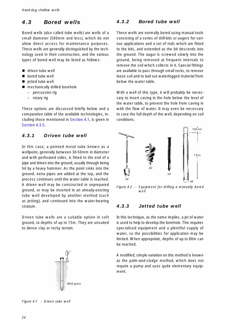
24
Hand-dug shallow wells
4.3 Bored wells
Bored wells (also called tube wells) are wells of asmall diameter (500mm and less), which do notallow direct access for maintenance purposes.These wells are generally distinguished by the tech-nology used in their construction, and the varioustypes of bored well may be listed as follows:
� driven tube well� bored tube well� jetted tube well� mechanically drilled borehole
– percussion rig– rotary rig
These options are discussed briefly below and acomparative table of the available technologies, in-cluding those mentioned in Section 4.1, is given inSection 4.3.5.
4.3.1 Driven tube well
In this case, a pointed metal tube known as awellpoint, generally between 30-50mm in diameterand with perforated sides, is fitted to the end of apipe and driven into the ground, usually through beinghit by a heavy hammer. As the point sinks into theground, extra pipes are added at the top, and theprocess continues until the water table is reached.A driven well may be constructed in unpreparedground, or may be inserted in an already-existingtube well developed by another method (suchas jetting), and continued into the water-bearingstratum.
Driven tube wells are a suitable option in softground, to depths of up to 15m. They are unsuitedto dense clay or rocky terrain.
4.3.2 Bored tube well
These wells are normally bored using manual toolsconsisting of a series of drill-bits or augers for vari-ous applications and a set of rods which are fittedto the bits, and extended as the bit descends intothe ground. The augur is screwed slowly into theground, being removed at frequent intervals toremove the soil which collects in it. Special fittingsare available to pass through small rocks, to removeloose soil and to bail out waterlogged material frombelow the water table.
With a well of this type, it will probably be neces-sary to insert casing in the hole below the level ofthe water table, to prevent the hole from caving inwith the flow of water. It may even be necessaryto case the full depth of the well, depending on soilconditions.
4.3.3 Jetted tube well
In this technique, as the name implies, a jet of wateris used to help to develop the borehole. This requiresspecialised equipment and a plentiful supply ofwater, so the possibilities for application may belimited. When appropriate, depths of up to 80m canbe reached.
A modified, simple variation on this method is knownas the palm-and-sludge method, which does notrequire a pump and uses quite elementary equip-ment.
Figure 4-1 - Driven tube well
Figure 4-2 - Equipment for drilling a manually boredwell
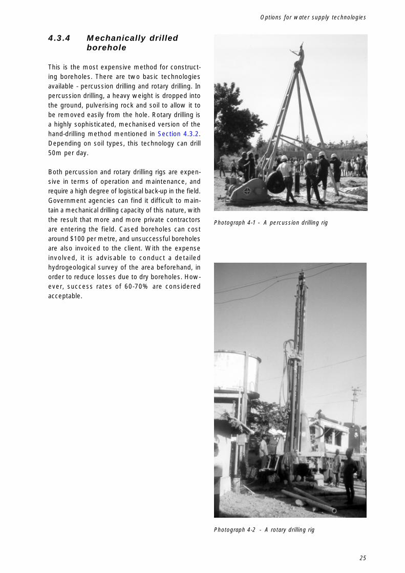
25
Options for water supply technologies
4.3.4 Mechanically drilledborehole
This is the most expensive method for construct-ing boreholes. There are two basic technologiesavailable - percussion drilling and rotary drilling. Inpercussion drilling, a heavy weight is dropped intothe ground, pulverising rock and soil to allow it tobe removed easily from the hole. Rotary drilling isa highly sophisticated, mechanised version of thehand-drilling method mentioned in Section 4.3.2.Depending on soil types, this technology can drill50m per day.
Both percussion and rotary drilling rigs are expen-sive in terms of operation and maintenance, andrequire a high degree of logistical back-up in the field.Government agencies can find it difficult to main-tain a mechanical drilling capacity of this nature, withthe result that more and more private contractorsare entering the field. Cased boreholes can costaround $100 per metre, and unsuccessful boreholesare also invoiced to the client. With the expenseinvolved, it is advisable to conduct a detailedhydrogeological survey of the area beforehand, inorder to reduce losses due to dry boreholes. How-ever, success rates of 60-70% are consideredacceptable.
Photograph 4-1 - A percussion drilling rig
Photograph 4-2 - A rotary drilling rig
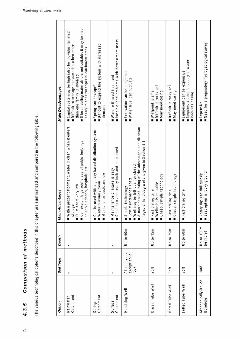
26
Hand-dug shallow wells
4.3
.5C
om
pari
son
of
meth
od
s
The
vario
us t
echn
olog
ical
opt
ions
des
crib
ed in
thi
s ch
apte
r ar
e su
mm
aris
ed a
nd c
ompa
red
in t
he f
ollo
win
g ta
ble.
Opt
ion
Rai
nwat
erC
atch
men
t
Spr
ing
Cat
chm
ent
Sur
face
Cat
chm
ent
Han
d-du
g W
ell
Driv
en T
ube
Wel
l
Bor
ed T
ube
Wel
l
Jett
ed T
ube
Wel
l
Mec
hani
cally
-Dril
led
Bor
ehol
e
So
il T
ype
- - - All
soil
type
sex
cept
sol
idro
ck
Sof
t
Sof
t
Sof
t
Har
d
Dep
th
- - - Up
to 6
0m
Up
to 1
5m
Up
to 2
5m
Up
to 6
0m
Up
to 1
00m
(or
mor
e)
Mai
n A
dva
nta
ges
�W
ith a
pro
per
catc
hmen
t, w
ater
is c
lean
whe
n it
ente
rsst
orag
e�
O+
M c
osts
ver
y lo
w�
Can
exp
loit
larg
e ro
of a
reas
of
publ
ic b
uild
ings
to s
erve
sch
ools
, hos
pita
ls, e
tc.
�C
an b
e us
ed w
ith a
gra
vity
-bas
ed d
istr
ibut
ion
syst
em�
Wat
er is
usu
ally
cle
an�
Mai
nten
ance
cos
ts a
re lo
w
�M
aint
enan
ce o
f in
take
is e
asy
�S
mal
l dam
s ar
e ea
sily
bui
lt an
d m
aint
aine
d
�S
impl
e te
chno
logy
�Lo
w m
aint
enan
ce c
osts
�W
ell m
ay b
e le
ft o
pen
or c
lose
d�
A m
ore
deta
iled
listin
g of
the
adv
anta
ges
and
disa
dvan
-ta
ges
of h
and-
dug
wel
ls is
giv
en in
Sec
tion
5.3
�Fa
st d
rillin
g tim
e�
Wel
lpoi
nt i
s re
usab
le�
Che
ap,
sim
ple
tech
nolo
gy
�Fa
st d
rillin
g tim
e�
Che
ap,
sim
ple
tech
nolo
gy
�Fa
st d
rillin
g tim
e
�R
otar
y rig
s ca
n dr
ill q
uick
ly�
Bes
t op
tion
in r
ocky
gro
und
Mai
n D
isad
van
tag
es
�C
apita
l cos
ts m
ay b
e hi
gh (
also
for
indi
vidu
al f
amili
es)
�D
iffic
ult
to m
anag
e co
nsum
ptio
n w
hen
mor
eth
an o
ne f
amily
is in
volv
ed�
If lo
cal r
oofin
g m
ater
ials
are
not
sui
tabl
e, it
may
be
nec-
essa
ry t
o co
nstr
uct
spec
ial c
atch
men
t ar
eas.
�S
prin
g ca
n “e
scap
e”�
Diff
icul
t to
exp
and
the
syst
em w
ith in
crea
sed
dem
and
�W
ater
will
nee
d tr
eatm
ent
�P
ossi
ble
lega
l pro
blem
s w
ith d
owns
trea
m u
sers
�E
xcav
atio
n ca
n be
dan
gero
us�
Wat
er le
vel c
an f
luct
uate
�W
ellp
oint
is
smal
l�
Diff
icul
t in
roc
ky s
oil
�M
ay n
eed
casi
ng
�D
iffic
ult
in r
ocky
soi
l�
May
nee
d ca
sing
�E
quip
men
t ca
n be
exp
ensi
ve�
Req
uire
s a
plen
tiful
sup
ply
of w
ater
�R
equi
res
casi
ng
�E
xpen
sive
�N
eed
for
a pr
epar
ator
y hy
drog
eolo
gica
l sur
vey

27
Options for water supply technologies
In addition, rainwater catchment, spring catchment(especially with a distribution system), hand-dugwells, driven and bored tube wells provide idealopportunities for community involvement and par-ticipation in the construction phase, which is notnecessarily the case with the more technologicallysophisticated methods. A further possible disadvan-tage of the tube well and borehole options is that ahandpump (or a mechanical pump) has to beinstalled as a lifting device. This may not be withinthe economic capacity of the users. Also, tubewells, because of their small diameter, are unsuit-able for use in shallow aquifers with low yields,since an insufficient area of the aquifer would beexposed to allow satisfactory recharge.

28
Hand-dug shallow wells

29
Principles of hand-dug wells
5.Principles of hand-dug wells
5.1 The technology ofhand-dug wells
5.1.1 Introduction
The fundamental principle of any water supply sys-tem is to gather water in a location from which itcan either be collected by the consumers or trans-ported to a point of use. In the case of water supplysystems with a distribution network, water is firststored at central storage tanks before being releasedinto the distribution system. This system may bringwater directly to households or to public standpipes.With individual waterpoints such as boreholes andhand-dug wells, water is collected by the consum-ers directly from the point of exploitation of theaquifer. The purpose of the well is to provide a safeand reliable means of accessing the water in theaquifer.
To make the construction of a hand-dug well viable,water in sufficient quantities must be found at adepth which will allow safe excavation and eco-nomically feasible exploitation of the water resource(this will depend, of course, on a range of specificlocal conditions), but at a depth which does notallow easy pollution of the groundwater in the aqui-fer. The quantity of water made available by a wellwill depend on the soil type at the particular loca-tion and will also be influenced by the diameter ofthe hole made to extract the water and by the depthof penetration into the water-bearing stratum.
5.1.2 Soil conditions
Groundwater is normally found occupying the spacesbetween the particles of an aquifer. The type ofmaterial which constitutes the aquifer is importantin that, while some soil types retain water quitewell, the relative size of the pores between the soilparticles may not be conducive to allowing the waterto flow along the aquifer – an important considera-tion in the recharge of waterpoints. Strata whichhave large pores will allow water to flow more
freely, and as a result, layers of sand and gravel tendto provide good locations for wells and boreholes.Other good locations are in weathered rock in gran-ite areas, along the edges of valleys in mountainousareas or in a river valley where there may be sandydeposits under the banks.
The limiting factor is, of course, that the bulk ofthe excavation must take place in material whichallows work by hand. As a result, hand-dug wellsare normally located where there are unconfinedaquifers in alluvial deposits or in the weathered zoneabove a consolidated or crystalline basement rock.Hand-dug wells are usually constructed in unconfinedaquifers.
5.1.3 Well diameter
For a given thickness and type of aquifer, andconsidering equal depths of penetration, a largerdiameter hole will expose a greater area for filtra-tion, and therefore give a faster recharge, than asmaller hole. For example, for an aquifer of 2mdepth, a 1.3m diameter well will expose 8.17m2
of the aquifer for infiltration of water while a150mm diameter borehole will expose only 0.94m2
(see Figure 5.1).

30
Hand-dug shallow wells
5.1.4 Depth of well in aquifer
For a given aquifer, the yield of a well is proportionalto the square of the depth of penetration into theaquifer. This is illustrated by the draw-down effectas shown in Figure 5.2.
Figure 5-3 - Elements of a Hand-dug Well
extracted. This principle is especially important intube wells, but will also apply to hand-dug wellsconstructed in weak aquifers, or in strata which donot allow a free flow of water.
5.2 Elements of a hand-dug well
5.2.1 Introduction
The basic elements of a hand-dug well are illustratedin Figure 5.3. The three main elements are:A. The Well Head - this is the part of the well
which is visible above the ground. It generallyconsists of a protective apron and a superstruc-ture which depends on the type of extractionsystem in use.
B. The well ShaftC. The Intake - this is the part of the well in contact
with the aquifer. It is constructed in such a waythat water flows from the aquifer into the well,from where it can be extracted using a bucket,a pump or another method.
h h
c c
Large diameterhand-dug well Borehole
1.3 m external diameter, socircumference c = 4.1 m;
if h = 2 mexposed area = c x h
= 8.2 sq m
0.15 m external diameter, socircumference c = 0.47 m
if h = 2 mexposed area = c x h
= 0.94 sq m
Figure 5-1 - For equal depths, a greater area of aquiferexposed by a larger diameter well
Water flows into the well through the porous areasof the intake until water levels inside and outsidethe well are equal. When water is extracted bypumping or by bucket, the water level inside the welldrops relative to the water level in the aquifer, caus-ing a pressure difference. This results in an inwardflow of water through the intake pores. The amountof drawdown depends on the yield of the aquifer,the rate of removal of water from the well andthe depth into the aquifer at which water is being
Each of these elements is now considered in turn.
5.2.2 Well Head
The design of the well head will vary with localconditions and with the type of water extractionsystem to be used. It is important that the wellhead be constructed in such a way as to contribute
Figure 5-2 - The draw-down effect

31
Principles of hand-dug wells
to the overall hygiene and cleanliness of thewaterpoint. This will normally involve an imperviousapron around the well, with a method of removingspilt water from around the well, to a soakpit orto a planted area. This subject is treated further inSection 10.3.
5.2.3 Shaft
This is the section of the well between the head andthe intake. As with all elements of the well lining,it must be constructed of a strong, durable materialwhich can easily be kept clean and which will notin itself constitute a health hazard. Well shafts arenormally circular in shape, and various options forshaft lining are discussed in Chapter 7. There aretwo important considerations. Firstly, the size of theshaft must be sufficient to allow excavation workto continue within it. The minimum space for oneperson to work is 80cm. For two people, this shouldbe 1.2m. Secondly, the initial diameter of a wellshaft should allow for possible future deepening ofthe well, for example if the water table drops or ifthere is increased demand. It will not always befeasible to construct such an extension, but normallya well should be built first with a shaft of internaldiameter 1.2-1.3m, to allow the later insertion ofsmaller diameter lining rings (see Section 13.2.3).
5.2.4 Intake
This is the part of the well which is in contact withthe aquifer. The walls of the intake are constructedin such a way as to allow water to pass from theaquifer into the well, thus creating a storage areawhich can be accessed by bucket or pump, whileat the same time ensuring that this part of the welldoes not cave in. Depending on the type of soil inthe aquifer, infiltration may occur through the sidesof the intake, through the bottom or through a com-bination of the two. Local conditions and experiencewill indicate the best strategy to adopt, but thefollowing points may act as general guidelines:
1. For a highly permeable aquifer, with watertravelling at a high velocity through it, allowinfiltration only though a filter layer placed on thebottom of the well.
2. For a less permeable aquifer (water travelling ata lower velocity), allowing infiltration through thesides of the well only is a better option.
3. In each of the above cases, the bottom of thewell is located still within the water bearing stra-tum. When the well can be extended down to animpermeable layer, it is not necessary to put ei-ther a plug or a filter layer at the bottom, andinfiltration takes place only at the part of the wellwhich is in contact with the aquifer.
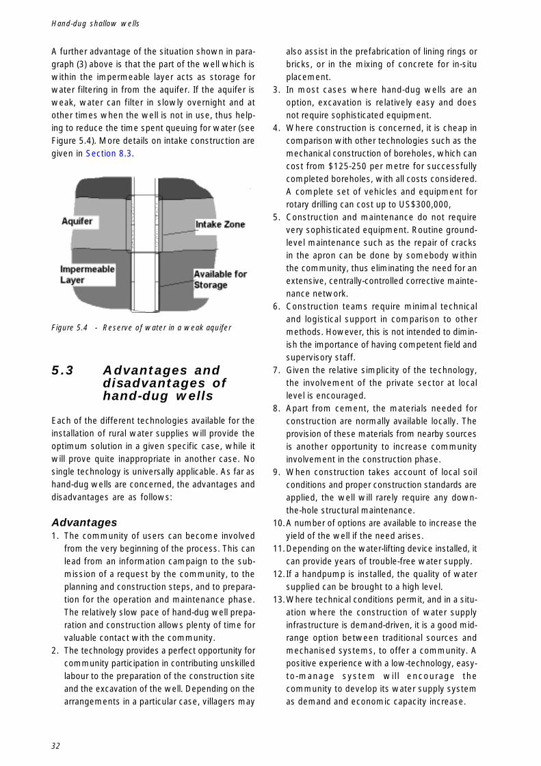
32
Hand-dug shallow wells
A further advantage of the situation shown in para-graph (3) above is that the part of the well which iswithin the impermeable layer acts as storage forwater filtering in from the aquifer. If the aquifer isweak, water can filter in slowly overnight and atother times when the well is not in use, thus help-ing to reduce the time spent queuing for water (seeFigure 5.4). More details on intake construction aregiven in Section 8.3.
also assist in the prefabrication of lining rings orbricks, or in the mixing of concrete for in-situplacement.
3. In most cases where hand-dug wells are anoption, excavation is relatively easy and doesnot require sophisticated equipment.
4. Where construction is concerned, it is cheap incomparison with other technologies such as themechanical construction of boreholes, which cancost from $125-250 per metre for successfullycompleted boreholes, with all costs considered.A complete set of vehicles and equipment forrotary drilling can cost up to US$300,000,
5. Construction and maintenance do not requirevery sophisticated equipment. Routine ground-level maintenance such as the repair of cracksin the apron can be done by somebody withinthe community, thus eliminating the need for anextensive, centrally-controlled corrective mainte-nance network.
6. Construction teams require minimal technicaland logistical support in comparison to othermethods. However, this is not intended to dimin-ish the importance of having competent field andsupervisory staff.
7. Given the relative simplicity of the technology,the involvement of the private sector at locallevel is encouraged.
8. Apart from cement, the materials needed forconstruction are normally available locally. Theprovision of these materials from nearby sourcesis another opportunity to increase communityinvolvement in the construction phase.
9. When construction takes account of local soilconditions and proper construction standards areapplied, the well will rarely require any down-the-hole structural maintenance.
10.A number of options are available to increase theyield of the well if the need arises.
11.Depending on the water-lifting device installed, itcan provide years of trouble-free water supply.
12.If a handpump is installed, the quality of watersupplied can be brought to a high level.
13.Where technical conditions permit, and in a situ-ation where the construction of water supplyinfrastructure is demand-driven, it is a good mid-range option between traditional sources andmechanised systems, to offer a community. Apositive experience with a low-technology, easy-to-manage system will encourage thecommunity to develop its water supply systemas demand and economic capacity increase.
Figure 5.4 - Reserve of water in a weak aquifer
5.3 Advantages anddisadvantages ofhand-dug wells
Each of the different technologies available for theinstallation of rural water supplies will provide theoptimum solution in a given specific case, while itwill prove quite inappropriate in another case. Nosingle technology is universally applicable. As far ashand-dug wells are concerned, the advantages anddisadvantages are as follows:
Advantages1. The community of users can become involved
from the very beginning of the process. This canlead from an information campaign to the sub-mission of a request by the community, to theplanning and construction steps, and to prepara-tion for the operation and maintenance phase.The relatively slow pace of hand-dug well prepa-ration and construction allows plenty of time forvaluable contact with the community.
2. The technology provides a perfect opportunity forcommunity participation in contributing unskilledlabour to the preparation of the construction siteand the excavation of the well. Depending on thearrangements in a particular case, villagers may

33
Principles of hand-dug wells
14.Wells can be excavated in harder soils wherehand-drilling is difficult.
15.A large-diameter, hand-dug well exposes moreof the aquifer, thereby allowing a greater volumeof water to flow into the well, and creates alarger reservoir for water storage.
16.In the case of a closed well, if the handpumpexperiences a serious breakdown, there is alter-native emergency access to water via theinspection cover.
17.While the construction phase may be longerthan with other technologies, the longer time willbe useful in assuring the acceptance of the newsystem by the villagers since the community willhave more time to witness the development and“arrival” of the new system.
18.Hand-dug wells are in many cases very similarin form to traditional water collection systems.As such, the technology can be readily acceptedby the community, and provides an ideal basisfor future development of the system (for exam-ple, from an open well to a covered well with ahandpump, and from there to a system with amotorised pump).
Disadvantages1. Community participation may be difficult due
to safety considerations (see Section 8.5). Exca-vating a well is a hazardous undertaking, evenin ideal conditions, and the work cannot bepassed lightly to inexperienced workers. If, onthe other hand, the work is given to a privatecontractor, he or she may not wish to be de-pendent on a supply of voluntary labour overwhich there is very little control, given the manydemands on the time of rural farming and fish-ing families.
2. Excavation can be dangerous for a number ofreasons. At depths of over 2 metres, access tothe well by those doing the excavation must besubject to strict safety controls. Also, in someareas, the process of excavation may releaseharmful gases.
3. During excavation, a method of keeping the wellpumped dry after reaching the water table isrequired. This will normally involve a motorisedpump, which in turn will require a power source.The capacity to dewater the well will limit theextent to which excavation can continue belowthe top of the water table.
4. The lowering of lining rings weighing up to 900kgcan be a dangerous operation.
5. Supply is greatly influenced by water table fluc-tuations.
6. Since most hand-dug wells exploit shallowaquifers, water in the well may be susceptible topollutants infiltrating from the surface.
7. In open hand-dug wells, the water can be con-taminated by mud, vegetation, bird and animaldroppings or even by rubbish thrown into thewell.
8. Again in an open well situation, the use of mul-tiple buckets and ropes can lead tocontamination of the water.
9. An open and unprotected well can be dangerousfor the users. Small children, especially, can fallin.
10.A programme of shallow well constructionneeds much more supervision capacity perperson served, since it is normally necessary tomake several visits to a construction site over aperiod of weeks during the construction phase.With a drilling programme, wells in one villagecould be completed with a single visit of a fewdays’ duration.

34
Hand-dug shallow wells
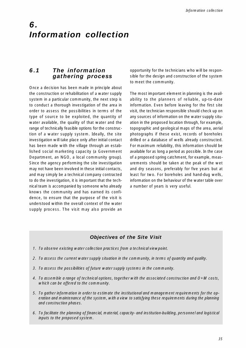
35
Information collection
6.Information collection
6.1 The informationgathering process
Once a decision has been made in principle aboutthe construction or rehabilitation of a water supplysystem in a particular community, the next step isto conduct a thorough investigation of the area inorder to assess the possibilities in terms of thetype of source to be exploited, the quantity ofwater available, the quality of that water and therange of technically feasible options for the construc-tion of a water supply system. Ideally, the siteinvestigation will take place only after initial contacthas been made with the village through an estab-lished social marketing capacity (a GovernmentDepartment, an NGO, a local community group).Since the agency performing the site investigationmay not have been involved in these initial contacts,and may simply be a technical company contractedto do the investigation, it is important that the tech-nical team is accompanied by someone who alreadyknows the community and has earned its confi-dence, to ensure that the purpose of the visit isunderstood within the overall context of the watersupply process. The visit may also provide an
opportunity for the technicians who will be respon-sible for the design and construction of the systemto meet the community.
The most important element in planning is the avail-ability to the planners of reliable, up-to-dateinformation. Even before leaving for the first sitevisit, the technician responsible should check up onany sources of information on the water supply situ-ation in the proposed location through, for example,topographic and geological maps of the area, aerialphotographs if these exist, records of boreholesdrilled or a database of wells already constructed.For maximum reliability, this information should beavailable for as long a period as possible. In the caseof a proposed spring catchment, for example, meas-urements should be taken at the peak of the wetand dry seasons, preferably for five years but atleast for two. For boreholes and hand-dug wells,information on the behaviour of the water table overa number of years is very useful.
Objectives of the Site Visit
1. To observe existing water collection practices from a technical viewpoint.
2. To assess the current water supply situation in the community, in terms of quantity and quality.
3. To assess the possibilities of future water supply systems in the community.
4. To assemble a range of technical options, together with the associated construction and O+M costs,which can be offered to the community.
5. To gather information in order to estimate the institutional and management requirements for the op-eration and maintenance of the system, with a view to satisfying these requirements during the planningand construction phases.
6. To facilitate the planning of financial, material, capacity- and institution-building, personnel and logisticalinputs to the proposed system.

36
Hand-dug shallow wells
Once the general information on the water situationhas been collected, (and an agreement has beenreached, in principle, among all participants in theprocess), the next step is to try to decide on thelocations for the proposed wells. The sanitary sur-vey of the site of any new well should show that itconforms to the guidelines as indicated in Section6.3. Information about the possible presence ofgroundwater at a given point is available from anumber of sources, in addition to the documenta-tion mentioned above:
Sources of information on the presence of shallow groundwater
1. Contact with villagers, especially with traditional well diggers. Members of the community will be ableto indicate areas liable to flooding, old water collection points etc. In addition, they can indicate sitesof cultural, historical or spiritual importance to the community, which may be out of bounds for wellconstruction.
2. Visits to existing water sources, whether rivers, springs, or “traditional” waterpoints, including sourcesthat have dried up temporarily or permanently.
3. Where a spring occurs at the foot of a slope, a waterpoint situated farther up the slope will more thanlikely yield water. Alternatively, if conditions and water quality permit, the spring itself may be captured.
4. The presence of certain types of vegetation indicates shallow groundwater. Vegetation such as bananaplants, bulrushes, sugar cane and date palms can indicate the presence of water, as well as providingan ideal dispersal area for spillage.
5. If the village is near a river, the flood plain of the river can provide a good location for a hand-dug well(always remaining above the seasonal flood level). However, alluvial deposits tend to be clayey in na-ture and therefore provide poor conditions for the flow of water through the aquifer. Alluvial depositsof high permeability may be found at places formerly on the outside of a bend in an old river alignment.A test borehole will give an indication of suitability in these cases.
6. Cliffs and other outcrops of rock may indicate a break in an aquifer from one side to the other.
7. Low-lying areas are more promising for well construction.
It is important to note the importance of physicalinvestigation in relation to checking possible wellsites. While it is essential to consult with the localcommunity, the opinions expressed by local peopleshould always be tested in some way by the sur-veyor. Persistence and consistency are importantfactors in the search for sources.

37
Information collection
6.2 Technical siteinvestigation
6.2.1 Testing methods andequipment
When visiting the proposed location for a well-dig-ging project, existing wells and waterpoints must bevisited and as much information as possible col-lected from local sources. When planning to workin an area for which reliable information is not read-ily available, it is advisable to drill a trial boreholeand conduct a yield test before committing re-sources to the construction of a waterpoint. Thepresence of groundwater can also be indicated bygeophysical tests involving electronic equipment,which may not be within the budget of many waterdevelopment agencies, and is generally more suitedto the sinking of deeper boreholes (over 25 metres).The work is specialist in nature and is outside thescope of this manual (see suggestions for furtherreading in Appendix 1). In any case, it is advisablethat, even when water is indicated by such amethod, a test drilling be done to ascertain the yieldof the aquifer.It is necessary to consider the economic aspectsof conducting tests prior to initiating constructionwork. For a large project involving the drilling ofboreholes with rotary or cable-tool equipment, it isadvisable to collect as much geophysical informa-tion as possible before signing a contract with adrilling firm. If the technology to be applied is rela-tively basic, such as driven or bored tube wells orhand-dug wells, and the scale of the project is small,it may be more efficient in the long run to start ex-cavating or drilling at carefully-chosen sites, withoutdoing any previous trial boreholes.If testing is to be carried out, the best time to doso is towards the end of the dry season, since agood result at this time will augur well for the pres-ence of water throughout the year. Essentially, thetest will consist of a trial borehole (recording thetype and thickness of strata encountered, the depthof the water table and thickness of the aquifer), andan associated yield test. The borehole may be de-veloped manually or using motorised equipment.The important factors are that strict guidelines befollowed in the recording of the material encounteredduring the drilling, and in the carrying out of the yieldtest afterwards. This information will be importantin the planning of any construction work.
6.2.1.1 Manually operated drillingequipment
This equipment is similar to that described inSection 4.3.2 on manually bored tube wells. It con-sists of a set of drill bits of various diameters, usually100mm and 70mm, attached to steel rods anddriven into the ground using a manually-turnedhandle. In favourable soils (loose sands with littlegravel and a low clay content), this equipment canbe used to a depth of 18 metres. In clays and rockystrata, the range is reduced to about 8-10 metres.Manually-operated equipment is cheap and easyto use and again provides an ideal opportunity forcommunity participation as villagers can assist inthe drilling. However, see Section 6.2.1.3.
6.2.1.2 Motorised drillingequipment
From an economic standpoint, motorised drillingequipment should only be considered if its use isessential to the success of a project. In the rangeof depths to which hand-dug wells are constructed,manual equipment will normally be sufficient. Whilemachine drills have the advantages of being capa-ble of achieving greater depths, and of completinga test borehole in a shorter time, the equipment iscostly and requires careful and skilled handling, inaddition to the need to maintain a more extensivestock of spare parts. Light motorised equipmentmay encounter problems in crystalline basementcomplexes (see below).
6.2.1.3 Problems in crystallinebasement complexes
Manually operated and light motorised drilling equip-ment do not work very well in crystalline basementcomplex areas where there is often a hard layerwhich has developed near to the surface. There mayalso be large unweathered fragments in the zonejust above the main bulk of unweathered rock.These fragments will probably stop a hand-drivendrill-bit and may lead to an under-estimation of thetrue depth of the weathered zone. The main prob-lem is that it is precisely in the area just above theunweathered rock that permeability is highest, andpromising well sites may be missed as a result.
In such areas, an economical alternative to the useof such equipment is to excavate by hand tothe dimensions of the proposed well. Instead ofusing concrete rings to line the excavation, timbershoring, supported by internal steel hoops, is used
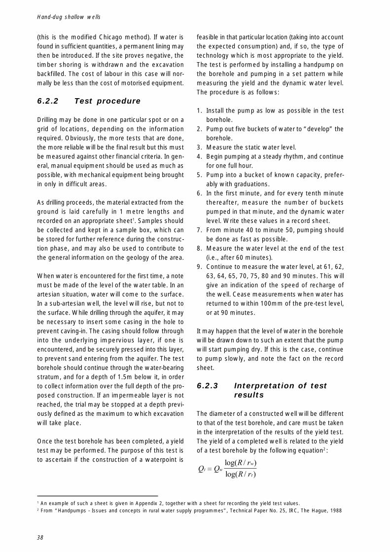
38
Hand-dug shallow wells
(this is the modified Chicago method). If water isfound in sufficient quantities, a permanent lining maythen be introduced. If the site proves negative, thetimber shoring is withdrawn and the excavationbackfilled. The cost of labour in this case will nor-mally be less than the cost of motorised equipment.
6.2.2 Test procedure
Drilling may be done in one particular spot or on agrid of locations, depending on the informationrequired. Obviously, the more tests that are done,the more reliable will be the final result but this mustbe measured against other financial criteria. In gen-eral, manual equipment should be used as much aspossible, with mechanical equipment being broughtin only in difficult areas.
As drilling proceeds, the material extracted from theground is laid carefully in 1 metre lengths andrecorded on an appropriate sheet1. Samples shouldbe collected and kept in a sample box, which canbe stored for further reference during the construc-tion phase, and may also be used to contribute tothe general information on the geology of the area.
When water is encountered for the first time, a notemust be made of the level of the water table. In anartesian situation, water will come to the surface.In a sub-artesian well, the level will rise, but not tothe surface. While drilling through the aquifer, it maybe necessary to insert some casing in the hole toprevent caving-in. The casing should follow throughinto the underlying impervious layer, if one isencountered, and be securely pressed into this layer,to prevent sand entering from the aquifer. The testborehole should continue through the water-bearingstratum, and for a depth of 1.5m below it, in orderto collect information over the full depth of the pro-posed construction. If an impermeable layer is notreached, the trial may be stopped at a depth previ-ously defined as the maximum to which excavationwill take place.
Once the test borehole has been completed, a yieldtest may be performed. The purpose of this test isto ascertain if the construction of a waterpoint is
feasible in that particular location (taking into accountthe expected consumption) and, if so, the type oftechnology which is most appropriate to the yield.The test is performed by installing a handpump onthe borehole and pumping in a set pattern whilemeasuring the yield and the dynamic water level.The procedure is as follows:
1. Install the pump as low as possible in the testborehole.
2. Pump out five buckets of water to “develop” theborehole.
3. Measure the static water level.4. Begin pumping at a steady rhythm, and continue
for one full hour.5. Pump into a bucket of known capacity, prefer-
ably with graduations.6. In the first minute, and for every tenth minute
thereafter, measure the number of bucketspumped in that minute, and the dynamic waterlevel. Write these values in a record sheet.
7. From minute 40 to minute 50, pumping shouldbe done as fast as possible.
8. Measure the water level at the end of the test(i.e., after 60 minutes).
9. Continue to measure the water level, at 61, 62,63, 64, 65, 70, 75, 80 and 90 minutes. This willgive an indication of the speed of recharge ofthe well. Cease measurements when water hasreturned to within 100mm of the pre-test level,or at 90 minutes.
It may happen that the level of water in the boreholewill be drawn down to such an extent that the pumpwill start pumping dry. If this is the case, continueto pump slowly, and note the fact on the recordsheet.
6.2.3 Interpretation of testresults
The diameter of a constructed well will be differentto that of the test borehole, and care must be takenin the interpretation of the results of the yield test.The yield of a completed well is related to the yieldof a test borehole by the following equation2 :
Q QR rR r
t ww
t�
log( / )log( / )
1 An example of such a sheet is given in Appendix 2, together with a sheet for recording the yield test values.2 From “Handpumps - Issues and concepts in rural water supply programmes”, Technical Paper No. 25, IRC, The Hague, 1988

39
Information collection
where:Qt = the yield of the test borehole, in litres per hourQw = the yield of the completed well, in litres per
hourR = the “radius of influence”, which has a typi-
cal value of 20mrw = the outside radius of the completed well,
including any gravel packing, in metresrt = the radius of the test borehole, in metres
Taking some typical dimensions, and assuming thatthe desired yield of a well will be 1000 litres perhour:Qw = 1000 l/hR = 20mrw = 0.75mrt = 0.05m
then the yield during the test should be 548 litresper hour. This calculation is quite theoretical, and inpractice the following values are adopted:
6.3 Guidelines forthe siting of awaterpoint
Even if a particular site gives very positive indica-tions for the presence of shallow groundwater,certain conditions must be fulfilled before continu-ing with a trial borehole or with actual construction.Internationally accepted guidelines for the locationof a waterpoint may be summarised under two setsof criteria, one general and one relating to the prox-imity of other structures or facilities, as follows.
1. General pointsThe proposed waterpoint or source should:
a) be above the flood level of any nearby riveror lake;
b) be in a location which allows the free accessof all users all year round. This refers tophysical access (i.e. that the pathway ispassable) but also to legal access. A right ofway must exist to the well.
c) (ideally) be within the specified distance fromthe intended users;
d) be in an area which will allow the rapiddispersal of spilt water;
e) be in a location where the level of the watertable is at a depth of at least 2m all yearround.
f) not be located in any other area liable toseasonal flooding;
g) not be located in any area where pesticidesor fertilisers are spread on crops;
h) not be in an area liable to erosion;i) not be in an area where the fluctuating fresh
water table is influenced by a saltwater table;j) not be in an area where the sinking of a well
will pierce the saltwater table;k) not be below, in terms of the direction of
groundwater flow, any source of pollutionsuch as a pit latrine, abattoir, dumping site,fertiliser or pesticide store etc. In addition, theminimum distances, in any other direction,to such sources of pollution, are given in thenext list.
yield in test borehole = 200 l/h or more -suitable for a hand-dugwell (large diameter)
yield in test borehole = 500 l/h or more -suitable for a borehole(small diameter)

40
Hand-dug shallow wells
2. Specific distances
Facility, Location Minimum distance fromor Building waterpoint in m
a)Communal dumping site 100b)Store for pesticides, 100
fertilisers or fuelsc)Cemetery 50d)Abattoir 50e)Dwelling house 10f) Pit latrine 30g)Animal pen 30h)Private (domestic) dumping site 30i) Large trees or any tree 20
with extensive root systemsj) Roads, airstrips, railway lines 20k)River or lake 20l) Laundry or washing slab 20
These criteria are represented graphically in Figure6.1. If these guidelines cannot be fulfilled, either bychoosing an already-appropriate site or by making
Figure 6-1 - Location of a Well
the necessary adjustments (for example, by theclosing down of a communal or private dumpingground or of a pit latrine), then another site shouldbe chosen. In the case where a dump, pit latrine orpesticide/fertiliser store is to be relocated to makeway for a waterpoint, sufficient time must beallowed for the existing pollutants to dissipate in theground, before beginning to use the water for humanconsumption. The water quality should be testedto ensure that all pollutants have been dispersed.In certain specific circumstances, the distance froma pit latrine may be reduced, but if there is any un-certainty about fulfilling these conditions, it isadvisable to comply with the 30m criterion givenabove.
Where pit latrines are in use, the bottom of thelatrine pit should be normally no less than 1m abovethe top of the aquifer.
In all cases, the local community must be fullyinvolved in the decision about the location ofwaterpoints.

41
Information collection
6.4 Making the decision
The decision to propose the construction of a hand-dug well in a particular location can be made oncethe following specific criteria have been met:
Criteria to Satisfy
1. The community has displayed a preference forand a willingness to accept the technology ofa hand-dug well system.
2. The community will be able to perform theexpected tasks of operation and maintenancein a sustainable manner
3. The community will be capable of making theexpected contribution to construction costs(where this criterion applies).
4. The local economy will be able to absorb theoperation and maintenance costs.
5. A survey indicates the presence ofgroundwater at a level of more than 3 metres(but less than the agreed maximum depth ofexcavation), in at least one aquifer of morethan 1 metre thickness.
6. A test on a 100mm trial borehole shows asuitable yield (see Section 6.2.2).
7. There are no geological conditions in the areawhich would render the construction of a hand-dug well inadvisable or unsafe.
If not satisfied, the following options are stillopen:
� The community may opt for an improvementof existing sources.
� Consider the basic improvement of existingwaterpoints.
� If the community cannot support the installa-tion of a handpump, propose a windlass &bucket system3.
� If the community cannot afford to have a newsystem constructed, propose the improve-ment of traditional sources, if possible.
� If it is the O+M of a handpump which is theobstacle, install a windlass & bucket systeminstead of the handpump.
� If the community still cannot meet O+Mcosts, propose the protection of existing tradi-tional sources, if possible. In cases, this maybe the ideal initial step in a gradual process ofimprovement in the supply system.
� If conditions permit, consider the sinking of adeeper borehole. In this case, the implicationsin terms of construction cost, and the O+Mcosts of a medium- or deep-well pump mustbe taken into account.
� If the yield is inadequate, consider extendingthe exposure of the aquifer by using radialdrains (see Section 13.1) or by drilling throughthe bottom of the well.
� If the yield is still inadequate, look for anothersite.
� Look for another, safer site.
3 For hygiene reasons, communal users of a windlass and bucket system should not be allowed to use individual buckets andropes.
42
Hand-dug shallow wells
The above list is intended as a general guideline, andlocal conditions and experiences will at all timestake precedence over the content shown. In particu-lar:1. With regard to point 3, if the community cannot
afford, or is not willing, to make the expectedcontribution to the most basic technical option,the decision to continue with the construction orimprovement of water systems is not technicalin nature. In this case, priorities must be set anda clear policy put in place to guide the project. Itmay be necessary to place greater emphasison the creation of awareness within the commu-nity with regard to the advantages of improvedwater supply.
2. For points 5 and 6, experience in a particulararea, and the size of the project in question, willdictate whether or not extensive surveying,including the sinking of trial boreholes, will benecessary before committing resources toconstruction.
3 For hygiene reasons, communal users of a wind-lass and bucket system should not be allowedto use individual buckets and ropes.
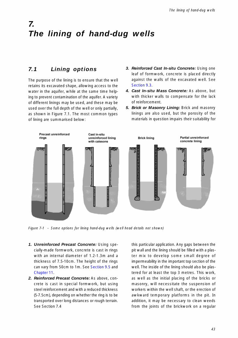
43
The lining of hand-dug wells
7.The lining of hand-dug wells
7.1 Lining options
The purpose of the lining is to ensure that the wellretains its excavated shape, allowing access to thewater in the aquifer, while at the same time help-ing to prevent contamination of the aquifer. A varietyof different linings may be used, and these may beused over the full depth of the well or only partially,as shown in Figure 7.1. The most common typesof lining are summarised below:
Figure 7-1 - Some options for lining hand-dug wells (well head details not shown)
1. Unreinforced Precast Concrete: Using spe-cially-made formwork, concrete is cast in ringswith an internal diameter of 1.2-1.3m and athickness of 7.5-10cm. The height of the ringscan vary from 50cm to 1m. See Section 9.5 andChapter 11.
2. Reinforced Precast Concrete: As above, con-crete is cast in special formwork, but usingsteel reinforcement and with a reduced thickness(5-7.5cm), depending on whether the ring is to betransported over long distances or rough terrain.See Section 7.4
3. Reinforced Cast In-situ Concrete: Using oneleaf of formwork, concrete is placed directlyagainst the walls of the excavated well. SeeSection 9.3.
4. Cast In-situ Mass Concrete: As above, butwith thicker walls to compensate for the lackof reinforcement.
5. Brick or Masonry Lining: Brick and masonrylinings are also used, but the porosity of thematerials in question impairs their suitability for
this particular application. Any gaps between thepit wall and the lining should be filled with a plas-ter mix to develop some small degree ofimpermeability in the important top section of thewell. The inside of the lining should also be plas-tered for at least the top 3 metres. This work,as well as the initial placing of the bricks ormasonry, will necessitate the suspension ofworkers within the well shaft, or the erection ofawkward temporary platforms in the pit. Inaddition, it may be necessary to clean weedsfrom the joints of the brickwork on a regular

44
Hand-dug shallow wells
basis. Because of these hygiene, constructionand maintenance factors, this method of lining isdiscouraged.
6. Other Lining Types: This manual concentrateson the construction of wells for the provision ofdrinking water, and as a result deals with liningmethods which are long-lasting and easy tokeep clean. In emergency situations, or wherethe water is not intended for human consump-tion, other lining materials can be used. Theseinclude timber and bamboo, as well as corru-gated iron or fibre-glass. These materials maynot be suitable in other cases due to considera-tions of hygiene or cost. If timber is to be thelining material, the excavation should be square,and the lining will be comprised of verticalplanks shored up at least every two metres. Splitbamboo poles may be used as vertical lining,with other split poles bent around as horizontalstrengthening. Corrugated iron sections havealso been used on occasion.
7.2 Concrete for use inwell lining
Concrete, mass or reinforced, is the most popularmaterial for well lining and consists of four ingredi-ents: cement, sand, gravel and water.� Cement for use in the concrete must be Ordinary
Portland and it must be clean, dry and less thansix months old. Cement which has hardenedwhile in storage should not be used.
� Sand (fine aggregate) should be river or quarrysand. It should be clean and free from silt and or-ganic matter.The use of beach sand is the subject of somedebate. A feasibility study (see reference inAppendix 1) has shown that concrete of a rea-sonable quality (with 78-90% of the strength ofconcrete made with river sand) can be madeusing beach sand. The two factors to take intoaccount when considering the use of beachsand are the particle size distribution and the saltcontent. A fine size distribution will result in aless workable concrete, which could lead tospaces in the finished product. With regard tosalt content, the maximum allowable valueexpressed in terms of the weight of cement ina mix is 1%. Also, with reinforced concrete, saltin the mix will attack the reinforcement bars.In general, local conditions and traditions will
indicate the advisability of using beach sand. Ifused, it should be sieved to give a particle sizedistribution similar to good river sand. As a rule,beach sand should not be used in concrete to beused with reinforcement.
� Coarse aggregate, or gravel, should be clean,hard and non-absorbent. Granite, quartzite, andhard limestones and sandstones produce goodaggregates.
� Water to be used in the mixing should be freshand clean. Sea water is not acceptable.
It is advisable to conduct an investigation in the areaof the planned waterpoints, well in advance of thecommencement of construction work, to ascertainthe availability of the necessary raw materials in therequired quality and quantities. Members of thecommunity may be asked to begin stockpiling sandand gravel, and even water, before the constructioncrew arrives on site.
For best results, the concrete should be mixedusing a machine. If this is not possible, mixing canbe done by hand but the quantity of cement in themix should be adjusted to take account of this. Handmixing must be done on a clean and level surface,and preferably on a concrete slab cast especially forthe purpose. For both hand- and machine-mixing,strict supervision and careful preparation and organi-sation of raw materials are necessary. Wherepossible, mixing and pouring should be done in ashady location. When dealing with pre-fabricatedlining rings, it should be borne in mind that thecompleted rings cannot be moved for 7 days aftercasting, so the location in which the prefabricationtakes place should be at least big enough to caterfor 7 days’ production of precast elements. Formachine-mixing, ensure an adequate supply of fuel.
Concrete for the normal (non-filtering) type oflining should be mixed in the proportions 1:2:4(cement:sand:gravel) with enough water added,slowly, to the mix to make it workable and easy toplace. As a general rule, the amount of water isusually 22 - 33 litres per 50kg of cement. For handmixing, the amount of cement should be increasedby 10%, and all dry ingredients should be mixedthoroughly before any water is added.
The most important factor in the preparation of theconcrete is good quality control. The recommendedproportions should always be observed and the

45
The lining of hand-dug wells
mixing area and all equipment should be kept clean.When pouring concrete, there should be no longdelays during a pour. Casting should take place inone smooth, uninterrupted process, with the concretebeing well compacted as pouring proceeds. If thesepointers are observed, the resulting concrete will beof a good quality and will be able to withstand thepredominantly compressive loads when in place. Itshould not be necessary to go to the trouble of pre-paring concrete cubes and performing crushingtests. In any case, the application of such a testdoes not take account of the curing applied to thefinished product, a factor which can invalidate thetest results.
Steel to be used in reinforcement should be mildsteel, and it should be clean and free from loosescale, rust, oil and any other material which wouldimpair the bonding process with the concrete. Thereinforcement cages should be tied together usingsuitable soft-iron wire.
7.3 Advantages anddisadvantages ofusing precastconcrete liningelements
The use of precast concrete lining rings presents anumber of advantages over other methods of wellconstruction, as listed below.
Advantages1. From the point of view of safety, the work of
pouring concrete is done at ground level, soworkers spend less time down the excavation.
2. Quality control is easier to perform and the con-sequences of sub-standard workmanship ormaterials can be avoided.
3. When elements are precast at the well site, itprovides an ideal opportunity for community par-ticipation, in the provision of raw materials andin the mixing, placing and curing of the concrete.This precasting may be done before the wellexcavation commences.
4. The use of precast rings in deepening an exist-ing well is straightforward. Also, a number oftelescoping rings may be installed at the bottomof a well during construction, overlapping withthe standard rings. If the water table falls overtime, or during a particularly dry period, the well
can be deepened without the need to constructor transport new rings, and the work can evenbe carried out by local well diggers.
5. The use of precast rings for deepening existingwells can be applied to other well types.
Disadvantages1. The rings are heavy and difficult to manoeuvre,
especially when lowering into the well.2. Once a number of rings have been placed, it is
difficult to rectify errors in vertical alignment.3. If precasting is done at a central location, trans-
port can be difficult and expensive, and canresult in damage to the precast elements.
4. The position of the filter rings is set at the begin-ning of excavation, and cannot be altered.
The weight disadvantage may be avoided by usingrings of 50cm or 75cm, though a 50cm ring will stillweigh 400kg. If the vertical alignment is checkedregularly and carefully during excavation, the needfor realignment will be reduced.
7.4 Precast reinforcedconcrete rings
When reinforcement is introduced into the liningrings, the strength of the concrete is increased andthe thickness (and thereby the weight) can conse-quently decrease, while the ring will still be ableto withstand the loadings imposed during transportand placement. When a ring is in place in a well,the loading on it is usually only compressive innature, either vertically from the weight of the ringsabove it or horizontally from the pressure of the sur-rounding soil and water. This horizontal compressiveloading will normally be more or less uniformaround the circumference of the well but, if it ceasesto be so, tensile forces can be applied to the ring.If the ring is thin enough (10cm is adequate),the inherent flexibility will be able to deal with theimbalance in horizontal forces. As a result, the mainadvantages of using reinforcement in lining ringsare due to the reduction in size, allowing for the useof less material and also making transport andplacement easier, since the ring can be up to 50%lighter than the unreinforced version.
The minimum thickness of the ring is dictated bythe necessity to provide adequate concrete cover tothe reinforcement bars. In a hand-dug well, 20mm
46
Hand-dug shallow wells
cover to the reinforcement is adequate, so rings of50mm thickness can be built, with a cage of 6mmreinforcement (see Appendix 3). The aggregate sizeshould be 13mm maximum, and the concrete well-compacted during the pour, in order to ensure thereare no gaps between the steel and the concrete.50mm should be taken as the minimum possiblethickness for a lining ring.
The introduction of reinforcement demands anextra skill in the precasting team, and brings in con-siderations of the cost of purchasing, transporting,cutting and bending the reinforcement and making itup into cages for placing in the formwork. Extra caremust be taken in the selection of coarse aggregate.Care must also be taken in placing the concrete toensure that the reinforcement is well covered.
When using reinforcement, the steel should first beput together in a cage and the formwork assembledaround it. Spacers (such as suitably sized pebbles,or plastic spacers made in various widths especiallyfor the purpose) should be used to ensure that thereinforcement is properly located in the ring. Whilepouring the concrete, the compaction of each layerwill be made more difficult by the narrowness of the
openings at the top of the formwork, and it may benecessary to use a mechanical vibrator applied tothe outside using a special fitting.
Steel reinforcing bars, locally available in most coun-tries, should be mild steel, and it should be clean,and free from loose scale, rust, oil and any othermaterial which would impair the bonding processwith the concrete. The reinforcement cages shouldbe tied together using suitable soft-iron wire.
The decision whether or not to use reinforcementwill be based on economic criteria and on the avail-ability of the necessary skills in the area in question.The possibility of purchasing suitable steel in thelocal market is also an important consideration.
Apart from the placing of the reinforcement, theprocedures for prefabricating a reinforced concretelining ring are exactly as those described for anunreinforced ring in Section 11.3.1. If a rebate is tobe cast in such a thin ring, great care must be takenin transport and placement, and, if transport takesplace over rough terrain, such a ring would only bea suitable option if it were to be cast alongside thewell site.

47
Hand-dug well construction procedures — General
8.Hand-dug well construction procedures —General
8.1 Introduction
The important considerations with regard to theoverall construction process are the participation ofthe community to the fullest possible extent, theassembly of the necessary equipment in good work-ing order, the proper layout of the well site,adherence to safety procedures (as detailed in Sec-tion 8.5) and the availability of the relevant surveyreport for consultation.
8.2 Equipment
The equipment needed will depend on the liningmethod adopted and the construction procedure tobe followed. The following list gives an indicationof the main items which should be considered whenplanning the provision of equipment:
1. Formwork: Either one or two leaves of eachform will be needed, depending on the lining pro-cedure. Details of possible formwork are givenin Section 11.2 and in Appendix 3.
2. A device for lowering materials and equip-ment into the well: The type of device usedwill depend on the lining method. For precastconcrete rings, a tripod with a block-and-tackleof 2.5 tonne capacity is recommended. A simi-lar capacity will be necessary if precastcaissons are to be placed in a well with a castin-situ shaft lining. If the intake is to be con-structed in-situ, the capacity may be reduced,since only shuttering and buckets of concretewill be lowered into the well.
3. A dewatering device: This will be necessaryat some stage, irrespective of the lining typeand the procedure adopted. When using amotorised pump, as will normally be the case,the arrangement should be such that the motoris permanently outside the well, to avoid thedangers of inhalation of exhaust fumes by those
down the well. Care should be taken that thecapacity of the pump is sufficient to keep thewater in the well at a safe level.
4. A method of lowering workers into the well:An important consideration is the provision of asafe method of entering and leaving the well,especially after the depth exceeds 2m. This isbest done by rigging up a type of “bosun’s chair”with a strong piece of wood and a rope (seeFigure 8.1). This can then be lowered into thewell using the tripod. On no account shouldworkers attempt to climb out and in using foot-and hand-holds in the sides of the well. Whendown the well, workers should wear protectivehelmets, and should at all times comply withrelevant health and safety guidelines.
8.3 Intake Construction
The principles of the intake part of a well were intro-duced in Section 5.2.4. In practice, the type of intakeconstructed will depend on the lining option selected,and on the construction sequence adopted. The pos-sible variations may be summarised as follows:
� The well is excavated and lined in-situ to the topof the water table. The intake lining is thenprefabricated and sunk, through continued exca-vation, into the aquifer. This procedure isdescribed in Sections 9.3 and 9.5
� The well is excavated to below the level of thewater table. A pump is used to keep the welldry while the intake is constructed in-situ. Thismethod is described in Section 9.4.
Figure 8-1 - Two Possible Designs for a Bosun’s Chair

48
Hand-dug shallow wells
� The well is excavated to the top of the watertable. A complete prefabricated lining is putin place, with porous elements positioned toeventually coincide with the aquifer. Furtherexcavation is done to allow the lining to settleinto the correct position. This procedure is shownin Section 9.5.
8.4 Site layout
The layout of the construction site should allow foreasy access to the well with the necessary mate-rials, for the easy and appropriate disposal of thesoil excavated from the well and for the rapid andsafe dispersal of the water from the dewateringphase. A typical site layout is shown in Figure 8.2.
Vital information with regard to the excavation of thewell is contained in the report from the test boreholeor boreholes drilled at the site. Other important in-formation will be available from previous work in thearea and from local knowledge of the groundwaterconditions. Without the gathering of all possible in-formation on the proposed site, construction workshould not begin.
Figure 8-2 - A Typical Site Layout
The above layout may be modified where concreteis being placed in-situ, or where precasting of liningelements is being done adjacent to the well site (seeFigure 11.1).

49
Hand-dug well construction procedures — General
8.5 Safety precautions
Shallow well construction can be a dangerousactivity, and some project managers may hesitateto allow unskilled or uninsured personnel down anexcavation. This may limit the degree of commu-nity participation possible, but it is better to err onthe side of safety in these cases.
In the excavation of hand-dug wells, the mostcommon causes of injury are sub-standard equip-ment, collapse of the well, and equipment ormaterials falling down the well. On occasion, theexcavation may liberate harmful gases which couldcause asphyxiation. The following precautions shouldbe taken at all times during excavation and construc-tion of a hand-dug well:� Ensure that all equipment is in good working
order, regularly maintained and checked, andreplaced when necessary.
� When workers are down the well, there shouldalways be somebody on the surface to attend tothem.
� The diggers should always be assured quickaccess to an emergency escape (by ladder,rope, etc.)
� Well diggers should enter and leave the well ina safe manner.
� Well diggers should always wear safety hel-mets, which should be replaced after anyimpacts.
� Ensure that no objects or people can fall into thewell. Provide guard rails and, at night, cover thewell or make sure that someone is on guard toprevent animals or people from falling in.
� Do not excavate greater than 5m without tempo-rarily or permanently securing the sides of theexcavation.
It is a good idea to provide temporary shoring at thetop 2m of the pit. This can be arranged with verti-cal planks, held in place with steel hoops andwedges. The top of the planks can be allowed toprotrude above the top of the pit, thus providing abarrier against people and materials falling into theexcavation. If it is found that the excavation needsto be supported below 2m, there are two options.Firstly, the timber shoring may be continued by theaddition of more planks and hoops. This is calledthe Modified Chicago Method. Alternatively, the firstof the lining rings may be placed and excavationmay continue as described in Section 12.2.

50
Hand-dug shallow wells

51
Examples of construction sequences
9.Examples of construction sequences
9.1 Introduction
The following sequences refer to the options for lin-ing and intake construction outlined in Section 8.3.For the purpose of describing the constructionsequence, we are assuming that the overlying strataat the well site are firm. There are particular prob-lems related to excavating in loose soils, and theseare treated in Section 12.2.
9.2 Location ofexcavation
Where possible, the well should be constructeddirectly over the site of a successful trial borehole.If a grid of trial boreholes was made, the well shouldbe located within the limits of the grid, close to orat the highest-yielding borehole. Before beginning theconstruction of the well, the technician responsibleshould consult the trial borehole report(s) in order tohave a good idea of the soil conditions which willbe encountered, the probable depth at which waterwill be reached, the thickness of the aquifer(s) and
the existence of impermeable strata below them.In cases where there is sufficient knowledge of thegroundwater regime in a particular area, it will notbe necessary to do a trial borehole. No constructionwork should go ahead without consulting those withlocal knowledge of the area.
Before excavation begins, it is necessary to definethe centre point and thereby the vertical axis of thewell. Since any mark at the centre of the well willbe affected by the excavation, the point is markedusing offset pegs, located on an extended diameterof the well, sufficiently far back from the expectededge of the excavation not to be affected by it, asshown in Figure 9.1. While excavation continues, thediameter of the well can be checked by means ofa length of stick suspended at the centre of the well,using the offset pegs to properly locate it. The stick,which should be suspended through its midpoint,should be 10cm greater in length than the outsidediameter of the lining rings. A plumb line can alsobe suspended from the centre point to check thevertical alignment of the excavation.
Figure 9-1 - Using Offset Pegs to Define the Centre of a Well

52
Hand-dug shallow wells
Locate the offset pegs securely using piecesof steel bar driven into the ground and embeddedin concrete. Ensure that the pegs are positionedso that they will not be affected by later excavationand construction activities. Excavation may nowcommence.
9.3 Cast in-situ concretelining withprefabricatedcaisson intake
One of the main advantages of this option is thatthe need to transport and/or lower heavy items downthe pit is reduced (but not altogether eliminated),since the main lining is not precast. However, it isnormally only the lining of the well above the levelof the water table which is cast in-situ. As withthe precast option, lining may be mass concrete orreinforced, and the procedure will generally be asgiven in the following summary. The subject hasbeen dealt with comprehensively in other publica-tions1 and it is not necessary to repeat the fulldetails here.
1. Excavate at the desired diameter down to adepth of 5m, or to the top of the water table,whichever occurs first. (Unless the soil is particu-larly stable, it is not advisable to excavate furtherwithout pouring the first lift of lining). The diam-eter of the excavation will be 15cm greater thanthe desired internal diameter of the finished wellshaft. Care must again be taken when centringand plumbing the excavation, since parts of thelining which are too thin will weaken the struc-ture while areas which are too thick will result ina waste of material.
After properly trimming the excavation, theshuttering may be placed for the first lift. In thisinstance, only one leaf of shuttering is used, andit is built up in a column from the bottom of theexcavation. The plumbing of the formwork isfacilitated by the placing of a 50cm “levelling”shutter at the bottom of the excavation.
The space between this shutter and the wall ofthe pit is filled with well-compacted soil and ver-tical reinforcement bars are embedded in it. Inthis way, the steel will be held in place duringthe pouring operation. Horizontal reinforcement,in the form of circular bars, is fixed to the verti-cal bars with soft steel wire.
1 See Watt, S.B. and Wood, W.E., Hand Dug Wells and their Construction, London, 2nd ed. 1979, ITDG
2. A 1m high shutter is now placed on top of the“levelling” shutter and fixed firmly into position.Concrete is poured up to the level of the top ofthis shutter.
3. At the top of this shutter, a triangular curb is cutinto the surrounding soil to a depth of 20cm. Thepurpose of this curb is to provide some purchasefor the lining in the walls of the excavation, tohelp to counter forces due to self-weight. Rein-forcement bars, with a hook at the outer end,are driven into the soil at the back of the curb,and the hook is fixed around both a vertical anda horizontal reinforcement bar.

53
Examples of construction sequences
4. Once the curb has been prepared, concrete isplaced in it by hand. Shuttering may be placedand the rest of the lift poured. At the top of thewell, reinforcement bars are left protruding fromthe top of the lining. These will later be bent overand incorporated into the construction of the well-head.
5. Once the first lift has been poured, the shutteringis left in place and excavation continues downfor a further 4.65 metres or until the water tableis reached. The depth of 4.65m is specifiedbecause of the already-existing depth of 50cmbelow the bottom of the first lift, which waspacked with soil to allow the setting-up of thereinforcement. The only access to the secondshutter, in order to pour concrete, is through thisgap, and it is not possible to install the shutteringflush with the end of the first lift. As a result, a15cm gap is allowed between the lifts, and thisis later filled in with blocks.
The soil which was used to position the first set ofreinforcing bars is removed, and the bars are usedto help to provide continuity of reinforcementthroughout the lining. The setting of a levelling shut-ter is repeated at the bottom of the second lift, andreinforcement is put in place.
6. The steps outlined above for the first lift arerepeated.
7. The 15cm gap between the lifts is now filled in.
8. The above steps are repeated until the watertable is reached.
9. The situation at this point is that excavationhas ceased at the level of the water table, andthe pit has been fully lined to this level. Itremains to continue the well into the water table.This is done by making a column of porousrings (caisson), placing it in position inside thelined shaft and sinking it in much the samemethod as that described for excavation in loosesoils in Section 12.2.
This method is more time-consuming in the con-struction phase than using precast lining rings. It ispossible to avoid problems with vertical alignment,since it is much easier to correct the alignment ofa steel shutter, before pouring any concrete, than avery heavy column of precast rings. However,especially during the second and subsequent lifts,it is necessary that work is done in places which

54
Hand-dug shallow wells
are accessible neither from the top nor from thebottom of the excavation, necessitating the frequentuse of a bosun’s chair as a working platform andnot merely as a method of reaching the bottom ofthe pit. The safety of workers must receive due con-sideration in this instance.
9.4 Concrete lining withbuilt in-situ intake
Using this method, excavation is first carried out tothe desired finished level of the well, using adewatering device to keep the well dry. The con-crete shaft lining may use precast or cast in-situelements, but the distinguishing feature of thismethod is the in-situ construction of the intake inits final position. Because the well is lined from thebottom up, it is a suitable method only in areaswhere the soil is stable, unless temporary shutteringis to be used. Using cast in-situ concrete lining, aprecast guiding ring is first placed in the bottom ofthe well. Formwork is placed on top of this ring andthe first of the cast in-situ rings is poured. After ithas hardened sufficiently, the formwork is removedand placed on top of this ring in turn. The processis repeated up to ground level. A more detailedsequence is given below.
1. Excavate the well to the desired finished level.Once the excavation passes below the watertable, a dewatering device must be used. Thediameter of the excavation must be 60cmgreater than the outside diameter of the welllining, to allow assembly and dismantling of theformwork inside the well.
2. If necessary (see Section 5.2.4) insert a baseplug of porous material.
3. Place a precast concrete guiding ring on thebottom of the well. This is a precast ring ofthe desired diameter and wall thickness (usually5 or 10cm). The purpose of placing this ring is toprovide a starting level for the first cast in-situring, so the guiding ring must be plumbed care-fully to avoid problems with vertical alignmentfurther up the well. Depending on the desiredarea of inflow into the intake (bottom, sides orboth), the guiding ring will be of solid or porousconcrete. For information on precasting liningrings, see Section 11.3.
4. Backfill the space between the sides of the ex-cavation and the guiding ring with 20mm gravel,as shown.
5. Clean off the top of the guiding ring, fix formworkand cast a filter ring on top of the guiding ring.
6. Repeat the previous two steps until the completedepth of the exposed aquifer has been lined withfilter rings.
7. Seal the top of the intake lining with concrete(1:2:3) as shown in the diagram.
8. The construction of the intake is now completeand the lining of the shaft may be completed.This is accomplished by placing formwork, pour-ing the concrete, allowing it to set and removingthe formwork. Above the level of the intake, thebackfilling between the excavation wall and thelining ring may be done with some of the exca-vated soil. The sequence is shown in thefollowing figure.
In this method, precast rings may also be used afterthe intake has been constructed. In such a case,the diameter of the excavation needs only to be20cm greater than the final outside diameter of thelining, since no formwork will be assembled insidethe well shaft.

55
Examples of construction sequences
9.5 Prefabricatedconcrete lining rings
The following sequence describes a typical excava-tion procedure in firm ground. Details of precastingof lining rings and other elements are given in Chap-ter 11.
1. Begin excavation, disposing of the excavatedmaterial so that it will not cause an obstructionlater. The diameter of the pit should be checkedregularly by using trimming rods (5cm shorterthan the desired diameter), suspended at theaxis of the well, which is defined using offsetpegs. For a well using 1.3m external diameterrings, the pit diameter should be 1.5m, so thetrimming rods are 1.45m long.
2. The trimming rods can be made of wood orsteel (reinforcement bar is suitable), and theyshould be fixed together at the centre looselyenough to allow them to swing open in the pit.
During the excavation, the trial borehole reportshould be on hand for consultation. An independ-ent record should be kept of the materialencountered during the well excavation, for thepurposes of comparison. The information maybe recorded on a form similar to that shown inAppendix 2.

56
Hand-dug shallow wells
As already mentioned, it may be advisable to puttemporary shuttering on the upper 2m of the pit.
3. When the water table is reached, level off thebottom of the well and stop excavating.
4. Set up the tripod with block-and-tackle over thecentre of the well. Bring a cutting ring of thedesired type to the top of the excavation andcarefully place it, cutting edge down, over twosecurely positioned steel pipes or some strongpieces of timber across the top of the hole.
5. Fix a strong rope (remember, the ring weighsaround 900kg) to the ring and to the chains of theblock-and-tackle. Lift the ring slowly and care-fully to allow removal of the pipes. Make surethat the ring is securely held, and that it hangsvertically.
7. Follow the same steps with enough rings tocome up to ground level, always checking thevertical alignment. The sequence of types of ringshould follow that suggested by the trial boreholereport, with filter rings placed to coincide withthe aquifer once excavation is complete.
Before each ring is placed, put a layer of mortarof 1 part cement to 3 parts sand on top of thepreceding ring.
6. Lower the ring slowly into the well and settle itin place on the bottom. Check the vertical align-ment.
8. Recommence excavation, using pumping equip-ment to keep the bottom of the well as dry aspossible (pump not shown). Ensure rapid disper-sal, in a direction away from the excavation, ofthe water being pumped out of the well.

57
Examples of construction sequences
9. When excavating now, work slowly from thecentre of the well out to the walls of the ring, andwork evenly around the well, otherwise the ringsmay go out of plumb. Ensure that the ringssettle uniformly within the well.
12.The construction is now complete and the fol-lowing steps are necessary to prepare the wellfor use:� The gap between the outer wall of the lining
rings and the walls of the pit must bebackfilled. This is important in the creation ofa sanitary well. Below 2m depth, sandshould be dropped into the gap and washedin with water, compacting it. From 2m to thesurface, the area should be opened up widerthan the gap and then backfilled using well-compacted soil. There will be no gap at thelevel of the filter rings since these will sinkwhile in contact with the aquifer.
� The level of the top of the last lining ring to beplaced must be at least 20cm above the sur-rounding ground, if the well is to be fitted with
10.As the rings sink down into the well, continueto place more on top, placing mortar in the joints.
11.Continue excavating until one of three situationsoccurs:a) the cutting ring has passed into the imperme-
able layer by at least 150cm and the filterrings are aligned with the aquifer. This is theideal outcome.
b) excavation has continued to a total depth of 15mwithout encountering an impermeable layer;
c) due to the influx of water into the excavation,the capacity of the pumping equipment tokeep the well clear is no longer sufficientto guarantee the safety of the workers in theexcavation.
In the case of (b) above, the well may be fin-ished off by placing a plug on the bottom (seeSection 5.2.4). In (c), the well should first bebackfilled to provide a safe working environment,and then a base plug fitted if necessary. In eithercase, the positioning of the filter rings mustcoincide with the aquifer.

58
Hand-dug shallow wells
a handpump, and 80cm, if the well is toremain open (see Section 10.1).
� A yield test should be performed on thecompleted well. This is useful for recordpurposes, and may also be used to confirm(or change) the decision on which type ofwater-lifting device should be fitted.
� The well must be disinfected (see Section10.2).
� If the well is to be fitted with a handpump, acover slab must be put in place and thehandpump installed.
� After sufficient time has elapsed to allow theground around the well to settle, an apronmust be constructed.
The foregoing procedure is based on excavating tothe water table before placing any lining rings. If acomprehensive and reliable site investigation hastaken place before construction, and if one can bereasonably sure of encountering water at a particu-lar depth, rings may be placed from the beginningof excavation in a manner similar to that describedin Section 12.2 for excavation in loose soils. Thishas the advantage of protecting the workers as theyprogress down the pit, but requires care in attend-ing to the vertical alignment of the shaft.

59
Concluding works
10.Concluding works
10.1 Finishing off aboveground
The height of the top of the well above the surround-ing ground will depend on whether or not the wellis to remain open. If it is, water will normally beextracted by each individual consumer, using buck-ets. The headwall must therefore be made highenough to prevent animals and small children fromfalling in, but low enough to facilitate the lifting outof buckets of water. The height by which the wellextends above the ground should also take accountof the type of lifting system to be installed and thelater construction of a protective apron around thewell.
If the well is to remain open, the top of the last ringput in place should be a minimum of 80cm abovethe general level of the surrounding ground, beforeany apron is constructed. If the well will be closed,this may be reduced to 20cm. Since the desiredheight above the ground may not be reached usingrings of 1m height, it is useful to be able to castrings of 50cm or 75cm for this purpose.
For record and maintenance purposes, it is usefulto assign a unique code to a completed well. Thiscode may be used during the operation and main-tenance phase to report a breakdown or to monitormaintenance inputs to the well and any water-lifting device fitted on it. The code can easily beincorporated into the apron, but the construction ofthe apron should not be started until the grounddisturbed by the excavation process has had timeto settle once more. In the meantime, the code canbe inscribed in the top ring or the cover slab, or itcan be kept in a safe place by a member of thecommunity.
10.2 Disinfection of thecompleted well
It is more than likely that contamination will haveentered the well during the construction phase.Before the well is used as a source of drinking water,this contamination must be removed. In this situa-tion, the fact that the consumers must wait anotherfew days before using what looks like a completedwell must be carefully explained as early as possi-ble during the supply process so as to avoidfrustration and disappointment.
The most widely available agent for disinfectionis chlorine, which can be purchased as ordinarycommercial bleaching powder or liquid bleach, or asHigh Test Hypochlorite (HTH) solution. The amountof available chlorine varies with the source in ques-tion, being approximately 70% in HTH, 35% inbleaching powder and 5% in liquid bleach.
The disinfection of a well takes place in two stages- disinfection of the walls of the shaft and disinfec-tion of the intake. To disinfect the shaft, mix 100gof bleaching powder (or the equivalent using anothersource of chlorine) in 10 litres of water, and use thissolution to scrub thoroughly the walls of the well.Any liquid remaining after the washing should bepoured into the well. Then proceed as follows:
1. Make up a solution using 100g of bleaching pow-der in 10 litres of water for each cubic metre ofwater held in the well, and pour it in to the well.
2. Begin pumping immediately, and pump untilthere is a distinct smell of chlorine from the wa-ter. If there is no pump, water may be removedquickly using a number of buckets at the sametime.
3. Wait one hour.4. Pump again until there is a distinct smell of
chlorine.5. Wait one hour.6. Repeat steps 4 & 5 on two more occasions.

60
Hand-dug shallow wells
7. Let the water in the well stand undisturbed for atleast 12 hours.
8. Pump to waste until there is no odour of chlo-rine.
10.3 Well apron
If the area around a well is allowed to become dirty,and waste and stagnant water is allowed to accu-mulate, it will become a source of infection forthe users. Standing in bare feet in stagnant wateror mud is a serious health risk in the tropics, andthe open water also provides an ideal breedingground for mosquitoes and other disease carriers.The idea of hygiene in water use must start at thecollection point, otherwise the possible benefits froman improved water supply will be lost.
The construction of an apron at the well-head isan important contribution to the general hygiene ina community. In addition to discouraging the accu-mulation of stagnant water at the surface, the apronwill help to prevent the contamination of the wellthrough the infiltration of dirty water back into theaquifer.
A typical apron is shown in Figure 10.1. The shape
of the apron is not as important as the capacityto drain water away from the well as quickly aspossible and ensure its dispersal in a hygienic man-ner. Where possible, the drain can lead to an areaof vegetation, such as banana plants. If this is notan option, a soakpit can be built.
Depending on the lining method used, the apron maybe connected to the well lining. When reinforcedcast in-situ concrete is used, reinforcement barsare left protruding, around the circumference of theshaft, for 1m above the top of the well lining. Thesebars are then bent over and incorporated into theapron. When using precast units, this is not possi-ble, unless holes are drilled in the lining ring. A moredetailed drawing of one type of apron is given inAppendix 3.
It is important that no construction of the aproncommences until the soil around the well, whichwas disturbed by the construction activities, has hadan opportunity to settle once more. While certainprocedures advise waiting at least six months toallow this to happen, especially if the apron is tobe constructed in mass concrete, this need mustbe balanced against health considerations relatingto the state of the area around the well head. Localexperience will again dictate the best approach.
Figure 10-1 - A Circular Apron, with a surface drain, for a 1.3m diameter well

61
Concluding works
10.4 Fencing
In addition to constructing an apron, it is a good ideato erect a fence around a waterpoint. This can bedone immediately after the construction of the wellis finished, and should enclose an area roughly 10mby 10m around the well. The advantages of fencingare that it serves to define quite clearly, for the wholecommunity, the area of the well and it keeps ani-mals away from the well-head. In cases it may benecessary to have a gateway to keep out smalleranimals such as pigs and goats.
The erection of fencing provides another ideal op-portunity for community participation. The fencingcan be made of suitable local materials such asbamboo. However, care must be taken that, afterthe initial construction with such materials, it willbe possible (both financially and in terms of man-agement) to arrange the periodic replacement whichwill be necessary. It may be better in the long termto opt for a more permanent type of fencing withwood, steel or wire. Even in these cases, somemaintenance will be necessary. Problems ofreplacement and repair can be avoided altogether,and a more environmentally friendly solution applied,by using a living hedge as fencing. Whatever typeof fencing is used, it is important that access bythe well users is guaranteed.
Figure 10-1 - A Well-protected waterpoint
10.5 Laundry slab
In many communities, the washing of clothes isan important social activity. Since the collection ofwater for washing clothes is a significant part of thedaily chores, it is convenient to locate a washingarea near to the water collection point. If thecommunity which has built a waterpoint so desires,a washing slab can be constructed. This can be doneat the same time as the well is being constructed,or it can be built together with the well apron.
In the construction of the washing area, it is impor-tant to take care that the grey water draining off theslab is not directed back to the well. The slab shouldbe constructed below the well, physically and withregard to the flow of water in the aquifer, and ata distance of at least 20m. The slab should beprovided with a drain and a soakpit.

62
Hand-dug shallow wells

63
Precast concrete elements for hand-dug wells
11.Precast concrete elements for hand-dugwells
This chapter deals with the prefabrication of liningrings and other elements used in constructing awell.
11.1 Introduction
The work of precasting the rings and other elementsof a well may take place close to the proposed well,at a central location in the community (where morethan one well is being built), or at a centralisedworkshop serving a number of separate locationsin a district. As already mentioned, the formeroptions provide good opportunities for communityparticipation, but this advantage may be outweighed
Figure 11-1 - Layout of area for precasting concrete rings
by logistical or economic considerations whichwould necessitate the operation of a centralisedprecasting yard. In this case, the problem of trans-porting the completed rings arises, while at thesame time the problems of transporting large vol-umes of cement, sand, gravel and water may bereduced.
Whatever the strategy adopted, the site forprecasting must be prepared and laid out in such away as to ensure an efficient output. Figure 11.1shows a typical arrangement which takes accountof easy access for delivery or raw materials andcollection of completed rings, and a logical flow ofwork from beginning to end.

64
Hand-dug shallow wells
11.2 Formwork andequipment
The most important piece of equipment is theformwork. To allow frequent re-use, it should be ofrobust construction and preferably be made of steel.Dimensions may vary from country to country, andthose adopted in this manual, with a standard heightof 1m, a 1.1m internal diameter and a thickness of10cm, (see below and Appendix 3) serve merely asa guide. In addition to making rings of the standardheight, it is also useful to have formwork for mak-ing rings of 50cm and 75cm. These are used at thetop of the well, in order to finish off the lining at thespecified distance above the surrounding ground.
Since it is necessary during the excavation phasefor work to be done while standing within a ring,the diameter should allow one person to work withease and this is normally the limiting factor fordimensioning the ring. Typical formwork used for astandard ring is shown in the photographs.
The use of a concrete mixer is advisable in ensur-ing uniformity of mix and a smooth supply ofconcrete while the pour is in progress. Wheelbar-rows or strong buckets can be used to transport theconcrete for placing, while some 1.5m lengths of10mm reinforcement bar can be used to rod theconcrete to ensure compaction. It is important tohave a steel plate or some plastic sheeting to placeunderneath the formwork while the concrete is be-ing poured, though if this is not available, emptycement bags can be used. In any case, castingshould be done on a level concrete slab. Heavy plas-tic sheeting is also very useful in the curing process.
11.3 Prefabricatedconcrete lining rings
11.3.1 Standard ring
This section deals with the casting of a typicalunreinforced lining ring. Additional considerationswith regard to reinforced rings are given in Section7.4. The following is a typical procedure.
1. Ensure that the formwork is clean. Apply a thincoating of lubricant (such as coconut oil), to thesurfaces of the mould which will be in contactwith concrete. This will facilitate the removal ofthe formwork afterwards. Place the preparedformwork on a sheet of plastic or metal, on levelground. Ensure that the inside and outsideleaves are properly spaced.
Photograph 11-1 - Inner and outer formwork,dismantled
The outer shell of the formwork consists of twosemi-circular pieces of steel plate, with three chan-nel section stiffeners spaced evenly from top tobottom. At the ends of each section, perforatedsteel strips are affixed which allow the bolting of thesections together to form a cylinder 1m deep withan internal diameter of 1.3m.
The inner part of the formwork is an almost-complete cylinder with an external diameter of 1.1m,stiffened in this case on the inside surface, and withone removable section to facilitate striking of theformwork after pouring. The same fixing detailusing perforated strips and bolts is employed. Theinner leaf is also fitted with a ‘handle’ to allow itsremoval.
Photograph 11-2 - Formwork assembled and readyfor use
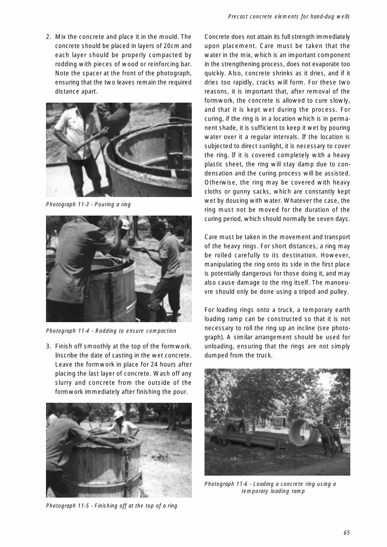
65
Precast concrete elements for hand-dug wells
2. Mix the concrete and place it in the mould. Theconcrete should be placed in layers of 20cm andeach layer should be properly compacted byrodding with pieces of wood or reinforcing bar.Note the spacer at the front of the photograph,ensuring that the two leaves remain the requireddistance apart.
Concrete does not attain its full strength immediatelyupon placement. Care must be taken that thewater in the mix, which is an important componentin the strengthening process, does not evaporate tooquickly. Also, concrete shrinks as it dries, and if itdries too rapidly, cracks will form. For these tworeasons, it is important that, after removal of theformwork, the concrete is allowed to cure slowly,and that it is kept wet during the process. Forcuring, if the ring is in a location which is in perma-nent shade, it is sufficient to keep it wet by pouringwater over it a regular intervals. If the location issubjected to direct sunlight, it is necessary to coverthe ring. If it is covered completely with a heavyplastic sheet, the ring will stay damp due to con-densation and the curing process will be assisted.Otherwise, the ring may be covered with heavycloths or gunny sacks, which are constantly keptwet by dousing with water. Whatever the case, thering must not be moved for the duration of thecuring period, which should normally be seven days.
Care must be taken in the movement and transportof the heavy rings. For short distances, a ring maybe rolled carefully to its destination. However,manipulating the ring onto its side in the first placeis potentially dangerous for those doing it, and mayalso cause damage to the ring itself. The manoeu-vre should only be done using a tripod and pulley.
For loading rings onto a truck, a temporary earthloading ramp can be constructed so that it is notnecessary to roll the ring up an incline (see photo-graph). A similar arrangement should be used forunloading, ensuring that the rings are not simplydumped from the truck.
3. Finish off smoothly at the top of the formwork.Inscribe the date of casting in the wet concrete.Leave the formwork in place for 24 hours afterplacing the last layer of concrete. Wash off anyslurry and concrete from the outside of theformwork immediately after finishing the pour.
Photograph 11-6 - Loading a concrete ring using atemporary loading ramp
Photograph 11-4 - Rodding to ensure compaction
Photograph 11-3 - Pouring a ring
Photograph 11-5 - Finishing off at the top of a ring

66
Hand-dug shallow wells
11.3.2 Filter ring
Figure 11-2 - A Filter ring (dimensions in cm)
Photograph 11-7 - A completed filter ring
Filter rings are placed at the depth of the well wherethe aquifer is exposed, and are designed to allowwater to seep into the well while avoiding the infil-tration of sand. A ring is cast of the same height,diameter and thickness as the standard ring, but themiddle 50cm of concrete is made in a special mixto allow water from the aquifer to enter the well.This mix reduces the amount of sand and, insteadof using the normal coarse aggregate, uses gravelwith a maximum size of 20mm. If this is not im-mediately available, the coarse aggregate shouldbe sieved to provide it. The mix is then made inthe proportions of 1:4 (cement:gravel). Because ofthis special layer, the filter ring will be considerablyweaker than the standard ring and greater caremust be taken during transport and placement.Compaction of the concrete cannot be done using
rods in this case, since the three layers wouldbecome mixed up. During pouring, the outside andinside walls of the formwork should be tapped witha hammer to ensure compaction.
11.3.3 Cutting (Leading) ring
The sinking of the well can be eased if the first ringto be placed in the hole has a sharper leading edge.This can be achieved by using a trowel to bevel thetop of a ring soon after the concrete has been placed(when it is soft enough to manipulate but sufficientlyhard to hold its shape). The bevel for a 10cm thickring has the dimensions shown in Figure 11.3. Twoimportant points must be noted here. Firstly, thecutting edge will be formed at the top of a ring, justas the initial set is taking place, so it must be turnedover before it can be used. Secondly, if the ring isreinforced, the cutting out of the bevel must notexpose the steel, and an allowance must be madefor the bevel in the placing of the reinforcement.
Figure 11-3 - Dimensions (in cm) for the bevelled edgeof a cutting ring
Inside faceof ring
10
7 3
10

67
Precast concrete elements for hand-dug wells
5 5
5
11.3.4 Rings with rebate
Figure 11-4 - Dimensions (in cm) of rebates forstandard ring
Photograph 11-8 - Rebate rings in position, awaitingassembly of formwork
For a 10cm ring, these rebates would be as shownin Figure 11.4 The rebates are cast by inserting aspecial metal ring at the bottom of the formworkbefore pouring, as shown in the photograph below,and fitting a corresponding ring at the top. Whenusing rings with rebates, care must be taken that aring is properly oriented before lowering it in thehole. Since the edges of rebated rings are thinner,more care must be exercised in transport and plac-ing. Dimensions for the rebate base and ring aregiven in Appendix 3.
11.3.5 Extension (telescoping)rings
In special cases where an existing well needs tobe deepened due to a general lowering of the watertable, rings are cast with a diameter which allowsthem to be lowered through the standard rings.These “telescoping” rings (see Figure 11.5) have atypical internal diameter of 85cm with a wall thick-ness of 7.5cm. This gives an overall outside
Figure 11-5 - Telescoping (extension) ring for a 1.1minternal dia. well (filter type shown)
In general, the main load on a lining ring will be self-weight and the weight of any rings above it. Lateralforces from soil and water pressure will more or lesscancel out around the circumference of the well. Ifit is expected that some lateral movement couldtake place, or if it is felt necessary to prevent ringsfrom moving in relation to each other during theexcavation and placement process, it is useful tocast rebates at the top and bottom of each ring. Byeliminating the movement of one ring relative toanother, the inclusion of rebates also ensures thatthe mortar seal between rings is kept intact, therebypreserving a seal around the well shaft and reduc-ing the risk of contamination by the infiltration ofpollutants.
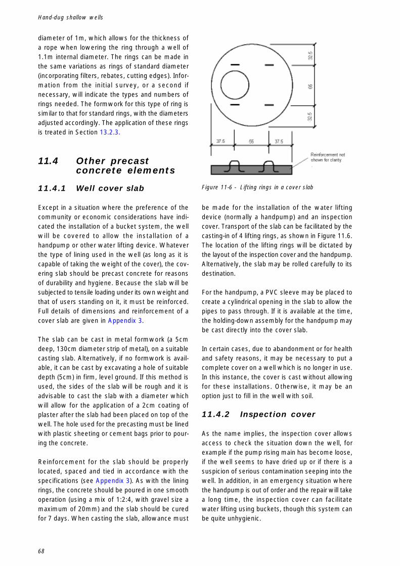
68
Hand-dug shallow wells
diameter of 1m, which allows for the thickness ofa rope when lowering the ring through a well of1.1m internal diameter. The rings can be made inthe same variations as rings of standard diameter(incorporating filters, rebates, cutting edges). Infor-mation from the initial survey, or a second ifnecessary, will indicate the types and numbers ofrings needed. The formwork for this type of ring issimilar to that for standard rings, with the diametersadjusted accordingly. The application of these ringsis treated in Section 13.2.3.
11.4 Other precastconcrete elements
11.4.1 Well cover slab
Except in a situation where the preference of thecommunity or economic considerations have indi-cated the installation of a bucket system, the wellwill be covered to allow the installation of ahandpump or other water lifting device. Whateverthe type of lining used in the well (as long as it iscapable of taking the weight of the cover), the cov-ering slab should be precast concrete for reasonsof durability and hygiene. Because the slab will besubjected to tensile loading under its own weight andthat of users standing on it, it must be reinforced.Full details of dimensions and reinforcement of acover slab are given in Appendix 3.
The slab can be cast in metal formwork (a 5cmdeep, 130cm diameter strip of metal), on a suitablecasting slab. Alternatively, if no formwork is avail-able, it can be cast by excavating a hole of suitabledepth (5cm) in firm, level ground. If this method isused, the sides of the slab will be rough and it isadvisable to cast the slab with a diameter whichwill allow for the application of a 2cm coating ofplaster after the slab had been placed on top of thewell. The hole used for the precasting must be linedwith plastic sheeting or cement bags prior to pour-ing the concrete.
Reinforcement for the slab should be properlylocated, spaced and tied in accordance with thespecifications (see Appendix 3). As with the liningrings, the concrete should be poured in one smoothoperation (using a mix of 1:2:4, with gravel size amaximum of 20mm) and the slab should be curedfor 7 days. When casting the slab, allowance must
Figure 11-6 - Lifting rings in a cover slab
be made for the installation of the water liftingdevice (normally a handpump) and an inspectioncover. Transport of the slab can be facilitated by thecasting-in of 4 lifting rings, as shown in Figure 11.6.The location of the lifting rings will be dictated bythe layout of the inspection cover and the handpump.Alternatively, the slab may be rolled carefully to itsdestination.
For the handpump, a PVC sleeve may be placed tocreate a cylindrical opening in the slab to allow thepipes to pass through. If it is available at the time,the holding-down assembly for the handpump maybe cast directly into the cover slab.
In certain cases, due to abandonment or for healthand safety reasons, it may be necessary to put acomplete cover on a well which is no longer in use.In this instance, the cover is cast without allowingfor these installations. Otherwise, it may be anoption just to fill in the well with soil.
11.4.2 Inspection cover
As the name implies, the inspection cover allowsaccess to check the situation down the well, forexample if the pump rising main has become loose,if the well seems to have dried up or if there is asuspicion of serious contamination seeping into thewell. In addition, in an emergency situation wherethe handpump is out of order and the repair will takea long time, the inspection cover can facilitatewater lifting using buckets, though this system canbe quite unhygienic.
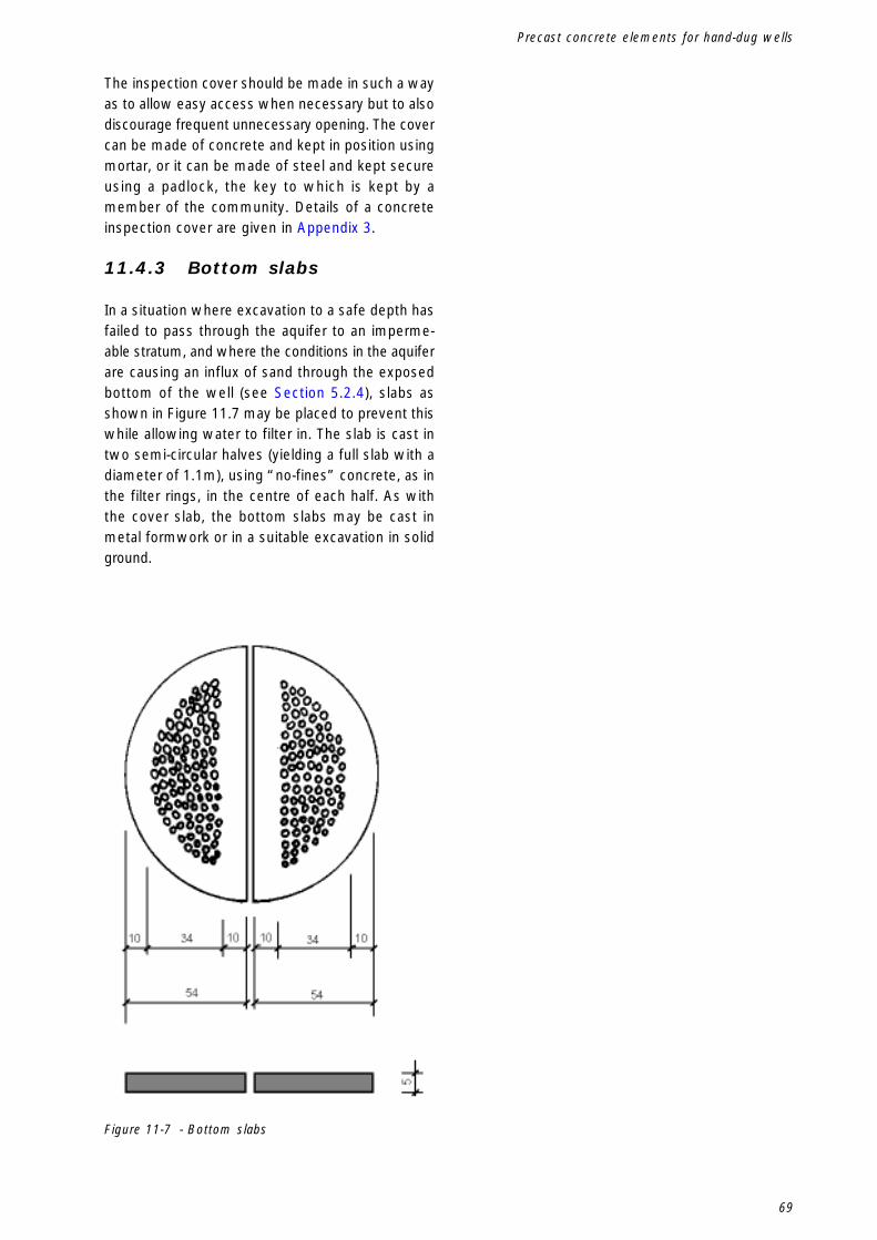
69
Precast concrete elements for hand-dug wells
The inspection cover should be made in such a wayas to allow easy access when necessary but to alsodiscourage frequent unnecessary opening. The covercan be made of concrete and kept in position usingmortar, or it can be made of steel and kept secureusing a padlock, the key to which is kept by amember of the community. Details of a concreteinspection cover are given in Appendix 3.
11.4.3 Bottom slabs
In a situation where excavation to a safe depth hasfailed to pass through the aquifer to an imperme-able stratum, and where the conditions in the aquiferare causing an influx of sand through the exposedbottom of the well (see Section 5.2.4), slabs asshown in Figure 11.7 may be placed to prevent thiswhile allowing water to filter in. The slab is cast intwo semi-circular halves (yielding a full slab with adiameter of 1.1m), using “no-fines” concrete, as inthe filter rings, in the centre of each half. As withthe cover slab, the bottom slabs may be cast inmetal formwork or in a suitable excavation in solidground.
Figure 11-7 - Bottom slabs

70
Hand-dug shallow wells

71
Common problems encountered in well digging
12.Common problems
12.1 Introduction
This chapter details some common problemsencountered in the construction of hand-dug wells.
12.2 Excavation in loosesoils
Unlike firm soils, where the sides of a pit will moreor less retain their shape during excavation, loosesoils may assume an angle of repose of 30° or less.In such a situation, the construction of a hand-dugwell would involve an enormous amount of extraexcavation. Local experience and/or a site investi-gation should show whether a hand-drilled boreholeor a tube well would be a better option. If this isnot the case, and it is decided to go ahead with ahand-dug well, the use of a cast in-situ lining willnot be feasible.
The first excavation is done only to the depth of onelining ring, and the cutting ring is then placed in thehole (Figure 12.1). Excavation continues, with extrarings being placed at the top as the column of ringsdrops down the well under the force of its ownweight.
Figure 12-1 - Excavating in Loose Soils
A dangerous situation can arise when the wet soilis so loose that the imposition of an extra load on itcauses it to become “quick”. If the well is beingpumped dry to allow excavation, the difference inwater level between the inside and the outside ofthe rings will cause water, sometimes carryingsand, to flow quickly in under the bottom of thecutting ring. The sand can infiltrate so quickly thatexcavation is pointless and the rings will settle nofurther. Even placing further rings on top to increasethe weight will not resolve this problem. Carefulconsideration of the test borehole results and pro-files is necessary before committing resources towhat could become an expensive failure.

72
Hand-dug shallow wells
12.3 Loss of verticalalignment
If the material being excavated is composed of dif-ferent inclined layers, there may be some differentialsettlement of the lining rings, leading to a loss ofvertical alignment. In this case, as shown in Figure12.2, the mis-alignment is compensated for byexcavating first under the lower side of the rings,and secondly under the higher side. Needless tosay, this must be done very slowly and very care-fully. The dangers and problems involved in theresolution of such a situation are such that strictattention should be paid to the regular and frequentmonitoring of vertical alignment throughout theexcavation phase, in order to avoid the need for dan-gerous remedial measures.
Figure 12-2 - Correcting Loss of Vertical Alignment(angle of mis-alignment exaggerated)
12.4 Arrested descent oflining rings
In certain soils, usually unconsolidated, it can hap-pen that the column of lining rings will not descendunder its own weight. While taking care not to pre-cipitate a “quick” situation as described in theprevious section, there are a number of options:� increase the weight of the column by adding one
or two rings at the top;� lubricate the soil in contact with the rings already
in place by pouring water down between the pitwall and the rings;
� as a final option, it may be possible to continuethe excavation using the smaller diametertelescoping extension rings.

73
Low-yield wells
13.Low-yield wells
13.1 New wells
In a situation where the only option for water sup-ply open to a community is a very weak or verythin aquifer, the volume of water captured can beincreased by increasing the area of aquifer exposed.Sometimes, the use of a large diameter well suchas those described in the foregoing chapters is notsufficient, and other methods have to be used. Inthe case of a new well where the top of the aquiferis at least 2m below ground level, the desiredincrease in yield can be achieved by creating a largecatchment filter in the aquifer. Since this involves
Figure 13-1 - Improving the Yield of a New Well (see also Fig. 13-2)
digging down from the surface, it is not suitable fora situation where the aquifer is very deep, as thiswould involve a tremendous amount of excavation.However, consideration of the danger of contami-nation demands that the aquifer must be at least2m below ground level.
The catchment filter, made up of suitable gravelaggregate (minimum 40mm) should be placed totake advantage of the natural flow of water in theaquifer, as shown in Figure 13.1. It should coincideexactly with the aquifer, and should be sealed ontop with a 3cm layer of concrete.

74
Hand-dug shallow wells
A filter ring is positioned at the level of the aquifer,with at least one, and preferably two, standardlining rings underneath it, in the impermeable layer,to serve as a reservoir. Care must be taken duringexcavation not to dig through the bottom of imper-meable layer, a situation which could allow thestored water to drain away. Consideration should begiven to sealing the bottom of the reservoir if sucha situation if feared.
It is clear that this option involves a much greateramount of work than the normal hand-dug wellconstruction. In addition, there is the ever-presentdanger that the aquifer will “escape”, as canhappen with normal spring catchments. As a result,the option cannot guarantee a long-term supply ofwater. Before committing resources to this type ofconstruction, it must be clear that the communityhas no other option.
13.2 Improving the yieldof existing wells
13.2.1 Introduction
When the yield of an existing well drops, or ceasesaltogether, there may be a number of options for con-tinuing to use the same waterpoint. The particularoption to be chosen will depend on whether theproblem of the reduced yield is a consequence of alowering of the level of the water table or a decreasein the yield of the aquifer. In one instance, theintake of the well must be extended to a greaterdepth, while in the other the exposed area of theaquifer must be increased in a horizontal direction.
Figure 13-2 - Section A-A from Figure 13-1
Before any work is done, it is essential to do a trialborehole, either through the bottom of the well orimmediately beside it, with the former being clearlythe better option. The trial borehole and yield testare conducted in exactly the same manner asdescribed in Section 6.2.2.
13.2.2 Horizontal extension ofwell
Two common methods are shown in the diagramsbelow, involving the construction of tunnels or theinsertion of perforated pipes through the walls of thewell. Of the two methods, the former is the moredifficult and potentially more dangerous.
Figure 13-3 - Horizontal extension of Hand-dug Well
13.2.3 Vertical extension of well
In this case, there are two possibilities. If the trialborehole indicates a suitable yield, in either theexisting or a lower aquifer, the best option is tomanually drill a borehole through the bottom ofthe well. This method is not suitable for wells fittedwith buckets or other non-pumping systems since,unless the aquifer into which the borehole is drilledis artesian in nature, the level of water in the wellwill not increase. If the well has been fitted with ahandpump, the pump is simply re-installed with thefoot-valve at a lower depth.
In most cases, since hand-dug wells exploitunconfined aquifers, the best option will be to usetelescoping rings as illustrated in Section 11.3.5 (seeFigure 13.4 below). It is not viable simply to con-tinue excavating under the existing cutting ring andplace new rings on top, since surrounding soil willhave settled firmly against the existing rings, andthe topmost of the rings is bonded to the superstruc-ture. Also, the configuration of solid and filter ringsmight not suit the new aquifer to be exposed in thedeepened part of the well.

75
Low-yield wells
As the figure shows, there are three situations inwhich telescoping extension rings may be em-ployed. In (a), the well was constructed in anexisting aquifer, and construction was halted beforereaching an impermeable layer. Later, the watertable dropped, making the yield of the well unsatis-factory. A trial borehole done at the bottom of thewell during the dry season showed a continuationof the aquifer, so two extension rings were placedin the well.
In (b), the original well reached an impermeable layerand construction was halted. When the yielddropped, a further survey showed the presence ofa second aquifer below the impermeable stratum,so the well was extended to exploit it. Note that thewater level in this case will depend on whether ornot there is water in the first aquifer.
In case (c), a second survey did not show thepresence of further aquifers, so two standard (non-filtering) extension rings were introducedin order to increase the storage capacity of the well.This is a useful option when water collection is con-centrated at certain peak times during the day.
Figure 13-4 - Extending a Well using Telescoping Rings
The excavation and construction techniques will besimilar to those indicated for a normal well. In allcases, it is advisable that there be a degree of over-lap between the original rings and the extension ringsand that any gap between the rings be properlysealed with concrete, in order to prevent the infil-tration of material into the well.

76
Hand-dug shallow wells

77
Management, operation and maintenance
14.Management, operation and maintenance
14.1 Introduction
The completion of a hand-dug well, and the conse-quent supply of water to the community, is the endonly of the construction phase. The most importantphase in the life of the system is just beginning.Experience with capital-intensive, supply-driven pro-grammes has shown the need to pay due attentionto preparations for the management, operation andmaintenance of the completed system. If this needis not recognised and addressed, the chances arethat further capital investment, in the form of majorrepairs or rehabilitation, or even the construction ofa new system, will be necessary before long. Theoperation, maintenance and management of a wa-ter supply may be centralised or decentralised, orany mixture of the two options, depending on theparticular situation, but it would be foolish to neglect,when planning these activities, the tremendous re-source available in the community itself. It has beenstressed throughout this manual that one of the keyaspects in the long-term sustainability of any watersupply system is the full and enthusiastic involve-ment of the community in all phases (includingoperation, maintenance and management) of thewater supply process. In institutional terms, this isonly logical, since most water authorities or watersupply organisations in the developing world have,at best, sufficient resources only for the planning andconstruction phases. But an increase in construc-tion activities implies an increase in the need formanagement of completed systems and it is herethat the community has the most vital role to play.
In many cases, the community will not be able tofulfil its role in the management of a system with-out adequate prior training. This must be given inboth the technical and management spheres, andclearly one must complement the other and bothmust be specific to the situation in hand. Neither isthis training an activity which can be undertaken inthe final days of a construction phase. During theplanning process, once the proposals and decisionshave been made about the type of technology to be
implemented and the related management plan, keypersons in the community must be identified whowill be responsible for various aspects of themanagement of the system.
At least two people in the community must becapable of maintaining the handpump or otherwater lifting device. The pump should be introducedto the community as early as possible in the proc-ess and training initiated. Appropriate tools must beprovided, and the installation of the pump providesan ideal opportunity for a final maintenance class.The community will also require some person withthe capacity to do minor structural repairs. In mostcommunities, finding such a person is not a prob-lem, and the training is more concerned withidentification of the need to repair, and the value ofpreventive maintenance, than with imparting specificworking skills. It is an advantage if the person tobe responsible for future structural repairs worksdirectly with the technical team during the mainconstruction phase.
The financing of the activities referred to in theprevious paragraph is quite open to whatever insti-tutional set-up applies in a particular case. The workmay be done voluntarily by members of the com-munity; the person responsible for maintenanceand management may be a water vendor who signsa contract for the franchise on a given well; main-tenance work may be done by a private individualwho then invoices the work to the village. If thecommunity is required to pay for water, in orderto create a fund for maintenance, or in a water-vending system, rules must be laid down about thelevel of payment, conditions for exemption, penal-ties for non-payment, etc. It was already pointed outin Chapter 2 that a comprehensive water policy cansmooth out the definition and introduction of suchpractices, but the capacity must also be in place tobring these ideas to the villagers and to impart themin a way that ensures a full understanding andacceptance, and which develops in the communitythe capacity to manage the new system.

78
Hand-dug shallow wells
A further advantage of community involvement inthe management of a water supply system, fromthe point of view of the water authority, is the avail-ability of a ready-made monitoring network. With thelack of resources faced by many water authorities,it is rarely possible to have an effective monitoringsystem in place, and the information which is vitalfor good planning is not always to hand at the righttime. If a community is fully involved in the man-agement of its system, small repairs are donepromptly without drawing on central resources; moreserious repairs are reported promptly; informationabout waterpoint use, static water level, frequencyof handpump repair can be collected more easily.Planning and policy-making are thus done in pos-session of up-to-date facts.
It is necessary also to bear in mind that themanagement of a water supply system is inter-disciplinary in nature. The physical activity ofconstructing a water supply may be a technicalactivity under the aegis of the water authority, butthis should not be allowed to overshadow theimportance of health, hygiene, sanitation and edu-cation in the whole process.
14.2 Hygiene and healthconsiderations
The link between health, hygiene and water supplywas already introduced in Chapter 2. In addition tobeing stressed during the planning phase of thewater supply process, the creation of an awarenessof this link must be a long-term priority in the man-agement of the system. The management of thehealth and hygiene aspect of the waterpoint mustalways be to the fore. It is important to put theseconsiderations in the overall context of generalhygiene habits, water collection and use practices.While keeping a clean waterpoint will not in itselfyield an automatic improvement in the health of theusers, it will at least eliminate one possibility wheresources of infection are concerned. Eliminatingothers will involve broader education in the areas ofhealth, hygiene and sanitation. The following pointsrelate specifically to safe and hygienic activities atthe waterpoint.
1. Upon completion, the water in the well shouldbe disinfected, as described in Section 10.2. Thisis normally done by the addition of chlorine in
proportion to the volume of water in the well. Atregular intervals, and particularly if the wellhas recharged after lying dry for some time, thewater should be checked and disinfected ifnecessary.
2. If properly located, the guidelines for the positionof the well, as given in Section 6.3, will havebeen followed. Care must be taken, after com-pletion, that no new activities take place inthe area of the well which could lead to contami-nation. The existence of new contaminationrisks for the well can be detected by carrying outregular sanitary surveys.
3. As already mentioned in Section 10.4, fencingshould be put in place to keep animals awayfrom the well. This should be regularly main-tained.
4. The area around the well should be kept clean ofdirt, debris and stagnant water.
5. In the case of an open well, the container andrope being lowered into the well (there shouldonly be one) should be checked regularly forcleanliness. Nobody should be allowed to standon the headwall. This can be managed by ensur-ing that the headwall is too narrow to allow it.
14.3 Structuralmaintenance
The following points will need attention from timeto time in the life of a well.
1. Cracks in the apron
Even seemingly harmless surface cracks in theapron should be dealt with as quickly as possi-ble, to lessen the dangers of allowing dirty waterfrom the surface to infiltrate back into the well.In repairing a crack, it is not enough merely to fillin the gap in the surface. Any loose concretemust be chipped away, and the crack thoroughlycleaned before it is filled with concrete in a 1:3(cement:sand) mix.
Care must be taken in analysing the source of acrack. If it is due to normal wear and tear on theapron, the type of repair outlined above will suf-fice. However, the appearance of a crack mayalso be due to differential settlement in theunderlying soil (if, for example, the apron wasconstructed without allowing enough time for the

79
Management, operation and maintenance
soil disturbed by the construction process tosettle once more) or to erosion and undercuttingof the apron. In these cases, the problem ismore serious, and a complete reconstruction ofthe apron may have to be considered.
2. Security of inspection cover
Whatever the material of which it is made, theinspection cover must be kept in place at alltimes during the normal use of the well. This isimportant from the point of view of hygiene andalso in situations where water vending is prac-tised. Metal inspection covers must be paintedin lead-free paint and regularly inspected toensure that they are not rusting and contributingto the contamination of the well. If the inspectioncover is made of concrete, the mortar whichkeeps it in place must be checked regularly, andany cracks repaired as soon as possible. A cov-ered well which loses its inspection covercontributes very little of use to the health profileof a community.
3. Improving the yield of a well
This may involve deepening the well or extend-ing it horizontally, as described in Section 13.2.
4. Infiltration of sand
If the excavation of the well concluded withoutreaching an impermeable layer, there is the dan-ger of the well filling up with sand from thebottom. This can be treated by placing the bot-tom slabs already mentioned. Refer to Section5.2.4.
5. Collapse of the well
One instance in which collapse of a well mayoccur is in an area where ground conditions arehostile to concrete (for example, in soils with alow pH or excessive carbon dioxide). If this isknown at the construction stage, the lining ringsmay be made using sulphate-resisting cement,but this may not always be readily available.When a collapse of this nature occurs, it can bebecause the aggressive element in the soil hasbroken down the weakest part of the shaft,namely the filter rings. This can be avoided bycasting in holes to an otherwise solid ring and
not using the filter layer. These holes then fulfilthe function of the filtering layer. Wire mesh maybe fixed across the opening to stop the holebecoming clogged up.
6. Measures against erosion
As with cracks in the apron, this is often a situ-ation which is not treated until it is too late.Heavy rains can produce fast-flowing floodwaters which can quickly promote erosion whenpassing around the well apron, often undercuttingthe foundations. Care should be taken in the sit-ing of the well and the area surrounding the apronshould be checked frequently to ensure that floodwaters can be rapidly dispersed without threat-ening the integrity of the apron. The apron shouldhave deep foundations and should not protrudetoo much above the surrounding ground and actas a dam when heavy rains fall. Earth packed inaround the apron should slope gently away fromthe well, and the soil in this area should bechecked regularly during the rainy season.
14.4 Maintenance ofwater-lifting devices
This subject deserves consideration at all stages ofthe water supply process and must be consideredagainst a range of factors such as the cost andavailability of spare parts, the management capac-ity in the community and the frequency of routinemaintenance. The matter is treated in more detailin the manual in Volume 7 in this series of Manu-als.

80
Hand-dug shallow wells

81
References and Further Reading
Appendix 1.References and Further Reading
1. Berger, G., (1994), Manual de Poços, Furos e Captações de Nascentes (Maputo, Helvetas (SwissAssociation for International Cooperation)
2. Cairncross, S. et al, (1980), Evaluation for Village Water Supply Planning (The Hague, IRC/John Wiley)
3. Cairncross, S. and Feachem, R. (1986), Small Water Supplies - Ross Bulletin No. 10 (London, TheRoss Institute of Tropical Hygiene, London School of Hygiene and Tropical Medicine)
4. DHV Consulting Engineers, (1979), Shallow Wells, 2nd ed., (Amersfoort, DHV)
5. Helvetas (Swiss Association for International Cooperation), (1994), Construction of Hand Dug Wells inrural villages in Sri Lanka (Nugegoda, Sri Lanka, Helvetas)
6. IRC (International Water and Sanitation Centre), (1988), Handpumps - Issues and Concepts in ruralwater supply programmes (The Hague, IRC/International Development Research Centre, Canada)
7. Lloyd, B. and Helmer, R., (1991), Surveillance of Drinking Water Quality in Rural Areas (London/NewYork, Longman for WHO and UN Environment Programme)
8. Quayle, J.P. (ed.), (1984), Kempe’s Engineers Year Book (London, Morgan-Grampian)
9. Watt, S.B. and Wood, W.E., (1977), Hand Dug Wells and their Construction (London, IT Publications)
10.World Health Organisation, (1993), Guidelines for Drinking Water Quality, 2nd ed., Vol. 1 -Recommendations (Geneva, WHO)
11.World Health Organisation, (1993), Guidelines for Drinking Water Quality, 2nd ed., Vol. 3 - Surveillanceof Community Supplies
12.Roy, A. K. et al, (1984), Manual on the Design, Construction and Maintenance of Low-Cost Pour-FlushWaterseal Latrines in India, (UNDP/World Bank)
13.World Health Organisation, (O+M Working Group of the Water Supply and Sanitation CollaborativeCouncil), (1993), Models of Management for the Operation and Maintenance of Rural Water Supply andSanitation Systems, (Geneva, WHO) 1
14.World Health Organisation, (O+M Working Group of the Water Supply and Sanitation CollaborativeCouncil), (1994), Tools for the Assessment of Operation and Maintenance Status of Water Supplies,(Geneva, WHO)
1 References 13-16 are publications from the work of the Operation and Maintenance Working Group of the WHO WaterSupply and sanitation Collaborative Council. Also available, for example, are a Resource training package and a guide linkingtechnology choice with operation and maintenance.

82
Hand-dug shallow wells
15.World Health Organisation, (O+M Working Group of the Water Supply and Sanitation CollaborativeCouncil), Operation and Maintenance of Water Supply and Sanitation Systems: Case Studies, (Geneva,WHO)
16.World Health Organisation, (O+M Working Group of the Water Supply and Sanitation CollaborativeCouncil), (1993), Management of Operation and Maintenance in Rural Drinking Water Supply andSanitation, (Geneva, WHO)
17.Swiss Development Corporation (SDC), Water and Sanitation Sector Policy, (SDC, Berne)
18.Chang, Tai-Shen, (1978), A Feasibility Study on the use of Beach Sand in Concrete, (Bangkok, Thailand,Asian Institute of Technology)

83
Forms for use in Trial Borehole and Yield Test
Appendix 2.Forms for use in Trial Borehole and YieldTest

84
Hand-dug shallow wells
Tri
al B
ore
ho
le L
og
Vill
age
nam
eB
oreh
ole
Loca
tion
(Co-
ordi
nate
s)Lo
ngitu
deLa
titud
e
Bor
ehol
e Lo
catio
n (D
escr
iptiv
e)
Dat
e S
tart
edD
ate
Fini
shed
Bor
ehol
e N
o.
Bor
ehol
e R
ecor
d
Dep
th (
m)
Mat
eria
l E
nco
un
tere
dM
ajo
r Pa
rtC
olo
ur
Gra
dat
ion
Co
nsi
sten
cyO
ther
Mat
eria
lP
rese
nt
Wat
er C
on
ten
tD
rilll
ing
Sp
eed
Too
l/B
it U
sed
12
34
12
34
Wat
er f
ound
Yes
No
Dep
th o
f A
quife
rm
Thic
knes
s of
Aqu
ifer
m
Sam
ple
take
nYe
sN
oYi
eld
Test
Yes
No
Bor
ehol
e do
ne b
yD
ate
Che
cked
by
Dat
e
0-0.
50.
5-1.
01.
0-1.
51.
5-2.
02.
0-2.
52.
5-3.
03.
0-3.
53.
5-4.
04.
0-4.
54.
5-5.
05.
0-5.
55.
5-6.
06.
0-6.
56.
5-7.
07.
0-7.
57.
5-8.
08.
0-8.
58.
5-9.
09.
0-9.
59.
5-10
.0
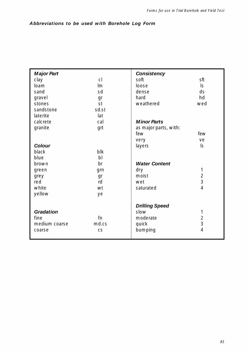
85
Forms for use in Trial Borehole and Yield Test
Abbreviations to be used with Borehole Log Form
Major Partclay clloam lmsand sdgravel grstones stsandstone sd.stlaterite latcalcrete calgranite grt
Colourblack blkblue blbrown brgreen grngrey grred rdwhite wtyellow ye
Gradationfine fnmedium coarse md.cscoarse cs
Consistencysoft sftloose lsdense dshard hdweathered wed
Minor Partsas major parts, with:few fewvery velayers ls
Water Contentdry 1moist 2wet 3saturated 4
Drilling Speedslow 1moderate 2quick 3bumping 4

86
Hand-dug shallow wells
Form for Borehole Yield Test
Village Name Borehole No. (as onBorehole Log Sheet)
Date Bucket volume litres
Water level before test m Test start time (t0)
Pump level for test m Test finish time (t60)
Part 1 - Test Pumping
Time No. of Buckets Water Level (m) Remarks
Part 2 - Recharge Measurement
Time Water Level (m) Remarks
Test done by
Checked by
Date
Date
t0t10t20t30t40t50t60
t61t62t63t64t65t70t75t80t90

87
Drawings for concrete components
Appendix 3.Drawings for Concrete Components

88
Hand-dug shallow wells

89
Drawings for concrete components

90
Hand-dug shallow wells

91
Drawings for concrete components
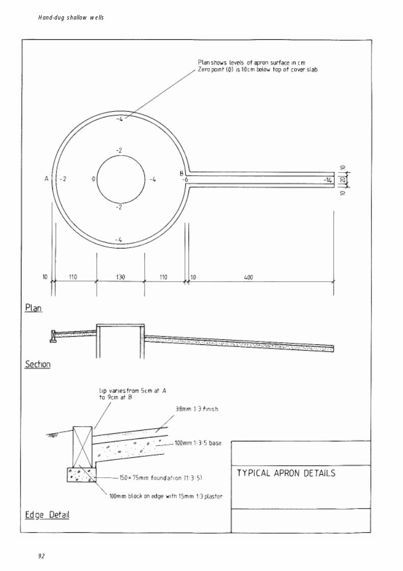
92
Hand-dug shallow wells
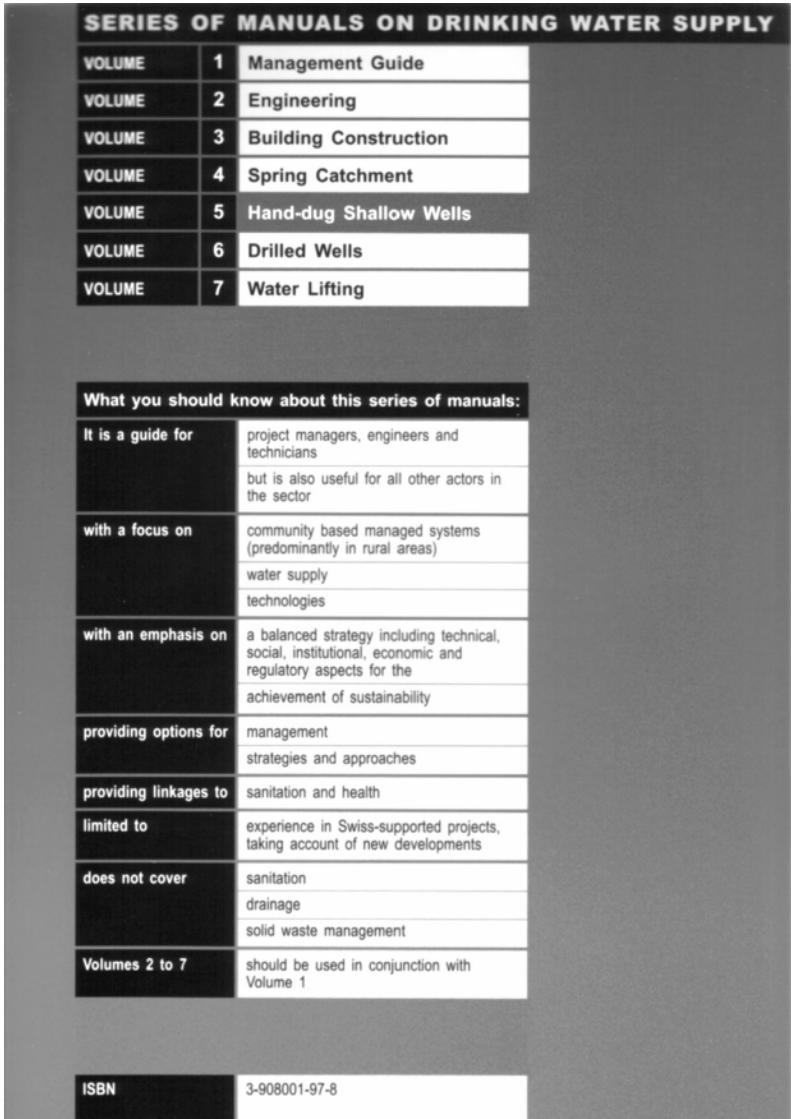


![&RQILJXUDWLRQ :L]DUG](https://static.documents.pub/doc/80x56/61a8afa4f70c766d3378a956/amprqiljxudwlrq-ldug.jpg)


