Abstract— A robot manipulator sharing its workspace withhumans should be able to quickly detect collisions and safelyreact for limiting injuries due to physical contacts. In the absenceof external sensing, relative motions between robot and humanare not predictable and unexpected collisions may occur atany location along the robot arm. Based on physical quantitiessuch as total energy and generalized momentum of the robotmanipulator, we present an efficient collision detection methodthat uses only proprioceptive robot sensors and provides alsodirectional information for a safe robot reaction after collision.The approach is first developed for rigid robot arms and thenextended to the case of robots with elastic joints, proposingdifferent reaction strategies. Experimental results on collisionswith the DLR-III lightweight manipulator are reported.
I. INTRODUCTION
Safety issues are of primary concern when robot manipula-tors are supposed to operate in an unstructured environment,sharing the workspace with a human user and allowing a closephysical cooperation [1], [2]. Accidental collisions that mayharm humans should be avoided by anticipating dangeroussituations, while the effects of actual collisions should bemitigated by having the robot react promptly so as to recovera safe operative condition.
Current research on physical human-robot interaction dealswith different aspects involved in robot dependability: me-chanical design, aimed at reducing manipulator inertia andweight; introduction of compliant components, for reducingthe severity of impacts; additional use of external sensors,so as to allow a fast detection of human-robot proximity;motion planning and control strategies, for minimizing therisks associated to collisions. Each of these aspects is relevantin one or more of the elementary phases in which a physicalhuman-robot interaction can be divided.
In the pre-impact phase, collision avoidance is the primarygoal and requires (at least, local) knowledge of the currentenvironment geometry and computationally intensive motionplanning techniques. Along a similar but simpler line, robotmanufacturers are providing hw/sw facilities for prescribingsafe Cartesian areas that should not be accessed by the robotin any operative condition. Anticipating incipient collisions orrecognizing them in real-time is typically based on the useof additional external sensors, such as sensitive skins [3], on-board vision [4], strain gages, force load cells, and so on.
When a collision occurs, the resulting contact forces duringthe impact phase may be alleviated by pursuing a lightweightrobot design [5], by adding soft visco-elastic covering tothe links [6], or by introducing compliance in the drivingsystem so as to mechanically decouple the heavy motor inertiafrom the link inertia [7]–[9]. Light but stiff link materialscan be combined with harmonic drives, introducing thus jointelasticity, as in the DLR-III robot manipulator. Also, variablestiffness actuation can be used, stiffening the joints duringlow-velocity transients and relaxing them at high-velocityregimes [10], in such a way that tracking performance duringfree motion is not compromised by the introduced compliance.
In the post-impact phase, the first task is to detect thecollision occurrence, which may have happened at any locationalong the robot arm. The controller should then switch to anappropriate reaction strategy, the most simple one being tostop the robot. It is obviously more cost effective to be ableto detect a collision without the need of additional sensors. Arather intuitive scheme is to compare the commanded torque(or, the current in an electrical drive) with the nominal model-based command (i.e., the torque expected in the absenceof collision) and looking for fast transients due to possiblecollision [6], [11], [12]. This approach has been refined byincluding adaptive compliance control [13], [14]. However,tuning of collision detection thresholds in these schemes isdifficult because of the highly varying dynamic characteristicsof the commanded torques. Moreover, their common draw-back (even when robot dynamics is perfectly known) is thatthe inverse dynamics computation for torque comparison isbased on acceleration estimates that introduce noise (due tonumerical differentiation of velocity or position data) and/oran intrinsic delay in a digital implementation.
A detection scheme that works under similar conditionsand avoids the above drawbacks has been recently proposedin [15]. Collisions are viewed as faulty behaviors of therobot actuating system, while the design of a detector takesadvantage of the decoupling property of robot generalizedmomentum [16], [17]. Moreover, this detection scheme isparticularly convenient when it is necessary to switch controlstrategy, being independent from the control method used togenerate the commanded motor torques.
In this paper, we build upon the original idea of [15]
and present a complete treatment of the post-impact phase,from collision detection and identification to robot reactionstrategies. In particular, the directional information on contactforces provided by the identification scheme is used to safelydrive the robot away from the human. Section II recallsthe physical properties of the robot total energy and of itsgeneralized momentum which are relevant for our problem.New detection schemes and an analysis of the detectabilityof collision forces are presented in Section III for rigidmanipulators. The extension to the case of robots with elasticjoints, with alternative sets of reaction strategies, is discussedin Section IV. Finally, Section V reports on the experimentalresults obtained with the DLR-III lightweight manipulator.
II. PRELIMINARIES
We first consider robot manipulators as open kinematicchains of rigid bodies, having N (rotational) rigid joints. Thegeneralized coordinates q ∈ RN can be associated to theposition of the links. The dynamic model is
M(q)q + C(q, q)q + g(q) = τ tot, (1)
where M(q) is the symmetric, positive definite inertia matrix,the Coriolis and centrifugal terms are factorized using thematrix C(q, q) of Christoffel symbols, and g(q) is the gravityvector. In the right-hand side of (1), τ tot contains all activegeneralized torques performing work on q and all dissipativetorques. In the absence of friction and other external torquesacting from the environment, τ tot is just the motor torqueτ . From the skew-symmetry of matrix M(q) − 2C(q, q) itfollows that
M(q) = C(q, q) + CT(q, q). (2)
The total energy of the robot is the sum of its kinetic energyand potential energy due to gravity:
E = T + U =12
qT M(q)q + Ug(q), (3)
with g(q) = (∂Ug(q)/∂q)T . From (1) and (2), it is
E = qT τ tot, (4)
which represents the energy balance in the system.The generalized momentum of the robot is defined as
p = M(q)q. (5)
Using again (1) and (2), its time evolution is given by
p = τ tot + CT(q, q)q − g(q). (6)
The i-th component of p can also be written as
pi = τtot,i −12
qT ∂M(q)∂qi
q − gi(q),
for i = 1, . . . , N . The dynamics of the generalized momentumis thus decoupled component-wise with respect to the torquesacting on the right-hand side of eq. (1).
In the second part of the paper, we will extend ourresults to the case of robots with rigid links but elastic
joints/transmissions. For the dynamic modeling of elastic jointrobots, a doubling of generalized coordinates is needed in aLagrangian formulation. Let θ ∈ RN be the motor positions(as reflected through the gearboxes) and q ∈ RN be thelink positions. Elasticity of the motion transmission elementsis modeled by linear springs introduced at each joint. Weconsider also joint viscosity effects as in [18]. With thestandard assumptions in [19], the dynamic model becomes
M(q)q + C(q, q)q + g(q) = τ tot,J
Bθ + DK−1τ J + τ J = τ ,(7)
whereτ J = K(θ − q) (8)
is the elastic force transmitted through the joints. The motorinertia matrix B and the joint stiffness matrix K are diagonaland positive definite, while D ≥ 0 is the diagonal jointviscosity matrix. In the right-hand side of the first equationin (7), τ tot,J contains the torques performing work on q,i.e., those transmitted through the visco-elastic joints and theexternal torques acting from the environment. When the latterare absent, it is τ tot,J = τ J + DK−1τ J = K(θ − q) +D(θ − q). We note that the analysis presented in this paperapplies, with minor modifications, also to the more completemodel of robots with elastic joints considered, e.g., in [20].
III. DETECTION AND REACTION WITH RIGID ROBOTS
During normal operation, the robot arm may collide witha standing or moving person/obstacle in its workspace. Forsimplicity, we assume that there is at most a single linkinvolved in the collision. Let
V K =[
vK
ωK
]=
[JK,lin(q)JK,ang(q)
]q = JK(q)q ∈ R6
be the linear velocity at the contact point and the angularvelocity of the associated robot link. The quantity V K , andin particular the (geometric) Jacobian JK(q), is unknownin advance. Accordingly, the Cartesian collision forces andmoments are denoted by
F K =[
fK
mK
]∈ R6.
When a collision occurs, the robot dynamics (1) becomes
M(q)q + C(q, q)q + g(q) = τ + τK , (9)
where the joint torque τK associated to the Cartesian collision(generalized) force F K is given by
τK = JTK(q)F K . (10)
A. Collision detection
Define the scalar quantity
σ(t) = kD
[E(t)−
∫ t
0
(qT τ + σ
)ds− E(0)
], (11)
with σ(0) = 0, kD > 0, and where E(t) is the total robotenergy at time t ≥ 0, as defined in (3). Note that σ can be
computed using the measured joint position q and velocity q(possibly obtained through numerical differentiation) and thecommanded motor torque τ . The latter may be the result ofany type of control action. No acceleration measurement isneeded.
Using eqs. (4) and (9), the resulting dynamics of σ is
σ = −kD σ + kD qT τK , (12)
i.e., that of a first-order stable linear filter driven by the workperformed by the joint torques due to collision. During freemotion, σ = 0 up to measurement noise and unmodeleddisturbances. In response to a generic collision, σ raisesexponentially with a time constant 1/kD and detection occursas soon as |σ| > σlow, a suitable threshold whose actual valuedepends on the noise characteristics in the system. Dynamicthresholding can be used for avoiding false detection due tospurious spikes in noisy signals, as shown in [21]. Whencontact is lost, σ rapidly returns to zero. Because of theseproperties, we call σ a collision detection signal.
Not all possible collision situations are detected by thisscheme. With the robot at rest (q = 0), the instantaneousvalue of τK does not affect σ, whereas this will happen onlywhen the robot starts moving. As a consequence, with therobot at rest, true impulsive collision forces/torques cannot bedetected by this scheme, unless they are mechanically filteredby the presence of a soft covering of the arm. On the otherhand, when the robot is in motion, collision can be detectedprovided that the Cartesian collision force produces motion atthe contact. In fact, using eq. (10),
qT τK = qT JTK(q)F K = V T
KF K = 0 ⇐⇒ V K ⊥ F K .
As a simple instance, a lateral (horizontal) force due to ahuman colliding against a 2R planar arm in motion in thevertical plane will not be detected, being fully compensatedby the reaction forces of the manipulator structure. Whenevaluated in terms of reactive motions that the robot may takein response to this collision, such behavior of the detectionscheme is rather natural. In fact, no possible robot motionwould be able to reduce the force loading in this case. Supposenow to add a vertical joint axis at the base (obtaining a 3Relbow-type robot) and let the second and third links be inmotion in the vertical plane as before (i.e., with q1 = 0). Thesame previous lateral force will be felt initially only at the firstjoint (τK,1 6= 0), which is however at rest, so that qT τK = 0and thus σ(0) = 0. Provided that the joint position controlleris soft enough, the first joint will start moving in response tothe collision before the contact force has been removed anddetection may then occur.
B. Collision identification
The previous scheme does not provide any directional infor-mation on the Cartesian collision force, nor is able to identifywhich robot link has collided. To this purpose, following [15],
we define the N -dimensional quantity
r(t)=KI
[p(t)−
∫ t
0
(τ + CT(q, q)q − g(q) + r
)ds− p(0)
](13)
with r(0) = 0, a diagonal gain matrix KI > 0, and wherep(t) is the robot generalized momentum at time t ≥ 0, asdefined in (5). Vector r can be computed using the measured(q, q) and the commanded motor torque τ . In particular, noinversion of the inertia matrix is needed.
From eqs. (6) and (9), the dynamics of r is
r = −KIr + KIτK , (14)
or, component-wise in the Laplace domain,
rj(s)τK,j(s)
=KI,j
s + KI,j, j = 1, . . . , N,
with the N decoupled transfer functions having unitary gains.For (each component of) r, all the appealing properties
of the scalar detection signal σ hold as well. In particular,collision will now be detected when ‖r‖ > rlow or, by workingcomponent-wise, when there exists at least an index j, withj = 1, . . . , N , for which |rj | > rlow,j . In ideal conditions,
KI →∞ ⇒ r ≈ τK ,
which means in practice that the gains should be taken aslarge as possible. Moreover, r is sensitive to collisions evenat q = 0. When the contact occurs on the i-th link of the robotkinematic chain, we have
r =[∗ . . . ∗ ∗ 0 . . . 0
]T.
↑ ↑i + 1 . . . N
(15)
Assuming r ≈ τK = JTK(q)F K , this follows from the fact
that, for a collision on link i, the last N−i columns of the Jaco-bian JK(q) are identically zero. In view of the structure (15),we call r a collision identification signal, or simply a residualbearing this term from the fault detection literature. The first icomponents of vector r will be generically different from zero,at least for the time interval of contact, and will start decayingexponentially toward zero as soon as contact is lost. Theresidual r will be affected only by Cartesian collision forcesF K that perform virtual work on admissible robot motion,i.e., those forces that do not belong to the kernel of JT
K(q).More in general, the sensitivity to F K of each of the affectedresiduals (proximal to the robot base) will vary with the armconfiguration (see also [15]). Thanks to the properties of thegeneralized momentum, this dynamic analysis can be carriedout based only on the static transformation matrix JT
K(q) fromCartesian forces to joint torques. In fact, the residual dynamicsin eq. (14) is unaffected by robot velocity and acceleration.
C. Reaction strategy
In general, we suppose that the robot is always gravitycompensated, i.e.,
τ = τ ′ + g(q), (16)
with τ ′ given by any motion control law. Enforcing sucha zero-gravity condition is useful for guaranteeing a safebehavior [1], as robot motion will not be biased along thegravity direction. When motor torques are provided by acontrol law of the form (16), the computation of the detectionsignal σ and of the residual r may be simplified. In (11), τ canbe replaced by τ ′ and the total energy E by the kinetic energyT , while in (13) one could just use τ ′ in place of τ − g(q).These modifications will not alter the resulting dynamics (12)(linear for σ) and (14) (linear and decoupled for r).
During normal operation (pre-impact phase), it is convenientto apply a control law that provides accurate trajectory trackingin free motion while displaying passive properties (spring-damper type) in response to unexpected collisions. A typicalchoice is a joint PD linear feedback law
τ ′ = τ ′d + KP (qd − q)−KDq, (17)
with (diagonal) KP > 0 and KD > 0, and with the nominalfeedforward term computed on the desired trajectory qd(t) as
τ ′d = M(qd)qd + C(qd, qd)qd + KDqd.
The simplest reaction strategy to a collision would be tostop the robot by using its brakes [6]. However, this would notremove the arm from direct contact with a human, generatingan unpleasant feeling of permanent danger or even squeezingthe person in a narrow environment. Instead, the directionalinformation embedded in the residual vector r can be usedin the post-impact phase, by switching control to a morefriendly behavior. In response to a collision, the residual rrapidly increases and reaches peak values that depend on theseverity of the impact. As soon as the detection threshold(s)is exceeded, the control law (17) is switched to the followingsimple reflex strategy:
τ ′ = KRr, (diagonal) KR > 0. (18)
The idea is to use the motor torques so as to (over)react tothe external collision force along the same resulting direction,as seen at the level of joint torques. By combining eqs. (9),(16), and (18), and assuming the limit case of r = τK , aftercollision detection the robot dynamics becomes
(I + KR)−1 (M(q)q + C(q, q)q) = τK . (19)
The robot inertial terms, as seen by a collision torque, arescaled by a factor larger than unity —a lighter pushable robotis obtained. In practice, because of the filtering introducedby eq. (14), this result will be obtained only partially. Equa-tion (18) is clearly an active control scheme, as additionalenergy is feed into the system after the collision has beendetected. The expected outcome, however, is that the robotbounces back in a direction (implicitly defined by eq. (18)and the robot arm dynamics) which is the most advantageousfor escaping contacts, at least locally. When the contact is lost,and in the absence of further collisions, the residual will returnto zero.
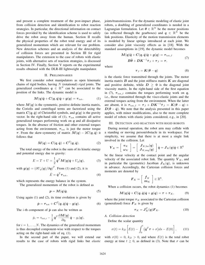
Fig. 1. Robot operation states
D. Energy dissipation
In the presence of very low friction, it may be necessary tolimit the excursion of the robot reflex motion. In such cases,the control law (18) is only kept until ‖r‖ ≤ rstop, when aphase of maximum dissipation of kinetic energy is executedin order to rapidly stop the robot in a safe configuration. Letthe available motor torques at each joint be bounded by
|τi| ≤ τmax,i, i = 1, . . . , N.
Part of this motor torque is spent for the gravity compensationin eq. (16). By defining the configuration-dependent bounds
τ ′m,i(q) = −(τmax,i + gi(q)) < 0
τ ′M,i(q) = τmax,i − gi(q) > 0,
the remaining part of the available torques should satisfy
τ ′m,i(q) ≤ τ ′i ≤ τ ′M,i(q), i = 1, . . . , N.
Since the time evolution of the kinetic energy is T = qT τ ′,the following control law locally realizes the largest decreaseof T :
τi =
τ ′m,i(q) if qi ≥ εi
τ ′m,i(q)qi/εi if εi > qi ≥ 0τ ′M,i(q)qi/εi if − εi < qi ≤ 0
τ ′M,i(q) if qi ≤ −εi
+ gi(q),
with i = 1, . . . , N . For each velocity qi, the insertion of asmall ultimate region of amplitude 2εi > 0 allows a trade-off between the almost minimum-time solution and a smoothreaching of the final condition q = 0.
The robot operation states and their transition conditions areshown in Fig 1. Note that as long as the collision flag is up,any further collision will keep the robot in the reflex reactivestate. In other terms, the generator of the collision residual rin eq. (13) is permanently active.
IV. EXTENSION TO ROBOTS WITH JOINT ELASTICITY
For a serial robot manipulator with significantjoint/transmission elasticity, when a collision occurs thedynamic model (7) becomes
M(q)q + C(q, q)q + g(q) = τ J + DK−1τ J + τK (20)
Bθ + DK−1τ J + τ J = τ , (21)
with τK = JTK(q)F K as before.
The extension of the collision detection and identificationschemes developed in Sect. III for the rigid case can bemade in different ways. One possibility is to work with thecomplete energy of the robot, by including the kinetic energyof the motors and the potential energy associated to the jointelasticity in the definition of a detection signal σEJ, or byconsidering also the generalized momentum associated to themotors in the definition of a residual rEJ. Such schemes wouldin principle require the measure of the whole state (θ, θ, q, q)of the robot, together with the knowledge of the commandedtorque τ .
However, in view of the application of our methods tothe DLR-III lightweight manipulator, we take advantage ofthe specific sensing devices available on board of this robot.In particular, every joint is equipped with a high-resolutionincremental position sensor on the motor side and an integratedjoint torque sensor, so that θ and τ J are directly available.From eq. (8), the link position is computed as q = θ−K−1τ J .Finally, q and τ J are obtained by numerical differentiation.
As a result, it is possible to consider only eq. (20) andhandle the measured joint torque τ J as the equivalent ofthe commanded torque τ in the rigid robot model (9).More specifically, substituting τ with τ J + DK−1τ J inthe expressions (11) and (13), we obtain similar collisiondetection schemes and identification properties. In particular,the residual rEJ ∈ RN for the visco-elastic joint case isdefined as
rEJ(t) = KI
[p(t)−
∫ t
0
(τ J + DK−1τ J
+ CT(q, q)q − g(q) + rEJ
)ds− p(0)
],
(22)
with rEJ(0) = 0 and a (diagonal) gain matrix KI > 0. Thisleads again to the linear and decoupled residual dynamics
rEJ = −KIrEJ + KIτK .
A. DLR-III controller
We recall first the form of the robot control law usedfor general tasks with the DLR-III arm, in which reactionstrategies to collisions have been inserted as additional controlmodalities. An interesting feature of this general controller,used already for Cartesian compliance control [18], is thepossibility of shaping the motor inertia by a joint torquefeedback of the form
τ = BB−1θ u + (I −BB−1
θ )τ J
+(D −BB−1θ Ds)K−1τ J ,
(23)
where u ∈ RN is the new torque command, Bθ is thedesired (still diagonal) motor inertia, with 0 < Bθ < B,and Ds > 0 is the desired joint torque damping (diagonal)matrix. Substituting eq. (23) in (21) yields
Bθθ + DsK−1τ J + τ J = u.
As a result, the inertia of the robot motors appears to bereduced —a convenient property for physical human-robotinteraction. In fact, the motor inertia B is a significant partof the total inertia of the DLR-III manipulator: by reducing itto Bθ, the impact energy of the robot at a given velocity isscaled accordingly. Moreover, the effect of friction will be alsoreduced, allowing the human to move the robot by applyingvery low external forces.
A passivity-based controller, similar to eq. (17) of the rigidcase, is obtained by choosing
u = τ J,d + Kθ(θd − θ)−Dθθ, (24)
with positive definite, diagonal matrices Kθ and Dθ. Thefeedforward joint torque τ J,d and the motor reference θd
can be directly computed from the desired link trajectoryqd(t) (see, e.g., [22]). We note that the passivity propertiesare preserved provided that the following condition on theintroduced (diagonal) damping matrices is satisfied [18]:
D ≥ 14(Ds −D)T Dθ (Ds −D).
Combining eqs. (23) and (24) yields the overall controller
where the expressions of the final gain matrices can be easilyobtained from the previous definitions. Equation (25) repre-sents a full-state feedback with respect to suitable, possiblytime-varying, reference values. Having an explicit joint torquefeedback in addition to a position feedback loop, the abovecontrol law can be parametrized by a suitable choice of itsgains so as to yield a position, a torque, or an impedancecontroller [23]. This fact will be used for implementingdifferent strategies of robot reaction to collisions in a singleframework.
Realizing a zero-gravity condition for an elastic joint robot,with a choice equivalent to eq. (16) of the rigid case, isnot as immediate. Adding just g(q) in the expression of τis not enough to completely eliminate gravity effects fromthe picture. Rather, it can be shown that the more complexdynamic term g(q)+BK−1g(q) would be needed. However,it is often sufficient to compensate gravity in any static con-figuration. This can be more easily achieved by adopting theiterative scheme of [24] where, for each motor measurementθ, a gravity term g(θ) is computed such that
This approach fits well within the passivity framework ofthe controller. Another feasible scheme for on-line (partial)compensation of gravity has been proposed in [9].
B. Reaction strategies
The residual rEJ in eq. (22) is used for detecting a collisionand identifying a safe direction for the reactive motion of therobot. In the presence of joint elasticity, however, a number ofalternative strategies can be realized. As baseline behaviors inthe performed collision experiments, we have taken the caseof no reaction at all (Strategy 0) and of immediate stop ofthe trajectory generation with simultaneous high-gain positioncontrol (Strategy 1). With reference to the general controllaw (25), three reactive strategies have been considered.
• Zero-gravity torque reaction (Strategy 2)
τ J,d = g(θ), KP = 0.
This strategy leaves the robot floating in space in responseto the collision force, while motion is damped at themotor side.
• Reflex torque reaction (Strategy 3)
τ J,d = KRrEJ + g(θ), KP = 0.
This strategy is the closest to eq. (18) of the rigid case.Similar considerations can be made on the reduction ofthe apparent total inertia. In the limit case of KR = 0,this strategy collapses in the previous one.
• Admittance control reaction (Strategy 4)
τ J,d = g(θ), θd = KRrEJ.
In this case, the defined motor reference velocity θd isintegrated so as to provide θd.
V. EXPERIMENTS WITH THE DLR-III MANIPULATOR
We have performed several tests on collision detectionwith the DLR-III lightweight manipulator and using the robotreaction strategies defined in Section IV-B.
Size and power of the DLR-III manipulator are fairly similarto that of a human arm, with an outreach of about 1 m.The robot has 7 rotary joints, with spherical shoulder andwrist axes and a modular link/joint structure, a total weightof about 13.5 kg, including brushless DC motors, electronics,and power converters (all integrated in the arm), and HarmonicDrives gear units with reduction ratios of 160 (100 for joint5) and stiffnesses Ki in the range 10÷ 15 · 103 Nm/rad. Themaximum output torques delivered by the motors range from180 Nm (first two joints) to 80 Nm (joints 3 and 4), downto 30 Nm (last three joints). The maximum joint velocitiesexceed 100/s, corresponding to a maximum attainable linearvelocity at the end-effector larger than 4 m/s. The robot isequipped with electromagnetic emergency brakes. The high-level control loop is implemented at 1 ms rate, with local jointcontrol acting every 333 µs.
A preliminary evaluation of the HIC index [7] has beencarried out using a dummy head instrumented with a three-dimensional accelerometer [25]. We report here numericalresults obtained on repeated collisions with a balloon (seeFigs. 2–6) and qualitative results for collisions with humans(see Fig. 7).
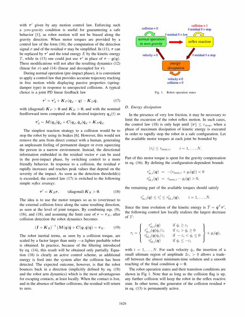
Fig. 2. Collision with a balloon (motion at 100/s) and robot reaction
The balloon experiment was chosen for its repeatableconditions needed to compare different reaction strategies.Tests were performed using a trapezoidal velocity profile,with cruise speed between 10/s (slow speed impact) and100/s (fast speed impact), as reference trajectory θd(t) forthe motors. The stretched upward arm posture corresponds toθ = q = 0 (gravity is zero in this configuration). Motion wasplanned between an initial and a final position specified byθin =
[60 31 −78 23 158 −15 −15
]T(deg) and
θfin =[
60 65 −78 53 158 −15 −15]T
, respec-tively (motion is thus limited to joints 2 and 4). The robot hitsthe clamped balloon with its spherical wrist while coming fromabove (Fig. 2).
The detection gains were chosen as KI = 25 · I , whilethe reflex reaction gains were selected as KR = 1.4 · I (forStrategy 3) or KR = 0.05·I (for Strategy 4). The component-wise detection thresholds rlow,j , j = 1, . . . , 7, have been setat 10% of the maximum output torques available at each joint.This guarantees a reliable detection without false alarms andwith just a one-step delay (1 ms). However, current controlcommunication timings in the system set-up introduce anadditional delay in the order of 4− 6 ms.
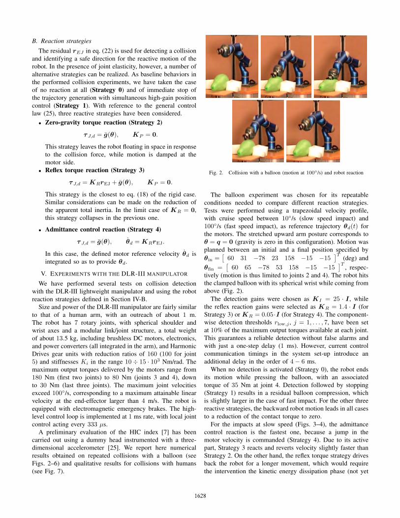
When no detection is activated (Strategy 0), the robot endsits motion while pressing the balloon, with an associatedtorque of 35 Nm at joint 4. Detection followed by stopping(Strategy 1) results in a residual balloon compression, whichis slightly larger in the case of fast impact. For the other threereactive strategies, the backward robot motion leads in all casesto a reduction of the contact torque to zero.
For the impacts at slow speed (Figs. 3–4), the admittancecontrol reaction is the fastest one, because a jump in themotor velocity is commanded (Strategy 4). Due to its activepart, Strategy 3 reacts and reverts velocity slightly faster thanStrategy 2. On the other hand, the reflex torque strategy drivesback the robot for a longer movement, which would requirethe intervention the kinetic energy dissipation phase (not yet
Fig. 4. Velocity q4 at joint 4 with different reaction strategies (impact atslow speed = 10/s)
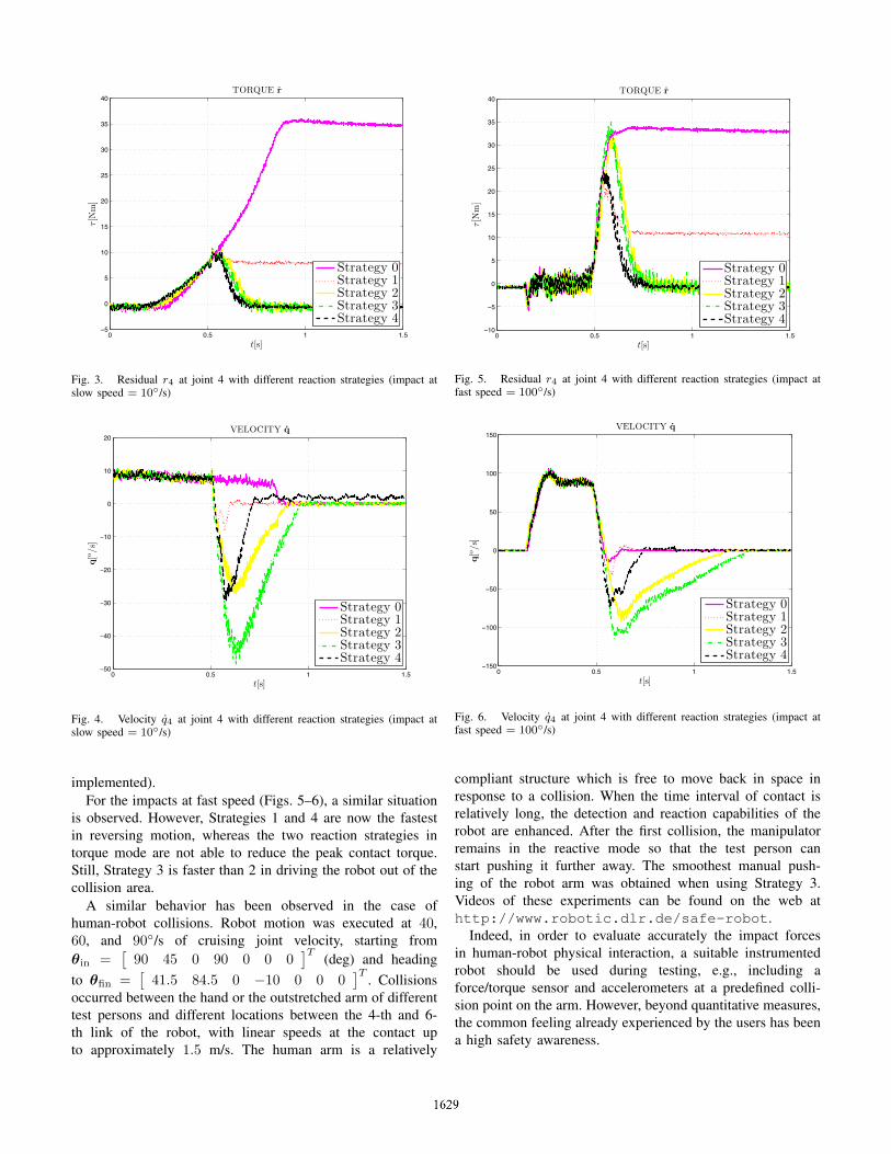
implemented).For the impacts at fast speed (Figs. 5–6), a similar situation
is observed. However, Strategies 1 and 4 are now the fastestin reversing motion, whereas the two reaction strategies intorque mode are not able to reduce the peak contact torque.Still, Strategy 3 is faster than 2 in driving the robot out of thecollision area.
A similar behavior has been observed in the case ofhuman-robot collisions. Robot motion was executed at 40,60, and 90/s of cruising joint velocity, starting fromθin =
[90 45 0 90 0 0 0
]T(deg) and heading
to θfin =[
41.5 84.5 0 −10 0 0 0]T
. Collisionsoccurred between the hand or the outstretched arm of differenttest persons and different locations between the 4-th and 6-th link of the robot, with linear speeds at the contact upto approximately 1.5 m/s. The human arm is a relatively
Fig. 6. Velocity q4 at joint 4 with different reaction strategies (impact atfast speed = 100/s)
compliant structure which is free to move back in space inresponse to a collision. When the time interval of contact isrelatively long, the detection and reaction capabilities of therobot are enhanced. After the first collision, the manipulatorremains in the reactive mode so that the test person canstart pushing it further away. The smoothest manual push-ing of the robot arm was obtained when using Strategy 3.Videos of these experiments can be found on the web athttp://www.robotic.dlr.de/safe-robot.
Indeed, in order to evaluate accurately the impact forcesin human-robot physical interaction, a suitable instrumentedrobot should be used during testing, e.g., including aforce/torque sensor and accelerometers at a predefined colli-sion point on the arm. However, beyond quantitative measures,the common feeling already experienced by the users has beena high safety awareness.
Fig. 7. Human-robot collision detection and reaction
VI. CONCLUSIONS
We have presented a complete approach, from detectionto reaction, for handling human-robot collisions without theneed of external sensing. Collision detection and identificationsignals can be efficiently generated resorting to energy argu-ments or based on the robot generalized momentum and byusing only proprioceptive measurements. After collision hasbeen detected, a reactive control strategy enables to reducethe effective inertia seen by the Cartesian contact forces. Therobot retracts itself safely and rapidly away from the collisionarea, using the local directional information collected duringthe impact. The developed methodology covers both the caseof rigid manipulators and of robots with elastic joints.
On-going work is concerned with acceleration-driven col-lision detection and the reduction of control communicationdelays in our robotic set-up, as well as with a more accurateevaluation of several severity indices of the impacts and ofthe beneficial inclusion of compliant coverages. Furthermore,robot redundancy will be exploited in order to devise reactionstrategies that try to complete a given Cartesian motion task,despite of the detected collision.
ACKNOWLEDGMENTS
This work was performed while the first author was visitingDLR, with the support of a Research Award for foreignresearchers granted by the Helmholtz-Humboldt Association.
REFERENCES
[1] J. Heinzmann and A. Zelinsky, “Quantitative safety guarantees forphysical human-robot interaction,” Int. J. of Robotics Research, vol. 22,no. 7/8, pp. 479–504, 2003.
[2] K. Ikuta, H. Ishii, and M. Nokata, “Safety evaluation method of designand control for human-care robots,” Int. J. of Robotics Research, vol. 22,no. 7/8, pp. 281–297, 2003.
[3] V. Lumelsky and E. Cheung, “Real-time collision avoidance in teleop-erated whole-sensitive robot arm manipulator,” IEEE Trans. on Systems,Man, and Cybernetics, vol. 23, no. 1, pp. 194–203, 1993.
[4] D. M. Ebert and D. D. Henrich, “Safe human-robot-cooperation: Image-based collision detection for industrial robots,” in Proc. IEEE/RSJ Int.Conf. on Intelligent Robots and Systems, pp. 1826–1831, 2002.
[5] G. Hirzinger, A. Albu-Schaffer, M. Hahnle, I. Schaefer, and N. Sporer,“On a new generation of torque controlled light-weight robots,” in Proc.IEEE Int. Conf. on Robotics and Automation, pp. 3356–3363, 2001.
[6] Y. Yamada, Y. Hirasawa, S. Huang, Y. Uematsu, and K. Suita, “Human-robot contact in the safeguarding space,” IEEE/ASME Trans. on Mecha-tronics, vol. 2, no. 4, pp. 230–236, 1997.
[7] A. Bicchi and G. Tonietti, “Fast and soft arm tactics: Dealing with thesafety-performance tradeoff in robot arms design and control,” IEEERobotics and Automation Mag., vol. 11, no. 2, pp. 22–33, 2004.
[8] M. Zinn, O. Khatib, B. Roth, and J. K. Salisbury, “A new actuationapproach for human-friendly robot design,” Int. J. of Robotics Research,vol. 23, no. 4/5, pp. 379–398, 2005.
[9] A. De Luca, B. Siciliano, and L. Zollo, “PD control with on-line gravitycompensation for robots with elastic joints: Theory and experiments,”Automatica, vol. 41, no. 10, pp. 1809–1819, 2005.
[10] G. Tonietti, R. Schiavi, and A. Bicchi, “Design and control of a variablestiffness actuator for safe and fast physical human/robot interaction,” inProc. IEEE Int. Conf. on Robotics and Automation, pp. 528–533, 2005.
[11] S. Takakura, T. Murakami, and K. Ohnishi, “An approach to collisiondetection and recovery motion in industrial robot,” in Proc. 15th AnnualConf. of IEEE Industrial Electronics Society (IECON89), (Boston, MA),pp. 421–426, 1989.
[12] K. Suita, Y. Yamada, N. Tsuchida, K. Imai, H. Ikeda, and N. Sugimoto,“A failure-to-safety ‘kyozon’ system with simple contact detection andstop capabilities for safe human-autonomous robot coexistence,” in Proc.IEEE Int. Conf. on Robotics and Automation, pp. 3089–3096, 1995.
[13] K. Kosuge and T. Matsumoto, “Collision detection of manipulator basedon adaptive control law,” in Proc. IEEE/ASME Int. Conf. on AdvancedIntelligent Mechatronics, pp. 117–122, 2001.
[14] S. Morinaga and K. Kosuge, “Collision detection system for manipulatorbased on adaptive impedance control law,” in Proc. IEEE Int. Conf. onRobotics and Automation, pp. 1080–1085, 2003.
[15] A. De Luca and R. Mattone, “Sensorless robot collision detection andhybrid force/motion control,” in Proc. IEEE Int. Conf. on Robotics andAutomation, pp. 1011–1016, 2005.
[16] A. De Luca and R. Mattone, “Actuator fault detection and isolationusing generalized momenta,” in Proc. IEEE Int. Conf. on Robotics andAutomation, pp. 634–639, 2003.
[17] H.-B. Kuntze, C. W. Frey, K. Giesen, and G. Milighetti, “Fault tolerantsupervisory control of human interactive robots,” in Proc. IFAC Work. onAdvanced Control and Diagnosis (ACD03), (Duisburg, D), pp. 55–60,2003.
[18] A. Albu-Schaffer, C. Ott, and G. Hirzinger, “A passivity based cartesianimpedance controller for flexible joint robots – Part II: Full statefeedback, impedance design and experiment,” in Proc. IEEE Int. Conf.on Robotics and Automation, pp. 2666–2672, 2004.
[19] M. W. Spong, “Modeling and control of elastic joint robots,” ASMEJ. of Dynamic Systems, Measurements, and Control, vol. 109, no. 4,pp. 310–319, 1987.
[20] A. De Luca and P. Lucibello, “A general algorithm for dynamic feedbacklinearization of robots with elastic joints,” in Proc. IEEE Int. Conf. onRobotics and Automation, pp. 504–510, 1998.
[21] A. De Luca and R. Mattone, “An adapt-and-detect actuator FDI schemefor robot manipulators,” in Proc. IEEE Int. Conf. on Robotics andAutomation, pp. 4975–4980, 2004.
[22] A. De Luca, “Feedforward/feedback laws for the control of flexiblerobots,” in Proc. IEEE Int. Conf. on Robotics and Automation, pp. 233–240, 2000.
[23] A. Albu-Schaffer and G. Hirzinger, “A globally stable state-feedbackcontroller for flexible joint robots,” Advanced Robotics, vol. 15, no. 8,pp. 799–814, 2001.
[24] C. Ott, A. Albu-Schaffer, A. Kugi, S. Stramigioli, and G. Hirzinger, “Apassivity based cartesian impedance controller for flexible joint robots -Part I: Torque feedback and gravity compensation,” in Proc. IEEE Int.Conf. on Robotics and Automation, pp. 2659–2665, 2004.
[25] S. Haddadin, “Bewertungskriterien und Regelungsstrukturen fur einesichere Mensch-Roboter Interaktion,” diplomarbeit, DLR, Oberpfaffen-hofen, D, January 2006.