Colloidal PbS and PbSeS Quantum Dot Sensitized Solar CellsPrepared by Electrophoretic DepositionNima Parsi Benehkohal,*,† Victoria Gonzalez-Pedro,‡ Pablo P. Boix,‡ Sudam Chavhan,§
Ramon Tena-Zaera,§ George P. Demopoulos,† and Ivan Mora-Sero*,‡
†Department of Materials Engineering, McGill University, Montreal, Quebec H3A 2B2, Canada‡Photovoltaic and Optoelectronic Devices Group, Departament de Física, Universitat Jaume I, 12071 Castello de la Plana, Spain§Energy Department, IK4-CIDETEC, Parque Tecnologico, Paseo Miramon 196, 20009 Donostia-San Sebastian, Spain
*S Supporting Information
ABSTRACT: Here we report the development of quantum dot sensitized solarcells (QDSCs) using colloidal PbS and PbSeS quantum dots (QDs) andpolysulfide electrolyte for high photocurrents. QDSCs have been prepared in anovel sensitizing way employing electrophoretic deposition (EPD) andprotecting the colloidal QDs from corrosive electrolyte with a CdS coating.EPD allows a rapid, uniform, and effective sensitization with QDs, while the CdScoating stabilizes the electrode. The effect of electrophoretic deposition time andof colloidal QD size on cell efficiency is analyzed. Efficiencies as high as 2.1 ± 0.2% are reported.
■ INTRODUCTION
The development of third-generation solar cells overcoming theShockley−Queisser efficiency limit for a single absorber, 31%,1
is one of the most fascinating challenges in the energy researchfield. In this aspect, semiconductor quantum dots (QDs) haveshown extremely attractive properties for the development ofsolar cells overcoming the current limitations.2 The demon-stration of an efficient multiple exciton generation (MEG)process in colloidal QDs,3,4 despite certain controversy,5 hasaroused a huge interest in the use of these materials inphotovoltaic devices. This interest has been reinforced with therecent reports of absorbed photon-to-current efficiency(APCE) close to 200%6 and incident photon-to-currentefficiency (IPCE) as high as 114%.7 These achievements areacquired by using QDs with IR absorption, PbS6 and PbSe.7 Inthe former case PbS QDs have been employed in a sensitizedsolar cell configuration.8 Electron−hole pairs, photogeneratedand produced by impact ionization in an MEG process, in PbScolloidal QDs are quickly separated into two different media.Electrons are injected into flat TiO2 single crystals, while holesare regenerated by a polysulfide electrolyte.6 NanostructuredTiO2 electrodes, instead of flat electrodes, enhance dramaticallylight harvesting, but two main problems have to be solved: (i)uniform sensitization with colloidal QDs of a nanostructuredelectrode along all its thickness and (ii) development of a stableQDSC configuration with colloidal PbS QDs as sensitizers. Wehave addressed these problems preparing colloidal PbS andPbSeS quantum dot sensitized solar cells (QDSCs) in a novelsensitizing way employing electrophoretic deposition (EPD)and protecting the colloidal QDs from corrosive electrolyteswith a CdS coating. We have analyzed the effect ofelectrophoretic deposition time and QD size in the final solarcell performance, obtaining efficiencies as high as 2.1 ± 0.2%.
These results represent a significant advance in the develop-ment of colloidal QDSCs with light absorption in the IR region.In addition, we discuss the role of QDs in the recombinationprocess of the analyzed solar cells.Electrophoretic deposition has been used for the deposition
of TiO2 nanoparticles in solar cell9 or photocatalytic10
applications. In addition, it is a method also employed todeposit colloidal QDs, especially CdSe, on different materialssuch as Au,11,12 patterned electrodes,13 stacked-cup carbonnanotubes,14 and polymer templates.15 Colloidal CdSe QDshave also been deposited by electrophoresis for photovoltaicpurposes. Electrophoretic deposition of CdSe-C60 was used forthe preparation of composite films for solar energy gen-eration.16 Flexible QDSCs have been fabricated by using theelectrophoretic deposition of CdSe QDs on ZnO nanorods,obtaining efficiencies of 0.98%.17 Higher efficiencies, 1.7%, havebeen reported for TiO2 nanostructured electrodes with a ZnScoating of the colloidal CdSe QDs,18 but there is no report onthe use of EPD of PbS or PbSeS QDs. Electrophoreticdeposition presents a significant advantage over otherdeposition techniques for colloidal QDs, either as linker-assisted19−21 or directly adsorbed,19,21 because of its simplicityand short deposition time. While for electrophoretic depositiontimes as short as 2 h were sufficient for effective coating,18
several hours or even days are needed with othertechniques.19−21
The use of PbS QDs in QDSCs has been significantly lessthan the utilization of CdSe QDs, in spite of the higher lightharvesting potential of PbS QDs due to their tunable
Received: June 7, 2012Revised: July 12, 2012Published: July 13, 2012
absorption in the IR range. This is largely due to the difficultyof finding an appropriate electrolyte for PbS in which it isstable. PbS is not stable with iodine nor polysulfide redoxelectrolytes.22−24 Thus, most of the reports on PbS QDSCs arefor all-solid devices.23,25−27 In the case of using a liquidelectrolyte for hole transport in PbS QDSCs, the highestreported efficiency, 0.62%, has been reported using a Co redoxelectrolyte,28 at 1 sun, and with PbS grown by the successiveionic layer absorption and reaction (SILAR) method. We haveshown that, by employing the same deposition technique,stable QDSCs using polysulfide electrolyte can be obtained bycoating the PbS QDs with CdS,29 reporting a significantefficiency of 2.36% using nanostructured TiO2 electrodes.30
Similar efficiencies have been obtained using SnO2 electrodes,31
and outstanding efficiencies of 3.82% have been obtained usingTiO2 photoanodes with hierarchical pore distribution,32
employing again in both cases the SILAR growth. However,the presynthesis of colloidal QDs allows the preparation ofQDs with better defined properties than QD samples preparedby SILAR. Treatment of colloidal PbS/TiO2 cells using CdSgrown by the SILAR method has been successfully appliedbefore in a depleted heterojunction solar cell configuration.33
The ultrafast electron injection from PbS colloidal QDs intoTiO2 as fast as 6.4 fs34 points to the capability of extraction ofcharge generated by MEG. Thus, the preparation of cells withcolloidal QDs is extremely interesting.
■ EXPERIMENTAL SECTIONColloidal QDs. PbSSe QDs with oleic acid capping were
kindly provided by NANOCO, while PbS QDs were purchasedfrom Evident Technologies. Both QDs were solved in toluene.
TiO2 Photoanode Preparation. After the fluorine-dopedtin oxide (FTO) glasses (Pilkington TEC 8 with 8 Ω2 sheetresistance) were cleaned, a compact layer of TiO2 wasdeposited on them by spray pyrolysis of titanium(IV)bis(acetoacetonato) bis(isopropanoxylate) followed by sinter-ing at 450 °C to improve the electrical contact between thenanoparticles. TiO2 photoanodes were prepared by “double-layer” screen-printing on FTO glass using two different TiO2pastes, including a light-scattering layer on top of thetransparent TiO2 film. The transparent layer is formed by 20nm TiO2 nanoparticles (18NR-AO, Dyesol), and the opaquelayer contains 300−400 nm TiO2 particles (WER4-O Dyesol).
Finally, the resulting film was sintered again at 450 °C for 30min. The total thickness of the photoanodes was 15 ± 1 μm,measured with a Dektack 6 profilometer from Veeco.
Electrophoretic Deposition of the QDs on the TiO2Electrodes. QDs were diluted in toluene, with concentrationsof ∼2.2 × 10⁻⁶ M. Two TiO2 FTO electrodes were immersedvertically in the QD solution parallel to each other. Thedeposition area of the electrodes was about 0.25 cm2, and thedistance between them was adjusted at 1 cm. A voltage of 200V was applied for 5−90 min. QDs were deposited on both thecathode and anode electrodes similar to previous reports.18
Fresh layers at each deposition time were taken from theelectrophoretic cell, rinsed several times with toluene to washoff unbound QDs, subsequently rinsed with ethanol, and driedat room temperature. After electrophoretic deposition colloidalQDs were coated with a CdS layer grown by SILAR. TheSILAR process was carried out following the method recentlydescribed. Cd2+ ions were deposited from an ethanolic 0.05 Msolution of Cd(NO3)2·4H2O. The sulfide source was a 0.05 Msolution of Na2S·9 H2O in methanol/water (50/50, v/v). Asingle SILAR cycle consisted of 1 min of dip-coating of theTiO2 working electrode into the metal precursors andsubsequent rinsing for 1 min in ethanol. Subsequently, thesample was dipped into the sulfide solution for 1 min andrinsed in methanol/water (50/50, v/v) for an additional 1 min.This procedure constitutes a complete SILAR cycle. TheSILAR process was carried out automatically using a robotdesigned by ISTest. All the analyzed cells in this work werecoated with ZnS, by being alternately dipped into 0.1 MZn(CH3COO)2 and 0.1 M Na2S Milli-Q water solutions for 1min/dip and subsequently rinsed with Milli-Q ultrapure water.Two SILAR cycles were employed for ZnS coating.
QDSC Preparation. Porous Cu2S was used as a counterelectrode, which was prepared by immersing brass in HClsolution at 70 °C for 5 min and subsequently dipping it intopolysulfide solution for 10 min.19 The counter electrode and aQD-sensitized electrode were assembled into a sandwich-typeconfiguration using a Scotch spacer (thickness 50 μm) and witha droplet (10 μL) of polysulfide electrolyte. The polysulfideelectrolyte was composed of 1 M Na2S, 1 M S, and 0.1 MNaOH solution in Milli-Q ultrapure water.
Photoanode and Solar Cell Characterization. The crosssection morphology of the TiO2−PbSeS electrode films wasinvestigated using a field emission scanning electron micro-scope (ULTRA plus ZEISS FESEM). Energy-dispersive X-rayspectroscopy (Apollo X, Ametek EDAX) was employed to mapand determine the distribution of chemical elements. A BrukerAXS-D8 Advance X-ray diffractometer, using Cu Kα radiation,was used to analyze the structural properties of anodes beforeand after light sensitization. The optical absorption spectra ofthe photoanodes were recorded at 300−700 nm using a Cary500 UV−vis Varian photospectroscometer. The IPCE measure-ments were done using a 150 W Xe lamp coupled with amonochromator controlled by a computer; the photocurrentwas measured using a 70310 optical power meter from OrielInstruments, using a Si photodiode to calibrate the system.QDSCs were characterized by current−voltage and impedancespectroscopy using a 0.1256 cm2 mask and no antireflectivelayer. These measurements were performed employing the PG-STAT30 potentiostat (Autolab) and solar simulator at AM1.5G, where the light intensity was adjusted with an NRELcalibrated Si solar cell with a KG-5 filter to 1 sun intensity (100mW/cm2). For most of the conditions analyzed in this work
Table 1. Solar Cell Parameters of QDSCs PreparedEmploying PbSeS 800 nm QDs and DifferentElectrophoresis Deposition Times:a Open Circuit Voltage,Voc, Short Circuit Current, Jsc, Fill Factor, FF, andPhotovoltaic Conversion Efficiency, η
a5CdS is a sample prepared with no PbSeS QDs and just five SILARcycles of CdS and two SILAR cycles of ZnS. The rest of the samplesare identified by the PbSeS electrophoresis deposition time; inaddition, all these samples have also been coated with five SILARcycles of CdS and two SILAR cycles of ZnS.
The Journal of Physical Chemistry C Article
dx.doi.org/10.1021/jp3056009 | J. Phys. Chem. C 2012, 116, 16391−1639716392
more than one cell was prepared; standard errors werecalculated for these conditions and are included in Tables 1and 2. In a few cases just a single cell was analyzed; in thosecases errors are not provided. IS measurements were carriedout in the dark at different bias voltages with 10 mV ACperturbation over a frequency range of 400 kHz to 10 mHz.
■ RESULTS AND DISCUSSION
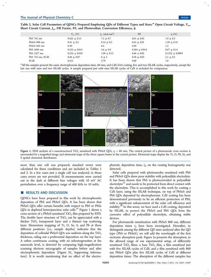
QDSCs have been prepared in this work by electrophoreticdeposition of PbS and PbSeS QDs. It has been shown thatPbSeS QDs offer certain benefits with respect to PbS or PbSeQDs in depleted heterojunction solar cells.35 Figure 1 shows across section of a PbSeS-sensitized TiO2 film prepared by EPD.The double layer structure of TiO2 can be appreciated with athicker TiO2 transparent layer and a thinner top scatteringlayer. Elementary mapping of Ti, O, Se, S, and Pb at threedifferent positions (i.e., sample depths) indicates that thedeposition of colloidal PbSeS QDs was uniform along the TiO2
thickness, ruling out a preferential deposition on the top layer.A rather continuous coating, with no inhomogeneities at thenanoscale level, is detected by comparing high-magnificationscanning electron micrographs of samples before and afterelectrophoretic deposition (Figure S1, Supporting Informa-tion). It is worth mentioning that no effect of the electro-
phoretic deposition time, td, on the coating homogeneity wasdetected.Solar cells prepared with photoanodes sensitized with PbS
and PbSeS QDs show poor stability with polysulfide electrolyte.It has been shown that PbS is photocorroded in polysulfideelectrolyte23 and needs to be protected from direct contact withthe electrolyte. This is accomplished in this work by coating aCdS layer, using the SILAR technique, on top of PbSeS andPbS QDs deposited by electrophoresis. CdS coating has beendemonstrated previously to be an efficient protection of PbS,with a significant enhancement of the solar cell efficiency andstability.29 In this sense, we have used a CdS coating, depositedby SILAR, to protect the PbSeS and PbS QDs from thecorrosive effect of polysulfide electrolyte, obtaining stabledevices.For photoanode sensitization with PbSeS 800 nm, different
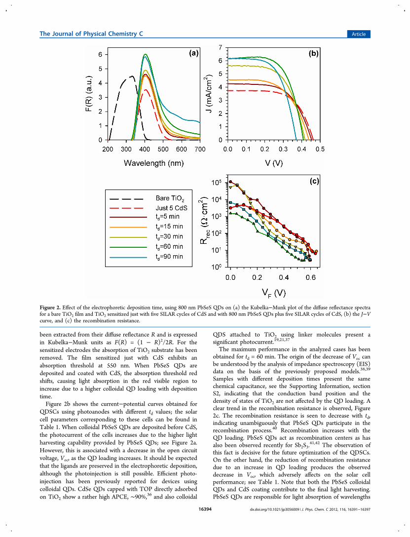
deposition times td have been investigated. Hereafter, todistinguish among the different QD sizes analyzed after the QDtype (PbS or PbSeS), we will add the wavelength of the firstexcitonic absorption peak. Figure 2a presents the absorption, inthe allowed range of our experimental setup, of differentlysensitized TiO2 films: a bare TiO2 film, a film sensitized justwith five SILAR cycles of CdS, and a film sensitized with 800nm PbSeS QDs plus five SILAR cycles of CdS at differentdeposition times. The absorption of the different samples has
Table 2. Solar Cell Parameters of QDSCs Prepared Employing QDs of Different Types and Sizes:a Open Circuit Voltage, Voc,Short Circuit Current, Jsc, Fill Factor, FF, and Photovoltaic Conversion Efficiency, η
aAll the samples present the same electrophoresis deposition time, 60 min, and CdS/ZnS coating, five and two SILAR cycles, respectively, except thelast one with nine and two SILAR cycles. A sample prepared just with nine SILAR cycles of CdS is included for comparison.
Figure 1. SEM analysis of a nanostructured TiO2 sensitized with PbSeS QDs, td = 60 min. The central picture of a photoanode cross section issurrounded by a magnified image and elemental maps of the three square boxes in the central picture. Elemental maps display the Ti, O, Pb, Se, andS spatial elemental distribution.
The Journal of Physical Chemistry C Article
dx.doi.org/10.1021/jp3056009 | J. Phys. Chem. C 2012, 116, 16391−1639716393
been extracted from their diffuse reflectance R and is expressedin Kubelka−Munk units as F(R) = (1 − R)2/2R. For thesensitized electrodes the absorption of TiO2 substrate has beenremoved. The film sensitized just with CdS exhibits anabsorption threshold at 550 nm. When PbSeS QDs aredeposited and coated with CdS, the absorption threshold redshifts, causing light absorption in the red visible region toincrease due to a higher colloidal QD loading with depositiontime.Figure 2b shows the current−potential curves obtained for
QDSCs using photoanodes with different td values; the solarcell parameters corresponding to these cells can be found inTable 1. When colloidal PbSeS QDs are deposited before CdS,the photocurrent of the cells increases due to the higher lightharvesting capability provided by PbSeS QDs; see Figure 2a.However, this is associated with a decrease in the open circuitvoltage, Voc, as the QD loading increases. It should be expectedthat the ligands are preserved in the electrophoretic deposition,although the photoinjection is still possible. Efficient photo-injection has been previously reported for devices usingcolloidal QDs. CdSe QDs capped with TOP directly adsorbedon TiO2 show a rather high APCE, ∼90%,36 and also colloidal
QDS attached to TiO2 using linker molecules present asignificant photocurrent.19,21,37
The maximum performance in the analyzed cases has beenobtained for td = 60 min. The origin of the decrease of Voc canbe understood by the analysis of impedance spectroscopy (EIS)data on the basis of the previously proposed models.38,39
Samples with different deposition times present the samechemical capacitance, see the Supporting Information, sectionS2, indicating that the conduction band position and thedensity of states of TiO2 are not affected by the QD loading. Aclear trend in the recombination resistance is observed, Figure2c. The recombination resistance is seen to decrease with td,indicating unambiguously that PbSeS QDs participate in therecombination process.40 Recombination increases with theQD loading. PbSeS QDs act as recombination centers as hasalso been observed recently for Sb2S3.
41,42 The observation ofthis fact is decisive for the future optimization of the QDSCs.On the other hand, the reduction of recombination resistancedue to an increase in QD loading produces the observeddecrease in Voc, which adversely affects on the solar cellperformance; see Table 1. Note that both the PbSeS colloidalQDs and CdS coating contribute to the final light harvesting.PbSeS QDs are responsible for light absorption of wavelengths
Figure 2. Effect of the electrophoretic deposition time, using 800 nm PbSeS QDs on (a) the Kubelka−Munk plot of the diffuse reflectance spectrafor a bare TiO2 film and TiO2 sensitized just with five SILAR cycles of CdS and with 800 nm PbSeS QDs plus five SILAR cycles of CdS, (b) the J−Vcurve, and (c) the recombination resistance.
The Journal of Physical Chemistry C Article
dx.doi.org/10.1021/jp3056009 | J. Phys. Chem. C 2012, 116, 16391−1639716394
lower than ∼550 nm, while for wavelengths higher than ∼550nm both PbSeS QDs and CdS contribute to the lightabsorption, but with a higher part from CdS; see Figure 2a.We have also analyzed the effect of QD size in the final solar
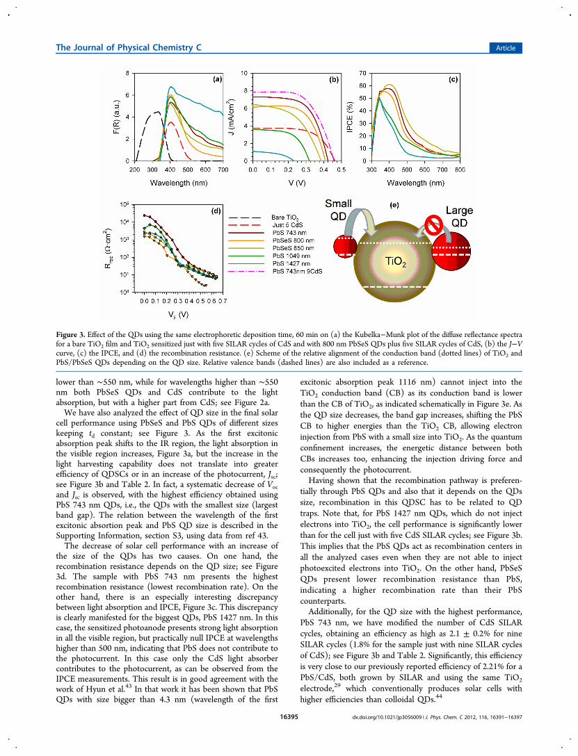
cell performance using PbSeS and PbS QDs of different sizeskeeping td constant; see Figure 3. As the first excitonicabsorption peak shifts to the IR region, the light absorption inthe visible region increases, Figure 3a, but the increase in thelight harvesting capability does not translate into greaterefficiency of QDSCs or in an increase of the photocurrent, Jsc;see Figure 3b and Table 2. In fact, a systematic decrease of Vocand Jsc is observed, with the highest efficiency obtained usingPbS 743 nm QDs, i.e., the QDs with the smallest size (largestband gap). The relation between the wavelength of the firstexcitonic absortion peak and PbS QD size is described in theSupporting Information, section S3, using data from ref 43.The decrease of solar cell performance with an increase of
the size of the QDs has two causes. On one hand, therecombination resistance depends on the QD size; see Figure3d. The sample with PbS 743 nm presents the highestrecombination resistance (lowest recombination rate). On theother hand, there is an especially interesting discrepancybetween light absorption and IPCE, Figure 3c. This discrepancyis clearly manifested for the biggest QDs, PbS 1427 nm. In thiscase, the sensitized photoanode presents strong light absorptionin all the visible region, but practically null IPCE at wavelengthshigher than 500 nm, indicating that PbS does not contribute tothe photocurrent. In this case only the CdS light absorbercontributes to the photocurrent, as can be observed from theIPCE measurements. This result is in good agreement with thework of Hyun et al.43 In that work it has been shown that PbSQDs with size bigger than 4.3 nm (wavelength of the first
excitonic absorption peak 1116 nm) cannot inject into theTiO2 conduction band (CB) as its conduction band is lowerthan the CB of TiO2, as indicated schematically in Figure 3e. Asthe QD size decreases, the band gap increases, shifting the PbSCB to higher energies than the TiO2 CB, allowing electroninjection from PbS with a small size into TiO2. As the quantumconfinement increases, the energetic distance between bothCBs increases too, enhancing the injection driving force andconsequently the photocurrent.Having shown that the recombination pathway is preferen-
tially through PbS QDs and also that it depends on the QDssize, recombination in this QDSC has to be related to QDtraps. Note that, for PbS 1427 nm QDs, which do not injectelectrons into TiO2, the cell performance is significantly lowerthan for the cell just with five CdS SILAR cycles; see Figure 3b.This implies that the PbS QDs act as recombination centers inall the analyzed cases even when they are not able to injectphotoexcited electrons into TiO2. On the other hand, PbSeSQDs present lower recombination resistance than PbS,indicating a higher recombination rate than their PbScounterparts.Additionally, for the QD size with the highest performance,
PbS 743 nm, we have modified the number of CdS SILARcycles, obtaining an efficiency as high as 2.1 ± 0.2% for nineSILAR cycles (1.8% for the sample just with nine SILAR cyclesof CdS); see Figure 3b and Table 2. Significantly, this efficiencyis very close to our previously reported efficiency of 2.21% for aPbS/CdS, both grown by SILAR and using the same TiO2
electrode,29 which conventionally produces solar cells withhigher efficiencies than colloidal QDs.44
Figure 3. Effect of the QDs using the same electrophoretic deposition time, 60 min on (a) the Kubelka−Munk plot of the diffuse reflectance spectrafor a bare TiO2 film and TiO2 sensitized just with five SILAR cycles of CdS and with 800 nm PbSeS QDs plus five SILAR cycles of CdS, (b) the J−Vcurve, (c) the IPCE, and (d) the recombination resistance. (e) Scheme of the relative alignment of the conduction band (dotted lines) of TiO2 andPbS/PbSeS QDs depending on the QD size. Relative valence bands (dashed lines) are also included as a reference.
The Journal of Physical Chemistry C Article
dx.doi.org/10.1021/jp3056009 | J. Phys. Chem. C 2012, 116, 16391−1639716395
■ CONCLUSIONSIn summary, we have sensitized nanostructured TiO2 photo-anodes with colloidal QDs of PbSeS and PbS with differentsizes. We have shown that the electrophoretic depositionmethod can be used advantageously for fast sensitization of thephotoanode with these QDs. CdS coating, deposited by SILAR,protects the colloidal QDs, stabilizing the solar cell perform-ance. A clear effect between QD size and device performance isobserved, obtaining better results for the smallest QDs, withefficiencies as high as 2.1 ± 0.2%. In addition, we have shownunambiguously that QDs act as recombination centers in theseQDSCs. There is plenty of room for the optimization of thesedevices by focusing on reducing recombination through theQD traps. The latter may be possible by improving control ofthe QD properties; further characterization and surfacetreatments seem thus to be crucial. As an example, PbSeS-sensitized photoanodes were here characterized by X-raydiffraction, and the presence of a lead oxide (PbO) phasewas detected, irrespectively of the td (Supporting Information,section S4). Although the origin of oxidation and its final effecton solar cell performance is currently under investigation, thisfinding points out the wide room of improvement of presentlead chalcogenide QDSCs.
■ ASSOCIATED CONTENT*S Supporting InformationFE-SEM micrographs of cross sections of TiO2 and TiO2/PbSSe samples, chemical capacitance of the analyzed cells,correlation between the PbS QD size and wavelength of thefirst excitonic absorption peak, and XRD characterization. Thismaterial is available free of charge via the Internet at http://pubs.acs.org.
■ ACKNOWLEDGMENTSThis work was supported by the Institute of Nanotechnologiesfor Clean Energies, funded by the Generalitat Valenciana underProject ISIC/2012/008. This work was partially supported bythe European Union under Project ORION CP-IP 229036-2,the Ministerio de Educacion y Ciencia of Spain under ProjectsHOPE CSD2007-00007 (Consolider-Ingenio 2010) and JES-NANOSOLAR PLE2009-0042, the Generalitat Valencianaunder Project PROMETEO/2009/058, an NSERC (Canada)strategic project grant, and a McGill University MEDAscholarship. R.T.-Z. acknowledges the support of the ProgramRamon y Cajal of the MICINN. We acknowledge NANOCOfor providing kindly PbSeS QDs.
■ REFERENCES(1) Shockley, W.; Queisser, H. J. J. Appl. Phys. 1961, 32, 510−519.(2) Nozik, A. J. Physica E 2002, 14, 115−200.(3) Schaller, R. D.; Klimov, V. I. Phys. Rev. Lett. 2004, 92, 186601.(4) Ellingson, R. J.; Beard, M. C.; Johnson, J. C.; Yu, P.; Micic, O. I.;Nozik, A. J.; Shabaev, A.; Efros, A. L. Nano Lett. 2005, 5, 865−871.(5) Trinh, M. T.; Houtepen, A. J.; Schins, J. M.; Hanrath, T.; Piris, J.;Knulst, W.; Goossens, A. P. L. M.; Siebbeles, L. D. A. Nano Lett. 2008,8, 1713−1718.
(6) Sambur, J. B.; Novet, T.; Parkinson, B. A. Science 2010, 330, 63−66.(7) Semonin, O. E.; Luther, J. M.; Choi, S.; Chen, H.-Y.; Gao, J.;Nozik, A. J.; Beard, M. C. Science 2011, 334, 1530−1533.(8) O’ Regan, B.; Gratzel, M. Nature 1991, 353, 737−740.(9) Grinis, L.; Dor, S.; Ofir, A.; Zaban, A. J. Photochem. Photobiol., A2008, 198, 52−59.(10) Mora-Sero, I.; Lana-Villarreal, T.; Bisquert, J.; Pitarch, A.;Gomez, R.; Salvador, P. J. Phys. Chem. B 2005, 109, 3371−3380.(11) Islam, M. A.; Xia, Y.; Telesca, D. A., Jr.; Steigerwald, M. L.;Herman, I. P. Chem. Mater. 2004, 16, 49−54.(12) Jia, S.; Banerjee, S.; Herman, I. P. J. Phys. Chem. C 2008, 112,162−171.(13) Islam, M. A.; Herman, I. P. Appl. Phys. Lett. 2002, 80, 3823−3825.(14) Farrow, B.; Kamat, P. V. J. Am. Chem. Soc. 2009, 131, 11124−11131.(15) Zhang, Q.; Xu, T.; Butterfield, D.; Misner, M. J.; Ryu, D. J.;Emrick, T.; Russell, T. P. Nano Lett. 2005, 5, 357−361.(16) Brown, P.; Kamat, P. V. J. Am. Chem. Soc. 2008, 130, 8890−8891.(17) Chen, J.; Lei, W.; Li, C.; Zhang, Y.; Cui, Y.; Wang, B.; Deng, W.Phys. Chem. Chem. Phys. 2011, 13, 13182−13184.(18) Salant, A.; Shalom, M.; Hod, I.; Faust, A.; Zaban, A.; Banin, U.ACS Nano 2010, 4, 5962−5968.(19) Gimenez, S.; Mora-Sero, I.; Macor, L.; Guijarro, N.; Lana-Villarreal, T.; Gomez, R.; Diguna, L. J.; Shen, Q.; Toyoda, T.; Bisquert,J. Nanotechnology 2009, 20, 295204.(20) Robel, I.; Subramanian, V.; Kuno, M.; Kamat, P. V. J. Am. Chem.Soc. 2006, 128, 2385−2393.(21) Mora-Sero, I.; Gimenez, S.; Fabregat-Santiago, F.; Gomez, R.;Shen, Q.; Toyoda, T.; Bisquert, J. Acc. Chem. Res. 2009, 42, 1848−1857.(22) Hodes, G. J. Phys. Chem. C 2008, 112, 17778−17787.(23) Lee, H. J.; Leventis, H. C.; Moon, S.-J.; Chen, P.; Ito, S.; Haque,S. A.; Torres, T.; Nuesch, F.; Geiger, T.; Zakeeruddin, S. M.; et al. Adv.Funct. Mater. 2009, 19, 2735−2742.(24) Ma, B.; Wang, L.; Dong, H.; Gao, R.; Geng, Y.; Zhu, Y.; Qiu, Y.Phys. Chem. Chem. Phys. 2011, 13, 2656−2658.(25) Snaith, H. J.; Stavrinadis, A.; Docampo, P.; Watt, A. A. W. Sol.Energy 2011, 85, 1283−1290.(26) Acharya, K. P.; Khon, E.; O’Conner, T.; Nemitz, I.; Klinkova, A.;Khnayzer, R. S.; Anzenbacher, P.; Zamkov, M. ACS Nano 2011, 5,4953−4964.(27) Im, S. H.; Kim, H.-J.; Kim, S. W.; Kimb, S.-W.; Seok, S. I. EnergyEnviron. Sci. 2011, 4, 4181−4186.(28) Lee, H. J.; Chen, P.; Moon, S.-J.; Sauvage, F.; Sivula, K.; Bessho,T.; Gamelin, D. R.; Comte, P.; Zakeeruddin, S. M.; Seok, S. I.; et al.Langmuir 2009, 25, 7602−7608.(29) Braga, A.; Gimenez, S.; Concina, I.; Vomiero, A.; Mora-Sero, I. J.Phys. Chem. Lett. 2011, 2, 454−460.(30) Samadpour, M.; Boix, P. P.; Gimenez, S.; Iraji Zad, A.;Taghavinia, N.; Mora-Sero, I.; Bisquert, J. J. Phys. Chem. C 2011, 115,14400−14407.(31) Hossain, M. A.; Koh, Z. Y.; Wang, Q. Phys. Chem. Chem. Phys.2012, 14, 7367−7374.(32) Zhou, N.; Chen, G.; Zhang, X.; Cheng, L.; Luo, Y.; Li, D.;Meng, Q. Electrochem. Commun. 2012, 20, 97−100.(33) Kinder, E.; Moroz, P.; Diederich, G.; Johnson, A.; Kirsanova,M.; Nemchinov, A.; O’Connor, T.; Roth, D.; Zamkov, M. J. Am. Chem.Soc. 2011, 133, 20488−20499.(34) Yang, Y.; Rodríguez-Cordoba, W.; Xiang, X.; Lian, T. Nano Lett.2012, 12, 303−309.(35) Ma, W.; Luther, J. M.; Zheng, H.; Wu, Y.; Alivisatos, A. P. NanoLett. 2009, 9, 1699−1703.(36) Gimenez, S.; Xu, X.; Lana-Villarreal, T.; Gomez, R.; Agouram,S.; Munoz-Sanjose; Mora-Sero, I. J. Appl. Phys. 2010, 108, 064310.(37) Watson, D. F. J. Phys. Chem. Lett. 2010, 1, 2299−2309.
The Journal of Physical Chemistry C Article
dx.doi.org/10.1021/jp3056009 | J. Phys. Chem. C 2012, 116, 16391−1639716396