+ All Categories
Home > Documents > COLOR LASERJET 3500N - M.K. Electronic Color LaserJet 3500n printer HP Parts Reference Guide™ 250...

COLOR LASERJET 3500N - M.K. Electronic Color LaserJet 3500n printer HP Parts Reference Guide™ 250...

Date post: 21-Mar-2018
Category:
Upload: trinhhuong
View: 216 times
Download: 0 times
Share this document with a friend
30
HP Color LaserJet 3500n printer HP Parts Reference Guide™ www.hp.com/go/hpparts 250 Sheet Cassette Pad 1 RC1-0954-000CN Separation pad assembly in front portion of 250 sheet tray Plate 2 RB2-3003-040CN Plate end - Movable end plate at back of Tray 2 paper cassette Spring 3 RS6-2021-000CN Pad spring - Provides tension for separation pad on front of paper tray Tray 4 RM1-0470-000CN 250 Sheet tray - Tray 2 paper holding cassette assembly 250 Sheet Tray Cable 5 RM1-0496-000CN Option connecting cable - 6 RM1-0497-000CN Lower frame cable - Cable under 250 sheet tray/Tray 2 Connector 7 VS1-6176-006CN 250/500 sheet feeder connector Cover 8 RC1-2237-000CN Lower frame cover - Bottom cover for 250 sheet/Tray 2 Foot 9 RC1-2428-000CN Rear support foot - Black plastic support foot for rear of Tray 2 - Two used 10 RM1-0459-000CN Front support foot - Black plastic support foot for front of Tray 2 - Two used Ground Strap 11 RC1-1508-000CN Grounding plate - Ground contact on front inside of right side 250 sheet/Tray 2 cassette guide 12 RC1-1637-000CN Grounding plate - Ground connection on bottom of left cassette guide assembly Guide 13 RC1-1306-000CN Cable guide - Cable guide on right side of 250 sheet/Tray 2 frame 14 RC1-1491-000CN Left cassette guide - Left side cassette guide for 250 sheet Tray 2 15 RC1-1492-000CN Right cassette guide - Right side cassette guide for 250 sheet Tray 2 16 RC1-2322-000CN Cable guide - Cable guide on right rear portion of lower frame assembly - Black plastic 90 degree bend guide 17 RC1-2323-000CN Cable guide - Cable guide on left middle portion of lower frame assembly - Black plastic double 90 degree bend guide RM1-0736-000CN Right cassette guide - Right side cassette guide for 250 sheet Tray 2 Mount 19 RC1-1511-000CN Solenoid mount - Pad 20 RM1-0739-000CN Separation pad assembly - Tray 2 paper separation pad assembly - Includes pad holder and separation pad Plate 21 RC1-1509-000CN Grounding plate - Ground contact on front outside of right side 250 sheet/Tray 2 cassette guide Accessories Cable (Interface) C6518A Universal serial bus (USB) interface cable - Type 'A' connector to type 'B' connector - 2.0m (6.6ft) long Cleaning Supplies 5090-3379 Toner cleaning cloth - Specially treated cloth for absorbing toner (1 per package) - Ideal for clening up toner spills Manual Q1321-90930 Color LaserJet 3500 and 3700 series service manual External Case Parts Cover 25 RC1-1563-000CN Right side of printer cover - Does not include logo plate 26 RC1-1565-000CN Rear cover - Small cover above rear paper output tray 27 RC1-1566-000CN Rear jam access door - Small access door above small rear cover over rear paper output tray © 2004 Hewlett-Packard 1 www MK-Electronic de
Transcript

HP Color LaserJet 3500n printer

HP Parts Reference Guide™www.hp.com/go/hpparts

250 Sheet Cassette

Pad

1 RC1-0954-000CN Separation pad assembly in front portion of 250 sheet tray

Plate

2 RB2-3003-040CN Plate end - Movable end plate at back of Tray 2 paper cassette

Spring

3 RS6-2021-000CN Pad spring - Provides tension for separation pad on front of paper tray

Tray

4 RM1-0470-000CN 250 Sheet tray - Tray 2 paper holding cassette assembly

250 Sheet Tray

Cable

5 RM1-0496-000CN Option connecting cable -

6 RM1-0497-000CN Lower frame cable - Cable under 250 sheet tray/Tray 2

Connector

7 VS1-6176-006CN 250/500 sheet feeder connector

Cover

8 RC1-2237-000CN Lower frame cover - Bottom cover for 250 sheet/Tray 2

Foot

9 RC1-2428-000CN Rear support foot - Black plastic support foot for rear of Tray 2 - Two used

10 RM1-0459-000CN Front support foot - Black plastic support foot for front of Tray 2 - Two used

Ground Strap

11 RC1-1508-000CN Grounding plate - Ground contact on front inside of right side 250 sheet/Tray 2 cassette guide

12 RC1-1637-000CN Grounding plate - Ground connection on bottom of left cassette guide assembly

Guide

13 RC1-1306-000CN Cable guide - Cable guide on right side of 250 sheet/Tray 2 frame

14 RC1-1491-000CN Left cassette guide - Left side cassette guide for 250 sheet Tray 2

15 RC1-1492-000CN Right cassette guide - Right side cassette guide for 250 sheet Tray 2

16 RC1-2322-000CN Cable guide - Cable guide on right rear portion of lower frame assembly - Black plastic 90 degree bend guide

17 RC1-2323-000CN Cable guide - Cable guide on left middle portion of lower frame assembly - Black plastic double 90 degree bend guide

RM1-0736-000CN Right cassette guide - Right side cassette guide for 250 sheet Tray 2

Mount

19 RC1-1511-000CN Solenoid mount -

Pad

20 RM1-0739-000CN Separation pad assembly - Tray 2 paper separation pad assembly - Includes pad holder and separation pad

Plate

21 RC1-1509-000CN Grounding plate - Ground contact on front outside of right side 250 sheet/Tray 2 cassette guide

Accessories

Cable (Interface)

C6518A Universal serial bus (USB) interface cable - Type 'A' connector to type 'B' connector - 2.0m (6.6ft) long

Cleaning Supplies

5090-3379 Toner cleaning cloth - Specially treated cloth for absorbing toner (1 per package) - Ideal for clening up toner spills

Manual

Q1321-90930 Color LaserJet 3500 and 3700 series service manual

External Case Parts

Cover

25 RC1-1563-000CN Right side of printer cover - Does not include logo plate

26 RC1-1565-000CN Rear cover - Small cover above rear paper output tray

27 RC1-1566-000CN Rear jam access door - Small access door above small rear cover over rear paper output tray

© 2004 Hewlett-Packard 1

www MK-E

lectro

nic de

HP Color LaserJet 3500n printer

HP Parts Reference Guide™www.hp.com/go/hpparts

External Case Parts

Cover

28 RC1-1574-000CN MP/Tray 1 cover - Front cover for drop down MP/Tray 1

29 RC1-2296-000CN Hinge cover - Covers hinge on bottom of front cover assembly - 2 used

30 RM1-0463-000CN Front cover assembly - Front of printer including drop down MP/Tray 1 assembly

31 RM1-0465-000CN Top cover assembly - Top of printer with face down paper output

32 RM1-0466-000CN Left side plastic cover for printer - DIMM access side

33 RM1-0467-000CN Left front cover assembly - Left front corner plastic with control panel

Extender

34 RC1-1555-000CN Flip-up tray extender - Flip-up tab in middle of top paper output tray - Allows better support for legal size paper

Overlay

Q1321-67901 Control Panel Overlay (French)

Q1321-67902 Control Panel Overlay (German)

Q1321-67903 Control Panel Overlay (Italian)

Q1321-67904 Control Panel Overlay (Spanish)

Q1321-67905 Control Panel Overlay (Danish)

Q1321-67906 Control Panel Overlay (Netherlands)

Q1321-67907 Control Panel Overlay (Finnish)

Q1321-67908 Control Panel Overlay (Norwegian)

Q1321-67909 Control Panel Overlay (Portuguese)

Q1321-67910 Control Panel Overlay (Swedish)

Q1321-67911 Control Panel Overlay (Czech)

Q1321-67912 Control Panel Overlay (Hungarian)

Q1321-67913 Control Panel Overlay (Polish)

Q1321-67914 Control Panel Overlay (Russian)

Q1321-67915 Control Panel Overlay (Polish)

Q1321-67916 Control Panel Overlay (Arabic)

Q1321-67917 Control Panel Overlay (Greek)

Q1321-67918 Control Panel Overlay (Hebrew)

Q1321-67919 Control Panel Overlay (Japanese)

Q1321-67920 Control Panel Overlay (Korean)

Q1321-67921 Control Panel Overlay (Simplified Chinese)

Q1321-67922 Control Panel Overlay (Traditional Chinese)

Panel

57 RC1-1562-000CN Side cover - Panel on left side of printer with HP logo

Plate

58 RC1-1600-000CN Logo plate - Plate with HP logo that attaches to right side of printer

Rod

59 RM1-0443-000CN Left front rod assembly - Part of left side front door hinge - Disengages color cartridges when front door opens

60 RM1-0444-000CN Right front rod assembly - Part of right side front door hinge - Disengages Image Transfer Belt (ITB) when front door opens

Tray Assembly

61 RM1-0468-000CN Face-up output tray assembly - Drop down paper output tray on rear of printer

Internal Components

Arm

62 RC1-1169-000CN Left drum lock arm - Black plastic drum lock arm for Cyan cartridge

63 RC1-1170-000CN Left drum lock arm - Black plastic drum lock arm for black toner cartridge

64 RC1-1175-000CN Interlock switch arm - Located at top right corner of printer frame

65 RC1-1362-000CN Right drum lock arm - Right side lock arm for Cyan toner cartridge

© 2004 Hewlett-Packard 2

www MK-E

lectro

nic de

HP Color LaserJet 3500n printer

HP Parts Reference Guide™www.hp.com/go/hpparts

Internal Components

Arm

66 RC1-1545-000CN Right drum lock arm - Right side lock arm for Magenta toner cartridge

67 RC1-1622-000CN Left drum lock arm - Black plastic drum lock arm for Yellow cartridge

68 RC1-1623-000CN Left drum lock arm - Black plastic drum lock arm for Magenta cartridge

69 RC1-1626-000CN Left stopper arm - White plastic arm on inside top left inside frame

70 RC1-1627-000CN Left stopper arm -

RC1-2339-000CN Right stopper arm

Base

72 RC1-2235-000CN DC Controller board mounting base

Bushing

73 RC1-1218-000CN Gear bushing - White plastic bushing for 29 tooth gears on front right inside mounting plate - Four used

74 RC1-1243-000CN Bushing - White plastic gear bushing

75 RC1-1244-000CN Bushing - Four bushings used on outside drive plate - One each

76 RC1-1270-000CN Clutch bushing - Bushing between registration clutch CL1 and mount - On right side of printer

77 RC1-1310-000CN Bushing - White plastic gear bushing

78 RC1-1630-000CN Gear bushing - Bushing for 25 tooth gear on right side of printer

Button

79 RC1-1593-000CN Test print connecting block - Engine test button on left side of printer

Cable

80 RK2-0163-000CN TM FFC cable - Connects DC controller board to Memory controller board

81 RK2-0164-000CN Laser scanner cable - Longer cable of the two cables that run from DC controller to lower PC board on Laser scanner assembly

82 RK2-0165-000CN Laser scanner cable - Shorter cable from DC controller to upper board on Laser scanner assembly

83 RK2-0179-000CN Ribbon cable - Connects DC controller board to Formatter board

84 RM1-0477-000CN Sensor cable - Cable for Feed Delivery sensor PS8

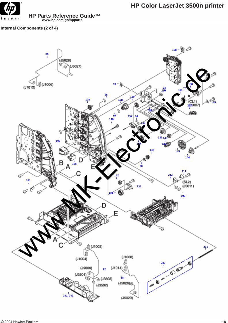
85 RM1-0482-000CN CPR connecting cable - From DC controller to PS12/Color Misregistration sensor

RM1-0483-000CN Formatter power supply cable - From Low Voltage power supply to DC controller board

87 RM1-0485-000CN High voltage cable - From high voltage PC board to DC controller board

88 RM1-0488-000CN Front left cable - DC Controller to PS5/Media sensor

89 RM1-0489-000CN Operation panel cable - Cable that connects to control panel

90 RM1-0493-000CN Environment sensor cable - Cable between humidity sensor and DC Controller board

91 RM1-0495-000CN Main cable - Large cable connected to DC controller board

92 RM1-0498-000CN Formatter power supply cable - From Low Voltage power supply to DC controller board

Clip

93 WT2-5841-000CN Cable clip - Push in white plastic stand off for cables - Push in stand off for cables on right side of printer - Nine used on right side

94 XD9-0134-000CN E-ring retainer clip

95 XD9-0135-000CN Shaft E-clip - Developing disengaging drive shaft E-clip

96 XD9-0136-000CN Retaining E-ring

97 XD9-0137-000CN E-Type retainer ring - E-clip - E-ring retainer for 45 tooth/25 tooth cluster gear at right rear of printer

Clutch

98 Q1321-67925 Electromagnetic clutch - K-drive development clutch - Clutch CL2

99 RB2-6324-000CN Clutch -

100 RK2-0176-000CN Developing engaging drive clutch - Clutch CL3

101 RK2-0247-000CN Electromagnetic clutch - Registration clutch - CL1

Connector

102 VS1-5057-002CN SL2/Tray 2 solenoid electrical connector

103 VS1-7207-016CN 16 pin connector - Intermediate connector used between DC controller board and multiple sensors/solenoids

© 2004 Hewlett-Packard 3

www MK-E

lectro

nic de

HP Color LaserJet 3500n printer

HP Parts Reference Guide™www.hp.com/go/hpparts

Internal Components

Contact Assembly

104 RM1-0440-000CN Electrical connector for fuser assembly - Located on lower left side of printer frame - Includes cable from DC controller board

105 RM1-0445-000CN Transfer contact assembly - Electrical contact assembly for ITB (Image Transfer Belt)

106 RM1-0446-000CN Developing contact assembly - Large black plastic frame on left side with multiple contact springs

Cover

107 RC1-1353-000CN Motor cover - Black plastic cover for feed motor M1

108 RC1-1488-000CN Connector cover - Black plastic connector cover for feed motor M1

109 RC1-1605-000CN Screw cover - Clear plastic cover with three bubbles to protect screw heads - Peel off backing adhesive for mounting

110 RC1-1640-000CN Laser shutter cover - Black plastic guides mounted to metal back of printer - Four used

111 RC1-1665-000CN Cover - Solenoid cover for SL2 on right front of printer

112 RC1-2236-000CN Controller cover - DC Controller board cover

113 RC1-2364-000CN Formatter cable cover - Metal cover for the ribbon cable between the formatter and the DC Controller board

114 RC1-2379-000CN Cover shield - Cover shield for registration clutch CL1 and mount

Damper

115 RC1-1038-000CN Tray 1/MP Tray damper - Dampens movement on right side of drop down Tray 1 - White plastic gear mounted on a black plastic arm

116 RC1-1572-000CN Left damper unit - Round white pivot point for left side front door - Provides friction for front door opening

117 RC1-1573-000CN Right damper unit - Round white pivot point for right side front door - Provides friction for front door opening

Drive Assembly

118 RM1-0415-040CN Image drive assembly - Vertical gear drive assembly on front right side of printer

119 RM1-0419-000CN Drive assembly - Developer disengaging planetary gear drive assembly - Located on lower front right side of printer

120 RM1-0434-000CN Developing engaging drive assembly -

Duct

121 RC1-1345-000CN Upper left rear air duct - Housing for exhaust fan FM1

122 RC1-1350-000CN Upper left rear fan duct to printer frame mount

123 RC1-1354-000CN Air duct - Plastic air duct below laser scanner assembly

Fan

RK2-0017-000CN Exhaust fan - Fan at upper right rear side of printer - FM1

125 RK2-0153-000CN Cooling fan - Fan FM1 - Located on upper left rear of printer

Flag

126 RC1-1330-000CN Sensor flag - Flag that activates sensor PS14

Gear

127 RC1-1213-000CN Cluster gear - 86-tooth/23-tooth gear - Mounted in gear assembly on right rear side of printer

128 RC1-1224-000CN Cluster gear - 50 tooth/90 tooth gear mounted in gear assembly on right side of printer

129 RC1-1229-000CN Cluster gear - 90-tooth/28-tooth gear - Mounted in gear assembly on right rear side of printer

130 RC1-1230-000CN 74 tooth gear - Black plastic 74 tooth gear mounted in gear assembly on right side of printer - Four used

131 RC1-1231-000CN 59 tooth gear - 59 tooth gear mounted in gear assembly on right side of printer - Two used

132 RC1-1233-000CN 69 tooth gear - 69 tooth gear mounted in gear assembly on right side of printer

133 RC1-1234-000CN 29 tooth gear - White plastic toner drive gear mounted in gear assembly on right side of printer - Four used

134 RC1-1252-000CN Cluster gear - 120 tooth/17 tooth - Large gear in developer disengaging drive assembly

135 RC1-1281-000CN 39 tooth gear - 39 tooth gear mounted in gear assembly on right side of printer

136 RC1-1283-000CN Cluster gear - 26 tooth/47 tooth gear mounted in gear assembly on right side of printer

137 RC1-1284-000CN Cluster gear - 31 tooth/19 tooth gear mounted in gear assembly on right side of printer

138 RC1-1286-000CN Cluster gear - 45 tooth/25 tooth gear mounted in gear assembly on right side of printer

139 RC1-1288-000CN 38 tooth gear - 38 tooth gear mounted in gear assembly on right side of printer

140 RC1-1291-000CN Cluster gear - 104 tooth/25 tooth gear mounted in gear assembly on right side of printer

141 RC1-1294-000CN 43 tooth gear - 43 tooth gear mounted in gear assembly on right side of printer

© 2004 Hewlett-Packard 4

www MK-E

lectro

nic de

HP Color LaserJet 3500n printer

HP Parts Reference Guide™www.hp.com/go/hpparts

Internal Components

Gear

142 RC1-1295-000CN 27 tooth gear - 27 tooth gear mounted in gear assembly on right side of printer

143 RC1-1298-000CN Cluster gear - 26 tooth/22 tooth/20 tooth gear mounted in gear assembly on right side of printer

144 RC1-1300-000CN Cluster gear - 54 tooth/17 tooth gear mounted in gear assembly on right side of printer

145 RC1-1302-000CN 79 tooth gear - Large gear mounted in gear assembly on right side of printer

146 RC1-1493-000CN 20 tooth gear - 20 tooth gear mounted in gear assembly on right side of printer

147 RC1-1497-000CN 25 tooth gear - Mounted in gear assembly on right side of printer

148 RC1-3240-000CN 74 tooth gear - White plastic 74 tooth gear mounted in gear assembly on right side of printer

Guide

149 RC1-1156-000CN Left guide rod - Front inside portion of white plastic swing guide rod assembly

150 RC1-1181-000CN Cable guide - Located in front of DC Controller board

151 RC1-1342-000CN Wire harness guide - Protects wire harness that goes through lower right front corner of printer

RC1-1661-000CN Right front swing rail - White plastic guide attached to right side of chassis below Mulitpurpose Tray hinge link

153 RC1-2334-000CN Cable guide - Guide for cable in lower right front corner

154 RM1-0437-000CN Right side swing frame assembly - Right toner cartridge guide - Black plastic with cartridge guide on right side with color labels

155 RM1-0438-000CN Right swing guide assembly - Black plastic guide on lower right side

156 RM1-0439-000CN Left side swing frame assembly - Black plastic frame with cartridge guide on right side with cartridge electricalcontacts

Holder

157 RC1-1287-000CN Gear holder - Pivot gear holder for 104/25 cluster gear and

158 RC1-1329-000CN Sensor holder - Holder for developing engaging sensor PS14

159 RC1-1343-000CN PC board holder - Small plastic holder for memory controller PC board assembly

160 RC1-1496-000CN Sensor holder - Holder for duplexing paper feed sensor (PS10) assembly

161 WT2-0507-000CN Cable holder - Secures cable at left rear side near DC controller board - Small white plastic cable support

162 WT2-5738-000CN Cable holder - Secures cable at left front side near DC controller board - White plastic stand-off/holder

163 WT2-5754-000CN Cable holder - Secures cable at top of DC controller board - Large white plastic cable support

Label

164 RC1-2422-000CN High temperature warning label - Applied to air duct above fuser assembly at bottom rear of printer

Lens

165 RC1-1050-000CN Lens - Optical lens used with toner hopper full (PS13) sensor - Two used

Lever

166 RC1-1176-000CN Interlock switch lever - Lever that activates front door switch SW1 - Connected to left side of front door releasehandle square shaft

167 RC1-1247-000CN ITB coupling lever - Connected to right side of front door release handle square shaft

168 RC1-1248-000CN Intermediate Transfer Belt (ITB) coupling lever - White plastic lever with eight gear teeth

169 RC1-1647-000CN Left swing lock lever - Swing lock lever just below Yellow toner cartridge

Link

170 RC1-1575-000CN Left hinge link - Hinge link that supports the left side of drop down MP Tray cover

RC1-1576-000CN Right hinge link - Hinge link that supports the right side of drop down MP Tray cover

Lock

172 RC1-1148-000CN Right side swing lock - Black plastic swing guide arm lever

173 RC1-1246-000CN Right drum lock arm - Right side lock arm for Yellow toner cartridge

Motor

174 RK2-0137-000CN Delivery motor - Motor M2

175 RK2-0138-000CN Paper feed motor - Located on lower left front of printer - Motor M1

176 RK2-0139-000CN Electric motor - Transfer roller engaging motor - Motor M5

177 RM1-0733-000CN Drum motor - Provides power to turn cartridge drums - Motor M3

178 RM1-0737-000CN Developing motor - Located on upper right side inside frame - Motor M4

© 2004 Hewlett-Packard 5

www MK-E

lectro

nic de

HP Color LaserJet 3500n printer

HP Parts Reference Guide™www.hp.com/go/hpparts

Internal Components

Mount

179 RC1-1049-000CN Sensor holder - Mount for toner hopper full sensor (PS13) and associated lens

180 RC1-1186-000CN Clutch mount - Registration clutch (CL1) mount plate

181 RC1-1355-000CN Mounting plate -

RL1-0203-000CN Solenoid mount -

Pad

183 RC1-2330-000CN Pad - Small black foam piece that provides cushioning for cartridge arms - Three used

184 RC1-2331-000CN Cushion pad - Small black foam rubber rectangle shaped pad

Pivot

185 RC1-1649-000CN Grounding plate - Ground for registration clutch CL1

Plate

186 RC1-1151-000CN Contact plate - Grounding plate on left side for Yellow toner cartridge

187 RC1-1152-000CN Contact plate - Grounding plate on left side for Black toner cartridge

188 RC1-1153-000CN Contact plate - Grounding plate on left side for Cyan toner cartridge

189 RC1-1155-000CN Contact plate - Grounding plate on left side for Magenta toner cartridge

190 RC1-1242-000CN Gear reinforcement plate - Mounting plate for 29-tooth gears on front right inside mounting plate - Four used

191 RC1-1277-000CN Metal gear mounting plate - Vertical piece the supports gear assembly on outside of right side printer frame

192 RC1-1348-000CN DC controller board mounting plate

193 RC1-1349-000CN Shield plate - Metal plate that covers memory controller board

194 RC1-1602-000CN Right rear corner top cover support

195 RC1-1603-000CN Right joint plate - Top right rear metal cover support

196 RC1-1629-000CN Grounding plate

197 RC1-2294-000CN Grounding plate - Metal grounding contact on inside lower front right side

198 RC1-2385-000CN Clutch shield plate - Shield plate for clutch CL2 on image drive assembly

199 RL1-0189-000CN Mounting plate - Pivot point for ITB coupling lever

200 RL1-0193-000CN Drive plate - Paper feeder gear drive assembly plate - Metal plate on lower right side of printer that gears for paper feeder drive are attached to

Rail

201 RC1-1641-000CN Left rear swing rail - Rear portion of left swing rail

202 RC1-1642-000CN Left front swing rail - White plastic left inside swing rail

203 RC1-1662-000CN Right rear swing rail -

Retainer

204 RC1-2437-000CN Cable retaining sheet - Black dense foam rubber that provides tension for connector

Rod

205 RC1-1347-000CN Power switch rod - Mechanical link between power switch on front of printer and DC controller board

206 RM1-0441-000CN Left swing rod assembly - Plastic arm with metal insert

207 RM1-0442-000CN Right swing rod assembly

Sensor

208 RM1-0509-000CN Sensor assembly - Waste toner hopper full sensor (PS13) assembly - Does not include lenses or mounting plate

209 WG8-5362-000CN Optical sensor - Optical sensors used in pick-up/feed assembly - Used for PS1, PS4 and PS16

210 WP2-5156-000CN Humidity sensor unit - Located upper left rear portion of printer - Above fan FM1

Shaft

211 RC1-1500-000CN Drive shaft - Roller shaft that supports the paper cassette pick-up rollers

Solenoid

212 RK2-0141-000CN Electromechanical solenoid - Tray 1 Pickup solenoid - Engages Tray 1 pickup roller - SL1

Spring

213 RC1-1149-000CN Tension spring - Provides tension for right side swing lock

214 RC1-1177-000CN Grounding spring - Ground spring located on left guide rod assembly

© 2004 Hewlett-Packard 6

www MK-E

lectro

nic de

HP Color LaserJet 3500n printer

HP Parts Reference Guide™www.hp.com/go/hpparts

Internal Components

Spring

215 RC1-1184-000CN Tension spring - Provides tension for top left drum lock arm

216 RC1-1185-000CN Tension spring - Provides tension for black plastic drum lock arms

217 RC1-1259-000CN Tension spring - Provides tension for right drum lock arm - Four used

218 RC1-1260-000CN Tension spring - Provides tension for ITB (Image Transfer Belt) coupler at top right front of printer frame

219 RC1-1292-000CN Tension spring - Provides tension for gear holder that holds 104/25 tooth cluster gear

220 RC1-1328-000CN Torsion spring - Provides tension for sensor flag in center frame assembly

221 RC1-1407-000CN Tension spring - Provides tension for MP/Tray 1

222 RC1-1515-000CN Tension spring - Provides tension for pickup gear assembly on right side

223 RC1-1537-000CN Grounding spring - Grounding spring for right drum lock arm

224 RC1-1548-000CN Provides tension for rigth stopper arm - Three used

225 RC1-1628-000CN Tension spring - Provides tension to the color drum lock arms on left side - Three used

226 RC1-1648-000CN Tension spring - Provides tension for left swing lock lever

Stop

227 RC1-1546-000CN Right arm stopper

228 RC1-1607-000CN Front right hinge stop - Metal stop on right front frame bottom for front door hinge

229 RL1-0215-000CN Front left hinge stop - Metal stop on left front frame bottom for front door hinge

Strap

230 RC1-1625-000CN Damper strap - Three used

Support

231 RC1-1158-000CN Left front cover rod support - Attaches above front cover hinge - Attachment point for toner cartridge disengagment rod on left side

232 RC1-1159-000CN Right front cover rod support - Attaches above front cover hinge on right side - Attachment point for belt drive disengagement rod on right side

233 RL1-0217-000CN Gear support - Pickup roller drive gears support - Piece that the 43 tooth and 27 tooth gears are mounted to on lower right front of printer

Switch

234 RK2-0150-000CN Microswitch - Front door open switch on top front left of printer - Switch SW1

Washer

XD1-1108-229CN Counter measure washer - Small brass washer installed on black toner cartridge clutch shaft between 90 tooth gearand clutch CL2 - For serial numbers CNBRC00000 through CNBRS00763

Logic/Control Electronics

PC Board

236 Q1319-69001 Formatter board assembly - For LaserJet 3500REQUIRES RETURN OF DEFECTIVE PART

Q1319-67901 New Part for Q1319-69001

237 RM1-0505-000CN High voltage power supply assembly - Large PC board located on left side of printer

238 RM1-0508-000CN Memory controller PC board assembly - E-label and waste toner full controller

239 RM1-0510-000CN DC controller board assembly - Located on rear lower left of printer - For LJ3500

240 RM1-0511-000CN Operation panel assembly - Control panel PC board

241 RM1-1213-000CN Formatter board assembly - For LaserJet 3500

Power Supply

242 RK2-0157-000CN Low Voltage power supply - Located on bottom left side of printer - 110 volt

243 RK2-0158-000CN Low Voltage power supply - Located on bottom left side of printer - 220 volt

Paper Path Parts

Extension

244 RC1-2318-000CN MP/Tray 1 pull out extension - Flip out paper support extension for MP/Tray 1

245 RC1-2319-000CN Small pull out extension on the MP/Tray 1 - This is the small pull out paper support extension that is attached to the middle of the flip out extension of the MP/Tray 1

© 2004 Hewlett-Packard 7

www MK-E

lectro

nic de

HP Color LaserJet 3500n printer

HP Parts Reference Guide™www.hp.com/go/hpparts

Paper Path Parts

Flag

246 RC1-1456-000CN Sensor lever - Tray 1 paper sensor flag - Mechanical link for photosensor PS1

247 RC1-1514-000CN Sensor lever - Lever that activates dulexing paper feed sensor (PS10)

Fusing Assembly

Q3655A Fuser assembly - Paper fusing assembly for 3500 and 3700 series Color LaserJet - 110-127V

Q3656A Fuser assembly - Paper fusing assembly for 3500 and 3700 series Color LaserJet - 220-240V

250 RM1-0428-000CN Fusing assembly - 110V

251 RM1-0430-000CN Fusing assembly - 220V

Guard

252 RM1-0460-000CN Paper feed guide assembly - Paper guide assembly in bottom of printer

Laser Assembly

253 RM1-1142-000CN Laser scanner assembly - All four scanners in one assmbly at back of printer

Pad

254 RC1-0939-000CN Separation pad - Tray 1 separation pad - Does not include holder

Roller

255 RC1-1535-000CN Pick-up roller - Tray 1/MP Tray pickup roller

Roller Assembly

256 RM1-0469-000CN Face-down delivery assembly - Large black plastic assembly on back of printer

257 RM1-0731-020CN Cassette pickup roller assembly - Blue plastic pickup roller used in Tray 3

258 RM1-0740-000CN Transfer roller assembly - T2 transfer roller, bushings and holders

Sensor Mechanism

259 RM1-0451-000CN Color mis-registration sensor assembly - Assembly that holds photosensor PS12

260 RM1-0452-000CN Media sensor assembly - Paper type sensor assembly - Includes sensor PS5

Spring

261 RC1-1464-000CN Torsion spring - Provides pressure for Tray 1 paper sensor flag

Transfer Assembly

RM1-0420-000CN Image transfer assembly - Includes the support frame, image transfer belt (ITB), rollers, covers, and drive gears

Tray Assembly

263 RM1-0464-000CN Tray 1/MP Tray assembly - Innermost hinged portion of MP tray with adjustable paper width guide

Paper Pick-up Assembly

Clutch

264 RC1-1433-000CN Mechanical clutch - Transfer roller gear assembly lift mechanism clutch - Located on right side of T2 transfer roller

Solenoid

265 RK2-0145-000CN Electromagnetic solenoid - Secondary transfer roller engaging solenoid - SL4

Tray 3 Assembly Parts

Bushing

266 RC1-2182-000CN Bushing - Pick-up roller bushing - Bushing that supports left side of Tray 3 pick-up roller

267 RC1-2192-000CN Bushing - Pick-up roller bushing - Bushing that supports right side of Tray 3 pick-up roller

Cable

268 RM1-0769-000CN Drawer cable - Cable from six pin tray to printer connector

269 RM1-0770-000CN Sensor cable - Cable from Tray 3 paper sensor PS3

Connector

270 VS1-6175-006CN 6-pin connector and housing assembly - Interconnects Tray 3 to host printer - Mounts on top right side of paper feed assembly

Cover

271 RB2-3489-000CN Inner cover (Small Quartz Gray plastic cover) - 500 Sheet Feeder Cover - Covers Bottom of Front Lower Left Corner

272 RB2-6453-000CN Inner cover (Small Quartz Gray plastic cover with sensor flag slot) - Covers the right feed pressure roller and out of paper sensor - Mounts on the right underside of the center frame assembly - For the base on the 500 sheet input tray assembly

© 2004 Hewlett-Packard 8

www MK-E

lectro

nic de

HP Color LaserJet 3500n printer

HP Parts Reference Guide™www.hp.com/go/hpparts

Tray 3 Assembly Parts

Cover

273 RC1-2178-000CN Tray 3 front cover - Plastic piece that cover space between bottom of printer and top of Tray 3

274 RC1-2179-000CN Right cover - Right side external plastic cover for Tray 3

275 RC1-2180-000CN Left cover - Left side external plastic cover for Tray 3

Cross-Brace

276 RB2-6452-000CN Cross-brace (metal plate with stamped in guide pin on left side) - Mounts on the bottom of the center support frame (2 used) - Adds ridigity to the structure - For the base on the 500 sheet input tray assembly

Drive Assembly

277 RM1-0701-000CN Paper pick-up drive assembly - Gear drive assembly on right side of Tray 3 - Includes paper feeder pickup clutch CL4 and paper feeder pickup solenoid SL3

278 RM1-0707-000CN Swing assembly - Tray 3 paper feeder pickup clutch CL4 and swing gear assembly

Flag

279 RB2-6448-000CN Mechanical sensor flag (black plastic) - For the paper out sensor - Mounts on the right underside of the center frame assembly - For the base on the 500 sheet input tray assembly

Foot

280 RC1-2165-000CN Foot - Rubber foot on bottom of Tray 3 assembly - Four used

Ground Strap

281 RC1-2175-000CN Grounding plate -

282 RC1-2280-000CN Grounding plate -

PC Board

284 RM1-0768-000CN Feed driver PC board assembly - Tray 3 paper feeder driver PC board - Mounted on gear drive assembly on right side of Tray 3

Pad

283 RM1-0827-000CN Separation pad - Tray 3 paper separation pad

Roller Assembly

285 RM1-0709-000CN Sub roller assembly - Dual feed roller assembly in front of Tray 3 pickup roller

Sensor

286 WG8-5571-000CN Optical sensor - Tray 3 paper sensor

Spring

287 RB2-6450-000CN Leaf spring - Helps to retain the cassette paper tray in the base assembly - For the base on the 500 sheet input tray assembly

288 RC1-2191-000CN Compression spring - Provides pressure for Tray 3 paper separation pad

Stop

289 RB2-6469-000CN End plate - Paper stop assembly at rear of 500 sheet paper cassette

Tray

290 RM1-0705-000CN Tray 3 paper cassette - 500 sheet Tray 3 paper holder assembly

© 2004 Hewlett-Packard 9

www MK-E

lectro

nic de

HP Color LaserJet 3500n printer

HP Parts Reference Guide™www.hp.com/go/hpparts

500 Sheet Paper Cassette

_290

_289

_288

\283

© 2004 Hewlett-Packard 10

www MK-E

lectro

nic de

HP Color LaserJet 3500n printer

HP Parts Reference Guide™www.hp.com/go/hpparts

500 Sheet Paper Feeder

\273

/274

/275

\271

\279

/287

\276

\276

\272

\281

|266

|267

_282

/280

_285

|

268

|269

|257

/270

\286

/280

© 2004 Hewlett-Packard 11

www MK-E

lectro

nic de

HP Color LaserJet 3500n printer

HP Parts Reference Guide™www.hp.com/go/hpparts

Center Frame Assembly

_74

\209

\93

_238

_220

/158

/126

\159

_193

\110

\110

\110

\110

© 2004 Hewlett-Packard 12

www MK-E

lectro

nic de

HP Color LaserJet 3500n printer

HP Parts Reference Guide™www.hp.com/go/hpparts

Developing Disengaging Assembly

\120

\100

\95

© 2004 Hewlett-Packard 13

www MK-E

lectro

nic de

HP Color LaserJet 3500n printer

HP Parts Reference Guide™www.hp.com/go/hpparts

External Covers and Panels

|59

|60

_31

_32

_33

_61

/25

_26

\27

/58

\29

/240

_89

\34

/57

© 2004 Hewlett-Packard 14

www MK-E

lectro

nic de

HP Color LaserJet 3500n printer

HP Parts Reference Guide™www.hp.com/go/hpparts

Front Cover Assembly

_263

\231

\232

_166

/167

\170

|

166

\28

\244

\245

_221

_221

_30

© 2004 Hewlett-Packard 15

www MK-E

lectro

nic de

HP Color LaserJet 3500n printer

HP Parts Reference Guide™www.hp.com/go/hpparts

Image Drive Assembly

_118

\98

© 2004 Hewlett-Packard 16

www MK-E

lectro

nic de

HP Color LaserJet 3500n printer

HP Parts Reference Guide™www.hp.com/go/hpparts

Internal Components (1 of 4)

_195

/109

/237

|202

_64

|155

|104

_106

|

116

|

117

|105

_151

_222

/229

/228

_87

© 2004 Hewlett-Packard 17

www MK-E

lectro

nic de

HP Color LaserJet 3500n printer

HP Parts Reference Guide™www.hp.com/go/hpparts

Internal Components (2 of 4)

/137

/144

/145

\76

\107

\108

/147

\211

\181

/96

/78

_185

_198

\180

\257

|94

_141

\142

\128

/242, 243

/200

\153

/135

/136

\138

\157

\139

/140

_219

\146

\143

/111

_114

_233

/97

\85

_92

_88

\101/

93

_93

\102

\212

© 2004 Hewlett-Packard 18

www MK-E

lectro

nic de

HP Color LaserJet 3500n printer

HP Parts Reference Guide™www.hp.com/go/hpparts

Internal Components (3 of 4)

/149

\210

/214

_119

_204

/90

_134

_206

|207

\121

|122

_125

/93

/63

_215

_225

_156

|154

© 2004 Hewlett-Packard 19

www MK-E

lectro

nic de

HP Color LaserJet 3500n printer

HP Parts Reference Guide™www.hp.com/go/hpparts

Internal Components (4 of 4)

_150

|127

_194

/239

/241

/112

_72

\123

/192

/205

_253

\79

|

113

\164

/161

/234

\84

\162

_83

/80

|163

_82

_81

\91

\250, 251

\256

© 2004 Hewlett-Packard 20

www MK-E

lectro

nic de

HP Color LaserJet 3500n printer

HP Parts Reference Guide™www.hp.com/go/hpparts

Left Side Plate Assembly

_179

\165

/186

|187

|188

|189

/62

/103

_208

_216

/67

/68

_230

/69

/70

/183

|201

/169

|226

/183

_209

/70

_216

_216

_230

_230

\165

© 2004 Hewlett-Packard 21

www MK-E

lectro

nic de

HP Color LaserJet 3500n printer

HP Parts Reference Guide™www.hp.com/go/hpparts

Lower Frame Assembly

|17

/14

/19

|10

|252

\16

|13

\160

_5

|

7

_21

|11

/15

/8

/9

|6

/12

\209

|10

© 2004 Hewlett-Packard 22

www MK-E

lectro

nic de

HP Color LaserJet 3500n printer

HP Parts Reference Guide™www.hp.com/go/hpparts

PC Board Locations

/239

_237

/242, 243

/236, 241

_240

/239

_238

_237

/242, 243

/236, 241

_240

© 2004 Hewlett-Packard 23

www MK-E

lectro

nic de

HP Color LaserJet 3500n printer

HP Parts Reference Guide™www.hp.com/go/hpparts

Pick-up/Feed Assembly (1 of 2)

_20

\258

\264

\254

\255

\209

© 2004 Hewlett-Packard 24

www MK-E

lectro

nic de

HP Color LaserJet 3500n printer

HP Parts Reference Guide™www.hp.com/go/hpparts

Pick-up/Feed Assembly (2 of 2)

|265

\246

_261

\259

_260

|209

/212

© 2004 Hewlett-Packard 25

www MK-E

lectro

nic de

HP Color LaserJet 3500n printer

HP Parts Reference Guide™www.hp.com/go/hpparts

Right Side Plate Assembly

\172

/213

/176

_131

_73

|148

|129

|

130

|132

\133

\190

_74

_75

/173

_168

\217

_218

\174

_191

/175

_77

\65

_223

/66

|227

|178

/224

_196

/203

_197

\184

|199

_103

|

96

|177

_183

\115

\133

|73

_223

/96

/96

_74

_223

\217

_75

_75

_75

© 2004 Hewlett-Packard 26

www MK-E

lectro

nic de

HP Color LaserJet 3500n printer

HP Parts Reference Guide™www.hp.com/go/hpparts

Tray 2 Cassette Assembly

_4

\2

/3

\1

© 2004 Hewlett-Packard 27

www MK-E

lectro

nic de

HP Color LaserJet 3500n printer

HP Parts Reference Guide™www.hp.com/go/hpparts

Tray 3 Pick-up Drive Assembly

_277

|278

_284

© 2004 Hewlett-Packard 28

www MK-E

lectro

nic de

HP Color LaserJet 3500n printer

HP Parts Reference Guide™www.hp.com/go/hpparts

Lower Frame Assembly (1 of 2)

_252

\247

\160

\19

_10

_10

\17

/14

\16

\99

© 2004 Hewlett-Packard 29

www MK-E

lectro

nic de

HP Color LaserJet 3500n printer

HP Parts Reference Guide™www.hp.com/go/hpparts

HP Parts Reference Guidehttp://www.hp.com/go/parts

HP PartSurferhttp://partsurfer.hp.com

HP Parts Ordering Informationhttp://www.hp.com/go/hpparts

HP Parts Questions/Commentshttp://partsurfer.hp.com/contactus.htm

© 2004 Hewlett-Packard 30

www MK-E

lectro

nic de


Recommended