Missouri University of Science and Technology Missouri University of Science and Technology Scholars' Mine Scholars' Mine Center for Cold-Formed Steel Structures Library Wei-Wen Yu Center for Cold-Formed Steel Structures 01 Jan 1972 Column research council proceedings Column research council proceedings Fritz Engineering Foundation Follow this and additional works at: https://scholarsmine.mst.edu/ccfss-library Part of the Structural Engineering Commons Recommended Citation Recommended Citation Fritz Engineering Foundation, "Column research council proceedings" (1972). Center for Cold-Formed Steel Structures Library. 116. https://scholarsmine.mst.edu/ccfss-library/116 This Technical Report is brought to you for free and open access by Scholars' Mine. It has been accepted for inclusion in Center for Cold-Formed Steel Structures Library by an authorized administrator of Scholars' Mine. This work is protected by U. S. Copyright Law. Unauthorized use including reproduction for redistribution requires the permission of the copyright holder. For more information, please contact [email protected].
Transcript
Missouri University of Science and Technology Missouri University of Science and Technology
Scholars' Mine Scholars' Mine
Center for Cold-Formed Steel Structures Library Wei-Wen Yu Center for Cold-Formed Steel Structures
01 Jan 1972
Column research council proceedings Column research council proceedings
Fritz Engineering Foundation
Follow this and additional works at: https://scholarsmine.mst.edu/ccfss-library
Part of the Structural Engineering Commons
Recommended Citation Recommended Citation Fritz Engineering Foundation, "Column research council proceedings" (1972). Center for Cold-Formed Steel Structures Library. 116. https://scholarsmine.mst.edu/ccfss-library/116
This Technical Report is brought to you for free and open access by Scholars' Mine. It has been accepted for inclusion in Center for Cold-Formed Steel Structures Library by an authorized administrator of Scholars' Mine. This work is protected by U. S. Copyright Law. Unauthorized use including reproduction for redistribution requires the permission of the copyright holder. For more information, please contact [email protected].
Representatives of Participating Organizations • 73
Members-at-Large
Corresponding Members ••
BY-LAWS
RULES OF PROCEDURE • . . .
iii
. . .
• 75
. 76
.77
.84
Foreword
The members of the Column Research council are a dedicated group of professionals who have as their purpose not only the pursuit of research in the areas of structural stability, but who also want to do everything in their power to bridge the gap between the researchers and the practicing engineers. I viewed the activities at our Annual Meeting in March 1972 at Chicago with a great deal of satisfaction and I felt very proud and happy to be the elected chairman of this fine group.
These Proceedings are a record of the Annual Meeting containing the abstracts of the reports presented and the transcription of our panel discussion.
The activities of the Column Research Council also include Task Group and Executive Committee meetings. This volume tells of the goings on within these groups and it lists the people and organizations who took part in them.
The technical contributions and the financial support given by individuals and organizations have made the continued vitality of the Column Research Council possible, and their efforts are very much appreciated.
While many individuals or groups could be mentioned here, this will not be done. Their names and accomplishments are in the record of these Proceedings. I would like to, however, single out the activities of the Director and the Secretary, who have tirelessly worked throughout the year to make the day-to-day activities of the Column Research Council move ahead. I gratefully acknowledge the contributions of Dr. Lynn s. Beedle and Dr. Gerald Schulz in behalf of the Column Research Council.
Finally I would like to thank the National Science Foundation for its sponsorship and financial support of the Annual Technical Session.
:0;:laniD~ Chairman, Column Research Council
v
The CRC Executive Committee
Two members of the Executive Committee, G. Winter and J. A. Gilligan, at the Annual Technical Session in Chicago, March, 1972.
THE EXECUTIVE COMMITTEE
L. s. Beedle, Director
J. w. Clark Aluminum of America
T. Dembie Dominion Company, Ltd.
J. L. Durkee Corporation
G. F. Fox Needles, Tammen & Bergendoff
T. v. Galambos, Chairman , St. Louis
E. H. Gaylord Univers of
J. A. Gilligan States Steel Corporation
T. R. Higgins , AISC
I. M. Hooper Stevenson Value Knecht, Inc.
J. s. B. Iff land Waterbury
L. K. Irwin Bureau of Standards
B. G. Johnston
w. A. Milek AISC
G. Winter, Vice Chairman
1
Annual Technical Session
One of the purposes of the Council is to maintain a forum where problems related to the design and behavior of columns and other compression elements in metal structures can be presented for evaluation and discussion. The Annual Technical Session provides opportunity to carry out this function.
The 1972 Annual Technical Session was held on March 21 and 22 at the Conrad Hilton Hotel in Chicago, Illinois. One hundred twenty-three persons attended the Session and twenty-nine papers were delivered.
A panel discussion on "Stability Problems of Novel Building Systems" was held in the evening of March 21~ 1972. Panelists were S. P. Asrow, S. H. Iyengar and L. E. Robertson and the moderator was Dr. Fazlur Khan.
In conjunction with the Technical Session, an Annual Business Meeting was held for the purpose of electing new officers and members, and to discuss financial and other business matters.
Abstracts of the technical papers, a transcript of the panel discussion, and minutes of the business meeting are recorded in the following pages. The attendance list is also included.
3
4
T A S K G R 0 U P R E P 0 R T S
TASK GROUP 1, CENTRALLY LOADED COLUMNS
Chairman, J. A. Gilligan, United States Steel Corporation
The Multiple Column Curve Concept
R. Bj~rhovde and L. Tall, Lehigh University
The variation of the maximum strength of centrally loaded, pinned-end columns has been investigated in an extensive deterministic study, with the specific goal of developing a set of column curves that will represent the strength of real columns in a rational and more accurate fashion. The necessary calculations were done by means of an electronic digital computer, whereby actually measured values of residual stresses, yield strengths, and so on, could be used as input data. A large number of different column shapes in various steel grades and sizes, and made with different manufacturing techniques, have been included in the study. The effect of the initial crookedness of a column also was investigated.
The resulting three curves and the adjoining column curve selection table, which indicates the types of columns that belong to each curve, will be described in the presentation.
Multiple Column Curves
Band of
Variation of Strength
of Column Strength for all Columns
SLENDERNESS RATIO >.= .!_ f5: l:_ . .,. vT r
A Schematic Illustration of the Concept of the Multiple Column Curves
6
Task Group Reports
Inelastic Cyclic Behavior of Axially-Loaded Members
A. B. Higginbotham and R. D. Hanson, University of Michigan
An analytical and experimental investigation of the cyclic post-buckling force-deformation behavior of axially-loaded steel members is presented. Equations are developed for the analysis of pin-ended members by utilizing exact expressions for curvature in determining the displacement due to lateral deflections and the plastic hinge concept including axial force effects to account for plastic yielding. The force-deformation pattern obtained by solving these equations shown in Fig. a is correlated with the physical behavior of the member during a displacement cycle and the deviation of an actual member from the obtained pattern is discussed.
The equipment and facilities used in the experimental investigation of the behavior of small members with fixed ends are presented. A force-deformation pattern obtained using these facilities shown in Fig. b is qualitatively compared to that obtained from the analytical investigation.
p
P--
Fig. a Analytical Results for PinEnded Hember With L/R • 150
p
Fig. b Experimental Results for Fixed-Ended Member With KL/R • 200
Test at NBS
N. , W. F.
To obtain columns, a particular measurements
, and L. Tall, Lehigh University
data on the strength of heavy built-up experimental investigation was conducted on one
t ASTM A36. The experimental part includes, stress levels and residual stresses in the
test, and a full-size column test (flat ends). full-size column tests were made-at the
, Gaithersburg, Maryland in the newly pound capacity testing machine.
Failure of the column is observed in biaxial bending with excessive bending the major axis ~ig. a). The results of the column test and the theoretical prediction based on the analysis of biaxially loaded columns are compared in Fig. b. Good agreement is observed. The need for the biaxial bending analysis for a centrally loaded heavy column is attributed to the large initial out-of-straightness of the specimen and the particular pattern of residual stress distribution.
.~ ~ 4.0 ro-.z 0
5 w tr 3.0 w 0
!:2 X <!
P=6080 kips
5980
5952
5920 f
I
'5910
Displacement At Midheight
MIDHEIGHT MINOR DEFLECTION, 8mi (in)
5
Fig. a The Column Specimen at End of Test
. b Comparison of Theoretical Prediction with Experimental Results
TASK GROUP 3, ULTIMATE STRENGTH OF COLUMNS WITH BIAXIALLY ECCENTRIC LOADS
Chairman, J. Springfield, Carruthers and Wallace, Ltd.
Biaxially Eccentric Single An~le Columns
c. Marsh, Sir George Williams University
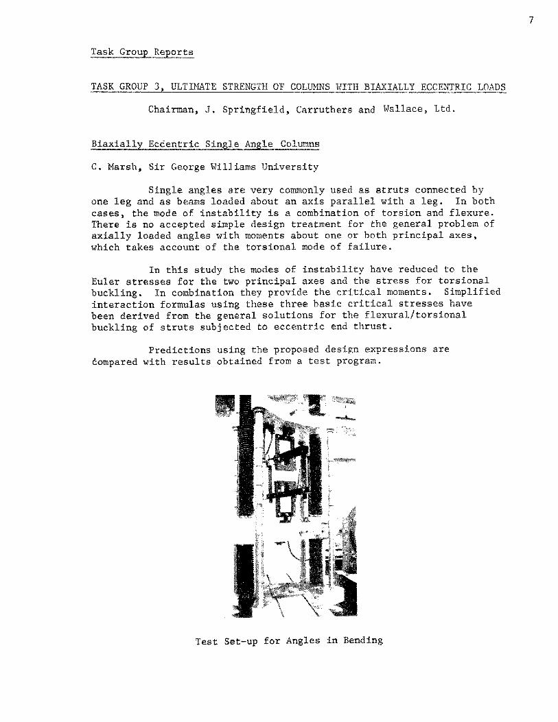
Single angles are very commonly used as struts connected by one leg and as beams loaded about an axis parallel with a leg. In both cases, the mode of instability is a combination of torsion and flexure. There is no accepted simple design treatment for the general problem of axially loaded angles with moments about one or both principal axes, which takes account of the torsional mode of failure.
In this study the modes of instability have reduced to the Euler stresses for the two principal axes and the stress for torsional buckling. In combination they provide the critical moments. Simplified interaction formulas using these three basic critical stresses have been derived from the general solutions for the flexural/torsional buckling of struts subjected to eccentric end thrust.
Predictions using the proposed design expressions are compared with results obtained from a test program.
Test Set-up for Angles in Bending
7
8
Task Group Reports
Interaction Curves For Biaxially Loaded Sections A Simplified Approach
W. F. Chen and T. Atsuta, Lehigh University
A simple method to obtain the exact interaction relationships of general sections which are composed of rectangular elements is presented. The section may be unsymmetric and the loads are a comhination of axial force and biaxial bending moments. The exactness of the solution is shown by the coincidence of the upper and lower bound solutions provided by the limit analysis. For illustrations, interaction curves for several commonly used structural steel sections are developed using the method.
Simple analytical expressions to approximate the interaction relations of wide-flange sections are proposed, and the associated plastic deformations are calculated.
y
n1 I I
--x L4x3x 3fa
I
Interaction Curves of an Angle Sect'ion
Task Group Reports
Biaxial Bending of Rectangular Tubular Columns
W. W. McVinnie and Z. Razzaq, University of Wisconsin
Test results for five biaxially loaded tubular beam columns are presented in this paper. Three of the columns had a square cross section (2 in. x 2 in. x 0.125 in.) and two were rectangular (2 in. x 1.5 in. x 0.125 in.). The columns were tested under constant ·axial load with moment applied at one end only (the "strong axis" moment was twice the "weak axis" moment). Comparison of moment-deflection curves from the tests to those obtained theoretically show good agreement, indicating, in a limited way, the theoretical solution of the biaxially loaded column is valid.
In addition, some theoretical studies are presented for columns with moments applied at each end. These results indicate that the interaction equation for biaxially loaded tubular columns proposed by Pillai and Ellis* is satisfactory.
J. 0.2 itr. ~I
T..S:eorY.J --
Test- .J
Moment Deflection Curves for Column 1.
*Pilla!, s. U., and Ellis, J. S., "Hollow Tubular Beam-Columns in Biaxial Bending", Journal of the Structural Division, ASCE, Vol. 97, No. ST5, Proc. Paper 8094, May 1971, pp. 1399-1406.
9
10
Task Group Reports
TASK GROUP 4, FRAME STABILITY AND EFFECTIVE COLUMN LENGTH
Chairman, J. S. B. Iffland, Praeger-Kavanagh-Waterbury
Studies of Effective Column Length and Frame Stability
J. H. Daniels, Lehigh University
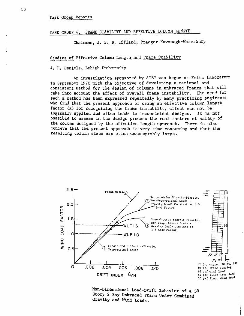
An investigation sponsored by AISI was begun at Fritz Laboratory in September 1970 with the objective of developing a rational and consistent method for the design of columns in unbraced frames that will take into account the effect of overall frame instability. The need for such a method has been expressed repeatedly by many practicing engineers who find that the present approach of using an effective column length factor (K) for recognizing the frame instability effect can not be logically applied and often leads to inconsistent designs. It is not possible to assess in the design process the real factors of safety of the column designed by the effective length approach. There is also concern that the present approach is very time consuming and that the resulting column sizes are often unacceptably large.
6--l 1-12 ft. story; 30 ft. baY 30 ft. frame spacing 20 psf wind load 75 psf floor live load 50 psf floor dead load
Non-Dimensional Load-Drift Behavior of a 30 Story 2 Bay Unbraced Frame Under Combined Gravity and Wind Loads.
Task Group Reports
Extensive theoretical studies were carried out on seven multistory (10 to 40 stories) multi-bay (1 to 5 bays) unbraced frames 5Ubjected to combined gravity and wind loads. The frames were designed using the 1969 AISC Specification provisions for allowable stress except that the effective length concept was not used, that is, K = 1.0 for all columns. Also C for braced frames was used. The frames were analyzed by computer to obt~in their first-order and second-order elastic-plastic behavior.
Preliminary observations are that all frames easily achieved a gravity load factor of 1.7 and a combined load factor of 1.3. There is an appreciable difference between the first-order and second-order loaddrift response, particularly for the taller frames, which is the result of the P~ effect included in the second-order analysis. The working load drift index for the frames consistently varied from about 0.003 to 0.004.
TASK GROUP 7, TAPERED MEMBERS
. Presiding Chairman, G. C. Lee, State University of Ne'IW York
Residual Stresses in Tapered Shapes
G. C. Lee, State University of New York
Results of experimental study on magnitude and distribution of welding residual stresses in tapered I-shapes are reported. Specimens were fabricated by an automatic welding process on only one side at the junction of web and flanges. The flange and web plate elements were cut (both shear cut and flame cut) from universal plates of 42 ksi minimum yield strength. A description of current experimental effort on the same type of fabricated specimens with rectangular web cut-outs will be given.
TASK GROUP 8, DYNAMIC INSTABILITY
Chairman, D. A. DaDeppo, University of Arizona
Response of Elastic Beams and Columns Subjected to Blast Loads
D. Krajcinovic, Argonne National Lab. and D. A. DaDeppo, Univ. of Arizona
Presented is an introduction to the problems commonly classified under the name of dynamic stability. A classification due to N. Hoff is presented and a suitable definition is given. It is underlined that most of the problems dealt with are essentially response problems as distinguished from the conventional stability problems.
ll
12
Task Group Reports
Next it is stated that two main reasons for the study of dynamic
stability are:
a) Completely different nature of the problems
b) Inadequate modeling into a corresponding static problem.
It is pointed out that the stability or instability, unlike the static i case has to be related to a selected parameter (magnitude or the durat on of the pulse, magnitude or the distribution of the initial imperfections,
etc.).
Finally, the existing literature is briefly reviewed with the emphasis on the results applicable in engineering ~esign. In addition to "exact" solution the availability of the upper bounds on the displacement is specifically outlined.
Flow-Induced Vibration of Rods and Tubes
M. W. Wambsganss, Argonne National Laboratory
Many nuclear reactor plant components can be represented as flexible rods or tubes; for example, fuel pins, heat exchanger tubes, control rods, piping, fuel assembly ducts, etc. Typically exposed to the flow of a heat-removing coolant, these components are subjected to fluid-related forces and to potential fluid/structure interactions both of which can induce and sustain vibration. The resulting motion can cause structural failure. Therefore, there exists a need for methods of analysis that can be used for design of reactor components to avoid detrimental flow-induced vibrations.
To facilitate the development of these methods, it is convenient to classify the fluid flow as parallel-flow or transverse-flow in reference to its orientation with respect to the axis of the rod or tube. This paper is concerned with parallel-flow induced vibration. The critical velocities associated with instabilities are sufficiently high that they are not expected in practice. For flow velocities below the critical velocities, ~tibrations are force-excited by random pressure fluctuations in the flowing fluid. In general, the displacement response is small, but because of the inherently small clearances and close spacings associated with many reactor components, small displacementsare critical and there exists the need for a design relationship to compute displacement response statistics.
An equation for small lateral motion of a flexible rod in axial flow is formulated. Using a phenomenological model for the convecting random pressure field, and assuming spatial homogeneity of the field, an expression for the mean-square spectral density of the displacement is derived. The results of a parameter study define ranges of parameter groupings for which, if satisfied, the spectral density function can be
Task Group Reports
integrated to yield aJ expression for mean-square displacement. The resulting relationship is in terms of rod natural frequency, damping factor, and intensity of the mean-square pressure spectrum in the lowfrequency range; all three are functions of mean axial flow velocity. Empirical expressions are developed for damping factor and intensity of the pressure spectrum. With these, an empirical equation for rms displacement is written which is in terms of known quantities and, therefore, provides a tool which can be used by designers.
Dynamic Response of Columns Under Short Duration Axial Loads
I. K. Mcivor, University of Michigan
This study examines the lateral response of columns subject to axial impact loading. In contrast to most previous investigations, it includes the effect of axial inertia. When axial inertia is neglected, the axial force is accounted for only during the duration of the loading. In fact, the column is in a state of free axial oscillation after the load is removed. Even in the presence of damping, this may lead to significantly larger lateral motions than predicted if axial inertia is neglected.
Since the nature of the axial oscillation is crucial to the analysis, a realistic model must include internal damping. In the present study material dissipation is included by employing a Kelvin-Voight model for the material behavior. Equations of motion in which the axial and transverse motions are coupled through geometric nonlinearities are derived. The dynamic response is then obtained by numerical integration.
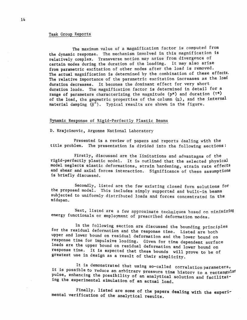
The maximum value of a magnification factor is computed from the dynamic response. The mechanism involved in this magnification is relatively complex. Transverse motion may arise from divergence of certain modes during the duration of the loading. It may also arise from parametric excitation of other modes after the load is removed. The actual magnification is determined by the combination of these effects. The relative importance of the parametric excitation increases as the load duration decreases. It becomes the dominant effect for very short duration loads. The magnification factor is determined in detail for*a range of parameters characterizing the magnitude (p*) and duration (T ) of the load, the ge~metric properties of the column (a), and the internal material damping (S ). Typical results are shown in the figure.
Dynamic Response of Rigid-Perfectly Plastic Beams
D. Krajcinovic, Argonne National Laboratory
Presented is a review of papers and reports dealing with the title problem. The presentation is divided into the following sections:
Firstly, discussed are the limitations and advantages of the rigid-perfectly plastic model. It is outlined that the selected physical model neglects elastic deformations, strain hardening, strain rate effects and shear and axial forces interaction. Significance of these assumptions is briefly discussed.
Secondly, listed are the few existing closed form solutions for the proposed model. This includes simply supported and built-in beams subjected to uniformly distributed loads and forces concentrated in the midspan.
Next, listed are a few approximate techniques based on minimizing energy functionals or employment of prescribed deformation modes.
In the following section are discussed the bounding principles for the residual deformation and the response time. Listed are both upper and lower bound on residual deformation and the lower bound on response time for impulsive loading. Given for time dependent surface loads are the upper bound on residual deformation and lower bound on response time. It is expected that these bounds will prove to be of greatest use in design as a result of their simplicity.
It is demonstrated that using so-called correlationparameters, it is possible to reduce an arbitrary pressure time historv to a rectan~ula! pulse, enhancing the possibility of an analytical solution and facilitating the experimental simulation of an actual load.
Finally. listed are some of the papers dealing with the experimental verification of the analytical results.
Task Group Reports
Dynamic Parametric Instability and Response of Frameworks
F. Y. Cheng and W. H. Tseng, University of Missouri -Rolla
This presentation describes the analytical behavior of instability and response of frameworks subjected to transverse dynamic excitations such as harmonic forces, impulses, or earthquakes and longitudinal pulsating forces composed of static and harmonic forces. The longitudinal frequency Q is different from the natural frequency w of the system.
Figure a shows the instability region described by a, S, and w of a step member subjected to longitudinal force Ft = aP + SP cosQt where the static buckling load P
0 and the natural frgquenc~ ware
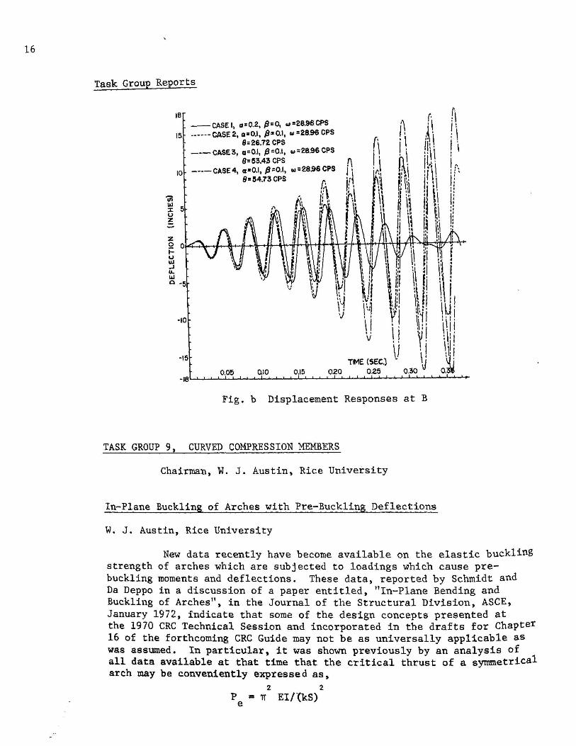
determined as 2975 kips and 28.95 cps, respectively· When a lateral force P • 30 coswt (kips) is applied at B, the elastic dynamic displac~ments at B for four different longitudinal frequencies Q's, are shown in Fig. b in which Cases 3 and 4 are in the dynamic instability region. Note that the amplitudes of lateral vibrations corresponding to Cases 3 and 4 grow exponentially. Other examples of multistory frames presented have the similar behavior.
Dynamic behavior of inelastic systems has been presented for a ; 0 and ~ = 0 with lateral forces of transient loads and earthquakes as well as viscous damping expressed in modal matrix and in linear combination of mass and stiffness matrices.
In-Plane Buckling of Arches with Pre-Buckling Deflections
W. J. Austin, Rice University
I~J . .. . I 'I" \.11 :\: i 1·1· ~~I 0.~
New data recently have become available on the elastic buckling strength of arches which are subjected to loadings which cause prebuckling moments and deflections. These data, reported by Schmidt and Da Deppe in a discussion of a paper entitled, "In-Plane Bending and Buckling of Arches", in the Journal of the Structural Division, ASCE, January 1972, indicate that some of the design concepts presented at the 1970 CRC Technical Session and incorporated in the drafts for Chapter 16 of the forthcoming CRC Guide may not be as universally applicable as was assumed. In particular, it was shown previously by an analysis of all data available at that time that the critical thrust of a symmetrical arch may be conveniently expressed as,
2 2.
P = iT EI/{kS) e
17
Task Group Reports
in which Pe is the axial compression at the quarter points of the span, S is one-half the length of the arch axis, and k is an effective length factor. The value of k was shown to be approximately equal to that for a "corresponding" column and this value was found to be insensitive to both the shape of the arch axis and the type of loading. These conclusions now appear to be overly optimistic on the basis of the following new solutions.
(1) New solutions for two-hinged circular arches subjected to dead load indicate that the values of k for large risespan ratios are much greater than the corresponding values for the same arches subjected to either normal loading or to a concentrated load at the crown.
(2) New solutions for fixed circular arches with a concentrated load at the crown indicate that the buckling mode is different than was found before for normal loading and the k values are greater.
It is now apparent that the type of loading does significantly affect the critical value of P in the equation above and the mode of failure. The simple formula citea above may not be as useful in simplifying the design procedure as was thought. More information is necessary before a simple, reliable and widely applicable design procedure can be developed.
Load-Carrying Capacity of Arches Considering the Effects of Spread of Yielding and Finite Deformation
s. Kuranishi, Tohoka University and Le-Wu Lu, Lehigh University
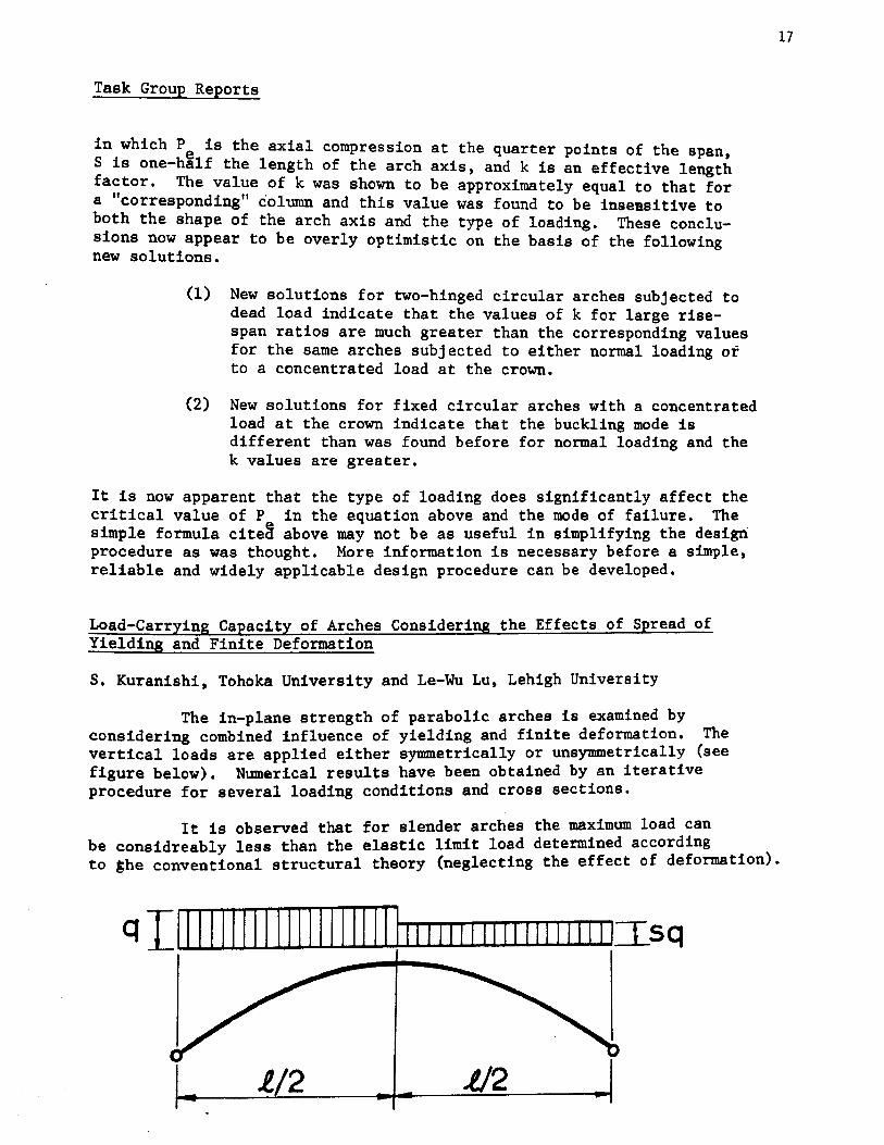
The in-plane strength of parabolic arches is examined by considering combined influence of yielding and finite deformation. The vertical loads are applied either symmetrically or unsymmetrically (see figure below). Numerical results have been obtained by an iterative procedure for several loading conditions and cross sections.
It is observed that for slender arches the maximum load can be considreably less than the elastic limit load determined according to ~he conventional structural theory (neglecting the effect of deformation).
q Illlllllllllllllllllll1111111111111111111 [I_sq
l./2 J./2
18
Task Group Reports
TASK GROUP 10, DESIGN OF LATERALLY UNSUPPORTED BEAM COLUMNS
Chairman, T. V. Galambos, Washington University
Moment-Curvature Characteristics for Inelastic Beam-Columns
C. K. Yu, Missouri Highway Department
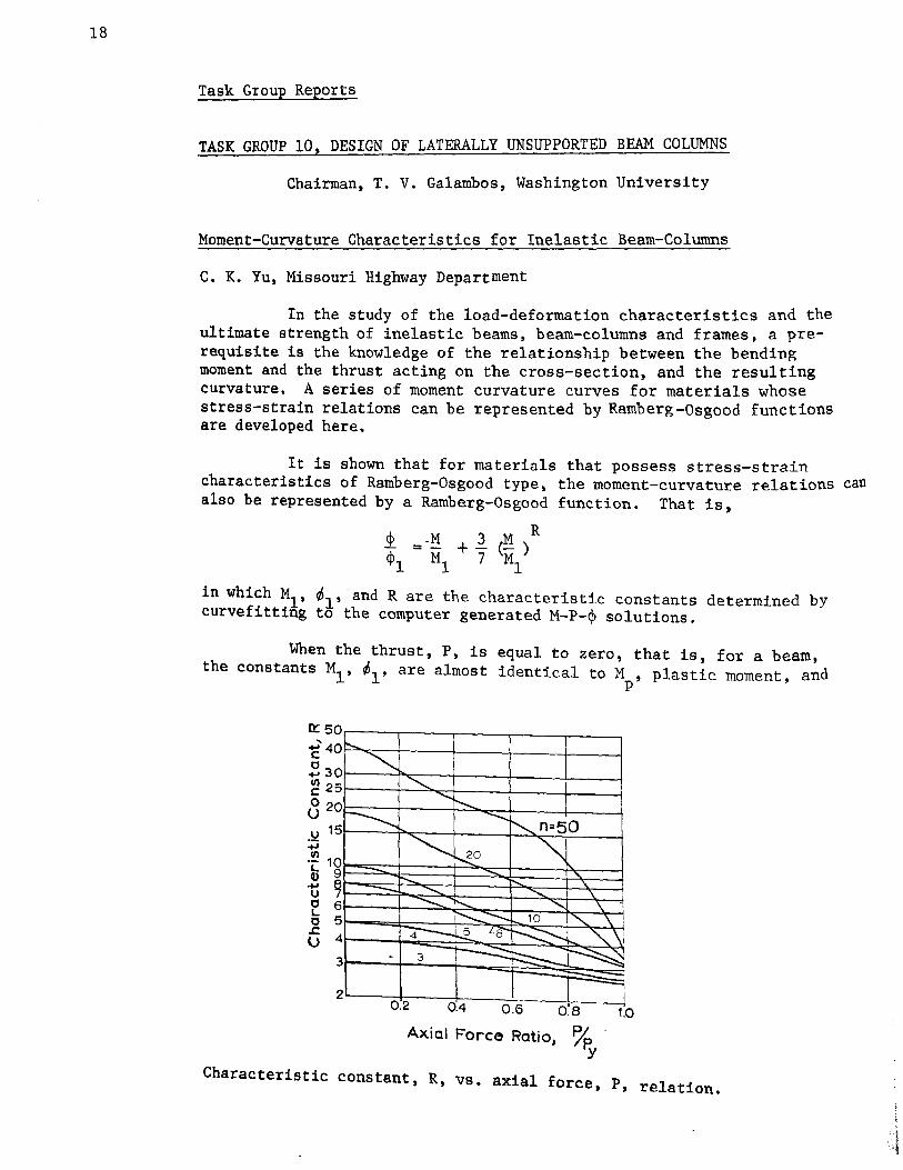
In the study of the load-deformation characteristics and the ultimate strength of inelastic beams, beam-columns and frames, a prerequisite is the knowledge of the relationship between the bending moment and the thrust acting on the cross-section, and the resulting curvature. A series of moment curvature curves for materials whose stress-strain relations can be represented by Ramberg-Osgood functions are developed here.
It is shown that for materials that possess stress-strain characteristics of Ramberg-Osgood type, the moment-curvature relations can also be represented by a Ramberg-Osgood function. That is,
R 1 = ·!i + l_ (M ) ¢1 Ml 7 Ml
in which M1, ~l' and R are the characteristic constants determined by curvefitting to the computer generated M-P-¢ solutions.
When the thrust, P, is equal to zero, that is, for a beam, the constants M1 , ~l' are almost identical to M , plastic moment, and
p
Axial Force Ratio, % · y
Characteristic constant, R, vs. axial force p , , relation.
Task Group Reports
M
~p (• Ef), respectively, and R, equal ton, the exponential parameter for
the stress-strain curve. In other words, moment curvature relation for the beams assumes a shape the same as that for its stress-strain curve and can be expressed as,
L = M + l (~)n ~p Mp 7 Mp
However, for beam-column members (P + 0), M1
, ¢1
and R must be determined from prepared charts and they are not the same values as shown for beams.
Interaction Equations for Beam-Columns, A Critique
J. A. Yura, University of Texas
Interactions equations are derived for metal beam-columns. Emphasis is placed on beam-columns in which the elastic limit is exceeded under axial load alone (cr > 0. 5 cr ) , those in which sidesway . is permitted, and beam-columns in §fories wi~h columns of varying buckling characteristics. It is shown that two reasonably simple interaction equations can be used to handle all cases. Comparisons are made with existing solutions and test results. One of the results of the theoretical study shows that C • 1.0 should be used for sidesway permitted cases. The use of C = 0.85 f~r sidesway permitted cases is unconservative for most practicai cases in multi-story frames.
19
20
R
Task Group Reports
Experiments on Laterally Loaded Steel Wide-Flange Beam-Columns
G. W. English and P. F. Adams, University of Alberta
A procedure for designing laterally loaded steel beam-columns based on the use of interaction equations is proposed. An experimental program was performed on such members; the test setup, procedure, and results were presented. The experimental results indicate that the design proposal is accurate and slightly conservative.
10
8 13 14
8 9 1011 12
6 ~ (kips)
B.C.- 5 4 18
~ P/Py=0.53
l/rx=78
2 p
0 20 19
0 2 3 4 5 6 b,. (inches)
Load-Deflection Relationship _ BC-S
Task Group Reports
TASK GROUP 11, EUROPEAN COLUMN STUDIES
Chairman, D. Sfintesco, C.T.I.C.M.
European Column Tests
N. Tebedge, W. F. Chen, and L. Tall, Lehigh University
In order to obtain conclusive experimental evidence on the strength of heavy columns with minimum cost, the program is restricted to testing specimens from four countries: Belgium, Britain, Germany and Italy. The test program consists of column tests (slenderness ratio of 50 and 95) and supplementary tests, namely, tension tests (full-size and ASTM standard), residual stress measurements, and stub column tests.
The column tests as well as the supplementary tests have
21
been completed. The column test results are compared in the figure with the latest proposed European Convention Column Curve (B3-37). A good correlation for L/r = 95 and slightly unconservative prediction for L/r = 50 are observed.
ksi kp/cm 2
CRITICAL STRESS
20
10
0
1000
0
6 Belgium
• Brita in • Germany
o Italy
40 80 SLENDERNESS RATIO
Column Strength Curve
European Convention Curve
160 200
Comparison of Column Test Results (HEM 340) with Proposed ECCS and CRC Column Strength Curve.
22
Task Group Reports
TASK GROUP 13, THIN WALLED METAL CONSTRUCTION
Chairman, S. J. Errera, Bethlehem Steel Corporation
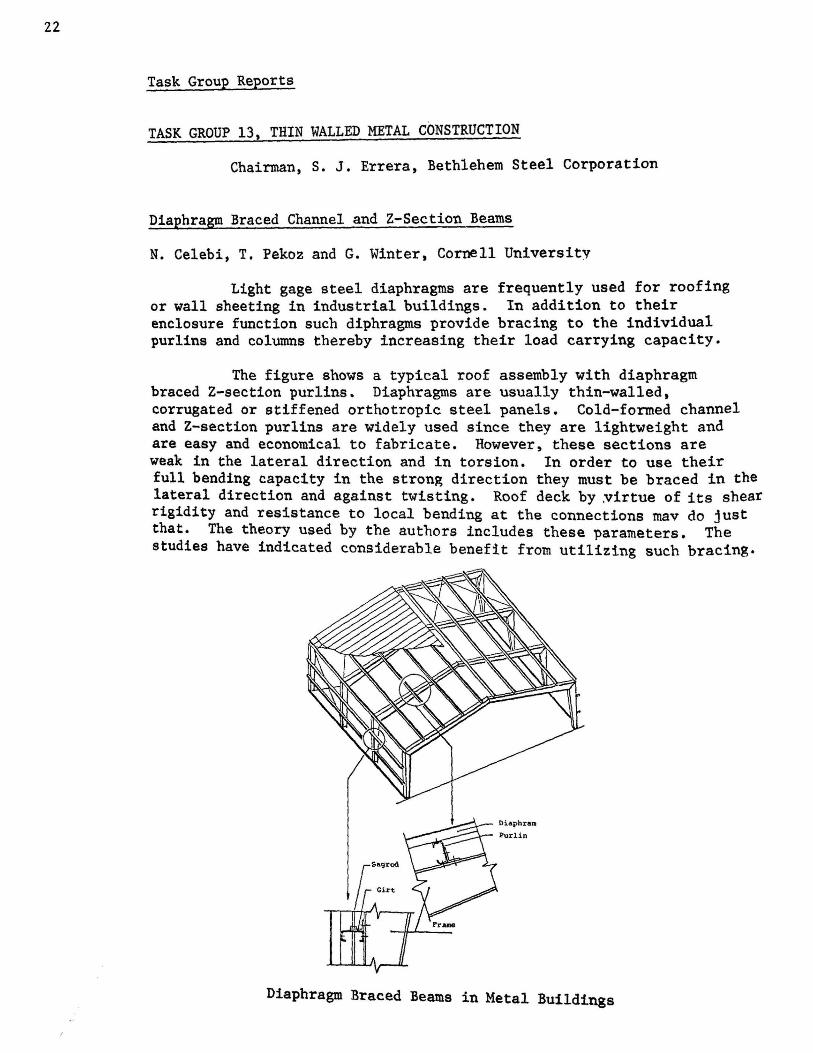
Diaphragm Braced Channel and Z-Section Beams
N. Celebi, T. Pekoz and G. Winter, Cornell University
Light gage steel diaphragms are frequently used for roofing or wall sheeting in industrial buildings. In addition to their enclosure function such diphragms provide bracing to the individual purlins and columns thereby increasing their load carrying capacity.
The figure shows a typical roof assembly with diaphragm braced Z-section purlins. Diaphragms are usually thin-walled, corrugated or stiffened orthotropic steel panels. Cold-formed channel and Z-section purlins are widely used since they are lightweight and are easy and economical to fabricate. However, these sections are weak in the lateral direction and in torsion. In order to use their full bending capacity in the strong direction they must be braced in the lateral direction and against twisting. Roof deck by ~irtue of its shear rigidity and resistance to local bending at the connections mav do just that. The theory used by the authors includes these parameters. The studies have indicated considerable benefit from utilizing such bracing.
Diaphragm Braced Beams in Metal Buildings
Task Group Reports
Results of a limited number of tests are in reasonable agreement with the analytical results.
This research reported was sponsored by American Iron and Steel Institute.
Interaction of Postcritical Plate Buckling and Overall Column Buckling of Thin-Walled Members
J. DeWolf, T. Pekoz, and G. Winter, Cornell University
This investigation has been aimed at developing information on the interaction between postcritical plate buckling and overall column buckling. Thirty-three columns were tested. Both the postcritical plate buckling strength and the overall column buckling strength were varied systematically.
Two types of column sections were tested; they are shown in the illustration. The tubular section was used to study the behavior of component plates joined at both edges by other plate elements, and the "H" section was used to study the behavior of component plates joined on one edge by another plate element and free at the other edge.
The experimental carrying capacity has been compared with the expected strength when (1) local instability is entirely neglected; (2) the effect of local instability is based on the critical bifurcation stress, neglecting any postcritical strength; (3) postcritical buckling is included approximately by means of an effective width concept.
On the basis of the test results and theoretical comparisons, it has been shown that (1) the strength of thin-walled columns can be considerably reduced by local plate buckling; (2) column capacities calculated on the basis of the classical critical plate buckling stress considerably underestimate the actual column strength; (3) the effect of the postcritical strength of the component plates increases the column strength significantly over that determined by the critical plate buckling stress; (4) a method based on the postcritical effective widths of the component plates promised to furnish a satisfactory tool for calculating the strength of thin-walled columns.
""l:::==========:J Interaction of Postcritical Plate Buckling
23
24
Task Group Reports
Chairman~ R. L. Haenel, Larsen & Ludwig
TASK GROUP 16, PLATE AND BOX GIRDERS
Chairman, F. D. Sears, Department of Transportation
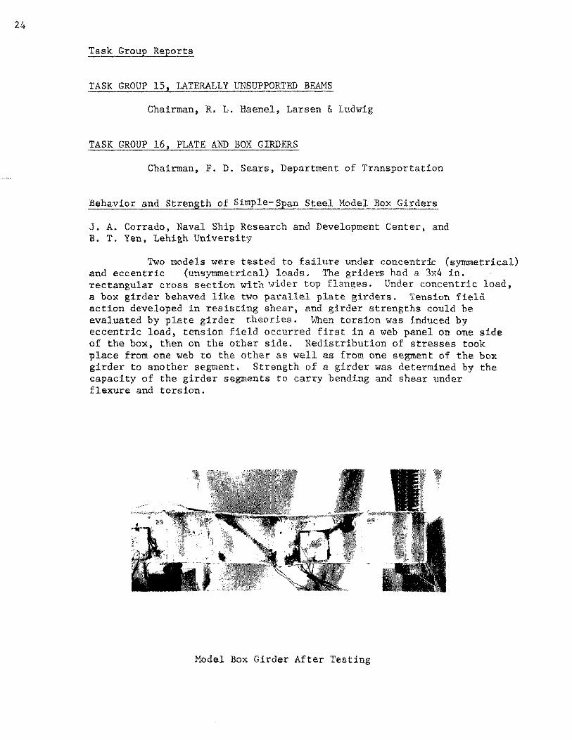
J. A. Corrado, Naval Ship Research and Development Center, and B. T. Yen, Lehigh University
Two models were under concentric (symmetrical) and eccentric (unsymmetrical) griders had a 3x4 in. rectangular cross section with Under concentric load, a box girder behaved two girders. Tension field action developed in resisting strengths could be evaluated by plate girder torsion was induced by eccentric load, tension occurred in a web panel on one side of the box, then on the other side. Redistribution of stresses took place from one web to the other as well as from one segment of the box girder to another segment. Strength a was determined by the capacity the girder segments to carry bending and shear under flexure and torsion.
Model Box Girder After Tes
Task Group Reports
TASK GROUP 17, STABILITY OF SHELL-LIKE STRUCTURES
Chairman, K. P. Buchert, University of Missouri
The Stability of Shell-Like Structures l~ith Negative Gaussian Curvature
K. P. Buchert, University of Missouri
The equations that may be used to calculate the buckling load of a hyperbolic parabolid shell-like structure are given. The buckling equations for spherical segments, cylinders and H.Ps. are compared and ~n approximate method is proposed for calculating the buckling stress of a hyperbolic cooling tower. The results were applied to a reinforced concrete tower and indicate that stability problems may have contributed to the failure of reiforced concrete towers.
TASK GROUP 18, TUBULAR MEMBERS
Chairman, A. L. Johnson, American Iron and Steel Institute
Current Activities in Tubular Members
D. R. Sherman, University of Wisconsin
There is considerable effort presently being put forth to translate the analytical and experimental knowledge concerning the behavior of tubes into design oriented specifications and guides. In order to understand the complexity of this task, it must be realized that several distinct types of tubes exist. Tubes can be classified as manufactured products (either hot or cold formed), fabricated, or stiffened shells. Organizations working on various aspects of tubular design criteria include:
1. CRC Task Group 18 - Stability of all types of round tubes
2. AISI - General design specifications for manufactured round and rectangular tubes
3. ASCE - General design specification for fabricated and manufactured tubes
4. CIDECT - European program primarily for hot formed manufactured tubes and connections of rectangular tubes
5. AWS - Connections of round tubes
Tubes subjected to axial compression can buckle either as columns or locally in the wall. Column buckling is effected by residual stresses and straightness just as for other shapes. However, local buckling is
25
26
Task Group Reports
extremely sensitive to initial imperfection in the wall or roundness and failure can occur at loads much lower than predicted by classical theory. Although local buckling is discussed extensively in the literature, much of the information comes from the aircraft industry and does not apply to the tolerances and heavier walls encountered in civil engineering structures.
Although tubes have a favorable shape factor for bending, there is some question as to whether moment redistribution will be prevented by insufficient rotational capacity due to ovalization. The D/t limit between compact sections suitable for plastic design and semi-compact sections which will develop plastic moments but will not redistribute the moment requires definition. Also, the limit between the semi-compact section and one which fails by inelastic local buckling is not known.
When writing interaction equations, it is necessary to consider torsion as well as axial load and bending. In addition, due to the enclosed nature of a tube, pressures can develop which may effect the primary load carrying capacities. Consequently, although design specifications are being written to reflect the difference in behavior between tubes and other shapes, there are still several questions requiring better answers.
-A Proposed Column Curves
for Rot and Cold Formed Tubes
Task Group Reports
CIDECT Research on Tubular Members
S. Stadnyckyj, The Steel Company of Canada, Limited
C.I.D.E.C.T. is "The International Committee for the Study and Development of Tubular Structures". This is an organization of companies, both European and North American, which manufacture tubular products. The North American members are U. S. Steel and The Steel Company of Canada, Limited. Current CIDECT programs emphasize square and rectangular members, as these are proving to be the most popular sections for structural use. The results of a few of these research programs as described below:
"'0 u .._.. z w u LL. LL. w 0 u (.!) <t a: Q
Air Flow
1.
Air Flow
Plastic Behavior of Tubular Members - Shape factors of square and rectangular sections vary between 1.16 and 1.43, depending on the b/t ratio. The shape factor of rounds varies from 1.29 to 1.43. Depending on the width to thickness ratio, tubular members can be classified as reduced stress, non-compact, compact, or plastic design sections. Using these shape factors, it is seen that the allowable tension stress, in bending, of a tubular member should be between 70 and 80 percent of the yield stress.
WF
Square HSS
B"x 4"
----------.. HSS- 12"x 4"
HSS -IO"x 6"
a
105
REYNOLDS NO. , Re
Effect of Corner Radius
~ =0.05
0.05
0.12 --~··nd \1~----R~-· -·
0.20
Normal Range of Reynolds No.
lo6
27
28
Task Group Reports
2. CIDECT research on wind loads suggests that rectangular sections have drag coefficients bwer than those of square and wide flange sections. (See Figure.) The drag coefficients is significantly affected by the size of corner radius of a tubular member. Round tubular members offer the best section for wind loading. This CIDECT data has been used for the design of the Bell Transmission Tower in Toronto, and contributed to the increased use of rectangular members in ventilated mine shafts.
3. CIDECT has issued European design manuals for the design of eccentrically-loaded tubular columns. U. s. Steel and The Steel Company of Canada are preparing a North American version to be published in 1972.
4. Based on an e~tensive series of CIDECT-sponsored joint tests, design rules have been developed for tubular joints with square and rectangular members. The Steel Company of Canada has issued a design manual for tubular connections derived from this research.
TASK GROUP 19, STIFFENED PLATE STRUCTURES
Chairman, R. G. Kline, United States Steel Corporation
TASK GROUP 20, COMPOSITE MEMBERS
Chairman, S. H. Iyengar, Skidmore, Owings & Merrill
C 0 N T R I B U T I 0 N S 0 F T A S K R E P 0 R T E R S
TASK REPORTER 11, STABILITY OF ALUMINUM STRUCTURAL MEMBERS
J. W. Clark, Aluminum Company of America
Recent Work on Buckling of Welded Aluminum Structures
J. W. Clark, Aluminum Company of America
The heat of welding reduces the strength of heat-treated or cold-worked aluminum alloys in the heat affected zone surrounding the weld. This presents problems in designing welded aluminum structures to resist buckling. Either the entire design must be based on the relatively low strength of the heat affected material or special account must be taken of the effect of the welding on structural stability. Specifications for aluminum structures have taken the latter route (1).
Methods proposed for predicting the strength of welded aluminum tubes for design purposes were supported by the results of tests on tubes from 4.5 to 8 in. in diameter (2). These methods are further confirmed by recent tests of circumferentially welded tubes up to 11 in. in diameter. The specimens included simple butt welds, butt welds with integral backup, and joints with one end of the tube expanded to fit over the end of the adjacent tube.
b. 2
L Lh -a-+ r r 1T
2 L 0 r
(1)
(2)
Columns With Part of Length Affected by Heat of Welding
Aluminum Construction Manual, Section 1, Specifications for Aluminum Structures, The Aluminum Association, 1971.
"Design of A1 uminum Tubular Members", by J. W. Clark and R • L • Rolf • Journal of the Structural Division, Proceedings, ASCE, December, 1964
p. 259.
29
30
It has been demonstrated that overall column buckling strength of welded aluminum members with transverse butt welds can be predicted by considering the member as a stepped column, where the step is in the stress-strain characteristics rather than the moment of inertia of the cross section (3). However, the resulting design procedures are quite tedious. A simplified design procedure has been reveloped, in which the actual length of the column is replaced by an increased length that depends on the portion of the total length that is affected by the heat of welding. The procedure is derived by considering a column with equally spaced welds distributed along its length. The illustration shows equations applicable to columns with a single weld at the center and with N equally spaced welds. The equations relate the slenderness ratio for the column (L/r) to those for an all heat-affected column (L /r) and an all parent metal column (L /r) that would fail at the same st~ess as the
0 actual column. Design formulas derived from these equations are included in current specifications (1).
(3) "Strength of Welded Aluminum Columns", by R. J. Brungraber and J. W. Clark, Transactions, ASCE, Vol. 127, Part II, 1962, p. 202.
R E S E A R C H R E P
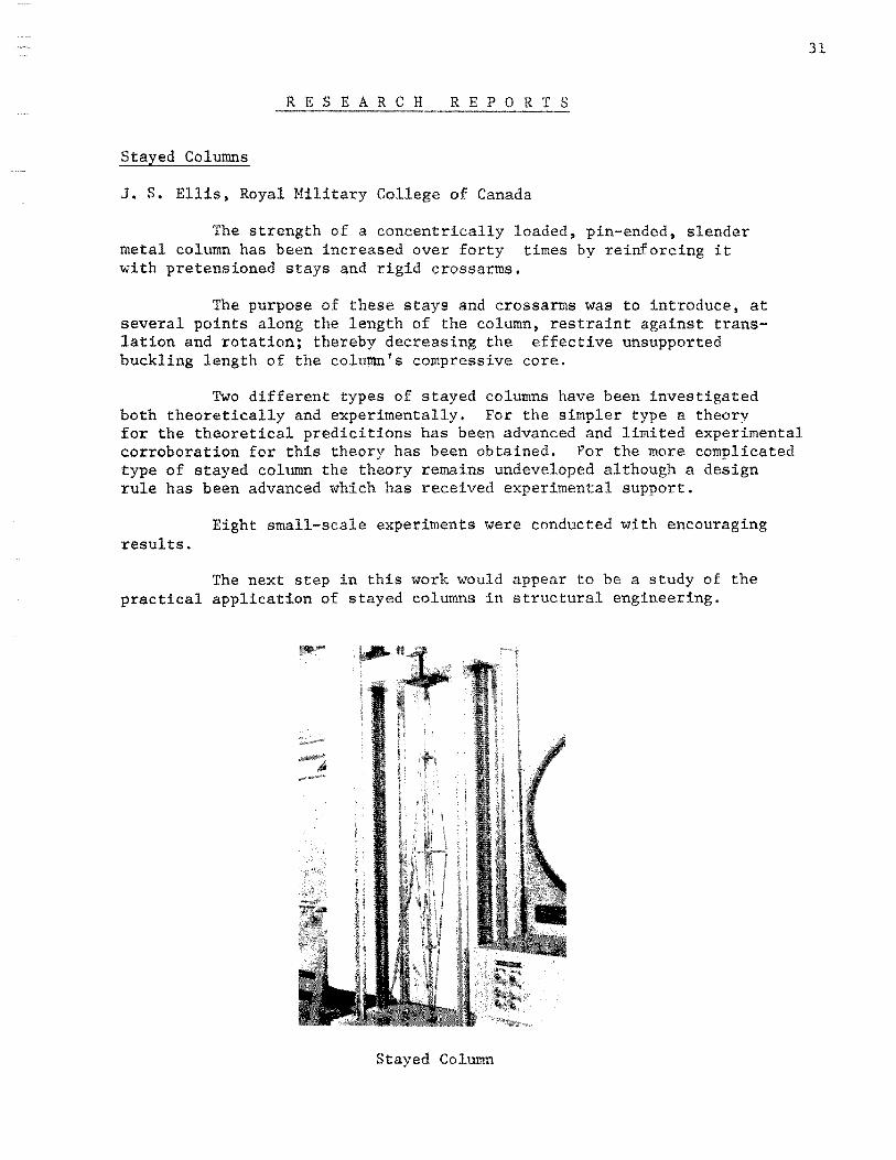
J. S. Ellis, Royal Military College of Canada
The strength a concentrically loaded, pin-ended, slender metal column has been increased over forty times by reinforcing it with pretensioned stays and rigid crossarms.
The purpose of these stays and crossarms was to introduce, at several points along the length of the column, restraint against translation and rotation; thereby decreasing the effective unsupported buckling length of the column's compressive core.
Two different types of stayed columns have been investigated both theoretically and experimentally. For the simpler type a theory for the theoretical predicitions has been advanced and limited experimental corroboration for this theory has been obtained. For the more complicated type of stayed column the theory remains undeveloped although a design rule has been advanced which has received experimental support.
Eight small-scale experiments were conducted with encouraging results.
The next step in this work would appear to be a study of the practical application of stayed columns in structural engineering.
Stayed Column
31
32 Research Reports Continued
Bridging Spacing for Longspan Steel Joists
J. M. Leigh, Washington University
Longspan steel joists used as flexural members in completed structures, are laterally restrained by either the decking or the' concrete slab which they support. During construction, joists are unsupported laterally and must be bridged in order to prevent weak axis buckling due to loads imposed by construction workers. The magnitude of these loads cannot be precisely defined; however, sine~ elastic buckling is a function only of the joist geometry and ~he intervals along its length at which lateral bracing applie~ itis possible to define a.relationship which predicts the bridging spacing at which joists will be fully restrained from elastic instability.
This study constituted an experimental investigation wherein a total of 30 tests were performed on joists of varying load capacity and web member arrangement. Two equal concentrated loads were applied at locations equi-distant from the joist ends thus producing a uniform moment ori the joist between the two load points. The buckling load for each joist was determined and the buckling stress in the top chord was computed using the beam flexural formula. These results compared extremely well with the theoretical Euler column formula;
F cr = 7T2 E
(K L/r) 2
where the effective length factor, K, depends on the bridging spacing and the assignment of axial load to the joist top chord.
It was concluded that the Euler column formula is a satisfactory basis for estimating the bridging spacing at which joists will be fully restrained from elastic buckling.
·;;; -"'
' ..._t;
' ~ (f) IJJ 0: 1-~
0 0: 0 I u CL 0 1-
15
Legend
o One Sided Web
o Standard Web
A Alter note Web
0 50 100 I 50 200 250
TOP CHORD SLENDERNESS RATIO- Krl
15 ft. & 20 ft. Bridging Test Results
Compared to the Euler Column Curve
C R C G U I D E R E P 0 R T
COMMITTEE ON THE CRC GUIDE
Chairman, E. H. Gaylord, University of Illinois
Progress Report on the Third Edition
B. G. Johnston, Editor; University of Arizona
Thanks to the cooperation of all of the task groups concerned with the guide, drafts of all of the chapters are either finished, or nearly finished.
The first "package" of edited chapters, in final or nearly final form, was mailed out to the Executive Committee and concerned task groups -- and others -- on March 15, 1972. This covered Chapters 1, 2, and 3. Other chapter groups will be mailed out in succeeding weeks with final mailing in early fall. It now seems definitely feasible to get the complete manuscript to the publisher in late 1972 which should permit publication in late 1973.
Professor Richard W. Furlong has volunteered to prepare an additional chapter on Composite Columns. If this is received by the summer of 1972 it will expand the third edition to nineteen chapters in all.
33
34
Panelists Asrow, Robertson &
Moderator, Fazlur Khan
PANEL D I S C U S S I 0 N
STABILITY PROBLEMS OF NOVEL BUILDING SYSTEMS
MODERATOR: F. R. Khan, Skidmore, Owings & Merrill
PANEL SPEAKERS :
S. P. Asrow, C. F. Murphy Associates L. E. Robertson, Skilling, Helle, Christiansen & Robertson S. H. Iyengar, Skidmore, Owings & Merrill
PROF. GALAMBOS
I am Ted Galambos, currently Chairman of the Column Research Council, and ~·ould like to welcome you to this evening panel session which has as its purpose to confront, so to speak, the researchers working on problems of instability with the people who are using the information and who will show us what they would like to know about the problems that they are supposed to be solving. So for that purpose we have assembled here a rather distinguished panel of gentlemen. I want to again welcome you and turn over everything to the able leadership of Fazlur Khan, who will moderate the panel discussion.
DR. KHAN
Thank you. I think we are going to have a very interesting session. The title "Stability Problems of Novel Building Systems" means we're really going to go all the way into systems that are out of the traditional. On the question of stability, I am sure we will hear something very interesting beyond the normal column stability and hopefully go into the entire building stability as a total problem.
We have three speakers who will give their 20 minute plus/minus talks.
Our first speaker is Sherwin P. Asrow. He is the Chief Structural Engineer of c. F. ~urphy Associates, who have done some very excellent and very significant buildings, and as such he is eminently qualified to talk about some of these special problems.
35
36
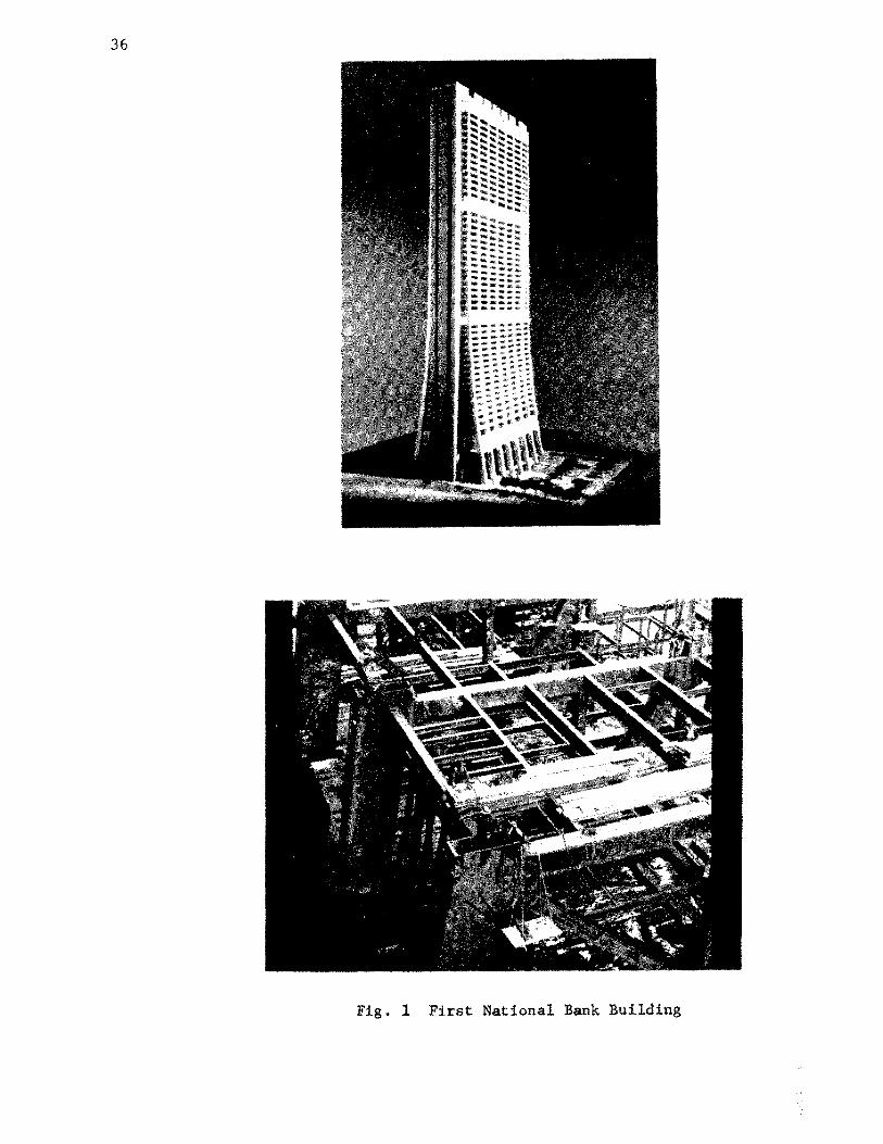
Fig. 1 First National Bank Building
/
Panel Discussion
MR. ASROW
The structure I will present for discussion I'm not sure can be considered a novel building system, but I discussed this with Ted Galambos and he felt that it would be. You can judge for yourself whether it's novel or not; it is the First National Bank Building (Fig. 1) in Chicago that C. F. Murphy Associates designed in joint venture with the Perkins and Will Partnership. It's located in the heart of downtown. The building has 60 stories with 4 basements. It tapers from a base of about 200 feet to a top dimension of 96 feet. The structure is 320 feet in the east-west dimension and the elevator cores are located at each end. The cooling towers are at the top level and a typical floor has the elevators at each end. The mezzanine level, i.e., the second floor, does not extend all the way out to the north and south lines of the building. The trusses at the 3rd floor level transfers the more closely-spaced columns above, to a 90 foot span column spacing at the 1st floor level. The basic direction of the beams is east-west. The columns in the east-west direction, that is the major columns, are at 40 feet on center and in the other direction approximately 50 feet on center, that is, above the 3rd floor.
The lateral bracing system in the north-south direction consists of a set of welded beams in vierendeel action; a truss between the 40th floor and the 42nd floor, a truss between the 23rd floor and the 25th floor, and the truss between the 3rd and the 5th floors. In the east-west direction, the system is basically vierendeel bracing above the 42nd floor, and below the 42nd floor, sets of X-braces; these are in back of the elevator cores. These heavy X-braces here are linked to the interior vierendeel system with simple connection beams because the column li.nes do not line up. Below the 8th floor is an encasement fer the steel X-brace members which form concrete shear
'walls having bar reinforcing steel as its main strength. The X-bra.cing is there primarily for construction purposes.
The major exterior columns are 2'-10" by 8'-0" at grade and this reduces with height. The bracing horizontal members are relatively small, (Fig. 2). The box member whi.ch is 2'-10" by 8'-0" at the bottom, has the side plates about 2" thick and the flange plates about 4" thick.
The structure was analyzed using a FRAN computer program in an IBM 7094. The lateral forces were distributed to the north-south bents in accordance with their stiffness so as to give approximate equal deflections at all floors. This was a difficult problem. We just didn't have the capabilities to handle the entire building at one time. Then, by linking the end cores to the interior, as I mentioned before, we were able to accomplish an east-west analysis on the building as a total entity. In other words, we did not break it into bents in the east-west direction. We made an approximate analysis of the building to arrive at the member sections we used for the
37
38
Panel Discussion
Mr. As row, Cont' d
computer analysis in a very crude way. In this rather crude analysis we made an assumption of a column length equal to 1-1/2 times the actual length above the 7th floor; that was in both directions. Below the 7th floor, we used a K-factor of 1.0. The columns are braced by shallow light plate girders in the north-south direction. At the time that we did this, it was clear that the method given in the AISC Commentary would require much greater K-factors in order to assure stability. Since the columns were so large, the G-values at the top and bottom of the columns would be greater than 20.
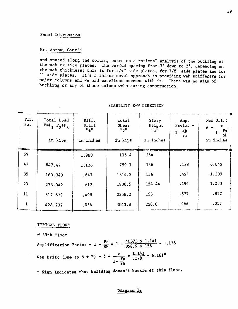
After the first computer runs were completed, we found that the drifts due to lateral forces were less than 1 in 500, either on a story-by-story basis or from any floor to the top of the building. We consulted with Professor John Goldberg of Purdue University, to arrive at an approximate general stability analysis for the building. This method permitted a stability analysis on a story-by-story basis (Diagram 1). In the diagram, "e" is the drift in a particular story height and S is the shear force or wind producing that deflection, then the lateral shear stiffness of the story is shear over deflection. When the axial loads are taken into account in this method, the true drift will be some amount, c, greater than "e". If we consider the shear and the axial load both acting, then the teal shear is equal to S + (P x 8 over h) as we see. Since the resisting shear is equal to the shear stiffness times the correct drift, we have what is shown on this diagram, and solving for 8, we obtain e over 1 minus Pe over Sh. This gives an approximate, but more realistic, figure for the drift; but even more important, as long as the denominator does not go less than zero the building will not buckle. In order to apply these principles an assumption was made as to the realistic loads that would exist at the time buckling could occur and a factor of safely of 1.7 was applied to them. Also with this factored realistic load, the drift "e" due to wind was re-computed using column properties modified to allow for
axial stress; that is, an I-value equal to the actual I x l-Column Load Euler Column Ld '
was used to obtain the results shown on this diagram. You will note that the amplification factor in the north-south direction were all close to 1, and in the east-west direction were varied. Logically, where the vierendeel only occurs, for example above the 42nd floor, the drift increases 6 times. However, the amplification factor was never negative, and, therefore, buckling would not occur.
One more problem that should be mentioned. The columns are quite large and to develop the standard type of diaphram for this large column to stiffen the webs would add material, welding and so forth. We used 6" x 6" x 3/p;: thick square tubes as diaphrams. These were welded at each end to the webs
Flr. No.
59
47
35
23
11
1
Panel Discussion
Mr. Asrow, Conr'd
and spaced along th~ column, based on a rational analysis of the buckling of the web or side plates. The varied spacing from 3' down to 21 , depending on the web thickness; this is for 3/4" side plates, for 7/8" side plates and for 1" side plates. It's a rather novel approach to providing web stiffeners for major columns and we had excellent success with it. There was no sign of buckling or any of these column webs during construction.
STABILITY E-W DIRECTION
---· r--------- -- --'
----------- ____ , ----------··· ----·
Total Load I Diff. I Total Story Height "h II
1 Amp. New Drift P=P1+P2+P
3 i Drift I "e"
in kips in inches
1.980
847.47 1.136
160.343 .647
233.042 .612
317.639 .498
428.732 .056
TYPICAL FLOOR
@ 55th Floor
Shear "S"
in kips
-115.4
759.1
1314.2
1830.5
2358.2
3043.8 ------
i n inches
264
156
156
154.44
156
228.0
Factor •
1_ Pe
Sh
.188
.494
.496
.571
.966 ----------
Pe 40375 X 1.141 • +. 178 Amplification Factor • 1 - Sh • 1 - 358.9 x 156
e 1.141 • 6 161" New Drift (Due to S + P) • 0 •
1_ Pe • .178 •
Sh
+ Sign indicates that building doesn't buckle at this floor.