Page 1
UNIVERSITY OF NAIROBI
PROJECT TITLE: COMBINATIONAL LOGIC CIRCUIT
PROBER
PROJECT NO: PRJ 017
BY
OKOTH JULIAN MASIMBA
REGISTRATION NUMBER: F17/2117/2004
SUPERVISOR: DR. WILFRED N. MWEMA
EXAMINER: DR. ABSALOMS H. OUMA
PROJECT REPORT SUBMITTED IN PARTIAL FULFILMENT OF THE REQUIREMENT
FOR THE AWARD OF THE DEGREE OF SCIENCE IN ELECTRICAL AND ELECTRONIC
ENGINEERING OF THE UNIVERSITY OF NAIROBI.
MAY 2009
DEPARTMENT OF ELECTRICAL AND INFORMATION ENGINEERING
Page 2
ii
To my ever encouraging father Cornel
and my loving mother Alice
Page 3
iii
ABSTRACT
The objective of this report is to design and implement a logic circuit prober to display truth
tables of a three input combinational logic circuit. The truth table is to be as “1” and “0” on an
ordinary 60 MHz oscilloscope.
This report meets this objective by using Lissajous Patterns to plot a “0” or a “1” on the
oscilloscope screen. To plot a “0” on the oscilloscope screen, two sinusoidal signals in
quadrature are supplied to the two inputs of the oscilloscope with the scope set to X-Y mode. To
plot a “1” on the oscilloscope, only the signal to the Y input is allowed to reach the oscilloscope
screen. To display all the 32 patterns required to obtain a three input truth table, two staircase
waveforms are employed. The staircase waveforms, one eight step and the other four step, are
added to the two sinusoidal signals to shift the patterns along the X and Y directions to produce
all the 32 patterns.
Suitability of the design as a logic prober is demonstrated by a comparison of the truth tables for
a simple full adder, a simple majority logic circuit and a simple even parity generator generated
by the Combinational Logic Circuit Prober with the theory.
Page 4
iv
Contents
CHAPTER 1 ...............................................................................................................................1
INTRODUCTION ......................................................................................................................1
2. BACKGROUND ....................................................................................................................3
2.1 Truth Table ........................................................................................................................3
2.2 Combinational Logic .........................................................................................................4
2.2.1 Three Input AND Gate ................................................................................................5
2.2.2 Parity Generator ..........................................................................................................5
2.2.3 Majority Logic ............................................................................................................6
3. DESIGN..................................................................................................................................7
3.1 Quadrature Oscillator .........................................................................................................8
3.2 Timer Circuits .................................................................................................................. 10
3.2.1 Timer 1 ..................................................................................................................... 11
2.2.2 Timer 2 ..................................................................................................................... 12
3.3 Staircase waveform generator .......................................................................................... 13
3.4 X-Position Controls ......................................................................................................... 15
3.4.1 Selection of Logic Levels .......................................................................................... 15
3.4.2 Shifting the Logic levels ............................................................................................ 16
3.5 Y-Position Controls ......................................................................................................... 17
3.6 Buffer Circuit .................................................................................................................. 17
4. RESULTS ............................................................................................................................. 18
5. DISCUSSION ....................................................................................................................... 21
6. CONCLUSION AND FURTHER WORK ............................................................................ 22
7. COST ANALYSIS ................................................................................................................ 23
APPENDIX .............................................................................................................................. 25
APPENDIX A: QUADRATURE OSCILLATOR ANALYSIS .............................................. 25
APPENDIX B: COMBINATIONAL LOGIC CIRCUIT PROBER CIRCUIT........................ 27
APPENDIX C: DIGITAL LOGIC FAMILIES ...................................................................... 28
REFERENCES ......................................................................................................................... 30
Page 5
v
ACKNOWLEDGEMENTS
Firstly, I would like to express my sincere gratitude to my supervisor Dr. –Ing. Mwema for his
constant availability, encouragement and source of useful information throughout the design and
implementation of the project. I would also like to extend a hand of gratitude to Mr. Wangai for
his unlimited assistance in the fabrication of the PCB board and building of the project cabinet. I
would also like to thank Mr. Wanyoike, Mr. Mulaku and Mr. Munyole for always availing the
laboratories for the implementation and testing of the project and Mr. Kinuthia for providing the
required components.
I would also like to thank my fellow classmates especially those supervised by Dr. Mwema
Mr. Sang and Mr. Keverenge as well as Mr. Gitonga and Mr. Kizito for their inspiration during
the implementation of the project.
I would also like to earnestly convey my appreciation to my parents whose constant moral
support and interest in the project slightly expanded the boundaries of its excellence. I am also
grateful for their constant source of invaluable advice and encouragement.
Finally, I would like to thank God Almighty for shining his light upon me and without whom my
life has no meaning
Page 6
1
CHAPTER 1
INTRODUCTION
The 21st century has been characterised by high speed data transmission. There has been an ever
increasing need not only to transmit information at higher speeds but also to make the
information more robust to noise while at the same time economically using the bandwidth. This
need has been observed in the 3G and 4G revolution of the mobile industry as well as the
introduction of HDTV in the broadcasting industry and the phasing out of analogue televisions in
exchange for digital ones in the entertainment scene. To meet this need, digital signals and
digital circuits to control the digital signals have been extensively employed. Digital signals and
circuits have also been extensively used in the design of digital controllers in plants as well as in
the design of logic for the control of more intelligent machines creating a digital revolution. With
this digital revolution there is need to be able to design the circuitry to support it.
Various tools have been designed for application in the analysis and design of digital circuits.
One of them is the Logic Analyzer. The Logic Analyzer is an electronic instrument that displays
signals in a digital circuit that are too fast to be observed and presents it to a user in form of
timing diagrams so that the user can more easily check the operation of the digital system with
precision. They are typically used for capturing data in systems that have too many channels to
be examined with an oscilloscope [1]. Another tool that can be used in the design of logic
circuits is the Logic Probe. It is a hand-held pen-like probe used for analyzing and
troubleshooting the logical states of a digital circuit. The Logic Probe displays a different colour
for logic one and logic zero [2].
While the Logic Analyzer can be used in the design of a system with several inputs, it has the
disadvantage in that the output is in the form of timing diagrams and thus assumes a prior
knowledge of analysis of timing diagrams. The Logic Analyzer is also very expensive. The
Logic Probe overcomes these shortcomings by being cheap and user friendly. It has the main
Page 7
2
disadvantage of being limited to only one input at a time and can therefore not be used in
analyzing a digital circuit.
The Combinational Logic Circuit Prober overcomes the shortcomings of the Logic Analyzer and
the Logic Probe. It displays its outputs in form of “0” and “1’ on an oscilloscope screen therefore
making it more user friendly in comparison to the Logic Analyzer. The Combinational Logic
Circuit Prober can also display data from several channels making it useful in the analysis of
digital circuits as compared to the Logic Probe.
The combinational logic circuit prober can be used in
• The analysis of combinational logic circuits as well as assist in their design
• Detecting faulty logic or a malfunctioning logic gate in an IC
• Establishing logic Equations performed by a logic black box thus leading to the
demystifying of the black box logic circuitry
Chapter 1 of the report begins with a brief overview of the technology trends in the world and
then proceeds to introduce the Combinational Logic Circuit Prober and its relation to similar pre-
existing tools. Chapter 2 introduces the truth table and the combination logic circuit. It also
presents the truth table of selected combinational logic circuits. Chapter 3 presents the solution to
the design problem stated in the objective. It covers the various modules required to meet the
project objective. Chapter 4 covers the testing of the combinational logic circuit. Chapter 5
discusses the results obtained in chapter 4 and compares the results with the theoretical truth
tables for the selected combinational logic circuits. Chapter 6 concludes the report and presents
recommendation for further work. Chapter 7 analyzes the cost of building the Combinational
Logic Circuit Prober
Page 8
3
CHAPTER 2
2. BACKGROUND
2.1 Truth Table
A truth table is a mathematical table used in logic - specifically in connection with Boolean
algebra, Boolean functions, and propositional calculus - to compute the functional values of
logical expressions on each of their functional arguments, that is, on each combination of values
taken by their logical variables [3]. In particular, truth tables can be used to tell whether a
propositional expression is true for all legitimate input values, that is, logically valid. [3]
A truth table can also be defined as a table that describes the behaviour of a logic gate or circuit.
It lists the value of the output for every possible combination of the input and can be used to
simplify the number of logic gates and level of nesting in an electronic circuit. [4]
Truth tables are used in digital electronics to reduce basic Boolean operations to simple
correlations of inputs to outputs, without the use of logic gates or code. For example a truth table
for a three operand binary addition can be represented as shown in Table 2.1
Table 2.1 Three input AND gate truth table
A B C Y 0 0 0 0 0 0 1 0 0 1 0 0 0 1 1 0 1 0 0 0 1 0 1 0 1 1 0 0 1 1 1 1
where An = First Operand Bn = Second Operand Cn-1 = Third Operand Cn = Carry Sn = Result
Page 9
4
2.2 Combinational Logic
Combinational logic is a type of logic circuit whose output is a pure function of the present input
only [5]. This is in contrast to sequential logic, in which the output depends not only on the
present input but also on the history of the input. In other words, sequential logic has memory
while combinational logic does not [5].
Combinational logic is used in computer circuits to do Boolean algebra on input signals and on
stored data. Practical computer circuits normally contain a mixture of combinational and
sequential logic. For example, the part of an arithmetic logic unit, or ALU, that does
mathematical calculations is constructed in accord with combinational logic, although the ALU
is controlled by a sequencer that is constructed in accord with sequential logic.
A combinational circuit consists of input variables, logic gates, and output variables. The logic
gates accept signals from the inputs and generate signals to the outputs. This process transforms
binary information from the given input data to the required output data. Obviously, both input
and output data are represented by binary signals; they exist in two possible values, one
representing logic l and the other logic 0 [6]. A block diagram of a combinational circuit is
shown in Figure 2.1. The n input binary variables come from an external source; the m output
variables go to an external destination. In many applications, the source and/or destination are
storage registers located either in the vicinity of the combinational circuit or in a remote external
device. By definition, an external register does not influence the behaviour of the combinational
circuit because, if it does, the total system becomes a sequential circuit.
For n input variables, there are 2n minterms. For each minterm, there is one and only one
possible output combination therefore each output function in a combinational logic circuit is
expressed in terms of minterms.
Each input variable to a combinational circuit may have one or two wires. When only one wire is
available, it may represent the variable either in the normal form (unprimed) or in the
complement form (primed).
Page 10
5
Since a variable in a Boolean expression may appear primed and/or unprimed, it is necessary to
provide an inverter for each literal not available in the input wire. On the other hand, an input
variable may appear in two wires, supplying both the normal and complement forms to the input
of the circuit. If so, it is unnecessary to include inverters for the inputs. The types of binary cells
used in most digital systems are flip-flop circuits that have outputs for both the normal and
complement values of the stored binary variable.
CombinationalLogic Circuit
Figure 2.1 Block Diagram of Combinational Circuit
2.2.1 Three Input AND Gate A Three Input AND gate can be created from two Two Input AND gates. In this combinational
logic circuit, the output of the first gate becomes one of the inputs to the second gate. The truth
table of a Three Input AND gate is given in Table 2.1
2.2.2 Parity Generator Exclusive-OR functions are very useful in systems requiring error-detection and correction
codes. A parity bit is used for the purpose of detecting errors during transmission of binary
information. A parity bit is an extra bit included with a binary message to make the number of l's
either odd or even [6]. The message, including the parity bit, is transmitted and then checked at
the receiving end for errors. An error is detected if the checked parity does not correspond with
the one transmitted. The combinational circuit that generates the parity bit in the transmitter is
called a Parity Generator. The combinational circuit that checks the parity in the receiver is
called a parity checker. Table 2.2 shows the truth table for the Parity Generator used in the
transmission of a 3–bit message with an even parity bit. The three bits, X, Y, and Z, constitute
the message and are the inputs to the circuit. The parity bit P is the output. For even parity, bit P
must be generated to make the total number of 1' s even (including P).
Page 11
6
Table 2.2 Truth table of a 3-bit message even Parity Generator
X Y Z P
0 0 0 0
0 0 1 1
0 1 0 1
0 1 1 0
1 0 0 1
1 0 1 0
1 1 0 0
1 1 1 1
2.2.3 Majority Logic Majority Logic is a combinational logic circuit whose output is equal to 1 if the majority of the
inputs are equal to 1 otherwise the output is zero [6]. It is mainly used for an odd number of
inputs since for an even number of inputs the number of zeros and ones can be equal leading to a
logic error. The truth table for a three input Majority Logic is given in Table 2.3.
Table 2.3 Truth table for a 3 input Majority Logic circuit
A B C Y
0 0 0 0
0 0 1 0
0 1 0 0
0 1 1 1
1 0 0 0
1 0 1 1
1 1 0 1
1 1 1 1
Page 12
7
CHAPTER 3
3. DESIGN
To meet the objective of the project and perform the function stated in the introduction, the block
diagram of Figure 3.1 was designed to be implemented.
Quadrature Oscillator
4 Channel Analogue
Switch
4 x 1 Analogue
Multiplexer
4 Step Staircase
Waveform Generator
+
+
8 Step Staircase
Waveform Generator
TestCircuit
V(cosine)
V(Sine)
To X Channel of Oscilloscope
To Y Channel of Oscilloscope
Figure 3.1. Combinational Logic Circuit Prober Block Diagram
Page 13
8
The block diagram design consists of the following modules
a) Quadrature oscillator
b) Timer circuits
c) Staircase generator
d) X-position controls
e) Y-position controls
f) Buffer
3.1 Quadrature Oscillator
The quadrature oscillator as shown in Figure 3.2 is a type of phase shift oscillator that provides
both sine and cosine waveform outputs (the outputs are in quadrature) [7]. The two quadrature
signals are required in plotting a zero on the oscilloscope. The quadrature oscillator, in
comparison to other Operational Amplifier (Op Amp) oscillators, is the most suitable oscillator
for the Combinational Logic Circuit Prober since it can economically produce two signals in
quadrature.
The output of the quadrature oscillator increases in distortion as the frequency increases [7]. At a
frequency of 7 kHz, the designed quadrature oscillator could operate without significant
distortion at the output. A frequency of 7 kHz was also enough to produce an adequate refresh
rate on the oscilloscope screen. The quadrature oscillator was therefore set to operate at a
frequency of 7 kHz.
Page 14
9
Figure 3.2. Quadrature Oscillator
Taking C1 = C2 = C3 = C = 10nF and R1 = R2 = R3 = R and using Equation A.1, we can calculate
the value of R as
R = (3.1)
Thus R = = 2273 Ω (3.2)
The value of the standard resistor R closest to the required R is 2.2 kΩ. Using Equation A.7, the
calculated frequency becomes
fo = (3.3)
= 7.23 kHz
Multisim Simulation software gave a frequency of 7.04 kHz while the laboratory implementation
of the oscillator produced a frequency of 7.055 kHz measured using a frequency meter. The
measured frequency was different from the calculated value due to the resistor and capacitor
tolerances. The disparities were also as a result of component variation [7]. The laboratory
obtained signal is given in Figure 3.3
Page 15
10
Figure 3.3 Quadrature Oscillator output
3.2 Timer Circuits
Timer circuits were required to control the logic selection units (analogue switch and analogue
multiplexer) as well as the staircase waveform generator. The timers were also needed to provide
the required clock pulses to the counters that produce the logic levels used in the construction of
the truth table. The 555 timer was used to achieve the required timings.
To give the sinusoidal signals ample time to draw a complete “0’ or a complete “1” on the
oscilloscope screen, the frequency of Timer 1 should be atleast half that of the oscillator. The
frequency of Timer 2 should allow all the first four patterns to be plotted on the scope before
moving to the second level. Therefore the frequency of Timer 1 should be four times that of
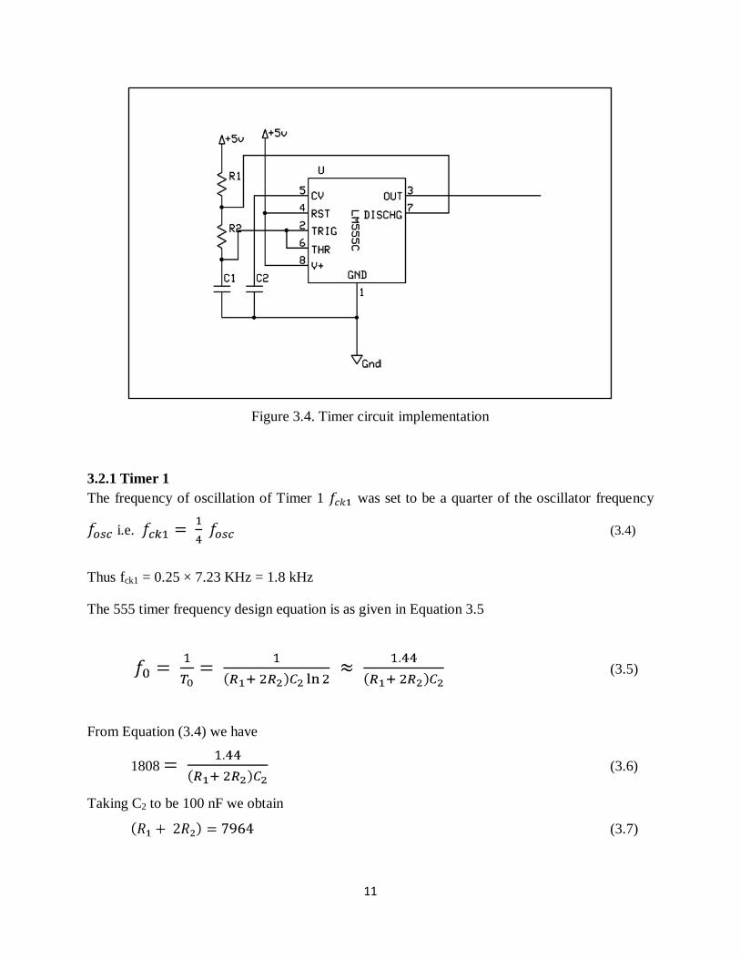
Timer 2 at the very minimum. The timer circuit is shown in Figure 3.4
Page 16
11
Figure 3.4. Timer circuit implementation
3.2.1 Timer 1 The frequency of oscillation of Timer 1 was set to be a quarter of the oscillator frequency
i.e. (3.4)
Thus fck1 = 0.25 × 7.23 KHz = 1.8 kHz The 555 timer frequency design equation is as given in Equation 3.5
(3.5)
From Equation (3.4) we have
1808 (3.6)
Taking C2 to be 100 nF we obtain
(3.7)
Page 17
12
The values of R2 is taken to be 2 kΩ, therefore R1 = 7964 – 2(2000) ≈ 4 kΩ.
Taking the value of R1 = 3.9 kΩ, we obtain a frequency of 1.8 kHz
Multisim Simulation software gave a frequency of 1.78 kHz with the laboratory implementation
of this timer giving a frequency of 1.79 kHz.
2.2.2 Timer 2 Timer 2 was designed to operate at a frequency of a quarter the frequency of Timer 1
(3.8)
Thus fck1 = 0.25 × 1.77 kHz = 445 Hz
From requirement of Equation (3.8) we have
445 (3.9)
Taking C2 to be 100 nF we obtain
(3.10)
The values of R1 is taken to be 16 kΩ, therefore R2 = (32360 – 16000)/2 = 8.2 kΩ
The above values of R1, R2 and C2 give a frequency of 444 Hz
The Multisim Simulation software gave a frequency of 441 Hz with the laboratory
implementation of this timer giving a frequency of 446.4 Hz
The frequency disparities from the calculated values were as a result of the varying component
tolerances. This small frequency variation was ignored since the Combinational Logic Circuit
Prober is not very frequency specific.
Page 18
13
3.3 Staircase waveform generator
In order to display all the 32 patterns required for a 3 input combinational logic circuit, dc
voltages of increasing amount were required to be added to the sinusoidal signals. A staircase
waveform which appears as a set of discretely increasing dc values was used. The circuit used to
generate the staircase waveforms is shown in Figure 3.5
The eight step staircase waveform generator was constructed using an analogue
multiplexer with the inputs being supplied by a potential divider circuit as shown in the Figure
3.5. The selection was implemented using the three LSB bits of a 4 bit counter.
Figure 3.5. Eight Step Staircase Waveform Generator Circuit
Page 19
14
The connection for the four step staircase waveform generator was similar to that of the eight
step staircase waveform generator shown in Figure 1.1 with the analogue multiplexer
being replaced with a analogue multiplexer (CD4052).
Only the four lower levels of the potential divider connection were used as the inputs to the
multiplexer. The two LSBs of a second counter were used for the multiplexer switch selection.
The two staircase waveform generator circuits were simulated in Proteus and also implemented
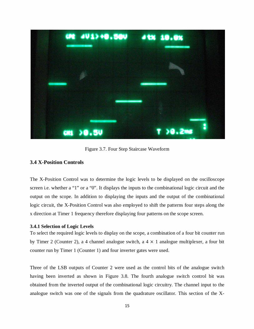
in the laboratory and gave the laboratory results shown in the Photographs in Figures 3.6 and 3.7
Figure 3.6. Eight Step Staircase Waveform
Page 20
15
Figure 3.7. Four Step Staircase Waveform
3.4 X-Position Controls
The X-Position Control was to determine the logic levels to be displayed on the oscilloscope
screen i.e. whether a “1” or a “0”. It displays the inputs to the combinational logic circuit and the
output on the scope. In addition to displaying the inputs and the output of the combinational
logic circuit, the X-Position Control was also employed to shift the patterns four steps along the
x direction at Timer 1 frequency therefore displaying four patterns on the scope screen.
3.4.1 Selection of Logic Levels To select the required logic levels to display on the scope, a combination of a four bit counter run
by Timer 2 (Counter 2), a 4 channel analogue switch, a 4 1 analogue multiplexer, a four bit
counter run by Timer 1 (Counter 1) and four inverter gates were used.
Three of the LSB outputs of Counter 2 were used as the control bits of the analogue switch
having been inverted as shown in Figure 3.8. The fourth analogue switch control bit was
obtained from the inverted output of the combinational logic circuitry. The channel input to the
analogue switch was one of the signals from the quadrature oscillator. This section of the X-
Page 21
16
Position Controls simply provided a complete channel to the output if the counter bit or the
combinational logic circuit output is a one, otherwise it blocked the channel.
The next section of the X-Position Controls used in the selection process involved a 4 1
analogue multiplexer with the selection switches being controller by the two LSBs of Counter 1.
The four channel outputs of the analogue switch provided the inputs to the multiplexer channel.
At a speed four times that of Counter 1, the multiplexer moved through the four channels
selecting and presenting the output of the signals at the channels.
3.4.2 Shifting the Logic levels To display the four logic levels on one line, the output of the X-position controls is combine with
the four step staircase waveform
The circuit of the X-position controls is given in Figure 3.8
Figure 3.8. X-Position Controls Circuit
Page 22
17
3.5 Y-Position Controls The purpose of the Y-Position controls was to shift the already formed four patterns on the X
axis along the Y –axis thereby producing eight levels and hence 32 patterns on the oscilloscope
screen.
The function of the Y-Position Controls was achieved by combining the eight step staircase
waveform with Vcosine signal from the quadrature oscillator.
3.6 Buffer Circuit During the implementation of the staircase waveform generator circuit and the oscillator circuit,
it was observed that when these circuits are connected to the rest of the circuitry, their outputs
were loaded. This loading resulted in the distortion of both the staircase waveform and sinusoidal
signals. To counter this effect, a circuit with a very high input impedance and very low output
impedance was required and this requirement was met by the implementation of an Op Amp
buffer circuit as shown in Figure 3.9
Figure 3.9. Op-Amp Buffer Circuit
Page 23
18
CHAPTER 4
4. RESULTS
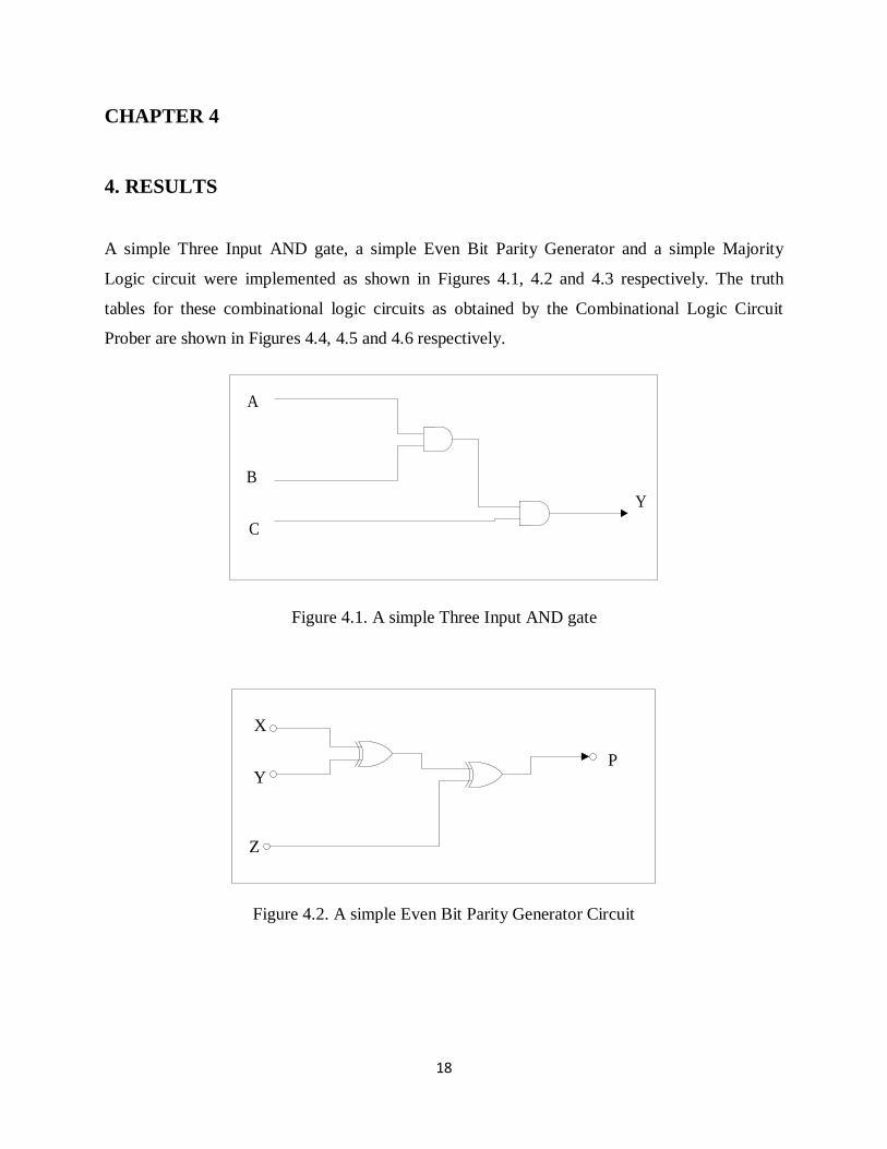
A simple Three Input AND gate, a simple Even Bit Parity Generator and a simple Majority
Logic circuit were implemented as shown in Figures 4.1, 4.2 and 4.3 respectively. The truth
tables for these combinational logic circuits as obtained by the Combinational Logic Circuit
Prober are shown in Figures 4.4, 4.5 and 4.6 respectively.
A
B
CY
Figure 4.1. A simple Three Input AND gate
X
Y
Z
P
Figure 4.2. A simple Even Bit Parity Generator Circuit
Page 24
19
A
B
C
Y
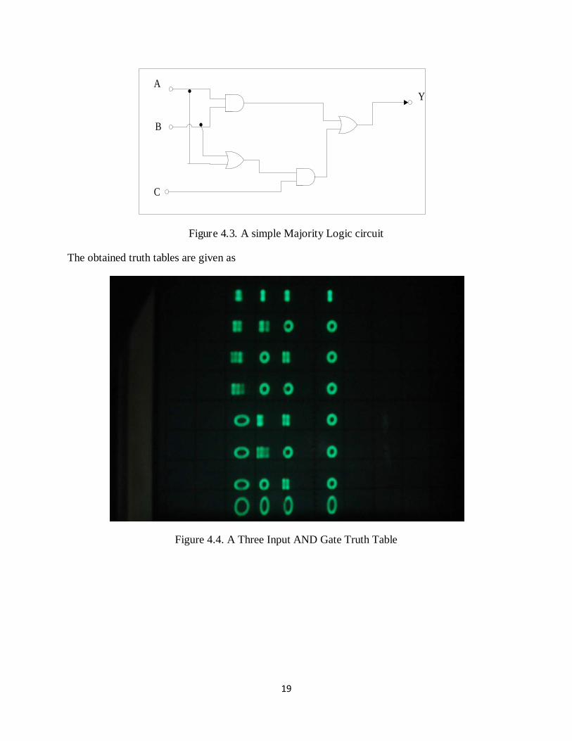
Figure 4.3. A simple Majority Logic circuit
The obtained truth tables are given as
Figure 4.4. A Three Input AND Gate Truth Table
Page 25
20
Figure 4.5. A simple Even Bit Parity Generator
Figure 4.6. A simple Majority Logic Circuit
Page 26
21
CHAPTER 5
5. DISCUSSION
In the obtained truth tables, the “1”s on the oscilloscope screen appeared unstable, though they
were clearly distinguishable from the “0”s. This was as a result of imperfect switching by the
analogue switch. The signals at the gate outputs were transmitted faithfully when the channel
was connected, but when the channel was disconnected an unstable and attenuated version of the
signal was transmitted when no signal was to be transmitted. This resulted in the instability of
the ones
Some of the “0” were also noted to be elliptic in shape while others were perfect zeros. This was
as a result of the nonlinear attenuating effect of the staircase waveform on the sinusoidal signal.
The attenuation factor increases up the staircase and was as a result of the different impedance
seen by the sinusoidal signal up the staircase waveform in both the X and the Y paths. This
attenuation factor produced waveforms with different amplitudes from both the paths leading the
elliptic shapes.
Due to the local unavailability of Digital to Analogue converters, a simple staircase generator
was implemented using an analogue multiplexer, a counter, a timer and resistors as shown in
Figure 3.5. This circuit had the advantage in that the risers of the staircase waveform could be
adjusted by changing the resistor values.
A capacitor of 10 µF was inserted between the output of the quadrature oscillator and the input
of the analogue switch to reduce the magnitude of the dc signal into the switch. High dc signals
into the switch resulted into a very poor switching by the analogue switch. A capacitor of 10 µF
was also noted to have less adverse effects on the oscillator stability as it does not affect the
dominant poles.
A capacitor of 1µF was connected between the supply line and the ground to minimize the
effects of loading of the supply line by the timers.
Page 27
22
CHAPTER 6
6. CONCLUSION AND FURTHER WORK
It was shown in this report that a truth table for a combinational logic circuit can be displayed on
an ordinary 60 MHz oscilloscope in form of ‘1”s and ‘0”s. Despite the few setbacks in the
discussed, the “0”s and “1”s obtained by the Combinational Logic Circuit Prober were clearly
distinguishable. The Combinational Logic Circuit Prober was used to obtain the truth tables of a
simple Even Bit Parity Generator circuit, a Majority Logic circuit and a Three Input AND gate
and the results verified to be accurate by comparison with the theory.
The problem of the difference between the zeros can be eliminated by implementing a nonlinear
amplifier with the gain factor dependent on the input signal amplitude. The higher amplitude
sinusoidal signals are to be kept constant or amplified at lower gain factors while the lower
amplitude signals are to be amplified at higher gain factors. This produces a constant amplitude
signal therefore ensuring that the zeros are perfect zeros. It is therefore recommended that a
µ-law circuit be implemented and combined with the Combinational Logic Circuit Prober to
produce perfect zeros.
The combinational logic circuit prober operates on TTL voltage levels and is also compatible
with CMOS logic levels. However, the combinational logic circuit prober cannot be used with
ECL logic due to incompatibility of the logic levels. It is therefore recommended that an adapter
to make the ECL circuits compatible with the combinational logic circuit prober be designed.
Page 28
23
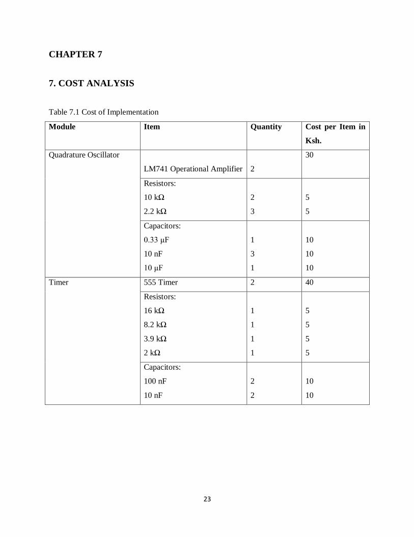
CHAPTER 7
7. COST ANALYSIS
Table 7.1 Cost of Implementation
Module Item Quantity Cost per Item in
Ksh.
Quadrature Oscillator
LM741 Operational Amplifier
2
30
Resistors:
10 kΩ
2.2 kΩ
2
3
5
5
Capacitors:
0.33 μF
10 nF
10 μF
1
3
1
10
10
10
Timer 555 Timer 2 40
Resistors:
16 kΩ
8.2 kΩ
3.9 kΩ
2 kΩ
1
1
1
1
5
5
5
5
Capacitors:
100 nF
10 nF
2
2
10
10
Page 29
24
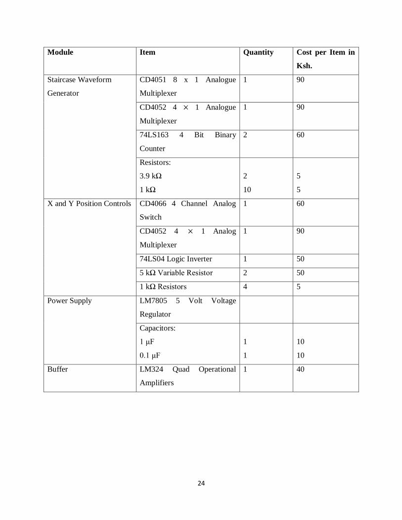
Module Item Quantity Cost per Item in
Ksh.
Staircase Waveform
Generator
CD4051 8 x 1 Analogue
Multiplexer
1 90
CD4052 4 1 Analogue
Multiplexer
1 90
74LS163 4 Bit Binary
Counter
2 60
Resistors:
3.9 kΩ
1 kΩ
2
10
5
5
X and Y Position Controls CD4066 4 Channel Analog
Switch
1 60
CD4052 4 1 Analog
Multiplexer
1 90
74LS04 Logic Inverter 1 50
5 kΩ Variable Resistor 2 50
1 kΩ Resistors 4 5
Power Supply LM7805 5 Volt Voltage
Regulator
Capacitors:
1 μF
0.1 μF
1
1
10
10
Buffer LM324 Quad Operational
Amplifiers
1 40
Page 30
25
APPENDIX
APPENDIX A: QUADRATURE OSCILLATOR ANALYSIS
Taking Vo = V OUT (SINE)
Vf (negative feedback) = βVo = (A.1)
Therefore β = (A.2)
=
For R1C1 = R2C2 = R3C3 = RC (A.3)
β = (A.4)
For β to be real at fo, so2R2C2 = -1 (A.5)
Where so = j2πfo (A.6)
so =
fo = (A.7)
Page 31
26
Figure A.1. Quadrature Oscillator Circuit Diagram
Page 32
27
APPENDIX B: COMBINATIONAL LOGIC CIRCUIT PROBER CIRCUIT
Figure B.1. Combinational logic circuit prober circuit diagram
Page 33
28
APPENDIX C: DIGITAL LOGIC FAMILIES
Digital integrated circuits are classified not only by their complexity or logical operation, but
also by the specific circuit technology to which they belong. The circuit technology is referred to
as a digital logic family. Each logic family has its own basic electronic circuit upon which more
complex digital circuits and components are developed. The basic circuit in each technology is a
NAND, NOR, or an inverter gate. The electronic components used in the construction of the
basic circuit are usually used as the name of the technology. Many different logic families of
digital integrated circuits have been introduced commercially. The following are the most
popular:
• TTL (Transistor-Transistor Logic)
• ECL (Emitter-Coupled Logic)
• MOS (Metal-Oxide Semiconductor)
• CMOS (Complementary Metal-Oxide Semiconductor)
TTL is a widespread logic family that has been in operation for some time and is considered as
standard. ECL has an advantage in systems requiring high-speed operation. MOS is suitable for
circuits that need high component density, and CMOS is preferable in systems requiring low
power consumption.
The transistor-transistor logic family evolved from a previous technology that used diodes and
transistors for the basic NAND gate. This technology was called DTL for diode-transistor logic.
Later the diodes were replaced by transistors to improve the circuit operation and the name of the
logic family was changed to TTL.
Emitter-coupled logic (ECL) circuits provide the highest speed among the integrated digital logic
families. ECL is used in systems such as supercomputers and signal processors, where high
speed is essential. The transistors in ECL gates operate in a nonsaturated state, a condition that
allows the achievement of propagation delays of 1 to 2 nanoseconds.
The metal-oxide semiconductor (MOS) is a unipolar transistor that depends upon the flow of
only one type of carrier, which may be electrons (n-channel) or holes (p-channel). This is in
Page 34
29
contrast to the bipolar transistor used in TTL and ECL gates, where both carriers exist during
normal operation. The most important advantages of MOS over bipolar transistors are the high
packing density of circuits, a simpler processing technique during fabrication, and a more
economical operation because of the low power consumption.
The characteristics of digital logic families are usually compared by analyzing the circuit of the
basic gate in each family. The most important parameters that are evaluated and compared are:
Fan-out specifies the number of standard loads that the output of a typical gate can drive without
impairing its normal operation. A standard load is usually defined as the amount of current
needed by an input of another similar gate of the same family.
Power dissipation is the power consumed by the gate that must be available from the power
supply.
Propagation delay is the average transition delay time for the signal to propagate from input to
output. The operating speed is inversely proportional to the propagation delay.
Noise margin is the minimum external noise voltage that causes an undesirable change in the
circuit output.
Page 35
30
REFERENCES
[1] http://en.wikipedia.org/wiki/Logic_analyzer
[2] http://en.wikipedia.org/wiki/Logic_probe
[3] http://en.wikipedia.org/wiki/Truth_table
[4] http://en.wikipedia.org/wiki/Logic_Gate
[5] http://en.wikipedia.org/wiki/Combinational_logic
[6] M. Morris Mano and Michael D. Celeti, Digital Design 3rd Edition, Addison Wesley
Longman, 2006
[7] Mancini, Ron, Op Amps for Everyone, Texas Instruments, August 2002.