43
Combinational Logic Prof. Usagi

Combinational LogicProf. Usagi

2

Recap: Logic Design?
3
https://www.britannica.com/technology/logic-design

sampling cycle
Recap: Analog v.s. digital signals
4
Infinite possible values!1
0
0.5? 0.4? 0.45? 0.445? 0.4445? or
0.4444444444459?Anything within this wide range is considered as “1”

• Please identify how many of the following statements explains why digital computers are now more popular than analog computers. ① The cost of building systems with the same functionality is lower by using
digital computers. ② Digital computers can express more values than analog computers. ③ Digital signals are less fragile to noise and defective/low-quality components. ④ Digital data are easier to store. A. 0 B. 1 C. 2 D. 3 E. 4
5
Recap: Why are digital computers more popular now?

• Each position represents a quantity; symbol in position means how many of that quantity • Decimal (base 10)
• Ten symbols: 0, 1, 2, 3, 4, 5, 6, 7, 8, 9 • More than 9: next position • Each position is incremented by power of 10
• Binary (base 2) • Two symbols: 0, 1 • More than 1: next position • Each position is incremented by power of 2
6
Recap: The basic idea of a number system
100101102
123× × ×
+ + =300+20+1 =321
20212223
1001× × ××
+ + =1 23
+1 20
=1 8+1 1
=9
+ ××
××

• Two types of logics • The theory behind combinational logics • The building blocks of combinational logics
7
Outline

Types of circuits
8

• Combinational logic • The output is a pure function of its current inputs • The output doesn’t change regardless how many times the logic is
triggered — Idempotent • Sequential logic
• The output depends on current inputs, previous inputs, their history
9
Combinational v.s. sequential logic

• How many of the following can we simply use combinational logics to accomplish? ① Counters ② Adders ③ Memory cells ④ Decimal to 7-segment LED-decoders A. 0 B. 1 C. 2 D. 3 E. 4
10
When to use combinational logic?Poll close in

• How many of the following can we simply use combinational logics to accomplish? ① Counters ② Adders ③ Memory cells ④ Decimal to 7-segment LED-decoders A. 0 B. 1 C. 2 D. 3 E. 4
11
When to use combinational logic?
— You need the previous input
— You need to keep the current state

• A Combinational logic is the implementation of aBoolean Algebra function with only Boolean Variables as their inputs
• A Sequential logic is the implementation of aFinite-State Machine
12
Theory behind each

Boolean Algebra
13

• Boolean algebra — George Boole, 1815—1864 • Introduced binary variables • Introduced the three fundamental logic operations: AND, OR, and NOT • Extended to abstract algebra with set operations: intersect, union,
complement • Switching algebra — Claude Shannon, 1916—2001
• Wrote his thesis demonstrating that electrical applications of Boolean algebra could construct any logical numerical relationship
• Disposal of the abstract mathematical apparatus, casting switching algebra as the two-element Boolean algebra.
• We now use switching algebra and boolean algebra interchangeably in EE, but not doing that if you’re interacting with a mathematician.
14
Boolean algebra (disambiguation)

• {0, 1}: The only two possible values in inputs/outputs • Basic operators
• AND (•) — a • b • returns 1 only if both a and b are 1s • otherwise returns 0
• OR (+) — a + b • returns 1 if a or b is 1 • returns 0 if none of them are 1s
• NOT (‘) — a’ • returns 0 if a is 1 • returns 1 if a is 0
15
Basic Boolean Algebra Concepts

• A table sets out the functional values of logical expressions on each of their functional arguments, that is, for each combination of values taken by their logical variables
16
Truth tables
Input OutputA B0 0 00 1 01 0 01 1 1
ANDInput Output
A B0 0 00 1 11 0 11 1 1
ORInput Output
A0 10 11 01 0
NOT

• X, Y are two Boolean variables. Consider the following function:X • Y + XHow many of the following the input values of X and Y can lead to an output of 1 ① X = 0, Y = 0 ② X = 0, Y = 1 ③ X = 1, Y = 0 ④ X = 1, Y = 1 A. 0 B. 1 C. 2 D. 3 E. 4
17
Let’s practice!Poll close in

• X, Y are two Boolean variables. Consider the following function:X • Y’ + XHow many of the following the input values of X and Y can lead to an output of 1 ① X = 0, Y = 0 ② X = 0, Y = 1 ③ X = 1, Y = 0 ④ X = 1, Y = 1 A. 0 B. 1 C. 2 D. 3 E. 4
18
Let’s practice!
Input OutputX Y Y’ XY’ XY’ + X
0 0 00 1 01 0 11 1 1
1 0 0
0 0 0
1 1 1
0 0 1

• NAND — (a • b)’ • NOR — (a + b)’ • XOR — (a + b) • (a’ + b’) or ab’ + a’b • XNOR — (a + b’) • (a’ + b) or ab + a’b’
19
Derived Boolean operators
Input OutputA B0 0 10 1 11 0 11 1 0
NANDInput Output
A B0 0 10 1 01 0 01 1 0
NORInput Output
A B0 0 00 1 11 0 11 1 0
XORInput Output
A B0 0 10 1 01 0 01 1 1
XNOR

Express Boolean Operators/Functions in Circuit “Gates”
20

Boolean operators their circuit “gate” symbols
21
AND
OR
NOT
NAND
NOR
XOR
NXORrepresents where we take a compliment value on an input represents where we take a compliment value on an output

How to express y = e(ab+cd)
22
ye
AND
OR
NOT
NAND
NOR
XOR
NXOR
ab
cd
# gates : 4# signal nets : 9# pins: 12
# inputs : 5# outputs : 1

We can make everything NAND!
23
Original NAND
AND
OR
NOT
a
b
a
b
a
a
b
a
b
a

We can also make everything NOR!
24
Original NAND
AND
OR
NOT
a
b
a
b
a
a
b
a
b
a

How to express y = e(ab+cd)
25
ye
ab
cd

How to express y = e(ab+cd)
26
e
ab
cd y

How gates are implemented?
27

• nMOS • Turns on when G = 1 • When it’s on, passes 0s, but not 1s • Connect S to ground (0) • Pulldown network
• pMOS • Turns on when G = 0 • When it’s on, passes 1s, but not 0s • Connect S to Vdd (1) • Pullup network
28
Two type of CMOSs
G
S
D
G
S
D
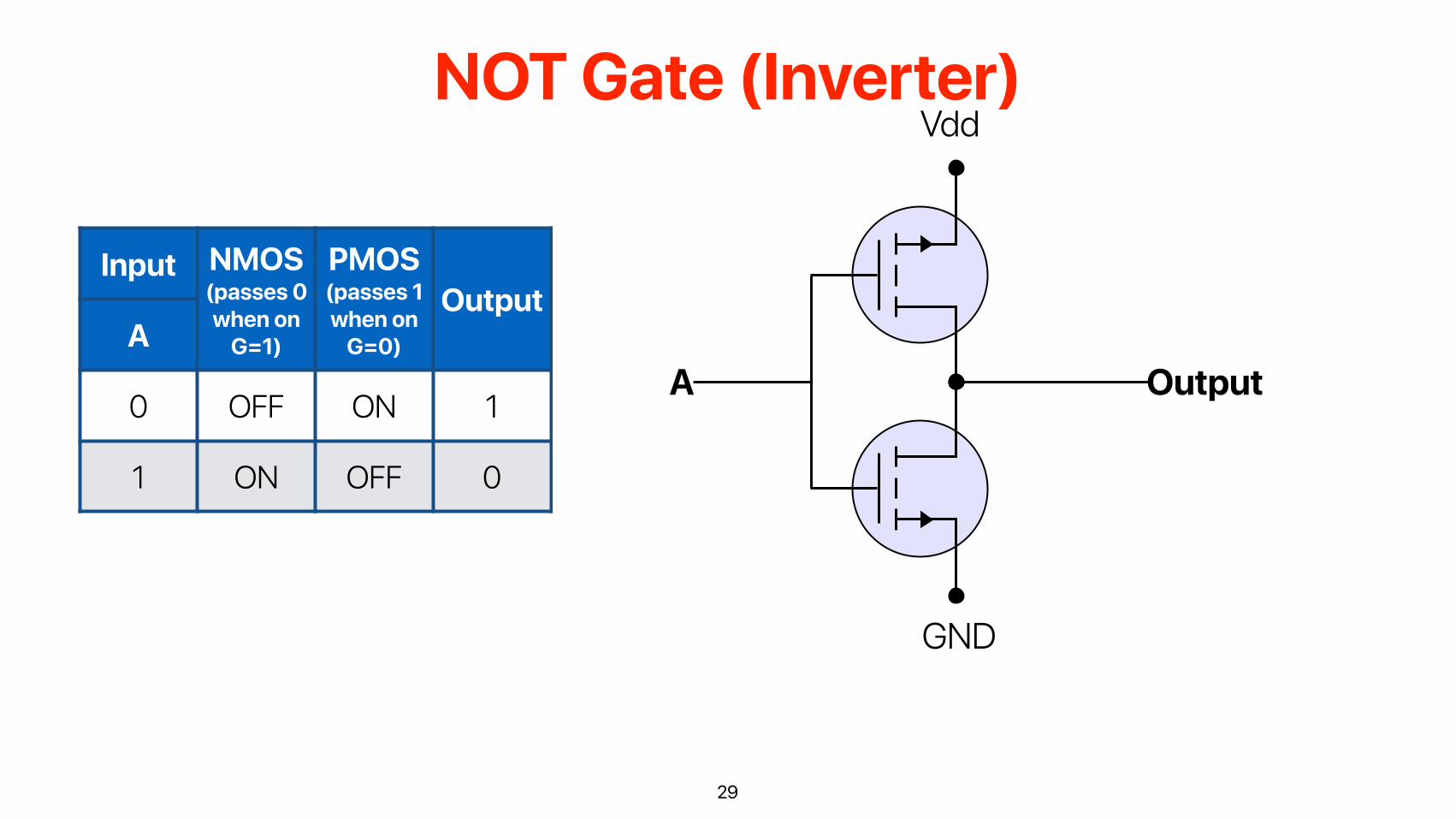
NOT Gate (Inverter)
29
Input NMOS(passes 0 when on
G=1)
PMOS(passes 1 when on
G=0)
OutputA
0 OFF ON 1
1 ON OFF 0
GND
Vdd
OutputA

AND Gate
30GND
Vdd
Output
A B
A
B GND
Vdd

OR Gate
31GND
Vdd
Output
A
B
A B
GND
Vdd
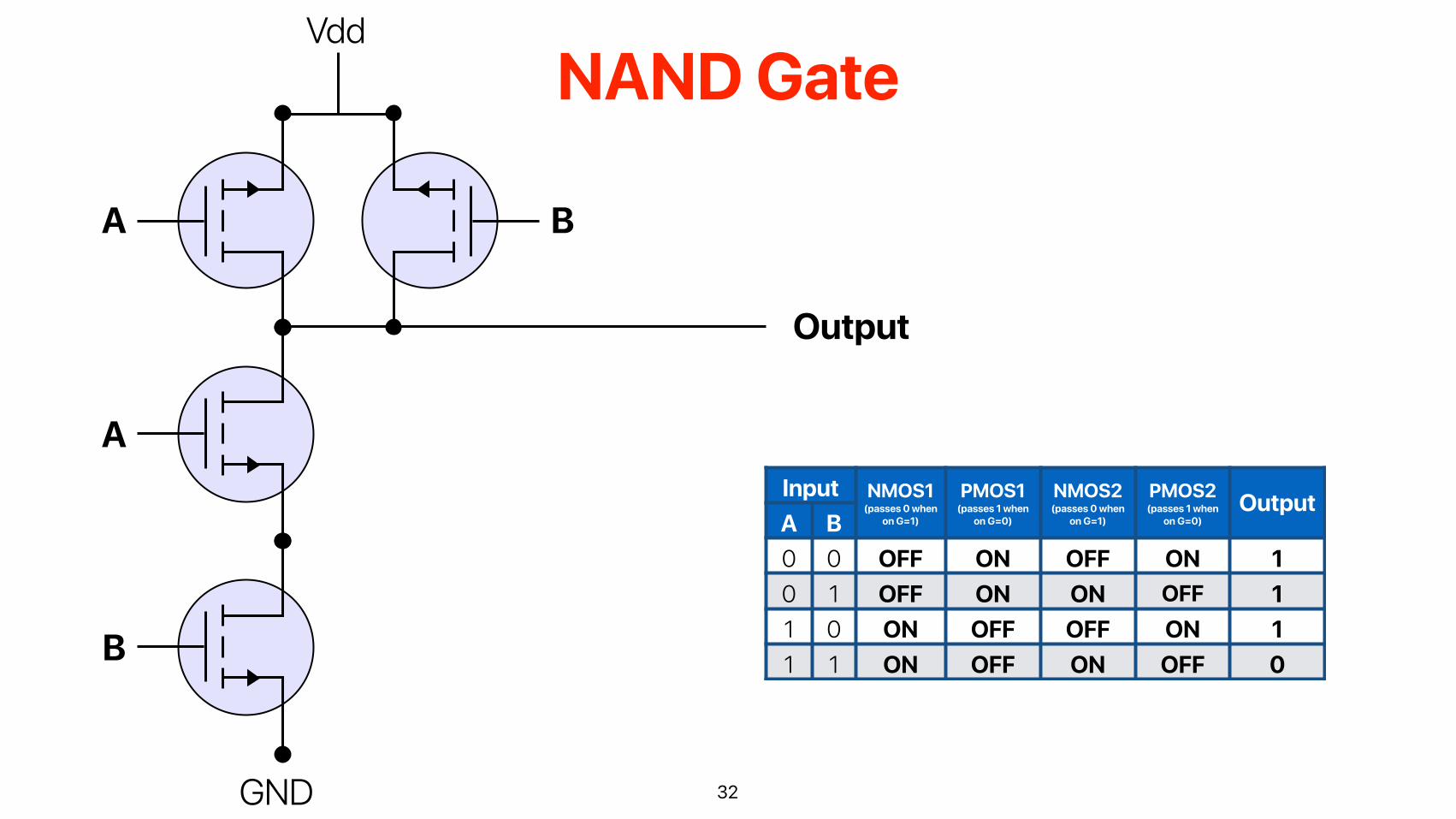
NAND Gate
32GND
Input NMOS1(passes 0 when
on G=1)
PMOS1(passes 1 when
on G=0)
NMOS2(passes 0 when
on G=1)
PMOS2(passes 1 when
on G=0)Output
A B0 0 OFF ON OFF ON 10 1 OFF ON ON OFF 11 0 ON OFF OFF ON 11 1 ON OFF ON OFF 0
Vdd
A
A
B
B
Output

• NAND and NOR are “universal gates” — you can build any circuit with everything NAND or NOR
• Simplifies the design as you only need one type of gate • NAND only needs 4 transistors — gate delay is smaller than
OR/AND that needs 6 transistors • NAND is slightly faster than NOR due to the physics nature
33
Why use NAND?

How about total number of transistors?
34
4 gates, each 6 transistors : total 24 transistors
9 gates, each 4 transistors : total 36 transistors

However …
35
e
ab
cd y
Inverter Inverter
Inverter Inverter
Now, only 5 gates and 4 transistors each — 20 transistors!

• How many rows do we need to express the circuit represented by y = e(ab+cd)
A. 5 B. 9 C. 25 D. 32 E. 64
36
How big is the truth table of y = e(ab+cd)Poll close in
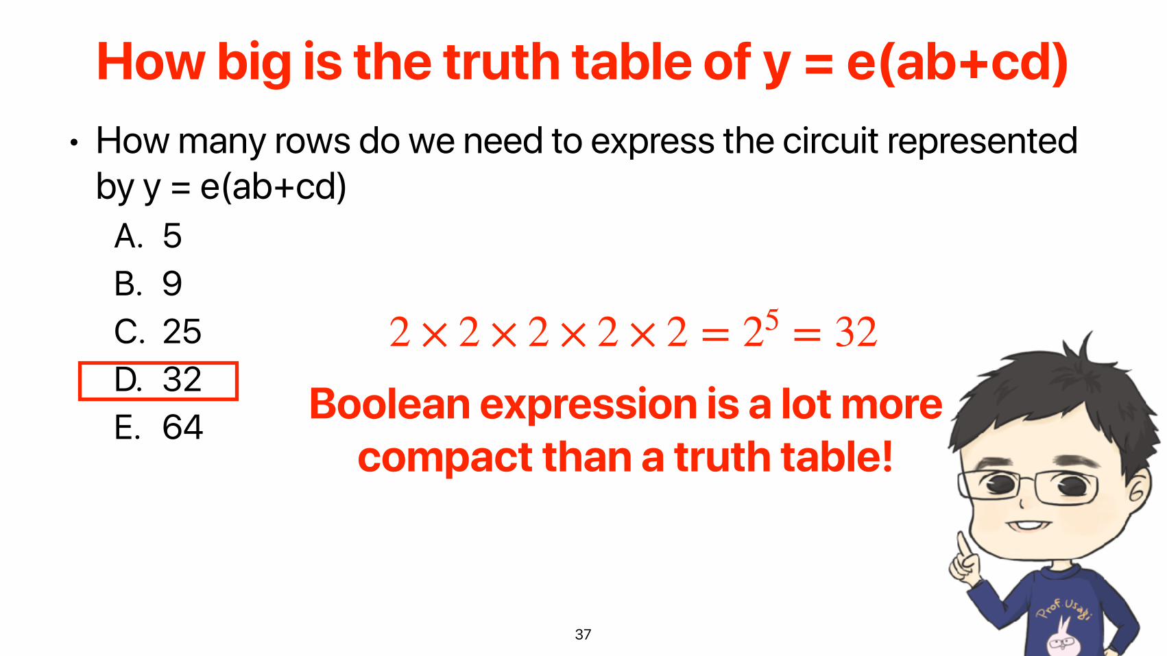
• How many rows do we need to express the circuit represented by y = e(ab+cd)
A. 5 B. 9 C. 25 D. 32 E. 64
37
How big is the truth table of y = e(ab+cd)
2 × 2 × 2 × 2 × 2 = 25 = 32
Boolean expression is a lot more compact than a truth table!
Can We Get the Boolean Equation from a Truth Table?
38

• Complement: variable with a bar over it or a ‘ — A’, B’, C’ • Literal: variable or its complement — A, A’, B, B’, C, C’ • Implicant: product of literals — ABC, AC, BC • Implicate: sum of literals — (A+B+C), (A+C), (B+C) • Minterm: AND that includes all input variables — ABC, A’BC,
AB’C • Maxterm: OR that includes all input variables — (A+B+C),
(A’+B+C), (A’+B’+C)
39
Definitions of Boolean Function Expressions
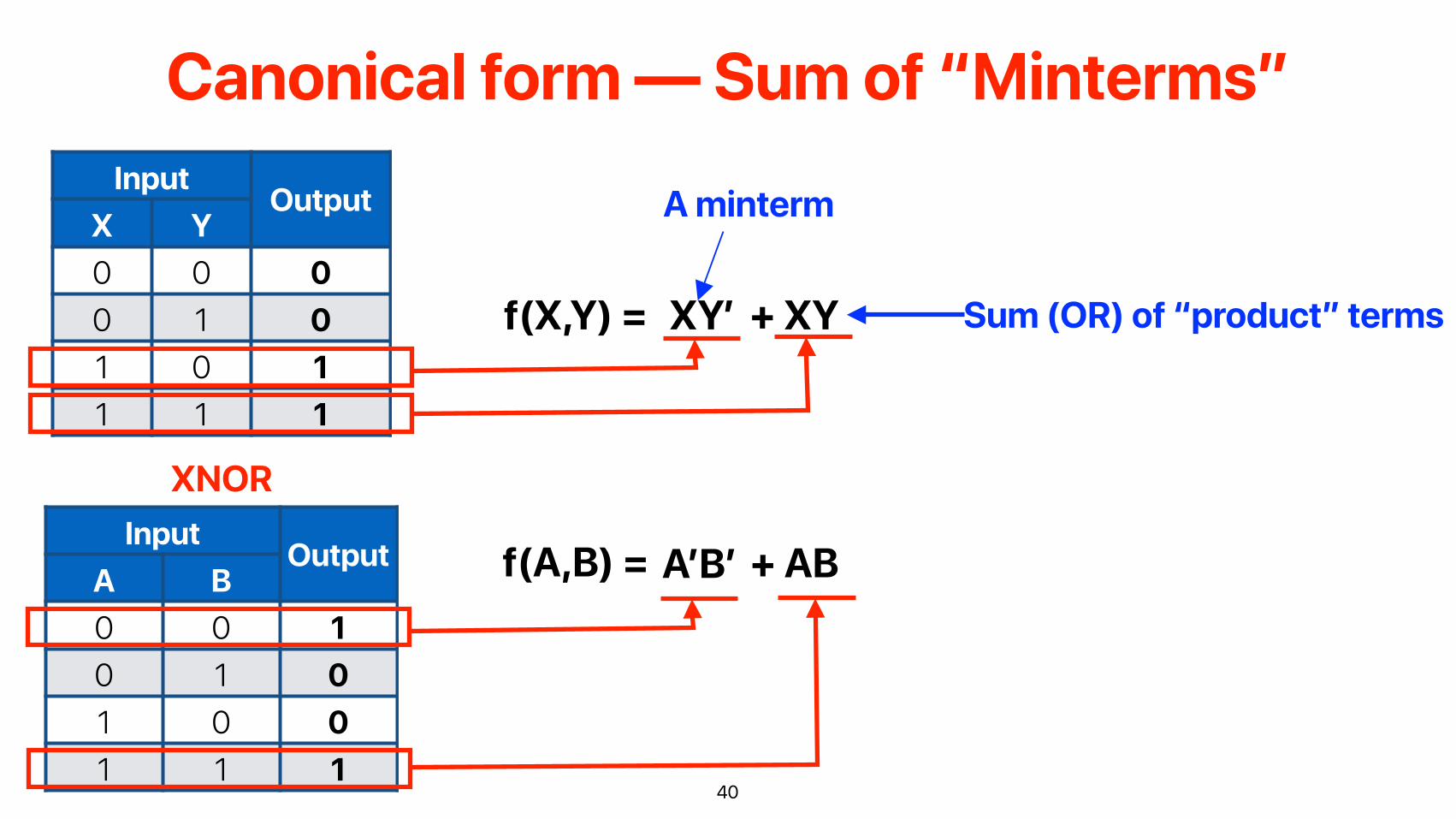
Canonical form — Sum of “Minterms”
40
Input OutputX Y0 0 00 1 01 0 11 1 1
f(X,Y) = XY’ + XY
Input OutputA B0 0 10 1 01 0 01 1 1
XNOR
f(A,B) = A’B’ + AB
A minterm
Sum (OR) of “product” terms

Canonical form — Product of “Maxterms”
41
Input OutputX Y0 0 00 1 01 0 11 1 1
f(X,Y) = (X’+Y') (X’ + Y)
Input OutputA B0 0 10 1 01 0 01 1 1
XNOR
f(A,B) = (A’+B) (A+B’)
A “maxterm
Product of maxterms

• Please also register yourself to the following two • Please register to your corresponding lab
sessions • The link is under iLearn > course materials
• Please register to office hours • The link is also under iLearn > course materials
• Reading quiz 2 will be up tonight • Under iLearn > reading quizzes
• Lab 1 due 4/7 • Submit through iLearn > Labs
42
Announcement

つづく
ElectricalComputerEngineering
Science120A


