Abstract – The expansion of the transient operation of
electrical machines as, for instance, in vehicle traction
applications, demands an accurate computation of the thermal
behavior under these conditions in order to enhance the
economy of the design and provide a precise estimation of the
overload capacity. In addition, heavy transients have been
identified as specially damaging for the rotor cage of large
induction motors. The aim of this work is the development of a
model able to simulate in detail the thermal and mechanical
effects of a heavy transient on an induction’s motor rotor
featuring a damaged (with a reduced section on one of its ends)
rotor bar. Some preliminary results that provide a qualitative
understanding of the development of a bar breakage during a
fatigue test are presented.
Index Terms-- Induction motors, prognostics and health
management, rotors, finite element analysis, thermal stresses,
transient analysis.
I. NOMENCLATURE
B Peak magnetic flux density
C Elastic modulus tensor
Ce Thermal capacitance of an element
Cp Heat capacity
𝑑 Displacement field
�� Electric flux density
E Young modulus
�� Electric field
f Supply frequency
fs Supply frequency times slip
G Thermal conductance
h Heating power
�� Magnetic field
I Current
𝐽 Current density
k Thermal conductivity
kh, ke, ka Iron losses model’s coefficients
miron rotor’s iron mass
P Generated power in an element
q Thermal flux density
R Resistance
s Slip
t Time
�� Unitary vector
α Iron losses model’s exponent
V. Climente-Alarcon, D. Nair, R. Sundaria and A. Arkkio are with
Department of Electrical Engineering and Automation, Aalto University, P.O. 13000, Espoo 00076, FINLAND (e-mails: [email protected],
[email protected], [email protected], [email protected]).
J. A. Antonino-Daviu is with the Instituto Tecnológico de la Energía, ITE, Universitat Politècnica de València, Camino de Vera s/n, 46022,
Valencia, SPAIN (e-mail: [email protected]).
β Thermal expansion tensor
ε Linear strain
ρ Charge density
ρd Density
ϕ Electric potential
υ Poisson ratio
σ Electrical conductivity
τ Stress tensor
ψ Flux linkage
θ Temperature
II. INTRODUCTION
he power yielded by an electrical machine is limited by
its maximum operating temperature. A more efficient
cooling system or a colder environment allows the same
machine to be operated above its rated power without
decreasing the expected lifespan [1].
Small motors trust on internal air flow along the airgap,
and external along its cover, to provide cooling. Although
this approach is simple and needs no maintenance, it presents
the drawback of linking the rotational speed of the machine
to its cooling rate, whilst its heating remains proportional to
the yielded torque. A balance could be achieved for nominal
operation of motors connected to the grid; however, the
introduction of variable speed drives (VSD) prevents
following this approach any longer [2]. Furthermore, the use
of these devices introduces harmonics in the supply voltage
that completely deform the current waveform feeding the
machine. These high frequency harmonics increase losses,
and hence the heating rate of the motor [3].
Thus, for these cases a cost-effective solution is adding
another electrical motor to independently move the fan. This
arrangement allows providing an external air flow to increase
cooling, although internally, along the airgap and around the
end windings, heat transmission is not improved [4, 5].
Nevertheless, in several applications and motor
configurations an independent cooling subsystem cannot be
arranged. In vehicle in-wheel motors, for instance, the
necessity of keeping the non-suspended weight as low as
possible generally prevents the use of any additional
elements. Moreover, for these tasks the geometry of the
machine is completely altered, typically switching the
positions of stator and rotor, now external to the first one.
Also, in such dynamical applications [6] non-stationary
operation prevails along the entire life cycle of the machine,
therefore a thermal stationary state is never reached, and
overload periods might be habitual, for instance, when
starting the movement of the vehicle on slopes [7]. A careful
thermal analysis during transient operation for this kind of
T
Combined Model for Simulating the Effect of
Transients on a Damaged Rotor Cage
Vicente Climente-Alarcon, Devi Nair, Ravi Sundaria, Jose A. Antonino-Daviu, Antero Arkkio
applications is needed, since high temperatures have an
immediate impact on this equipment due to their
demagnetization effect [8].
Besides design, in which the intended objective is to
maintain the maximum temperature below certain threshold
to prevent reducing the lifespan of the machine, a novel
application of thermal computation just lies in determining
that lifespan when due to a defect, this limit is exceeded.
Within the new Condition-Based Maintenance and
Prognostics and Health Management (CBM/PHM)
architecture, the output usually generated by diagnosis
systems consisting of a binary value indicating the state of a
machine or element (healthy/faulty) has evolved into a more
detailed methodology by which the evolution of the fault is
traced from its early stages by an array of advanced diagnosis
methods [9] and extrapolated in order to predict the
remaining useful life (RUL) of the equipment. The result of
its application consists of a time-span value long enough to
allow scheduling corrective actions [10].
Two kinds of approaches are followed for performing this
prognosis of the defect: data-driven approach and the physics
of failure (PoF) approach. The first one is specially employed
when the mechanism of failure is not clear, whilst for the
second one accurate thermal computations are essential since
localized defects, such as hot spots in the stator windings, are
the underlying cause of common failure modes in rotating
electrical machines due to the cyclic stress that thermal
expansion produces [11]. In this context, accurate thermal
and mechanical modelling can provide an insight into the
PoF that explain the growth and propagation of the defect,
adding a complementary methodology to data-driven models
for correctly predicting its evolution.
Rotor cage failures are faults well suited for the
application of a full CBM/PHM system since they constitute
a slow evolving defect and usually affect large machines
started under high inertia [12], thus being equipment on
which the deployment may be justified.
Despite the complexity required for the development of
these models, which comprise several physical phenomena,
there have appeared seminal studies on the matter since the
beginning of the century. In [13], a comparison of aluminum
and copper cages from the design point of view is presented,
including their behavior during a direct-on-line startup,
which is identified as the most demanding operating
condition (especially under high inertia loads) and the
connections of the bars to the end ring as the higher stress
points. The conclusion is that copper is advantageous,
especially from a thermal and mechanical point of view, due
to its greater heat capacity and higher strength, although the
underestimation of mechanical and thermal expansion
stresses during the design stage and poor brazing during the
manufacturing appear responsible in this case for premature
failures [14]. Furthermore, it is also indicated that in a die
cast cage any relative movement between bars and rings is
not allowed, thus increasing stresses in the end-connectors
joints compared to welded bar ones.
On the other hand, [15] tackled the problem directly by
modelling and reproducing the fault itself. The actual
equipment was analyzed through finite element analysis
(FEA), followed by a series of fatigue tests. A time-stepping
method was used to simulate a startup transient, being the
tangential forces acting on the bars computed from the rotor
acceleration. These values fed a mechanical FEM, in which
the position of the nodes in the end rings was fixed, whilst
the movement of the ones in the bars remained unrestricted.
Even increasing the stresses in the end-connectors sections
by adding the effect of cracks or other imperfections, it could
not be reproduced a bar breakage. Fatigue testing on actual
equipment yielded the same result, thus concluding this work
that this fault is caused by a combination of both thermal and
mechanical loads.
A third approach is carried out in [16] to explain actual
damage observed in rotors. An analytical methodology is
used to model the full electromagnetic-thermal-mechanical
problem in order to obtain the stresses on the leakage
filament joining the bars of two cages. This connection
between the external, higher resistance cage for increasing
the torque during the startup, and the internal one, intended
to reduce their combined resistance during stationary
operation, is needed to avoid the flux missing the deeper one
and constitutes a weak point in the rotor’s electrical circuit.
Under severe operation, as it is usual in the harsh
environment of the mining industry with frequent starting
ups and stall conditions, the rising temperature in the leakage
filament increases the stress of aluminum beyond its yield
limit and when the rotor is allowed to cool down
microfractures appear. If its melting point is exceeded, the
result is a neat effect wherein the material flows out of the
slot and projects across the airgap to finally damage the
stator winding.
Ref. [17] provides a further insight of thermal aspects
involved in the design of an induction motor. A per-phase
analytical circuit and two thermal network models are used
to study the heating of a healthy rotor cage in stationary
operation, but also during transients such as startup and stall
conditions. For these cases, the skin effect on the bars, which
is modelled by a multi layered approach, and the heat
transfer towards the rotor teeth are taken into account. The
results are validated for the later transient by experimental
tests on several rotors. An initial assessment of their
mechanical effects in the lifespan of the machine is also
performed.
Finally, the issue was fully addressed experimentally in
[18] with the implementation of a fatigue test aimed at
developing a bar breakage by subjecting an induction motor
to heavy transients, in this case startup and plug stopping
cycles. The results show that the fault could not be
reproduced until the cage was weakened, basically creating a
hot spot as studied in [16] but in this case at a bar’s end. The
effect of the fault’s progression on the stator currents was
fitted to a crack propagation model that allowed carrying out
a prediction of the RUL of the bar once the fault had been
detected at incipient level. Nevertheless, the requirements
regarding a long, heavy cycling during the fatigue test
imposed the selection of a small size machine, thus
preventing the acquisition of the rotor magnitudes, as it is
done in [17]. Therefore, although the driving mechanism
behind the breakage was identified, a PoF model could not
be established.
Thus the aim of this work is to develop a model capable
of providing a further insight into the transient operation of
damaged rotor cages by computing the rotor’s electrical,
thermal and mechanical magnitudes under which that
breakage occurred. This model is improved and adjusted
based on the measurements performed on the stator during
the fatigue test presented in [18]. Given the complexity of the
task, involving three areas of physics, several techniques are
employed according to the degree of detail needed. Early
studies in heat transfer [19] already advocated for FEM for
assessing the effect of hot spots in an induction motor during
transients. However, since this spatial accuracy is not needed
in the stator, lumped parameters are preferred there, thus a
thermal network is used to model this part of the machine
[20, 21]. Both FEM and lumped thermal models are linked
by the power transferred through the Neumann boundary
conditions set at the external surfaces of the rotor. This
approach sharply reduces computational needs and simplifies
the modelling of the convection in the air gap and end caps.
Similarly, the rotor bars are loaded for each time step with
the value of current computed by an electromagnetic (EM)
analytical model in this case of the full machine, presented in
[22], whilst losses and the skin effect are calculated from the
rotational speed yielded by this EM model according to [23]
for the former, whilst for the later a novel approach is
utilized. In order to obtain the mechanical effects caused by
thermal expansion, a post-processing stage computes the
stresses and deformations according to the temperatures
reached at the end of the transient.
The remainder of this paper is organized as follows,
Section III is dedicated to introduce the calculation procedure
followed as well as the FEM tool used, Section IV presents
and initial validation according to the only available
temperature sensor in the machine, Section V yields the
results obtained and Section VI the corresponding
conclusions.
III. METHODOLOGY FOLLOWED
The combined model used in this work is divided in two
parts: the mesh depicting half of the rotor, on which the
electrical, thermal and mechanical field variables are solved,
and ancillary functions that compute the parametric models
and provide this mesh with the required boundary conditions
and body forces. The linking is made at the external surfaces
of the rotor for the thermal variables, since considering a
symmetrical machine, no heat is exchanged through its
middle cross section. Conversely for the electrical ones, the
connection between the models is done at the bars surfaces in
that cross section and current insulation is assumed for the
rest, either because they are surrounded by air or also due to
symmetry in the shaft and iron. Two coupled FE solvers
constitute the core of the combined model (Fig. 1). The first
one, static current, is endowed with the task of calculating in
the rotor the distribution of the currents, considered DC
within the time step, and their corresponding joule heating
Pjoule according to the potential at the middle of the bars Vbar
supplied by the EM model, and the second one is used to
calculate the heat transfer taking into account the temperature
on the rotor external surfaces computed by the thermal
network θext. To model the effect of the hot spot, the
conductivity of aluminum σ(θ) has been considered
temperature-dependent; therefore, this value is updated in the
first solver at the end of the second’s computation.
Routines written in FORTRAN and compiled as dll’s are
called before each time step by the FE software in order to
recalculate the parametric models according to the previous
FEM solution, using the rotor external temperatures θrotor and
currents in bars Ibar, and update the boundary conditions and
body forces accordingly. The skin effect and the iron losses
are modeled separately by other two subroutines and updated
on the nodes of the mesh. Finally, a post processing FE linear
elastic stage determines the mechanical effects caused by the
heating.
A. FEM model
The numerical computation tool used for solving partial
differential equations in this work has been Elmer FEM, a
software developed mainly by the CSC – IT Center for
Science, Finland, since 1995 and released as open source in
2005 [24]. It includes more than 20 physical models and
several numerical methods. Initially aimed at taking
advantage of parallel computing resources, its modularity
offers high flexibility when tackling complex multiphysics
problems. For pre- and post-processing, commercial software
and Paraview [25] were utilized instead.
The coupling of two FEM modules, heat transfer and
static current conduction, allows solving in sequence the
Maxwell’s and heat equations in the rotor mesh for each time
step. From a quasistatic point of view (skin effect is
neglected here):
∇ ∙ �� = 𝜌 (1)
∇ × �� ≈ 0 (2)
Fig. 1. Computational procedure comprising a FEM core (orange)
responsible for obtaining the heating of the rotor during the transient, a post-processing FE module (right, dark blue) to calculate the mechanical
effects of this heating and four ancillary functions modelling for each time
step the thermal behavior of the stator (thermal network), the electromagnetic state of the motor (analytical EM model) and the losses and
skin effect.
LinearElastic FEM
ThermalNetwork
HeatTransf.FEM
StaticCurrent
FEM
Pjoule
θ
θext
Analytic.EM model
Ibar Vbar
σ(θ)
θrotor
Skin effect
Fe losses
Speed
Cp, Plosses
Rst
Ist
∇ × �� = 𝐽 +𝜕��
𝜕𝑡 (3)
The electric field can thus be expressed in terms of the
electric scalar potential 𝜙 and taking into account the relation
between current density and electric field in (3), it yields:
∇ ∙ 𝜎(𝜃)∇𝜙 =𝜕𝜌
𝜕𝑡 (4)
σ being the electric conductivity, which in the aluminum
regions is variable with temperature [26] and provides the
coupling parameter between the Static Current and Heat
Transfer FE modules, whereas in the rotor’s iron σ is a
second order constant tensor to take into account the
negligible conductivity in the axial direction, being the
values in the other two directions the corresponding to the
interbar resistance assumed in [27]. Eq. (4) is used to solve
the electric potential whilst the Joule heating is computed by:
ℎ𝑗𝑜𝑢𝑙𝑒 = ∇𝜙 ∙ 𝜎(𝜃)∇𝜙 (5)
which constitutes, the internal generation input to the heat
equation h in the aluminum regions of the mesh, solved by
the corresponding module:
𝜌𝑑𝑐𝑝 (𝜕𝜃
𝜕𝑡+ (�� ∙ ∇𝜃)) − ∇ ∙ (𝑘∇𝜃) = 𝜌𝑑ℎ (6)
ρd being in this case the density of the material, cp the heat
capacity and k a second order tensor accounting for the
thermal conductivity of the material, which is heavily
anisotropic in the iron regions due to the effect of the
laminations [1]. In this area of the rotor the generation term
is also modified to take into account the Eddy current losses
as:
ℎ = ℎ𝑗𝑜𝑢𝑙𝑒 + ℎ𝑙𝑜𝑠𝑠𝑒𝑠 (7)
Decoupled from this FE computation core devised to
obtain the DC current and heat distribution in the rotor, the
mechanical effects in the cage produced by the heating are
calculated as a post-processing stage by the Elmer’s Linear
Elastic module, using the dynamical equation for elastic
deformation of solids (8) to obtain the displacements in
mesh:
𝜌𝑑
𝜕2𝑑
𝜕𝑡2− ∇ ∙ 𝜏 = 𝑓 (8)
𝑑 being the displacement field, 𝑓 a volume force, and τ the
stress tensor:
𝜏𝑖𝑗 = 𝐶(𝜃)𝑖𝑗𝑘𝑙𝜀𝑘𝑙 − 𝛽𝑖𝑗(𝜃 − 𝜃0) (9)
where C(θ) is elastic modulus tensor (unlike [28] dependent
on the actual temperature of the rotor nodes θ at the time step
considered [29]), β the thermal expansion tensor, in this
particular case both reduced to scalars and θ0 the reference
temperature. The linear strain is obtained simply as:
𝜀 =1
2(∇𝑑 + (∇𝑑)
𝑇) (10)
Since no magnetic behavior is taken into account in these
partial differential equations, the feeding of the rotor bars
constitutes a non-trivial question. According to a previous
analytical study [27], due to the ring connections at both ends
of the bar, the maximum interbar voltage was achieved
around the middle point of this element. Hence in order to
provide a suitable boundary to impose the electrical potential
ϕ obtained from the EM routine and to reduce the number of
degrees of freedom of the model, the mesh solved by these
three Elmer modules depicts just half of the rotor (Fig. 2).
B. Analytical models
Before each time step, the functions below are called by
the corresponding solvers to update several parameters in the
mesh.
1) Thermal Network:
A transient lumped thermal network was formed to study
the impact of rotor bar breakage on the machine’s stator side.
This network offers an analytical solution of the transient
heat conduction across the machine’s stator, as well as the
associated convection processes. Such a lumped model is a
simple way to observe the time-dependent temperature
distribution in the stator. It is governed by equation:
[𝐶𝑒]𝑑[θ]
𝑑𝑡+ [𝐺] ∙ [𝜃] = [𝑃] (11)
(a)
(b)
Fig. 2. a) Rotor at the end of the fatigue test carried out in [18] and b) mesh
representing half of it during the final stage of that same test (the rotor’s
iron has been removed to show the bars).
where, Ce is thermal capacity of each node, [G] matrix of
thermal conductances and P is the power generation at the
nodes. This transient lumped model neglects possible
temperature gradient within a lumped solid during the
transient process.
The corresponding thermal network shown in figure Fig.
3 encompasses just half of the stator due to symmetry. Since
the machine is totally enclosed, cooling occurs through
forced convection over machine’s outer frame, represented
by Ro1. Rs1 accounts for the frame-yoke constant resistance.
As indicated in [1], two T circuits model the yoke and teeth
(nodes 12 and 13), with the small negative resistances Rs3
and Rs5 necessary to adapt a distributed source into a point
heat injection. Rs6, Rs8 and Rs9 constitute another T circuit
accounting for the longitudinal temperature variation in the
slot windings and similarly Rs10, Rs12, Rs14 and Rs15 for
the end windings, being Rs8 and Rs14 the conductors
insulation thermal resistance and Rs15 accounting for the
convection to the end space. The bearing (Rb1-Rb3 for the
rolling elements and both rings) and the end cap (Rdf) have
also been included in the network. Nodes numbered 4, 5, 8
bridge the stator and rotor and receive the power losses q
from the corresponding boundary conditions on the rotor side
(end ring, rotor iron and shaft), as indicated by the arrows,
whereas their temperatures 𝜃𝑒𝑥𝑡 update the gradient value in
the Neumann boundary condition of the mesh for the next
time step t:
𝑘(𝜃𝑡 − 𝜃𝑒𝑥𝑡𝑡−1) = 𝑞𝑡 (12)
k here stands for the convection coefficient on the surfaces of
rotor and end ring and the conduction coefficient on the
shaft. In this way both models are coupled. The end ring
convection heat transfer coefficient has been considered
speed-dependent during the simulation.
2) Analytical Model of the Motor:
For thermally loading the motor in this work an
improvement of the solution devised in [17] was preferred.
Instead of a per-phase model of the machine, the analytical
model published in [22] was specifically devised to
reproduce the effect of several faults, including electrical
asymmetries, thus this model takes into account the position
and current of every conductor along the airgap. In addition,
a circular convolution computed by means of the FFT allows
a precise calculation of self and mutual inductances. This
process is carried out in MATLAB for the motor whose
characteristics are shown in the Appendix before the actual
simulation begins, filling a 3D lookup table, which is read by
the FORTRAN routine when the FEM simulation starts and
stored in the computer’s memory for the rest of its duration.
Given the different time constants involved in thermal and
electromagnetic phenomena, this analytical model operates at
1,000 times the rate of the FE one (1,000 time steps of the
EM model are computed when the FE model request
updating the boundary conditions at a new time). As in the
previous point, the ordinary differential equations for each
circuit are integrated using the Crank-Nicolson method. Half
the resistive part RrIr of the voltage equation (13) is applied
to the corresponding bar:
[0] = [𝑅𝑟] ∙ [𝐼𝑟] +𝑑[ψ𝑟]
𝑑𝑡 (13)
The integration of the current circulating through the same
boundary where the voltage is applied is yielded by the FE
solver and used to update the bar resistance in the EM model
through a low-pass filter.
3) Losses and Skin Effect Modelling:
Elmer provides the capacity of imposing values on the
nodes for the parameters used in the computation. This has
an immediate application for adding the iron losses to the
model by computing a further generation term (7) for the
heat equation (6). An iron losses model that takes into
account their variation with frequency is used for this
purpose [23]. The magnetic flux density fundamental
frequency in the rotor fs is obtained from the movement
equations of the motor, which are integrated along the
electromagnetic ones in the previous module, whereas the
peak magnitude is assumed, according to previous 2D FE
simulations of the same motor, constant with a value of 1.8
T. The corresponding values for M43 electric steel at that
flux density are used in this work for all four coefficients in
(14). Nevertheless, the hysteresis coefficient kh and the
exponent α are also implemented in the code as frequency
dependent, as indicated in [23].
ℎ𝑙𝑜𝑠𝑠𝑒𝑠
𝑚𝑖𝑟𝑜𝑛
= 𝑘ℎ(𝑓𝑠)𝑓𝐵𝛼(𝑓𝑠) + 𝑘𝑒𝑓𝑠2𝐵2 + 𝑘𝑎𝑓𝑠
1.5𝐵1.5 (14)
Ro1
Rs1
Rs2
Rs3 C1Rs2
Rs4
Rs5
Rs4
C5
Rs8
Rs12 Rs10Rs15 Rs14 Rs9
C2
C3
C6
14
13
12
11
6
5
34
2
1
Yoke
Winding
End Winding
Rotor iron
Rdf
10Rd5
C4
End ring
Rd5
Rb1
Rb2
Bearing
Shaft
C8
9
8
Rb3
7
C7
Rs6
Fig. 3. Thermal network used to model the thermal behavior of the stator. The power obtained from the temperature difference on the boundary
conditions of the FE model is injected in nodes 4, 5, 8.
Since the aim of the model is to compute the heating of
the rotor during transients an adequate calculation of the skin
effect is necessary; however, no magnetic variables are
solved in the mesh; therefore the strategy followed in this
work has been to reflect the differential heating it causes on
the bars by modifying the heat capacity of the bar along its
height, according to the rotational speed supplied by the EM
analytical model. The analytical equations used to compute it
assumed a sinusoidal variation of the current [1, 16]. The
curve obtained for each frequency was normalized to 1 in
order to avoid altering the overall heat capacity of the rotor.
A polynomial-formulated surface was fitted to the resulting
points (Fig. 4). No skin effect was considered whatsoever in
the end ring.
IV. INITIAL VALIDATION (COLD STARTUP)
With the objective of carrying out an initial assessment of
the model’s performance a cold startup simulation is
performed. For this transient, accurate initial conditions of
the motor’s temperatures can be established and hence an
easier comparison with the data provided by a thermocouple,
installed during the experiments through the connection box
on the stator and next to end windings, is possible. This
would reflect the electrical and thermal accuracy of the
model.
The parameters and material’s characteristics used for
both simulations are presented in Table I:
A. Assumptions
With the aim of critically establishing the utility of the
model proposed in this work, the assumptions made on all its
modules are enumerated and discussed:
1. No saturation is considered in any of the models. This
prevents the accurate linking of the effect of the fault on
the stator currents.
2. A current distribution according to a DC excitation is
computed. Electrically, only the effect of the resistance
is taken into account in the mesh.
3. The skin effect in the end ring is neglected. Despite the
small height of the hot spot, at the relatively high
frequencies experienced during braking (100-50 Hz)
this might cause particularly high temperatures on its
upper surface.
4. Skin effect and iron losses, when modelled, are done so
according to a sinusoidal variation of flux density
assumption. Slotting harmonics cause additional losses
next to the surface of the rotor not accounted for.
5. Heat convection is not computed. Analytical equations
are used instead to obtain global heat transfer
coefficients that are applied to whole surfaces: shaft,
end ring and rotor iron, thus averaging those heat
fluxes.
6. Thermal contact resistances, a big source of uncertainty
in thermal studies, are also ignored.
7. No heat transfer by radiation is considered. Although
this effect would slightly lower the temperature at the
bottom of the hot spot, facing the shaft, the heat transfer
by radiation in the rest of directions is low, due to
similar temperatures of the receiving surfaces (end ring,
end winding).
8. In the linear elastic analysis, the influence of iron is not
taken into account.
TABLE I
PARAMETERS OF THE STARTUP AND PLUG STOPPING SIMULATIONS
Voltage 230 V kz (Fe) 0.6 W/m∙K
Frequency 50 Hz k (shaft) 31 W/m∙K
Inertia, J 0.13 kg∙m2 Cp (Fe, shaft) 449 J/kg K
External
temperature 298 K Rstator (init) 2 Ω
Time step, EM
model 1∙10-6 s ΔR/R (Cu) 4.29 10-3 K-1
Time step, FE
model 1∙10-3 s Rbar (init) 2.15 10-4 Ω
Cp (Al) 897 J/kg K Rbar,hs (init) 3.05 10-4 Ω
σx,y (Fe) 1.67 103 S θ0 317 K, 443 K
σz (Fe) 0 υ (Al) 0.334
kx,y (Fe) 31 W/m∙K β 23.1·10-6
B. Cold startup results
During the periods the fatigue test carried out in [18] was
periodically stopped the motor studied almost reached
ambient temperature. This allows establishing a constant
distribution to initialize the mesh and the thermal network
and thus an easier assessment of the electrical and thermal
models performance, contrary to the plug stopping transient,
which was carried out after 20 seconds of operation.
Fig. 5 shows the values recorded by the thermocouple
installed in the motor’s connection box for 5 cold startups
during the last part of the fatigue test when the bar breakage
developed. The difference between the earlier and the later
group agrees with a slight variation of ambient temperature
(0.4 K) as the test progressed.
In addition, simulated temperatures up to 7 seconds, when
the startup transient ends, for the end space area (nodes 3, 4
and 10 in Fig. 3) and the outer part of the stator (node 13),
are also depicted. The recorded values don’t correspond to
any of them, as it is expected from the position of the sensor
Fig. 4. Variation of the aluminum heat capacity along the height of the bar
for frequencies 1-100 Hz.
and the parametrization applied in the synthesis of the
thermal network. However, the thermal inertia showed in the
evolution corresponds to the stator yoke and the motor’s
outer surfaces, as well as a total temperature increase
influenced by the end space region.
V. RESULTS (PLUG STOPPING)
The most demanding conditions the motor suffered during
the fatigue test in [18] where achieved at the end of each
cycle, during the plug stopping. In order to have an insight of
the mechanical effects this transient caused another
simulation is carried out. The initial condition is in this case
warm rotor (443 K) being the FE model initialized with this
value for the whole mesh whereas for initializing the thermal
network a full version, also including the rotor, was run
following the cycling of [18] until the rotor iron values
reached that temperature. The other parameters of the
simulation are shown in Table I.
A. Electrical results
The hot spot has a small influence in the bar currents
measured at the middle of the rotor, as shown in Fig. 6,
where the standard deviation of this magnitude for each bar
during the transient is compared. A decrease of just 2.2% is
appreciated for the bar facing the hot spot, whereas the
neighboring ones are overloaded, 1.4% (Bar 2) and 0.34%
(Bar 20). Furthermore, it can also be seen that both models
work with overall similar values of current.
In addition, the resistance values for the rotor bars that the
Electromagnetic analytical model utilizes during the
simulation are depicted in Fig. 7. The initial resistance
difference introduced by the saddle is 41.9 %. The feedback
loop that updates these values according to the currents
measured in the middle section of the rotor is activated 100
ms after connection to avoid sharp variations due to the
electromagnetic transient that may destabilize the EM model.
At the end of the plug stopping, the bar facing the hot spot
has an observed resistance 14.1% greater, whereas the others
have just increased around 5%. As expected, Bar 20 (Fig. 6,
a2) and Bar 2 (Fig. 6, a3) suffer the effect of their higher
load. The spread of the rest is a consequence on the different
heating caused by the asymmetric components of the
electromagnetic transient.
Fig 8 shows the analysis of the stator currents using a
time-frequency decomposition method based on the Wigner-
Ville distribution [18]. The low sideband harmonic (LSH-50,
(1-2s)f ) generally used for diagnosing rotor asymmetries is
clearly detected in case a); evolving from 150 Hz to 50 Hz
(b1) as the slip progresses from 2 to 1. However, when the
material around the hot spot is defined as aluminum, instead
of air, and the same simulation is performed, the component
cannot be appreciated (Fig. 8 (b)). In both cases, the saliency
harmonics reflect the decreasing speed of the rotor (b2).
B. Thermal results
Fig. 9 presents the main heat fluxes in and out the thermal
network depicted in Fig. 3. The effect of the speed-dependent
convection coefficients on nodes 4 and 6 is shown, reducing
the heat transferred out of the end ring and stator. Yet the
airgap-related 5, predominantly laminar, remains constant
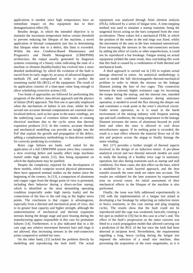
The iron losses in the rotor at the beginning of the braking
account for just 82 W (13.7 W/kg) compared to the 2.4 kW
in resistive losses.
Fig. 5. Comparison of the temperature rise recorded by the thermocouple
during five experimental cold startups and the temperature rise on several
nodes computed by the model for the same transient.
Fig. 6. Standard deviation of the currents in the bars at the middle of the
rotor during the simulation. Bar 1 is facing the hot spot and hence shows an
increased resistance. Both FE and EM models work with similar values.
Fig. 7. Evolution of bar resistances during the transient as processed by the
EM model. The highest values are observed on Bar 1 (a1), Bar 20 (a2) and
Bar 2 (a3).
(a1)
(a2)
(a3)
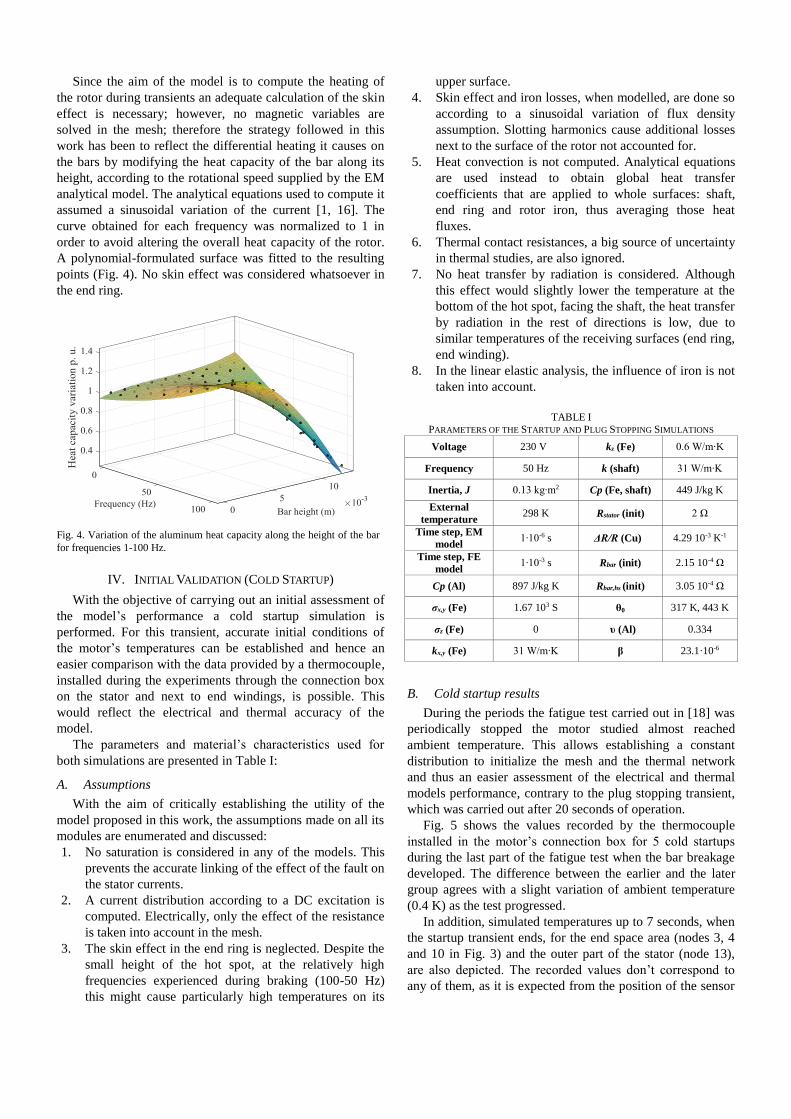
Fig. 10 presents the temperatures in several nodes of the
thermal network. The cycling has risen the values in the
stator, where a high gradient develops at the end of the
stationary operation and beginning of the braking. The
temperatures of the most external nodes don’t suffer a high
increase during the transient, as experimentally verified, due
to heat capacity of all the elements and the effect of the fan.
The recorded increase measured by the thermocouple for
Test 81,060 during this transient was 11 K, whereas in the
simulation the end space temperature (node 4) rose 11.3 K
and the stator 3 (node 13) 3.6 K.
Finally, Fig. 11 (a) shows the temperatures reached in the
rotor after five seconds of the braking simulation, which took
around 100 hours in a PC, when the rotor was approaching
standstill. The highest temperatures are accounted for at the
saddle point at the end of the damaged bar, with a value of 90
K above the shaft. The low heat conductivity of the iron
sheets in the axial direction prevents much of the heat
produced in the end ring to be transferred elsewhere.
Fig. 11 (b) presents the section of the bars next to the
symmetry plane in the middle of the rotor after 0.5 seconds
of simulation, showing temperature difference within each
one and among the one facing the hot spot and the
overloaded, due to interbar currents, neighboring ones.
C. Mechanical results
Finally, applying the linear elastic solver the deformation
and stress of the rotor due to the heating can be obtained
(Fig. 12). Since no clearance was allowed between the bars
and the iron and the former were casted in closed slots, high
stresses were initially obtained on them. However, if only the
cage is considered in this analysis, the hot spot becomes the
highest stress area, being the Von Mises value of this
magnitude 38.6 MPa, well above the yield tension of
aluminum at that temperature (14 MPa) thus causing plastic
deformation. This permanent deformation, when the cage
cools down, creates tensile stresses that initiate and
propagate fatigue cracks. Maximum shear stresses are
obtained at the same place where the crack developed in [18]
(Fig. 12). The surrounding end ring material suffers lesser
permanent effects, since both stress and temperature (Fig. 11
(a)) are lower, and hence the yield limit of aluminum (17
MPa at 500 K) is barely reached.
(a)
(b)
Fig. 8. a) Time-frequency analysis of the stator current, rotor having a hot spot. The rotor asymmetry component (1-2s)f (b1) can be appreciated
evolving form 150 Hz to 50 Hz during the transient, in the case of a healthy
rotor b), this component is not shown.
Fig. 9. Heat flux injected in nodes 2-5 and output through 6. The effect of
the variable convection coefficients on 4 and 6 is appreciated.
Fig. 10. Simulated temperatures in the stator nodes.
(b1)
(b2)
(b2)
VI. CONCLUSIONS
This work presents an approach intended to provide an
insight on the effects of a hot spot in a rotor cage during
transient operation. To reduce the computational
requirements of such complex problem, a combined
analytical-FE simulation is proposed, the EM and the Joule
heating phenomena have been segregated in two models, and
the thermal behavior of the stator has also been implemented
in a separate lumped parameter thermal model. Several
assumptions have been made, however, initial results shows
the capability of the approach for linking the size of the
defect with its electrical, thermal and mechanical effects,
among others, the appearance of temperature gradients in the
rotor cage due to the limited heat transfer capacity of the
surrounding material and the corresponding stresses beyond
the yield limit in certain areas of the hot spot, which
qualitatively explains the crack propagation’s behavior
observed in a previous fatigue test.
Future works will be focused on implementing a fatigue
model based on these results for application in the RUL
estimation and increasing the accuracy of the approach. For
instance, taking into account the effect of saturation in the
EM analysis would allow linking cause (the size of the hot
spot) and the effect produced in the stator currents. This
could be carried out either by improving the analytical model
or coupling a traditional 2D FE motor simulation. The
thermal part can be enhanced by performing short EM 3D
simulations to ascertain the current distribution in the cage at
different frequencies and carrying out the corresponding
quantitative validations by experimental procedures.
VII. APPENDIX
Motor characteristics: Star connected, rated voltage (Un):
400 V, rated power (Pn): 1.5 kW, 1 pole pairs, stator rated
current (I1n): 3.25 A, rated speed (nn): 2860 r/min.
VIII. REFERENCES
[1] Design of Rotating Electrical Machines, J. Pyrhönen, T. Jokinen, V. Hrabovcová, Edt. Wiley, second edition, 2014.
[2] A. Boglietti, A. Cavagnino, M. Lazzari, M. Pastorelli, “A simplified thermal model for variable-speed self-cooled industrial induction motor,” IEEE Trans. Ind. Appl., vol. 39, no. 4, pp. 945 – 952, Jul.-Aug. 2003.
[3] DIN EN IEC 60034-6. Rotating electrical machines. Part 6: methods of cooling.
[4] J. Fouladgar; E. Chauveau, “The influence of the harmonics on the temperature of electrical Machines,” IEEE Trans. Magn., vol. 41, no. 5, pp. 1644–1647, May 2005.
[5] M. Polikarpova et Al. “Hybrid Cooling Method of Axial-Flux Permanent-Magnet Machines for Vehicle Applications,” IEEE Trans. Ind. Electron., Vol. 62, no. 12, pp. 7382 – 7390, Dec. 2015.
[6] V. T. Buyukdegirmenci, P. T. Krein, “Induction Machine Characterization for Short-Term or Momentary Stall Torque,” IEEE Trans. Ind. Appl., vol. 51, no. 3, pp. 2237–2245, May-Jun. 2015,
[7] S. Jurkovic, K. M. Rahman, J. C. Morgante, P. J. Savagian, “Induction Machine Design and Analysis for General Motors e-Assist Electrification Technology,” IEEE Trans. Ind. Appl., vol. 51, no. 1, pp. 631 – 639, Jan.-Feb. 2015.
[8] N. Nisar, Structural Optimization and Thermal Modeling of Flux Switching Machine, Master's thesis dissertation, Aalto University, 2015.
(a)
(b)
Fig. 11. a) Temperature distribution in the half rotor at the end of the plug
stopping transient (warm rotor, initial temperature 443 K), and b)
temperature in the bars after 0.5 seconds.
Fig. 12. Von Mises stress, shear stress (xy-plane) and deformation (x50) on
the hot spot due to thermal expansion at the end of the plug stopping
simulation (5 seconds).
Bar facing
the hot spot
[9] M. Riera-Guasp, J. A. Antonino-Daviu, G.-A. Capolino, “Advances in Electrical Machine, Power Electronic, and Drive Condition Monitoring and Fault Detection: State of the Art,” IEEE Trans. Ind. Electron., Vol. 62, no. 3, pp. 1746 – 1759, Mar. 2015.
[10] C. Ly, K. Tom, C. S. Byington, R. Patrick, G. J. Vachtsevanos, “Fault diagnosis and failure prognosis for engineering systems: A global perspective automation science and engineering,” in Proc. CASE, 2009, pp. 108-115, Bangalore, India.
[11] V. Peesapati, R. Gardner, R. Lowndes, I. Cotton, B. Twomey, L. Dunsby, R. Balcombe, “Impact of thermal cycling on high voltage coils used in marine generators using FEA methods,” IEEE Electrical Insulation Conference (EIC), Seattle, WA, Jun. 7-10 2015, pp. 434–43.
[12] A. Bellini, F. Filippetti, C. Tassoni, G.-A. Capolino, “Advances in diagnostic techniques for induction machines,” IEEE Trans. Ind. Electron., Vol. 55, no. 12, pp. 4109-4126, Dec., 2008.
[13] M. Hodowanec, W. R. Finley, Copper Versus Aluminum-Which Construction Is Best? [Induction Motor Rotors], IEEE Ind. Appl. Magazine, vol. 8, 2002, pp. 14-25.
[14] R. Yabiku, R. Fialho, L. Teran, A. Santos, E. Rangel, D. Dutra, “A comparative study between copper and aluminum induction squirrel cage constructions,” in Proc. Petroleum and Chemical Industry Conference (PCIC), San Antonio, TX, USA, Sept. 20-22 2010, pp. 1-9.
[15] M. F. Cabanas, J. L. Ruiz Gonzalez, J. L. B. Sampayo, M. G. Melero, C. H. Rojas, F. Pedrayes, A. Arguelles, J. Vina, “Analysis of the fatigue causes on the rotor bars of squirrel cage asynchronous motors: Experimental analysis and modelling of medium voltage motors,” in Proc. SDEMPED, 2003, Stone Mountain, GA, USA, pp. 247–252.
[16] C. D.Pitis, “Thermo-mechanical stresses of the squirrel cage rotors in adverse load conditions,” in Proc. ISEI, 2008, pp. 579-585, Vancouver, BC, Canada.
[17] R. Yabiku, R. Fialho, L. Teran, M. E. Ramos, N. Kawasaki, “Use of thermal network on determining the temperature distribution inside electric motors in steady-state and dynamic conditions,” IEEE Trans. Ind. Appl., vol. 46, no. 5, pp. 1787-1795, Sep./Oct., 2010.
[18] V. Climente-Alarcon, J. A. Antonino-Daviu, E.G. Strangas, M. Riera-Guasp, “Rotor-Bar Breakage Mechanism and Prognosis in an Induction Motor,” IEEE Trans. Ind. Electron., vol. 62 , no. 3, pp. 1814-1825, Mar. 2015.
[19] M. S. Rajagopal, K. N. Seetharamu, P. A. Ashwathnarayana, “Transient thermal analysis of induction motors,” IEEE Trans. Energy Convers., vol. 13, no. 1, pp. 62 – 69, Mar. 1998.
[20] P. H. Mellor, D. Roberts, D. R. Turner, “Lumped parameter thermal model for electrical machines of TEFC design,” IEE Proceedings B - Electric Power Applications, vol. 138, no. 5, pp. 205 – 218, Sept. 1991.
[21] A. Boglietti, A. Cavagnino, D. Staton, M .Shanel, M. Mueller, C. Mejuto, “Evolution and Modern Approaches for Thermal Analysis of Electrical Machines,” IEEE Trans. Ind. Electron., vol. 56, no. 3, pp. 871–882, Mar. 2009.
[22] M. Pineda-Sanchez, V. Climente-Alarcon, R. Riera-Guasp, R. Puche-Panadero, J. Pons-Llinares, “Enhanced Simulink induction motor model for education and maintenance training,” Journal of Systemics, Cybernetics and Informatics, vol. 10, no. 2, 2012.
[23] D. M. Ionel, M. Popescu, S. J. Dellinger, T. J. E. Miller, R. J. Heideman, M. I. McGilp, “On the variation with flux and frequency of the core loss coefficients in electrical machines,” IEEE Trans. Ind. Appl., Vol. 42, No. 3, May-June 2006, pp. 658 – 667.
[24] Elmer Finite Element Software, CSC – IT Center for Science, FINLAND, [online], Available: https://www.csc.fi/web/elmer
[25] Ayachit, U., “The ParaView Guide: A Parallel Visualization Application,” Kitware, ISBN 978-1930934306, 2015.
[26] P. D. Desai, H. M. James, C. Y. Ho, “Electrical Resistivity of Aluminum and Manganese,” J. Phys. Chem. Ref. Data, vol. 13, no. 4, 1984.
[27] N. Christofides, “Origins of load losses in induction motors with cast aluminium rotors,” Proc. of the Institution of Electrical Engineers, vol. 112, no. 12, pp. 2317 – 2332, 1965.
[28] V. Climente-Alarcon, D. Nair, R. Sundaria, J. Antonino-Daviu, A. Arkkio, “Combined Model for Simulating the Effect of a Heavy Transient on a Damaged Rotor Cage”, Proc. of ICEM 2016, Lausanne, Switzerland, Sept. 4-7, 2016.
[29] E. Velasco, R. Colas, S. Valtierra, J. F. Mojica, A model for thermal fatigue in aluminium casting alloy, Int. J. Fatigue, Vol. 17, No. 6, 1995, pp. 399-406.