42
COMBIVERT F6 INSTRUCTIONS FOR USE | INSTALLATION F6 A-CONTROL Translation of the original manual Document 20118593 EN 04

COMBIVERT F6INSTRUCTIONS FOR USE | INSTALLATION F6 A-CONTROL
Translation of the original manualDocument 20118593 EN 04

3
PReFACe
PrefaceThe described hard- and software are developments of the KEB Automation KG. The enclosed documents correspond to conditions valid at printing. Misprint, mistakes and technical changes reserved.
Signal words and symbolsCertain operations can cause hazards during the installation, operation or thereafter. There are safety informations in the documentation in front of these operations. Security signs are located on the device or machine. A warning contains signal words which are explained in the following table:
DANGeR Dangerous situation, which will cause death or serious injury in case of non-observance of this safety instruction.
WARNING Dangerous situation, which may cause death or serious injury in case of non-observance of this safety instruction.
CAUTION Dangerous situation, which may cause minor injury in case of non-ob-servance of this safety instruction.
NOTICE Situation, which can cause damage to property in case of non-obser-vance.
RESTRICTIONIs used when certain conditions must meet the validity of statements or the result is limited to a certain validity range.
Is used when the result will be better, more economic or trouble-free by following these procedures.
More symbols Thisarrowstartsanactionstep.• / - Enumerations are marked with dots or indents.=> Cross reference to another chapter or another page.
Note to further documentation.www.keb.de/service/downloads

4
PReFACe
Laws and guidelinesKEBAutomationKGconfirmswiththeECdeclarationofconformityandtheCEmarkonthe device nameplate that it complies with the essential safety requirements.The EC declaration of conformity can be downloaded on demand via our website. Fur-therinformationisprovidedinchapter"Certification".
Warranty and liabilityThe warranty and liability on design, material or workmanship for the acquired device is given in the general sales conditions.
Hereyouwillfindourgeneralsalesconditions.www.keb.de/terms-and-conditions
Furtheragreementsorspecificationsrequireawrittenconfirmation.
Support Through multiple applications not every imaginable case has been taken into ac-count. If you require further information or if problems occur which are not treated de-tailed in the documentation, you can request the necessary information via the local KEB Automation KG agency.The use of our units in the target products is outside of our control and therefore lies exclusively in the area of responsibility of the customer.Theinformationcontainedinthetechnicaldocumentation,aswellasanyuser-specificadvice in spoken and written and through tests, are made to best of our knowledge and information about the intended use. However, they are regarded as being only informal and changes are expressly reserved, in particular due to technical changes. This also applies to any violation of industrial property rights of a third-party. Selection of our units in view of their suitability for the intended use must be done generally by the user. Tests can only be done within the intended end use of the product (application) by the customer. They must be repeated, even if only parts of hardware, software or the unit adjustment are modified.
CopyrightThe customer may use the instructions for use as well as further documents or parts from it for internal purposes. Copyrights are with KEB Automation KG and remain valid in its entirety.This KEB product or parts thereof may contain third-party software, including free and/or open source software. If applicable, the license terms of this software are contained in the instructions for use. The instructions for use are already available to you, can be downloaded free of charge from the KEB website or can be requested from the respec-tive KEB contact person.Other wordmarks or/and logos are trademarks (™) or registered trademarks (®) of their respective owners.

5
TAbLe OF CONTeNTS
Table of ContentsPreface ....................................................................................................................................................3
Signal words and symbols .............................................................................................................3More symbols .................................................................................................................................3Laws and guidelines .......................................................................................................................4Warranty .......................................................................................................................................4Support .......................................................................................................................................4Copyright ........................................................................................................................................4
Table of Contents ...................................................................................................................................5List of Figures .........................................................................................................................................7List of Tables ..........................................................................................................................................8Glossary ..................................................................................................................................................9Standards for controls with / without safety technology ................................................................. 11
1 basic Safety Instructions ............................................ 131.1 Target group ...................................................................................................................................131.2 Validity of this manual ...................................................................................................................131.3 electrical connection ....................................................................................................................141.4 Start-up and operation ..................................................................................................................14
2 Control .......................................................................... 152.1 Description of the control .............................................................................................................15
2.1.1 Connection accessories .....................................................................................................152.2 Overview of the connection and control elements ....................................................................16
2.2.1 Temperature monitoring and brake control (X1C) ..............................................................172.2.2 Control terminal block (X2A) ..............................................................................................172.2.3 Safety terminal block (X2B) ................................................................................................172.2.4 Encoder interfaces (X3A, X3B) ..........................................................................................172.2.5 Diagnostic interface (X4A) ..................................................................................................172.2.6 Real-time Ethernet module (RTE) ......................................................................................172.2.7 Status LEDs .......................................................................................................................182.2.7.1 Boot display .....................................................................................................................182.2.7.2 VCC - LED .......................................................................................................................182.2.7.3 NET ST - LED .................................................................................................................182.2.7.4 DEV ST - LED .................................................................................................................192.2.7.5 OPT - LED .......................................................................................................................19
2.3 Connection of the control .............................................................................................................192.3.1 Assembly of the wires to PUSH IN terminals .....................................................................20
2.4 Assignment of the terminal strip X2A ..........................................................................................212.4.1 Voltage outputs of the control terminal block ......................................................................222.4.2 Connectionandspecificationofthedigitalinputs ..............................................................222.4.3 Connectionandspecificationofthedigitaloutputs ............................................................23
6
TAbLe OF CONTeNTS
2.4.4 Connectionandspecificationoftherelayoutput................................................................232.4.5 Specificationandconnectionoftheanaloginputs .............................................................242.4.6 Specificationandconnectionoftheanalogoutput .............................................................252.4.7 Voltage input for supply of the control board and the brake ...............................................25
2.5 Terminal block X2b .......................................................................................................................262.6 Diagnosis/visualisation .................................................................................................................27
2.6.1 Assignment of the interface X4A ........................................................................................272.6.2 Data cable RS232 PC inverter ...........................................................................................282.6.3 USB-serial converter ..........................................................................................................282.6.4 Connection of the RS485 interface ....................................................................................28
2.7 Fieldbus interfaces ........................................................................................................................292.7.1 CAN ....................................................................................................................................292.7.1.1 ConnectionandspecificationoftheCANbus .................................................................292.7.1.2 Blink code NET ST - LED in CAN mode .........................................................................30
2.8 encoder interfaces ........................................................................................................................312.8.1 Assignment of the encoder interfaces X3A and X3B ..........................................................312.8.2 Input signals .......................................................................................................................32
2.9 brake control and temperature detection ...................................................................................362.9.1 Specificationandconnectionofthebrakecontrol ..............................................................362.9.2 Specificationandconnectionofthetemperaturedetection................................................362.9.3 Operation without temperature detection ...........................................................................382.9.4 Connection of a KTY sensor ..............................................................................................382.9.5 Connection of PTC, temperature switch or PT1000 ...........................................................38
3 Change history............................................................. 40

7
LIST OF FIGUReS
List of FiguresFigure 1: Overview control board ....................................................................................................16Figure 2: Assembly of the control cable ..........................................................................................20Figure 3: Assignment of the terminal strip X2A ...............................................................................21Figure 4: Connection of the digital inputs at X2A ............................................................................22Figure 5: Examples for the connection of the digital outputs at X2A ...............................................23Figure 6: Example for the connection of the relay output to X2A ....................................................24Figure 7: Examples for the connection of the digital outputs at X2A ...............................................24Figure 8: Example for the connection of the analog output to X2A .................................................25Figure 9: Voltage input of the control ..............................................................................................25Figure 10: PIN assignment of the serial interface X4A......................................................................27Figure 11: Serial cable for the connection to a PC............................................................................28Figure 12: Connection CAN bus to terminal block X2A.....................................................................29Figure 13: Blink code „NET ST“ - LED in mode CAN ........................................................................30Figure 14: Assignment of the input signals (as difference signals) ...................................................32Figure 15: Assignment of the terminal block X1C .............................................................................36Figure 16: Example for the connection of the brake output at X1C ..................................................36Figure 17: Connection of a KTY sensor ............................................................................................38Figure 18: Connection examples of different temperature sensors ..................................................39

8
LIST OF TAbLeS
List of TablesTable 1: LEDs at power on ............................................................................................................18Table 2: LED function VCC ............................................................................................................18Table 3: LED function FB-ST .........................................................................................................18Table 4: LED function DEV-ST ......................................................................................................19Table 5: LED function OPT ............................................................................................................19Table 6: Wire-end ferrules and stripping length .............................................................................20Table 7: Voltage output of the control ............................................................................................22Table8: Specificationsofthedigitalinputs ....................................................................................22Table9: Specificationsofthedigitaloutputs..................................................................................23Table10: Specificationsoftherelayoutput .....................................................................................23Table11: Specificationsoftheanaloginputs ..................................................................................24Table12: Specificationoftheanaloginput3 ...................................................................................25Table13: Specificationsoftheanalogoutput ..................................................................................25Table 14: Material number of the safety module..............................................................................26Table 15: Serial interfaces ...............................................................................................................27Table 16: Connecting cable ............................................................................................................27Table17: SpecificationsoftheCANbus .........................................................................................29Table 18: Supported encoders on channel A ...................................................................................31Table 19: Supported encoders on channel B ..................................................................................31Table 20: Assignment of X3A/X3B depending on the adjusted encoder interface ..........................33Table22: Specificationofthebrakecontrol .....................................................................................36Table23: Specificationofthetemperatureinput .............................................................................37Table 24: Connection of a KTY sensor ............................................................................................38Table 25: Connection of PTC, temperature switch or PT1000 ........................................................38
9
GLOSSARy
Glossary0V Earth-potential-free common point1ph 1-phase mains3ph 3-phase mainsAC AC current or voltageAFE From 07/2019 AIC replaces the pre-
vious name AFEAFEfilter From07/2019AICfilterreplacesthe
previousnameAFEfilterAIC Active Front End moduleAICfilter Filter for Active Front End Module
(AIC)Application The application is the intended use
of the KEB product. ASCL Asynchronous sensorless closed
loopAuto motor ident.
Automaticallymotoridentification;calibration of resistance and induc-tance
AWG American wire gaugeB2B Business-to-businessBiSS Open source real-time interface for
sensors and actuators (DIN 5008)CAN Fieldbus systemCDM Complete drive module including
auxiliary equipment (control cabinet)COMBIVERT KEB drive convertersCOMBIVIS KEB start-up and parameterizing
softwareCustomer The customer has purchased a KEB
product from KEB and integrates the KEB product into his product (cus-tomer product) or resells the KEB product (dealer)
DC DC current or voltageDI Demineralized water, also referred to
as deionized (DI) waterDIN German Institut for standardizationDS 402 CiADS402-CANdeviceprofilefor
drivesEMC Electromagnetic compatibilityEmergency stop
Shutdown of a drive in emergency case (not de-energized)
Emergency switching off
Switching off the voltage supply in emergency case
EN European standardEncoder emu-lation
Software-generated encoder output
End customer The end customer is the user of the customer product.
Endat Bidirectional encoder interface of the company Heidenhain
EtherCAT Real-time Ethernet bus system of the company Beckhoff
Ethernet Real-timebussystem-definespro-tocols, plugs, types of cables
FE Functional earthFSoE Functional Safety over EthernetFU Drive converterGND Reference potential, groundGTR7 Braking transistorHFfilter HighfrequencyfiltertothemainsHiperface Bidirectional encoder interface of the
company Sick-StegmannHMI Human machine interface (touch
screen)HSP5 Fast, serial protocolHTL Incremental signal with an output
voltage (up to 30V) -> TTLIEC International standardIP xx Degree of protection (xx for level)KEB product The KEB product is subject of this
manual.KTY Silicium temperature sensor (pola-
rized)Manufacturer The manufacturer is KEB, unless
otherwisespecified(e.g.asma-nufacturer of machines, engines, vehicles or adhesives).
MCM American unit for large wire cross sections
Modulation Means in drive technology that the power semiconductors are controlled
MTTF Mean service life to failureNN Sea levelOC OvercurrentOH OverheatOL OverloadOSSD Outputsignalswithchingdevice;-an
output signal that is checked in regu-lar intervals on its shutdown. (safety technology)
PDS Power drive system incl. motor and measuring probe
PE Protective earthPELV Protective Extra Low VoltagePFD Term used in the safety technology
(EN 61508-1...7) for the size of error probability

10
GLOSSARy
PFH Term used in the safety technology (EN 61508-1...7) for the size of error probability per hour
PLC Programmable logic controllerPT100 TemperaturesensorwithR0=100ΩPT1000 TemperaturesensorwithR0=1000ΩPTC PTC-resistor for temperature detec-
tionPWM Pulse width modulationRJ45 Modular connector with 8 linesSCL Synchronous sensorless closed loopSELV Safety Extra Low Voltage (< 60 V)SIL The security integrity level is a
measure for quantifying the risk reduction. Term used in the safety technology (EN 61508 -1...7)
SS1 Safety function „Safe stop 1“ in ac-cordance with IEC 61800-5-2
SSI Synchronous serial interface for encoder
STO Safety function „Safe Torque Off“ in accordance with IEC 61800-5-2
TTL Incremental signal with an output voltage up to 5 V
USB Universal serial busVARAN Real-time Ethernet bus system

11
STANDARDS FOR CONTROLS WITh / WIThOUT SAFeTy TeChNOLOGy
Standards for controls with / without safety technologyDGUV regulation 3 Electrical installations and equipmentDIN46228-1 Wire-endferrules;TubewithoutplasticsleeveDIN46228-4 Wire-endferrules;TubewithplasticsleeveDIN IEC 60364-5-54 Low-voltage electrical installations - Part 5-54: Selection and erection of
electrical equipment - Earthing arrangements, protective conductors and protec-tive bonding conductors (IEC 64/1610/CD)
EN 60204-1 Safety of machinery - electrical equipment of machines Part 1: General require-ments (VDE 0113-1, IEC 44/709/CDV)
EN 60529 Degrees of protection provided by enclosures (IP Code) (IEC 60529)EN 60664-1 Insulation coordination for equipment within low-voltage systems Part 1: Princi-
ples, requirements and tests (IEC 60664-1)EN 61131-2 Programmable controllers - Part 2: Equipment requirements and tests (IEC-61131-2)EN 61508-1...7 Functional safety of electrical/electronic/programmable electronic safety-related
systems – Part 1...7 (VDE 0803-1…7, IEC 61508-1…7)EN 61800-2 Adjustable speed electrical power drive systems - Part 2: General requirements -
Ratingspecificationsforlowvoltageadjustablefrequencya.c.powerdrivesystems (VDE 0160-102, IEC 61800-2)
EN61800-3 Speed-adjustableelectricaldrives.Part3:EMCrequirementsandspecifictestmethods (VDE 0160-103, IEC 61800-3)
EN 61800-5-1 Adjustable speed electrical power drive systems - Part 5-1: Safety requirements -Electrical,thermalandenergy(IEC61800-5-1);GermanversionEN61800-5-1
EN 61800-5-2 Adjustable speed electrical power drive systems - Part 5-2: Safety Requirements - Functional (IEC 22G/264/CD)
EN 62061 Safety of machinery - functional safety of electrical, electronic and program-mable electronic safety-related systems (VDE 0113-50, IEC 62061)
EN ISO 13849-1 Safety of machinery - safety-related parts of control systems - Part 1: General principlesfordesign(ISO13849-1);GermanversionENISO13849-1
UL 61800-5-1 American version of the EN 61800-5-1 with „National Deviations“

12
STANDARDS FOR CONTROLS WITh / WIThOUT SAFeTy TeChNOLOGy

13
bASIC SAFeTy INSTRUCTIONS
1 basic Safety InstructionsThe COMBIVERT is designed and constructed in accordance with state-of-the-art tech-nology and the recognised safety rules and regulations. However, the use of such devic-es may cause functional hazards for life and limb of the user or third parties, or damages to the system and other material property.The following safety instructions have been created by the manufacturer for the area of electric drive technology. They can be supplemented by local, country- or applica-tion-specificsafetyinstructions.Thislistisnotexhaustive.Non-observancewillleadtothe loss of any liability claims.
NOTICE hazards and risks through ignorance.
Read the instruction manual !
Observe the safety and warning instructions !
If anything is unclear, please contact KEB Automation KG !
1.1 Target groupThis instruction manual is determined exclusively for electrical personnel. Electrical per-sonnelforthepurposeofthisinstructionmanualmusthavethefollowingqualifications:• Knowledge and understanding of the safety instructions.• Skills for installation and assembly.• Start-up and operation of the product.• Understanding of the function in the used machine.• Detection of hazards and risks of the electrical drive technology.• Knowledge of DIN IEC 60364-5-54.• Knowledge of national safety regulations (e.g. DGUV regulation 3).
1.2 Validity of this manualThis manual describes the control part of the COMBIVERT F6 control (A)pplication. The manual• contains only supplementary safety instructions.• is only valid in connection with the power unit manual of COMBIVERT F6.

14
bASIC SAFeTy INSTRUCTIONS
1.3 electrical connection
DANGeR Voltage at the terminals and in the device !
Danger to life due to electric shock !
For any work on the unit switch off the supply voltage and secure it against switching on.
Wait until the drive has stopped in order, that perhaps regenerative energy can be generated.
Wait untill the DC-Link capacitors are discharged (5 minutes). Verify by measuring the DC voltage at the terminals.
Never bridge upstream protective devices (also not for test purpos-es).
For a trouble-free and safe operation, please pay attention to the following instructions:• The electrical installation shall be carried out in accordance with the relevant re-
quirements.• Cable cross-sections and fuses must be dimensioned by the user accordly to the
specifiedminimum/maximumvaluesfortheoperation.• Within systems or machines the person installing electrical wiring must ensure that
on existing or new wired safe ELV circuits the EN requirement for safe insulation is still met!
• For drive converters that are not isolated from the supply circuit (in accordance with EN 61800-5-1) all control lines must be included in other protective measures (e.g. double insulation or shielded, earthed and insulated).
• When using components without isolated inputs/outputs, it is necessary that equi-potential bonding exists between the components to be connected (e.g. by the equi-potential line). Disregard can cause destruction of the components by equalizing currents.
1.4 Start-up and operationThe drive converter must not be started until it is determined that the installation com-plieswiththemachinedirective;AccountistobetakenofEN 60204-1.
WARNING Software protection and programming !
hazards caused by unintentional behavior of the drive!
Check especially during initial start-up or replacement of the drive converter if parameterization is compatible to application.
Securing a unit solely with software-supported functions is not suf-ficient.Itisimperativetoinstallexternalprotectivemeasures(e.g.limit switch) that are independent of the drive converter.
Secure motors against automatic restart.

15
DeSCRIPTION OF The CONTROL
2 Control
2.1 Description of the controlThe control board provides the following functions:• Digital and analog inputs and outputs • Potential-free relay output• CANfieldbusinterface• Serial diagnostic interface for connection to a PC• Two universal encoder interfaces• Hardware of the control circuit „safety separated“ according to EN 61800-5-1• Brake control and supply• Motor protection by I²t, KTY or PTC input• Slot for safety module• Slot for Real-Time Ethernet module
2.1.1 Connection accessories
To be able to use preassembled cables provided by the customer, the connectors of the control are optionally available. The following connector sets are available according to the used options:
Control Safety module Connector sets Material numberControl A Type 1 28pole
20pole06pole
00F6V80-001A*
Control A Type 3 32pole28pole06pole
00F6V80-003A*
*00F6V80-01xAcustomerspecificconnectorsets

16
OVeRVIeW OF The CONNeCTION AND CONTROL eLeMeNTS
2.2 Overview of the connection and control elements
X2B
X4A
VCC
X1C X3A X3B
NET STDEV STOPT
X2A
FS ST
RTE
X1C Temperature monitoring,brake control
X2A
Control terminal block for digitalinputs/outputs;24Vsupply;relayoutput;analoginputsandoutputs;CAN bus
X2B Safety modul (option)X3A Encoder interface channel AX3B Encoder interface channel B
X4ADiagnostic interface with RS232/485 interface according to DIN 66019II protocol /operator slot
RTE Real Time Ethernet module (Op-tion)
FS ST Safety stateVCC Voltage supply (24V)
NET ST Network-/fieldbusstateDEV ST Inverter/ device state
OPT optional
Figure 1: Overview control board
17
OVeRVIeW OF The CONNeCTION AND CONTROL eLeMeNTS
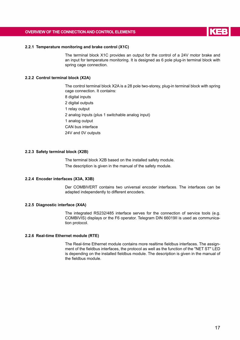
2.2.1 Temperature monitoring and brake control (X1C)
The terminal block X1C provides an output for the control of a 24V motor brake and an input for temperature monitoring. It is designed as 6 pole plug-in terminal block with spring cage connection.
2.2.2 Control terminal block (X2A)
The control terminal block X2A is a 28 pole two-storey, plug-in terminal block with spring cage connection. It contains:8 digital inputs 2 digital outputs1 relay output2 analog inputs (plus 1 switchable analog input)1 analog outputCAN bus interface 24V and 0V outputs
2.2.3 Safety terminal block (X2b)
The terminal block X2B based on the installed safety module. The description is given in the manual of the safety module.
2.2.4 encoder interfaces (X3A, X3b)
Der COMBIVERT contains two universal encoder interfaces. The interfaces can be adapted independently to different encoders.
2.2.5 Diagnostic interface (X4A)
The integrated RS232/485 interface serves for the connection of service tools (e.g. COMBIVIS) displays or the F6 operator. Telegram DIN 66019II is used as communica-tion protocol.
2.2.6 Real-time ethernet module (RTe)
TheReal-timeEthernetmodulecontainsmorerealtimefieldbusinterfaces.Theassign-mentofthefieldbusinterfaces,theprotocolaswellasthefunctionofthe"NETST"LEDisdependingontheinstalledfieldbusmodule.Thedescriptionisgiveninthemanualofthefieldbusmodule.
18
OVeRVIeW OF The CONNeCTION AND CONTROL eLeMeNTS
2.2.7 Status LeDs
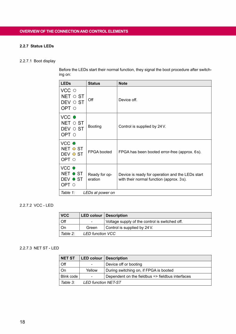
2.2.7.1 Boot display
Before the LEDs start their normal function, they signal the boot procedure after switch-ing on:
LeDs Status Note
VCCNETDEVOPT
STST Off Device off.
VCCNETDEVOPT
STST Booting Control is supplied by 24 V.
VCCNETDEVOPT
STST FPGA booted FPGA has been booted error-free (approx. 6 s).
VCCNETDEVOPT
STST
Ready for op-eration
Device is ready for operation and the LEDs start with their normal function (approx. 3 s).
Table 1: LEDs at power on
2.2.7.2 VCC - LED
VCC LeD colour DescriptionOff - Voltage supply of the control is switched off.On Green Control is supplied by 24 V.Table 2: LED function VCC
2.2.7.3 NET ST - LED
NeT ST LeD colour DescriptionOff - Device off or bootingOn Yellow During switching on, if FPGA is bootedBlink code - Dependentonthefieldbus=>fieldbusinterfacesTable 3: LED function NET-ST
19
CONNeCTION OF The CONTROL
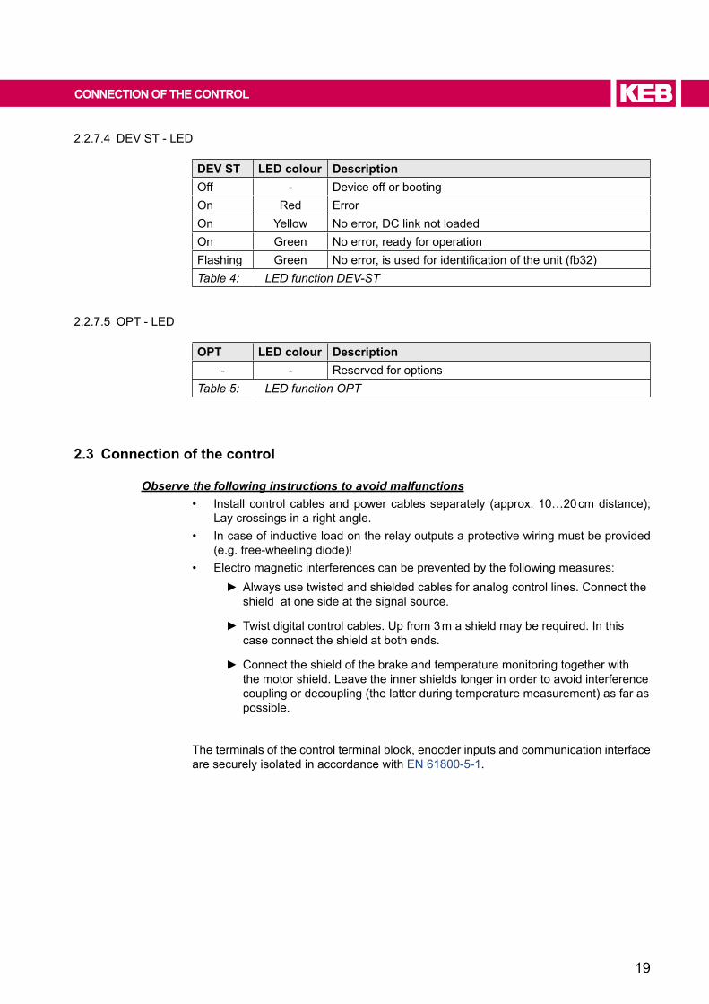
2.2.7.4 DEV ST - LED
DeV ST LeD colour DescriptionOff - Device off or bootingOn Red ErrorOn Yellow No error, DC link not loadedOn Green No error, ready for operationFlashing Green Noerror,isusedforidentificationoftheunit(fb32)Table 4: LED function DEV-ST
2.2.7.5 OPT - LED
OPT LeD colour Description- - Reserved for options
Table 5: LED function OPT
2.3 Connection of the control
Observe the following instructions to avoid malfunctions• Install controlcablesandpowercablesseparately (approx.10…20cmdistance);
Lay crossings in a right angle.• In case of inductive load on the relay outputs a protective wiring must be provided
(e.g. free-wheeling diode)!• Electro magnetic interferences can be prevented by the following measures:
Always use twisted and shielded cables for analog control lines. Connect the shield at one side at the signal source.
Twist digital control cables. Up from 3 m a shield may be required. In this case connect the shield at both ends.
Connect the shield of the brake and temperature monitoring together with the motor shield. Leave the inner shields longer in order to avoid interference coupling or decoupling (the latter during temperature measurement) as far as possible.
The terminals of the control terminal block, enocder inputs and communication interface are securely isolated in accordance with EN 61800-5-1.
20
CONNeCTION OF The CONTROL
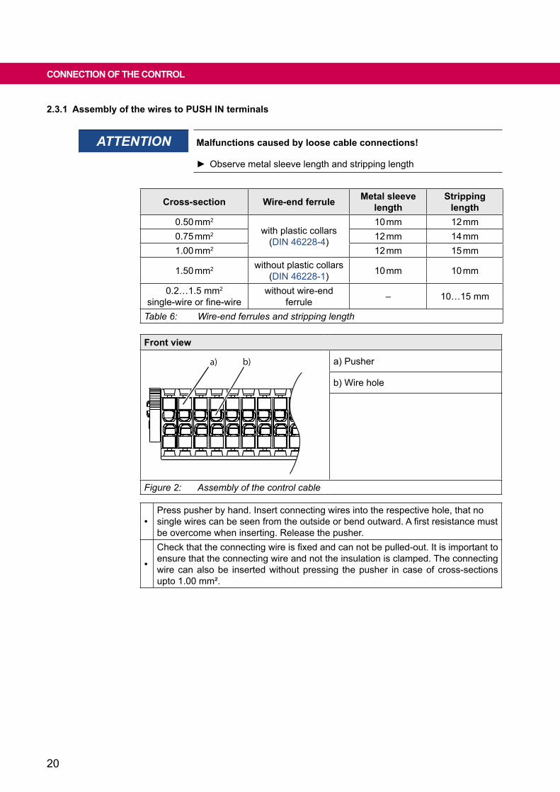
2.3.1 Assembly of the wires to PUSh IN terminals
ATTENTION Malfunctions caused by loose cable connections!
Observe metal sleeve length and stripping length
Cross-section Wire-end ferrule Metal sleeve length
Stripping length
0.50 mm2
with plastic collars(DIN 46228-4)
10 mm 12 mm0.75 mm2 12 mm 14 mm1.00 mm2 12 mm 15 mm
1.50 mm2 without plastic collars(DIN 46228-1) 10 mm 10 mm
0.2…1.5 mm2
single-wireorfine-wirewithout wire-end
ferrule – 10…15 mm
Table 6: Wire-end ferrules and stripping length
Front view
18
a) b) a) Pusher
b) Wire hole
Figure 2: Assembly of the control cable
•Press pusher by hand. Insert connecting wires into the respective hole, that no singlewirescanbeseenfromtheoutsideorbendoutward.Afirstresistancemustbe overcome when inserting. Release the pusher.
•
Checkthattheconnectingwireisfixedandcannotbepulled-out.Itisimportanttoensure that the connecting wire and not the insulation is clamped. The connecting wire can also be inserted without pressing the pusher in case of cross-sections upto 1.00 mm².

21
ASSIGNMeNT OF The TeRMINAL STRIP X2A
2.4 Assignment of the terminal strip X2A
1
2
3
4
5
6
7
8
9
10
11
12
13
14
15
16
17
18
19
20
21
22
23
24
25
26
27
28
PIN Name Description1 DI1 / AN3 Digital input 1 / analog input 3 (switchable via software)2 DI2 Digital input 23 DI3 Digital input 34 DI4 Digital input 45 DI5 Digital input 56 DI6 Digital input 67 DI7 Digital input 78 DI8 Digital input 89 0V Reference potential for digital output
10 DO1 Digital output 111 0V Reference potential for digital output12 DO2 Digital output 213 RLB Relay output / NC contact14 RLA Relay output / NO contact15 RLC Relay output/ switching contact16 24Vout DC voltage output 24 V (SELV) for input control
17 AN1-non-isolated difference input 1
18 AN1+
19 AN2-non-isolated difference input 2
20 AN2+
21 0V Reference potential for analog in-/ outputs
22 ANOUT Analog output23 CAN low
CAN bus ISO high speed according to ISO/DIN 11896 => Fieldbus interfaces24 CAN high25 CAN GND CAN ground potential-free => Fieldbus interfaces26 24Vout DC voltage output 24 V (SELV) for input control27 0V Reference potential for P24V_IN28 P24V_IN DC voltage supply 24 V
Figure 3: Assignment of the terminal strip X2A
22
ASSIGNMeNT OF The TeRMINAL STRIP X2A
2.4.1 Voltage outputs of the control terminal block
Name 24VoutFunction Voltage output (SELV) for input control
Output voltage minimum P24V_IN - 3 Vmaximum P24V_IN
permissible total current 100 mA for all 24Vout outputs together(short-circuit proof)
Table 7: Voltage output of the control
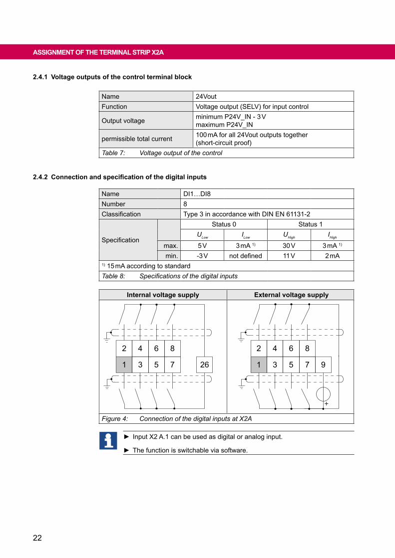
2.4.2 Connection and specification of the digital inputs
Name DI1…DI8Number 8Classification Type 3 in accordance with DIN EN 61131-2
Specification
Status 0 Status 1ULow ILow UHigh IHigh
max. 5 V 3 mA 1) 30 V 3 mA 1)
min. -3 V notdefined 11 V 2 mA1) 15 mA according to standardTable 8: Specifications of the digital inputs
Internal voltage supply external voltage supply
4 6 8
3
2
1 5 7 26
4 6 8
3
2
1 5 7 9
+
Figure 4: Connection of the digital inputs at X2A
Input X2 A.1 can be used as digital or analog input.
The function is switchable via software.

23
ASSIGNMeNT OF The TeRMINAL STRIP X2A
2.4.3 Connection and specification of the digital outputs
Name DO1…DO2Number 2Type 24 V high-side switchClassification in accordance with DIN EN 61131-2
Output voltage minimum P24V_IN - 3 Vmaximum P24V_IN
permissible output current 100 mA per output (short-circuit proof)
Others onlyohmicload;no internal free-wheeling path
Table 9: Specifications of the digital outputs
Connection appliance Connection to an external control
11
12
9
10
119
10 12
COMDI1DI2ext.
Figure 5: Examples for the connection of the digital outputs at X2A
2.4.4 Connection and specification of the relay output
Name R1Number 1maximum DC voltage 30 Vminimum current 0,01 Amaximum current 1 A
maximum number of switching cycles 108mechanically;500,000 at 1 A and 30 V
Others onlyohmicload;no internal free-wheeling path
Table 10: Specifications of the relay output
24
ASSIGNMeNT OF The TeRMINAL STRIP X2A
14
13 15
R1
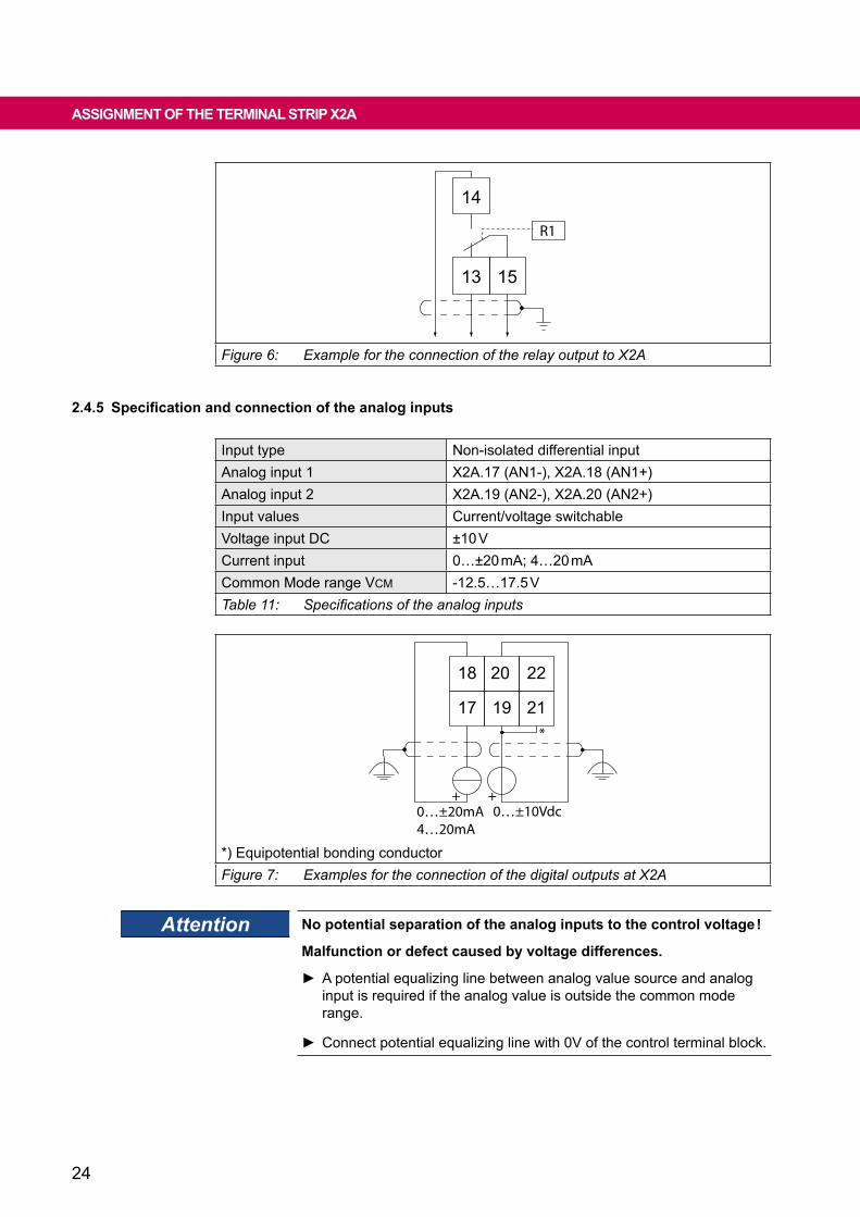
Figure 6: Example for the connection of the relay output to X2A
2.4.5 Specification and connection of the analog inputs
Input type Non-isolated differential inputAnalog input 1 X2A.17 (AN1-), X2A.18 (AN1+)Analog input 2 X2A.19 (AN2-), X2A.20 (AN2+)Input values Current/voltage switchableVoltage input DC ±10 VCurrent input 0…±20mA;4…20mACommon Mode range VCM -12.5…17.5 VTable 11: Specifications of the analog inputs
20 22
19
18
17 21
+
*
0…±10Vdc+
0…±20mA4…20mA
*) Equipotential bonding conductorFigure 7: Examples for the connection of the digital outputs at X2A
Attention No potential separation of the analog inputs to the control voltage !
Malfunction or defect caused by voltage differences.
A potential equalizing line between analog value source and analog input is required if the analog value is outside the common mode range.
Connect potential equalizing line with 0V of the control terminal block.

25
ASSIGNMeNT OF The TeRMINAL STRIP X2A
Input X2 A.1 can be used as digital or analog input.
The function is switchable via software.
RESTRICTION The analog input is not intended for the control with a potentiometer. The analog voltage must be able to supply the input current.
Input type non-isolated absolute inputAnalog input 3 X2A.1 (AN3+), X2A.9 (0V)Voltage input DC 0.2…10 V / max. 3 mATable 12: Specification of the analog input 3
2.4.6 Specification and connection of the analog output
Analog output Terminal X2A.220V reference voltage for analog output Terminal X2A.21DC voltage output 0.0…10 V (≙ 1…100 % output value)maximum current 10 mAClassificationaccordingto IEC 61131-2Table 13: Specifications of the analog output
21
22 UDC=0,0…10 VZmin=1 kΩ
Figure 8: Example for the connection of the analog output to X2A
2.4.7 Voltage input for supply of the control board and the brake
The COMBIVERT is supplied via terminals X2A.27 and X2A.28.
27
28
0V
P24Vin
X2A
PIN Name Notes
X2A.27 0V Reference potential for P24V_IN
X2A.28 P24V_IN
VoltageinputDC+24V;max.4.5 ATolerance ±5 %2 A therefrom for the control of an external brake
Figure 9: Voltage input of the control
26
TeRMINAL bLOCk X2b
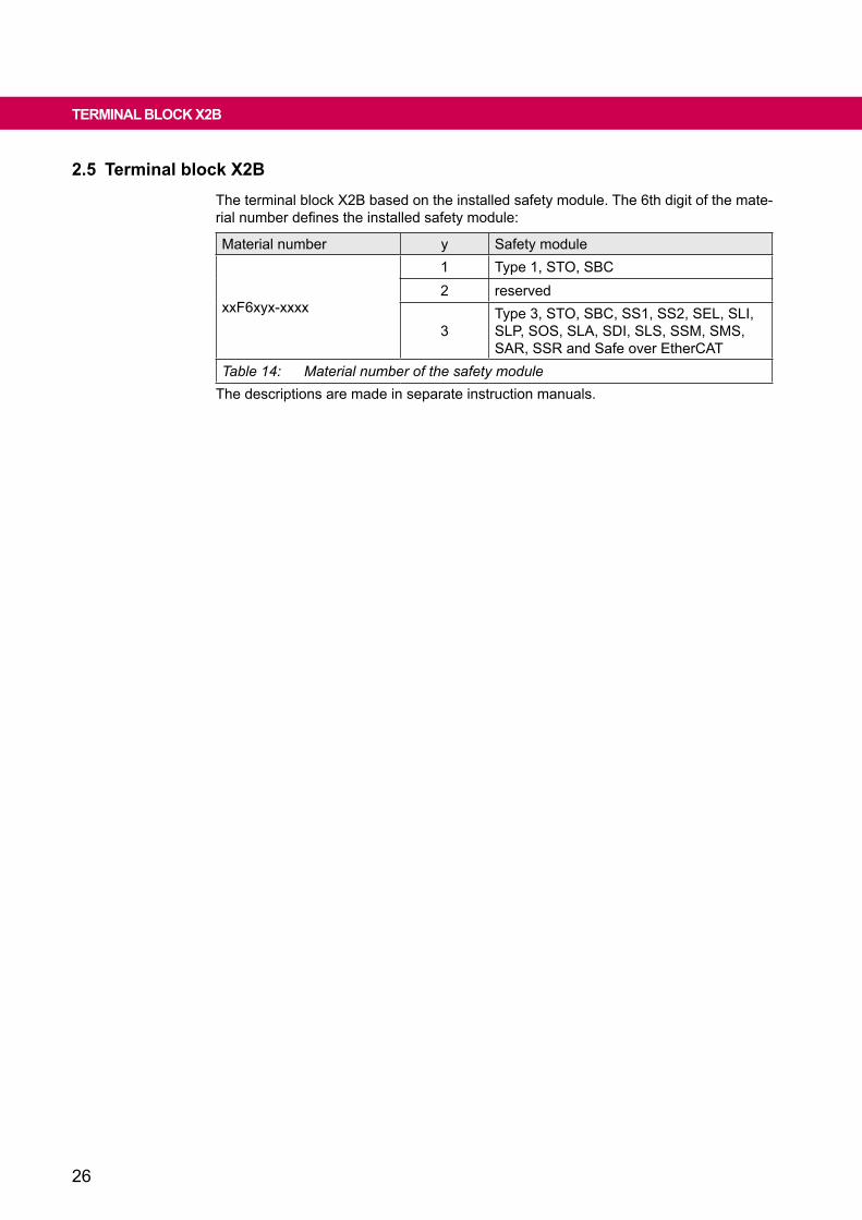
2.5 Terminal block X2bThe terminal block X2B based on the installed safety module. The 6th digit of the mate-rialnumberdefinestheinstalledsafetymodule:
Material number y Safety module
xxF6xyx-xxxx
1 Type 1, STO, SBC2 reserved
3Type 3, STO, SBC, SS1, SS2, SEL, SLI, SLP, SOS, SLA, SDI, SLS, SSM, SMS, SAR, SSR and Safe over EtherCAT
Table 14: Material number of the safety moduleThe descriptions are made in separate instruction manuals.

27
ENCODER INTERFACE
2.6 Diagnosis/visualisationThe integrated serial interface provides the following functions:• Parameterization of the unit with the KEB software COMBIVIS• Connection of a control operator• DIN66019II is used as communication protocol.
Interface SpecificationRS485 Common-mode voltage range 0…12 VRS232 ANSI TIA/EIA-232Table 15: Serial interfaces
Name Connecting cableRS232 PC inverter (SubD-9 coupling - SubD-9 plug) 0058025-001DRS232/USB (USB serial converter inclusive cable) 0058060-0040Table 16: Connecting cable
Attention No potential separation of the diagnostic interface to the control voltage !
Malfunction or defect caused by voltage differences.
Voltage differences > common-mode signal require potential equali-zation line.
AcurrentXMLfileisrequiredfortheoperationwithCOMBIVIS6.Thedownloadcan be done directly from COMBIVIS 6 while an Internet connection is present.
2.6.1 Assignment of the interface X4A
54
32
1
98
76
54
32
1
98
76
Reserved 1 6 ReservedTxD (RS232) 2 7 DGND (reference potential)RxD (RS232) 3 8 TxD-A (RS485)
RxD-A (RS485) 4 9 TxD-B (RS485)RxD-B (RS485) 5
Figure 10: PIN assignment of the serial interface X4A
28
ENCODER INTERFACE
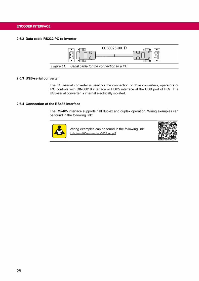
2.6.2 Data cable RS232 PC to inverter
0058025-001D1
5
6
9 1
5
6
9
Figure 11: Serial cable for the connection to a PC
2.6.3 USb-serial converter
The USB-serial converter is used for the connection of drive converters, operators or IPC controls with DIN66019 interface or HSP5 interface at the USB port of PCs. The USB-serial converter is internal electrically isolated.
2.6.4 Connection of the RS485 interface
The RS-485 interface supports half duplex and duplex operation. Wiring examples can be found in the following link:
Wiring examples can be found in the following link:ti_dr_tn-rs485-connection-0002_en.pdf

29
FIeLDbUS INTeRFACeS
2.7.1 CAN
2.7.1.1 ConnectionandspecificationoftheCANbus
X2A.23
X2A.24
X2A.25
CAN_L
CAN_H
CAN_GND
CAN_L
CAN_H
CAN_GND
COMBIVERTCANNode x
CANNode x
120Ω 120Ω
Terminal strip X2A Name Notes23 CAN low
no internally bus termination24 CAN high
25 CAN GND potential-free CAN ground (can be wired de-pending on the client)
Figure 12: Connection CAN bus to terminal block X2A
Transmission level inaccordancewithDINISO11898;ISOHighSpeed
Transmission speed 20, 25, 50, 100, 125, 250, 500, 1000 kbit/s ad-justable via (fb66: CAN baud)
Potential separation No safe isolation between CAN potential and control potential according to VDE 0160.
Bus termination 124Ωexternalbetween(CAN-HandCAN-L)atboth ends of the bus cable.
Table 17: Specifications of the CAN bus
2.7 Fieldbus interfacesThe 9th digit of the material number displays if, in addition to the CAN bus, a real-time Ethernet bus module (RTE) is installed.
Material number y Multifieldbusmodule
xxF6xxx-xyxx0 without1 with
Theactivefieldbusinterfaceisdefinedwithfb68.Themeaningofthelightpatternofthestatus LED "NET ST" changes accordingly.
Instructions for use for the real time ethernet moduel:ma_dr_rte-inst-20148981_en.pdf
30
FIeLDbUS INTeRFACeS
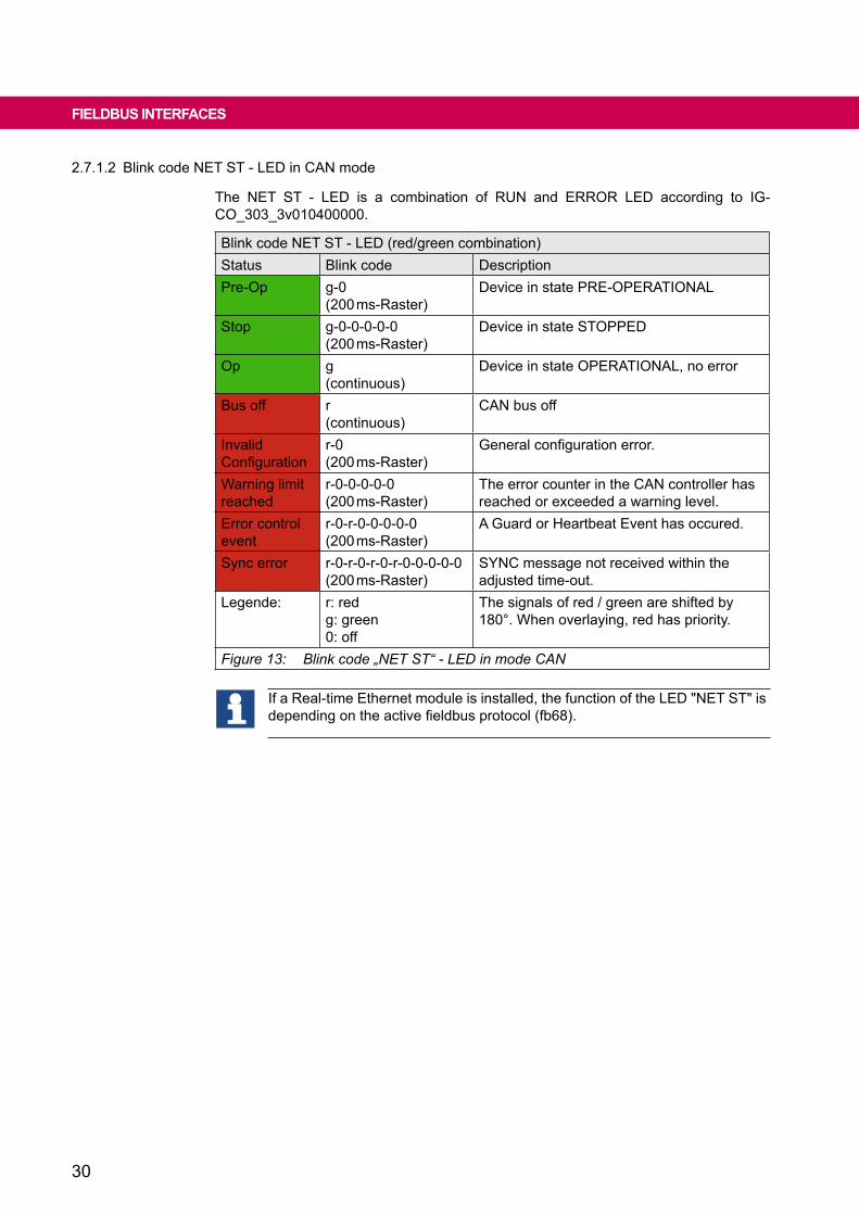
2.7.1.2 Blink code NET ST - LED in CAN mode
The NET ST - LED is a combination of RUN and ERROR LED according to IG-CO_303_3v010400000.
Blink code NET ST - LED (red/green combination)Status Blink code DescriptionPre-Op g-0
(200 ms-Raster)Device in state PRE-OPERATIONAL
Stop g-0-0-0-0-0(200 ms-Raster)
Device in state STOPPED
Op g(continuous)
Device in state OPERATIONAL, no error
Bus off r(continuous)
CAN bus off
Invalid Configuration
r-0(200 ms-Raster)
Generalconfigurationerror.
Warning limit reached
r-0-0-0-0-0(200 ms-Raster)
The error counter in the CAN controller has reached or exceeded a warning level.
Error control event
r-0-r-0-0-0-0-0(200 ms-Raster)
A Guard or Heartbeat Event has occured.
Sync error r-0-r-0-r-0-r-0-0-0-0-0(200 ms-Raster)
SYNC message not received within the adjusted time-out.
Legende: r: redg: green0: off
The signals of red / green are shifted by 180°. When overlaying, red has priority.
Figure 13: Blink code „NET ST“ - LED in mode CAN
If a Real-time Ethernet module is installed, the function of the LED "NET ST" is dependingontheactivefieldbusprotocol(fb68).

31
2.8 encoder interfaces
2.8.1 Multi-encoder-Interface
Themultiencoderinterfaceisconfiguredindual-channeltechnique.ChannelAsupportsthe following encoder types:
• Incremental encoder (RS485) input with or without zero signal• Resolver• EnDat (digital or with 1Vss incremental signals)• BISS (digital)• Hiperface• SinCoswithorwithoutzerosignal;withorwithoutabsoluteposition(SSIor
analog 1 Vpp)• SSITable 18: Supported encoders on channel A
Channel B supports the following encoder types:
• Incremental encoder (RS485) input with or without zero signal
• Incremental encoder input (HTL)• Incremental encoder (RS485) output• SSI• BISS (digital)• EnDat (digital)Table 19: Supported encoders on channel B
RESTRICTIONWhen using a digital EnDat 2.2 encoder on channel B, the use of an analog EnDat en-coder on channel A is not possible.
2.8.1.1 Assignment of the encoder interfaces X3A and X3B
Attention Undefined states by plugging of encoder cables during operation!
Malfunctions caused by incorrect speed or position values.
Do not plug on/remove encoder cable during operation.
32
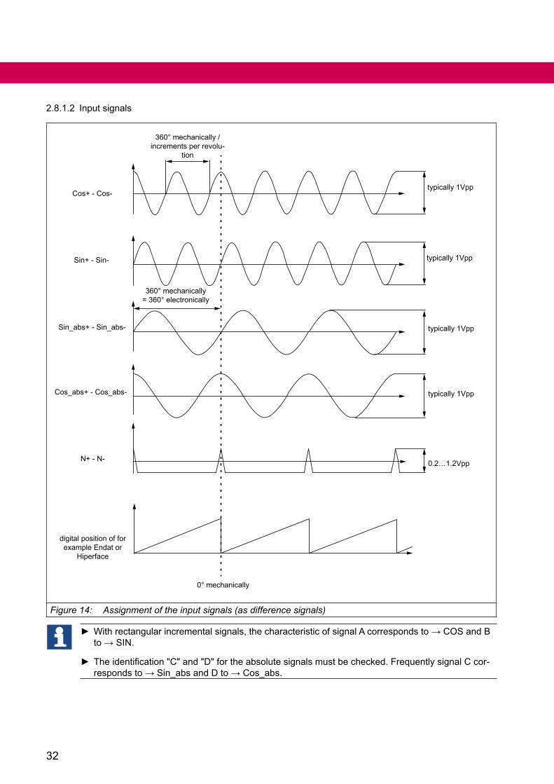
2.8.1.2 Input signals
360° mechanically /increments per revolu-
tion
360° mechanically= 360° electronically
digital position of for example Endat or
Hiperface
0° mechanically
N+ - N-
Cos_abs+ - Cos_abs-
Sin_abs+ - Sin_abs-
Sin+ - Sin-
Cos+ - Cos-typically 1Vpp
typically 1Vpp
typically 1Vpp
typically 1Vpp
0.2…1.2Vpp
Figure 14: Assignment of the input signals (as difference signals)
Withrectangularincrementalsignals,thecharacteristicofsignalAcorrespondsto→COSandBto→SIN.
Theidentification"C"and"D"fortheabsolutesignalsmustbechecked.FrequentlysignalCcor-respondsto→Sin_absandDto→Cos_abs.
33
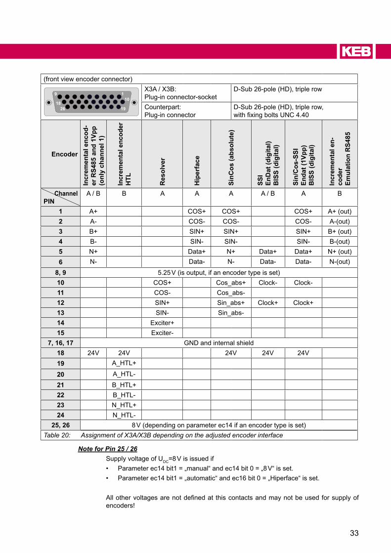
(front view encoder connector)
110
1826 19
9X3A / X3B:Plug-in connector-socket
D-Sub 26-pole (HD), triple row
Counterpart:Plug-in connector
D-Sub 26-pole (HD), triple row,withfixingboltsUNC4.40
encoder
Incr
emen
tal e
ncod
-er
RS4
85 a
nd 1
Vpp
(onl
y ch
anne
l 1)
Incr
emen
tal e
ncod
erh
TL
Res
olve
r
hip
erfa
ce
SinC
os (a
bsol
ute)
SSI
enD
at (d
igita
l)b
ISS
(dig
ital)
Sin/
Cos
-SSI
enda
t (1V
pp)
bIS
S (d
igita
l)
Incr
emen
tal e
n-co
der
emul
atio
n R
S485
ChannelPIN
A / B B A A A A / B A B
1 A+ COS+ COS+ COS+ A+ (out)2 A- COS- COS- COS- A-(out)3 B+ SIN+ SIN+ SIN+ B+ (out)4 B- SIN- SIN- SIN- B-(out)5 N+ Data+ N+ Data+ Data+ N+ (out)6 N- Data- N- Data- Data- N-(out)
8, 9 5.25 V (is output, if an encoder type is set)10 COS+ Cos_abs+ Clock- Clock-11 COS- Cos_abs-12 SIN+ Sin_abs+ Clock+ Clock+13 SIN- Sin_abs-14 Exciter+15 Exciter-
7, 16, 17 GND and internal shield18 24V 24V 24V 24V 24V19 A_HTL+
20 A_HTL-
21 B_HTL+22 B_HTL-23 N_HTL+24 N_HTL-
25, 26 8 V (depending on parameter ec14 if an encoder type is set)Table 20: Assignment of X3A/X3B depending on the adjusted encoder interface
Note for Pin 25 / 26Supply voltage of UDC=8 V is issued if• Parameter ec14 bit1 = „manual“ and ec14 bit 0 = „8 V“ is set.• Parameter ec14 bit1 = „automatic“ and ec16 bit 0 = „Hiperface“ is set.
Allothervoltagesarenotdefinedat thiscontactsandmaynotbeusedforsupplyofencoders!

34
2.8.1.3 Description of the encoder interfaces
PIN Signals
1, 2, 3, 4
A+/-, B+/-,
Cos+/-Sin+/-
Only channel A:Input for two sine-wave, shifted by 90° differential signals with UPP=1 V, maxi-mum 200 kHz.single-ended (e.g. Cos+ against GND): Constant component 2.5 V ±0.5 V
Differential (e.g. Cos+ against Cos-): Constant component 0 V ±0.1 VSignal level UPP=0.6 V…1.2 V
Channel A and b:Input for square-wave incremental signals according to RS485 maximum 300 kHz
Only channel b:Incremental encoder simulation: Position changes of channel A are output to channel B with two 90° shifted RS485 signals.
5, 6
N+/-
Only channel A:Input zero signal once per revolution.
Differential signal level (N+ - N-):• higher 50 mV: zero signal is active• from50mVto-50mV:undefined• lower -50 mV: zero signal is inactive
Signal length 330°…360° of the signal length of the incremental signals.
Channel A and b:Input zero signal or data RS485.Zero signal is 1-active, if signals A and B are also 1-active.
Only channel b:Output zero signal RS485. Zero signal is 1-active, if signals A and B are also 1-active.Is output, if the position on channel A is 0°.
Data+/-
10, 11, 12, 13
Sin+/-Cos+/-
Sin_abs+/- Cos_abs+/-
Only channel A:Input for sinusoidal absolute signals UPP=1 V for SinCos encoderUPP=3.8 V maximum for resolver
10, 12 Clock+/- Output for clock signal RS485
14, 15 Exciter+/-
Only channel A:Outputfieldvoltageforresolver:Ueff=2.54 V ≙ UPP=7.2V±5%;max.Ieff=30mA;10kHzCoupling factor for resolver: 0.5 ±10 %Phase shifting 0° ±5°
25, 26 5.25 V / 8 V
Output supply voltage for encoder: ec14 = 0 => 8 V +5 %/ -10 %ec14 = 1 => 5.25 V +5 %/ -10 %max. 500 mA total (250 mA per channel)
continued on the next page

35
PIN Signals
8, 9 5,25 VOutput supply voltage for encoder: 5.25 V +5 %/ -10 %max. 500 mA total (250 mA per channel)
18 24 V
Output supply voltage for encoder: Udc=24 V max. 500 mA total (250 mA per channel)• minimum P24V_IN - 3 V• maximum P24V_IN
19, 20, 21, 22, 23, 24
A_HTL+/-, B_HTL+/-,N_HTL+/-
Only channel b:Input HTL signals 10 V to 30 V maximum 150 kHz
Table 21: Encoder specifications
36
2.9 brake control and temperature detection
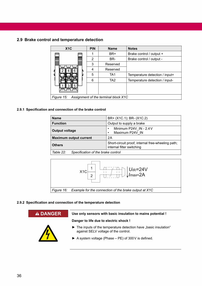
X1C PIN Name Notes
1
2
3
4
5
6
1 BR+ Brake control / output +2 BR- Brake control / output -3 Reserved4 Reserved5 TA1 Temperature detection / input+6 TA2 Temperature detection / input-
Figure 15: Assignment of the terminal block X1C
2.9.1 Specification and connection of the brake control
Name BR+(X1C.1);BR-(X1C.2)Function Output to supply a brake
Output voltage • Minimum P24V_IN - 2.4 V• Maximum P24V_IN
Maximum output current 2 A
Others Short-circuitproof,internalfree-wheelingpath;internalfilterswitching
Table 22: Specification of the brake control
2
1
Imax=2AUdc=24VX1C
Figure 16: Example for the connection of the brake output at X1C
2.9.2 Specification and connection of the temperature detection
DANGeR Use only sensors with basic insulation to mains potential !
Danger to life due to electric shock !
The inputs of the temperature detection have „basic insulation“ against SELV voltage of the control.
Asystemvoltage(Phase–PE)of300Visdefined.
37
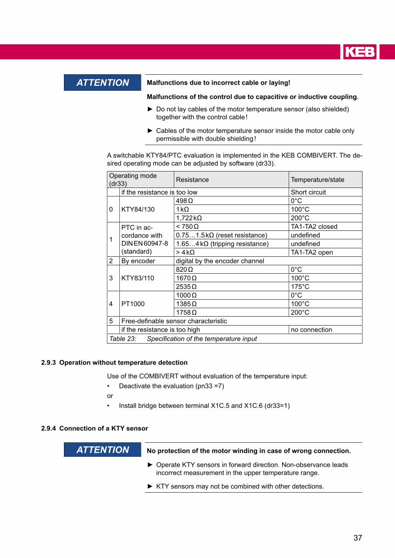
ATTENTION Malfunctions due to incorrect cable or laying!
Malfunctions of the control due to capacitive or inductive coupling.
Do not lay cables of the motor temperature sensor (also shielded) together with the control cable !
Cables of the motor temperature sensor inside the motor cable only permissible with double shielding !
A switchable KTY84/PTC evaluation is implemented in the KEB COMBIVERT. The de-sired operating mode can be adjusted by software (dr33).
Operating mode (dr33) Resistance Temperature/state
if the resistance is too low Short circuit
0 KTY84/130498Ω 0°C1kΩ 100°C1,722kΩ 200°C
1
PTC in ac-cordance with DIN EN 60947-8(standard)
<750Ω TA1-TA2 closed0.75…1.5kΩ(resetresistance) undefined1.65…4kΩ(trippingresistance) undefined>4kΩ TA1-TA2 open
2 By encoder digital by the encoder channel
3 KTY83/110820Ω 0°C1670Ω 100°C2535Ω 175°C
4 PT10001000Ω 0°C1385Ω 100°C1758Ω 200°C
5 Free-definablesensorcharacteristicif the resistance is too high no connection
Table 23: Specification of the temperature input
2.9.3 Operation without temperature detection
Use of the COMBIVERT without evaluation of the temperature input:• Deactivate the evaluation (pn33 =7)or• Install bridge between terminal X1C.5 and X1C.6 (dr33=1)
2.9.4 Connection of a kTy sensor
ATTENTION No protection of the motor winding in case of wrong connection.
Operate KTY sensors in forward direction. Non-observance leads incorrect measurement in the upper temperature range.
KTY sensors may not be combined with other detections.
38
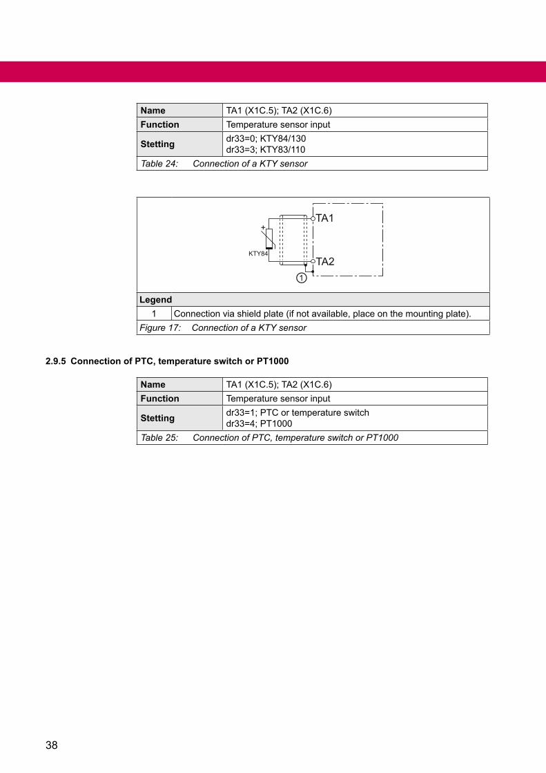
Name TA1(X1C.5);TA2(X1C.6)Function Temperature sensor input
Stetting dr33=0;KTY84/130dr33=3;KTY83/110
Table 24: Connection of a KTY sensor
TA1
TA2
+
KTY84
①Legend
1 Connection via shield plate (if not available, place on the mounting plate).Figure 17: Connection of a KTY sensor
2.9.5 Connection of PTC, temperature switch or PT1000
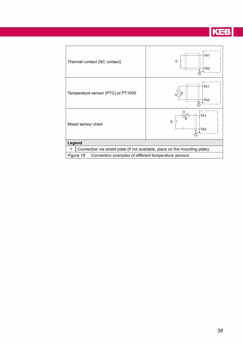
Name TA1(X1C.5);TA2(X1C.6)Function Temperature sensor input
Stetting dr33=1;PTCortemperatureswitchdr33=4;PT1000
Table 25: Connection of PTC, temperature switch or PT1000
39
Thermal contact (NC contact)TA1
TA2①
Temperature sensor (PTC) or PT1000TA1
TA2①
Mixed sensor chain
TA1
TA2①
Legend1 Connection via shield plate (if not available, place on the mounting plate).
Figure 18: Connection examples of different temperature sensors

40
ChANGe hISTORy
3 Change historyVersion Date Description
00 2016-10 Pre-serie01 2017-02 Series version02 2017-07 Insertconnectorsets;brakecontrolupdated03 2017-09 Designation of the terminals in chapter 2.4.7 corrected. New
specificationoftheanalogoutputinserted.04 2019-07 Input terminals adapted for universal use. Editorial changes.

Austria | KEB Automation GmbHRitzstraße 8 4614 Marchtrenk AustriaTel: +43 7243 53586-0 Fax: +43 7243 53586-21E-Mail: [email protected] Internet: www.keb.at
belgium | KEB Automation KGHerenveld 2 9500 Geraardsbergen BelgiumTel: +32 544 37860 Fax: +32 544 37898E-Mail: [email protected] Internet: www.keb.de
brazil | KEB South America - Regional ManagerRua Dr. Omar Pacheco Souza Riberio, 70 CEP 13569-430 Portal do Sol, São Carlos BrazilTel: +55 16 31161294 E-Mail: [email protected]
France | Société Française KEB SASUZ.I. de la Croix St. Nicolas 14, rue Gustave Eiffel94510 La Queue en Brie FranceTel: +33 149620101 Fax: +33 145767495E-Mail: [email protected] Internet: www.keb.fr
Germany | headquartersKEB Automation KGSüdstraße 38 32683 Barntrup GermanyTelefon +49 5263 401-0 Telefax +49 5263 401-116Internet: www.keb.de E-Mail: [email protected]
Germany | Geared MotorsKEB Antriebstechnik GmbHWildbacher Straße 5 08289 Schneeberg GermanyTelefon +49 3772 67-0 Telefax +49 3772 67-281Internet: www.keb-drive.de E-Mail: [email protected]
Italia | KEB Italia S.r.l. UnipersonaleVia Newton, 2 20019 Settimo Milanese (Milano) ItaliaTel: +39 02 3353531 Fax: +39 02 33500790E-Mail: [email protected] Internet: www.keb.it
Japan | KEB Japan Ltd. 15 - 16, 2 - Chome, Takanawa Minato-ku Tokyo 108 - 0074 JapanTel: +81 33 445-8515 Fax: +81 33 445-8215E-Mail: [email protected] Internet: www.keb.jp
MORE KEB PARTNERS WORLDWIDE:
... www.keb.de/de/contact/contact-worldwide
P. R. China | KEB Power Transmission Technology (Shanghai) Co. Ltd.No. 435 QianPu Road Chedun Town Songjiang District201611 Shanghai P.R. ChinaTel: +86 21 37746688 Fax: +86 21 37746600E-Mail: [email protected] Internet: www.keb.cn
Republic of korea | KEB Automation KGRoom 1709, 415 Missy 2000 725 Su Seo DongGangnam Gu 135- 757 Seoul Republic of KoreaTel: +82 2 6253 6771 Fax: +82 2 6253 6770 E-Mail: [email protected]
Russian Federation | KEB RUS Ltd.Lesnaya str, house 30 Dzerzhinsky MO140091 Moscow region Russian FederationTel: +7 495 6320217 Fax: +7 495 6320217E-Mail: [email protected] Internet: www.keb.ru
Spain | KEB Automation KGc / Mitjer, Nave 8 - Pol. Ind. LA MASIA08798 Sant Cugat Sesgarrigues (Barcelona) SpainTel: +34 93 8970268 Fax: +34 93 8992035 E-Mail: [email protected]
Switzerland | KEB Automation AGWitzbergstrasse 24 8330 Pfaeffikon/ZH SwitzerlandTel: +41 43 2886060 Fax: +41 43 2886088E-Mail: [email protected] Internet: www.keb.ch
Great britain | KEB (UK) Ltd. 5 Morris Close Park Farm Indusrial EstateWellingborough, Northants, NN8 6 XF United KingdomTel: +44 1933 402220 Fax: +44 1933 400724E-Mail: [email protected] Internet: www.keb.co.uk
United States | KEB America, Inc5100 Valley Industrial Blvd. South Shakopee, MN 55379 United StatesTel: +1 952 2241400 Fax: +1 952 2241499E-Mail: [email protected] Internet: www.kebamerica.com

Automation with Drive www.keb.deKEB Automation KG Suedstrasse 38 32683 Barntrup Tel. +49 5263 401-0 E-Mail: [email protected]


