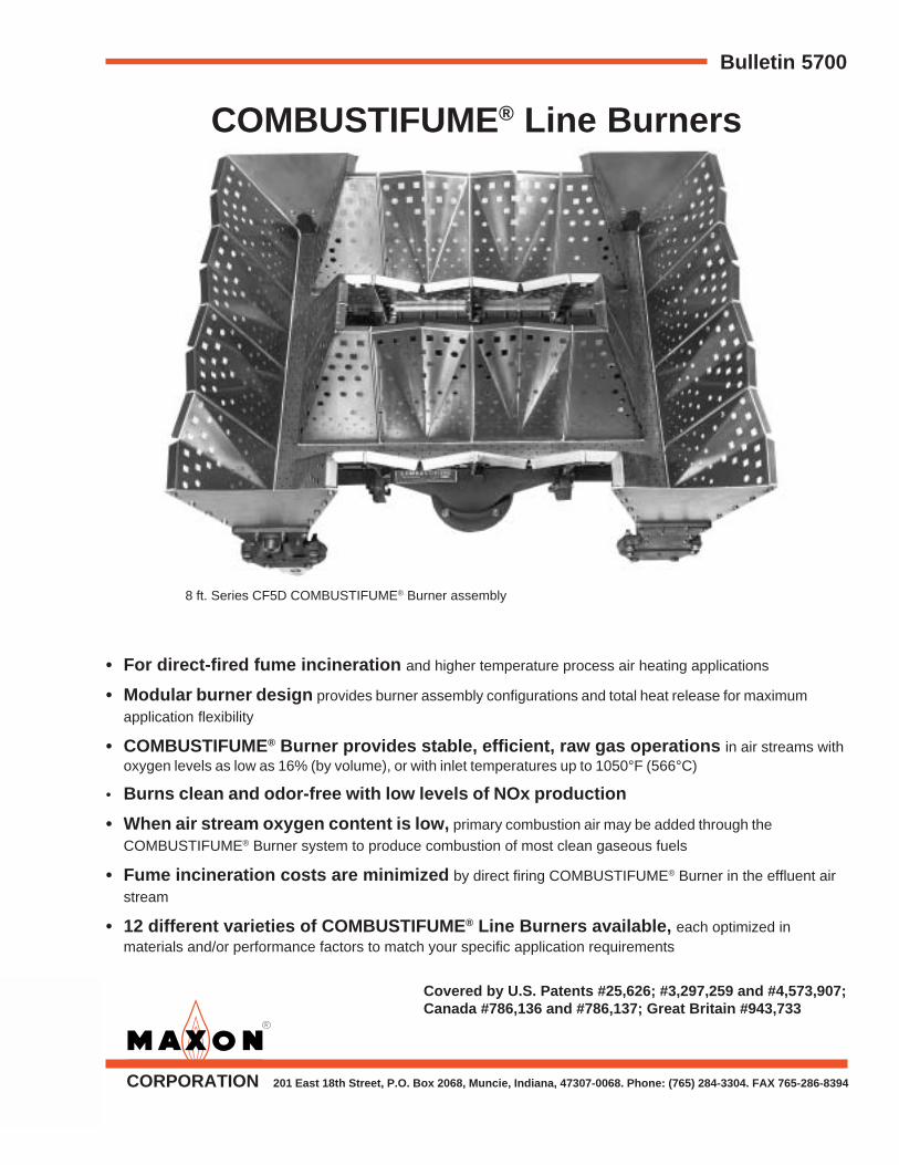
Bulletin 5700 CORPORATION 201 East 18th Street, P.O. Box 2068, Muncie, Indiana, 47307-0068. Phone: (765) 284-3304. FAX 765-286-8394 COMBUSTIFUME ® Line Burners • For direct-fired fume incineration and higher temperature process air heating applications • Modular burner design provides burner assembly configurations and total heat release for maximum application flexibility • COMBUSTIFUME ® Burner provides stable, efficient, raw gas operations in air streams with oxygen levels as low as 16% (by volume), or with inlet temperatures up to 1050°F (566°C) • Burns clean and odor-free with low levels of NOx production • When air stream oxygen content is low, primary combustion air may be added through the COMBUSTIFUME ® Burner system to produce combustion of most clean gaseous fuels • Fume incineration costs are minimized by direct firing COMBUSTIFUME ® Burner in the effluent air stream • 12 different varieties of COMBUSTIFUME ® Line Burners available, each optimized in materials and/or performance factors to match your specific application requirements Covered by U.S. Patents #25,626; #3,297,259 and #4,573,907; Canada #786,136 and #786,137; Great Britain #943,733 8 ft. Series CF5D COMBUSTIFUME ® Burner assembly
• For direct-fired fume incineration and higher temperature process air heating applications
• Modular burner design provides burner assembly configurations and total heat release for maximumapplication flexibility
• COMBUSTIFUME® Burner provides stable, efficient, raw gas operations in air streams withoxygen levels as low as 16% (by volume), or with inlet temperatures up to 1050°F (566°C)
• Burns clean and odor-free with low levels of NOx production
• When air stream oxygen content is low, primary combustion air may be added through theCOMBUSTIFUME® Burner system to produce combustion of most clean gaseous fuels
• Fume incineration costs are minimized by direct firing COMBUSTIFUME® Burner in the effluent airstream
• 12 different varieties of COMBUSTIFUME® Line Burners available, each optimized inmaterials and/or performance factors to match your specific application requirements
Covered by U.S. Patents #25,626; #3,297,259 and #4,573,907;Canada #786,136 and #786,137; Great Britain #943,733
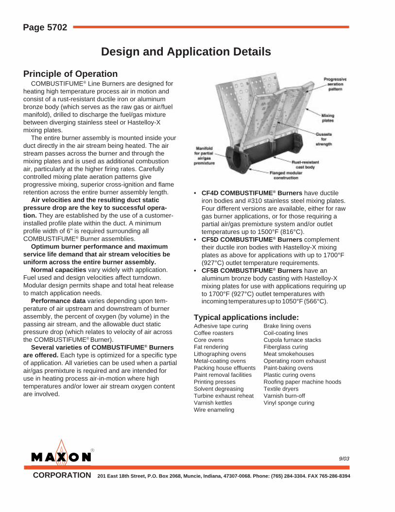
Principle of OperationCOMBUSTIFUME® Line Burners are designed for
heating high temperature process air in motion andconsist of a rust-resistant ductile iron or aluminumbronze body (which serves as the raw gas or air/fuelmanifold), drilled to discharge the fuel/gas mixturebetween diverging stainless steel or Hastelloy-Xmixing plates.
The entire burner assembly is mounted inside yourduct directly in the air stream being heated. The airstream passes across the burner and through themixing plates and is used as additional combustionair, particularly at the higher firing rates. Carefullycontrolled mixing plate aeration patterns giveprogressive mixing, superior cross-ignition and flameretention across the entire burner assembly length.
Air velocities and the resulting duct staticpressure drop are the key to successful opera-tion. They are established by the use of a customer-installed profile plate within the duct. A minimumprofile width of 6" is required surrounding allCOMBUSTIFUME® Burner assemblies.
Optimum burner performance and maximumservice life demand that air stream velocities beuniform across the entire burner assembly.
Normal capacities vary widely with application.Fuel used and design velocities affect turndown.Modular design permits shape and total heat releaseto match application needs.
Performance data varies depending upon tem-perature of air upstream and downstream of burnerassembly, the percent of oxygen (by volume) in thepassing air stream, and the allowable duct staticpressure drop (which relates to velocity of air acrossthe COMBUSTIFUME® Burner).
Several varieties of COMBUSTIFUME® Burnersare offered. Each type is optimized for a specific typeof application. All varieties can be used when a partialair/gas premixture is required and are intended foruse in heating process air-in-motion where hightemperatures and/or lower air stream oxygen contentare involved.
• CF4D COMBUSTIFUME® Burners have ductileiron bodies and #310 stainless steel mixing plates.Four different versions are available, either for rawgas burner applications, or for those requiring apartial air/gas premixture system and/or outlettemperatures up to 1500°F (816°C).
• CF5D COMBUSTIFUME® Burners complementtheir ductile iron bodies with Hastelloy-X mixingplates as above for applications with up to 1700°F(927°C) outlet temperature requirements.
• CF5B COMBUSTIFUME® Burners have analuminum bronze body casting with Hastelloy-Xmixing plates for use with applications requiring upto 1700°F (927°C) outlet temperatures withincoming temperatures up to 1050°F (566°C).
To properly select the appropriate typeCOMBUSTIFUME® Line Burner to meet your specificapplication requirements, these four factors must firstbe determined:1. Percent (by volume) of oxygen remaining in air
stream to be heated2. Allowable duct static pressure drop, which is a
direct relationship to the velocity of air across theburner and/or profile plate
3. Air stream temperatures approaching anddownstream of the COMBUSTIFUME® Burner
4. Type of fuel to be fired through the burner
Oxygen content and temperature of effluent/airstream dictates how and which COMBUSTIFUME®
Line Burner must be applied. Flammability of a rawgas burner is affected by oxygen content, air streamtemperature and moisture content. Since a typicalapplication for COMBUSTIFUME® Burners wouldinvolve an air stream temperature of 700°F or higher,air streams with measured oxygen levels above 16%(by volume) will normally support combustion by araw gas burner and not require additional primarycombustion air. However, if measured oxygen contentin air stream is less than 16% or air streamtemperature is less than 500°F, a percentage ofpartial premixed gas/air may be required tosupplement the lower oxygen levels in your systemfor a complete combustion reaction to occur. Pleaserefer to the Air Stream Flammability Chart on thispage for the exact oxygen requirements of effluent/airstreams.
Elevated air stream temperatures approachinga COMBUSTIFUME® Burner can be as high as1050°F (566°C). This naturally causes changes in airdensity and net air velocities, and results in an effecton COMBUSTIFUME® Burner performance.
The combination effect of lower inlettemperature and lower oxygen levels will normallyrequire a partial percentage of premixture be addedthrough the COMBUSTIFUME® Burner system.
This combination effect (or air stream flammability)is graphically illustrated in the chart at right.
Since oxygen content within the air stream iscritical to the flammability range of aCOMBUSTIFUME® Burner, it also directly affects themaximum capacity (Btu/hr per lineal foot) of theburner assembly.
Any combination of temperatures and oxygen levelsfalling above the raw gas firing diagonal line shouldsupport combustion with a raw gas COMBUSTIFUME®
Burner system.Any combination of incoming temperature and
measured percent of oxygen falling below thediagonal line will normally require the designatedpercentage of premixing through aCOMBUSTIFUME® Burner system.
Notice: When primary combustion air issupplemented in the system, a corresponding workload increase must be factored into the grossheating requirement to heat the fresh combustionair being introduced.
Page 5704 COMBUSTIFUME® Line Burners
Performance Selection Data
GeneralAir stream velocity and resulting pressure drop
affect performance of COMBUSTIFUME® Burnersystems. This velocity across and through yourburner’s mixing plates must be kept uniform andwithin desired limits by use of a (customer fabricated)silhouette profile plate through which the burner fires.A minimum 6" profile plate should be installedsurrounding the interior duct walls at the leading edgeof your burner’s mixing plates.
Optimum design operating velocity ranges areshown in preceding pages. The most accuratereadings for velocities (in SFPM) are as measuredwith a velometer (or pitot tube) directly in the duct atthe plane of the profile plate and leading edge of yourburner’s mixing plates.
Since COMBUSTIFUME® Burner systems areinstalled in such widely diversified applications, it isoften difficult to get into the chamber/duct and profileplate area to obtain the velocity pressure readingsdescribed above. For this reason, a closeapproximation of operating velocities may be madewith a measurement of duct static pressure drop.Preferably, a static pressure test point one ductdiameter in distance upstream from the profile plateand one duct diameter length downstream will givean approximation of operating velocity across theburner.
These static pressure drops relate to velocity(in SFPM) as shown in Table 1 below.
CAUTION: Do not try to take a differential staticpressure reading from a test port at or near an elbowin the duct or chamber due to potentially erroneousreadings caused by turbulence set up within the ductat such points. Measure in a straight duct with at leastone duct diameter in length before and after theprofile opening.
For lower temperature rise applications,determine profile opening area by adding burnerdisplacement area (ft2/section) from page 5705 to netfree area of your duct:
Fan volume (SCFM)
Velocity (SFPM)
NOTE: Various duct size/profile area relationshipsmay give slightly different field site data than is shownin static pressure chart below.
Thermal expansion due to the high operatingtemperature of incineration units requires specialcare in manifold and combustion chamber design.Flexible connections between manifold and burnerassembly inlets are recommended, and provisionshould be made in burner support to allow for growthwith temperature.
Flame supervision by UV scanner is preferred,and must be used whenever effluent inlet tempera-tures exceed 600°F (316°C). Cooling or purge air tothe scanner connection is recommended. Flame rodscan be mounted through pilot assembly, but arelimited to 600°F (316°C) effluent inlet temperature.
Observation and access are both important to asuccessful installation. Ability to view the flame fromdownstream of burner (particularly pilot location)greatly simplifies start-up and operating procedures,while access to upstream side of burner facilitateseventual maintenance.
Displacement area per sectionFor purposes of calculating operating air velocities
and resulting static pressure drops across the burnerassembly and profile plate, use the followingequivalent displacements:
Each 6" straight section: 0.35 ft2
Each 12" straight & 12B section: 0.7 ft2
Each 12" x 6" tee section: 0.75 ft2
Each 12" x 12" cross & BX section: 0.85 ft2
Each 36" B H section: 1.5 ft2
Maxon assumes no responsibility for the use or misuse ofthe piping layouts shown. Specific piping and wiringdiagrams should always be submitted to the appropriateagencies for approval on each application.
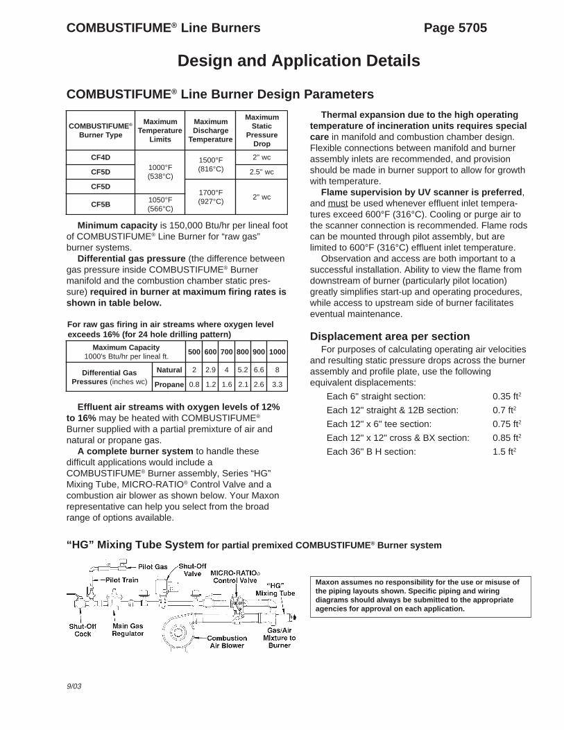
Minimum capacity is 150,000 Btu/hr per lineal footof COMBUSTIFUME® Line Burner for “raw gas”burner systems.
Differential gas pressure (the difference betweengas pressure inside COMBUSTIFUME® Burnermanifold and the combustion chamber static pres-sure) required in burner at maximum firing rates isshown in table below.
Effluent air streams with oxygen levels of 12%to 16% may be heated with COMBUSTIFUME®
Burner supplied with a partial premixture of air andnatural or propane gas.
A complete burner system to handle thesedifficult applications would include aCOMBUSTIFUME® Burner assembly, Series “HG”Mixing Tube, MICRO-RATIO® Control Valve and acombustion air blower as shown below. Your Maxonrepresentative can help you select from the broadrange of options available.
“HG” Mixing Tube System for partial premixed COMBUSTIFUME® Burner system
Series “HG” Mixing Tubes with partially premixed COMBUSTIFUME® Burnersystem in 12 – 16% oxygen level air stream applications
General Selection Procedure:1. Determine available oxygen level in
air stream to be heated.2. Enter Table 1 under column with
specific oxygen level for parametersof your application. Available oxygenlevel dictates combustion air andextra heat requirements for additionalprimary air flows.
3. Calculate gross heat requirement.4. Determine burner footage and inlet
feed requirements.5. Select “HG” Mixing Tube size from
Table 2 based upon the volume ofcombustion air required.
Example:– Required heat release of 7,000,000 Btu/hr– For system measured with 13.5% oxygen in air
stream
From Table 1 (13 to 13.9%, middle column)
A. Gross heat required7,000,000 x 1.075 = 7,525,000 Btu/hr
B. = 10.75 ft. = 11 ft. of burner
C. = 2 inlets
D. 11 ft. x 41 SCFM/ft = 451 SCFM primary air withdifferential pressure = 6.4" wc
From Table 2 (400 to 1167 SCFM)
E. Select 6" HG Mixing Tube with12 each 29/64" gas orifices per Table 3
F. Select MICRO-RATIO® Control Valve– for 451 SCFM air = (27060 SCFH)– for 7525 SCFH natural gas
Raw gas firing of COMBUSTIFUME® Burners in air streams with 16+% oxygen levels
Profiling for higher temperature applicationsWhen calculating profile dimensions for
COMBUSTIFUME® Burner systems in applicationswith higher inlet air temperatures, greater temperaturerises, and/or variable air stream volumes, the air withelevated temperatures and densities must beconsidered.
Sample CalculationsA sample procedure for designing a raw gas
COMBUSTIFUME® Burner system for a thermal fuelincinerator (with 16+% oxygen level) is providedbelow.
General Selection Procedure1. Determine available oxygen level in air stream
to be heated.For a raw gas application, we will use 16+%oxygen level.
2. Determine the SCFM of air through theincinerator. Include any variations in this flow.
For our calculations, we will use a constantvolume air fan of 5000 SCFM.
3. Determine inlet temperature of effluent toCOMBUSTIFUME® Burner.
We will use inlet temperature of 700°F.
4. Determine outlet or discharge temperaturesfrom the incinerator.
For our example, we will design for 1500°F.
5. Determine the volume of any combustiblehydrocarbons in the effluent air stream.
We will use 20 gallons of evaporated solventper hour @ 110,000 Btu/gallon.
6. Determine available gas pressure and itsanticipated pressure drop through the controlsystem’s piping and valves.
For this example, we will use 5 PSIG naturalgas supply pressure available; 3" wc pressuredrop through control system; +3" wc staticpressure in combustion chamber; 8" wcdifferential gas pressure required to burner and14" wc gas pressure required from main gasregulator (at maximum burner firing rate).
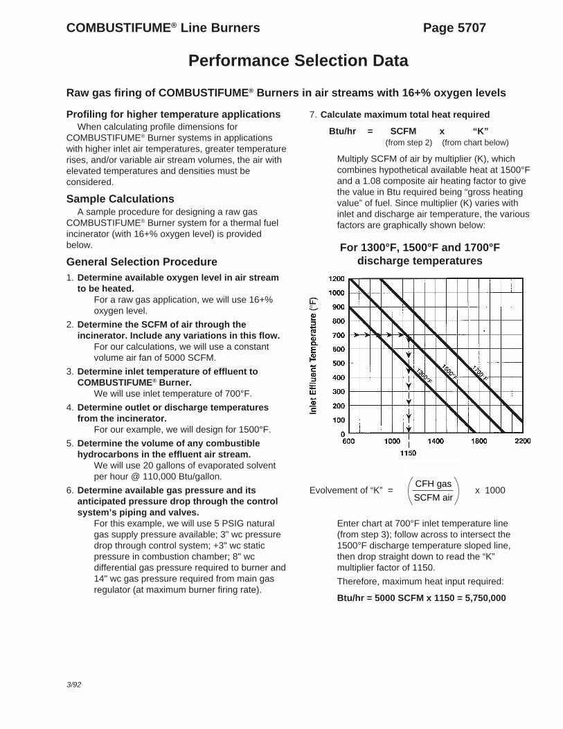
7. Calculate maximum total heat required
Btu/hr = SCFM x “K”(from step 2) (from chart below)
Multiply SCFM of air by multiplier (K), whichcombines hypothetical available heat at 1500°Fand a 1.08 composite air heating factor to givethe value in Btu required being “gross heatingvalue” of fuel. Since multiplier (K) varies withinlet and discharge air temperature, the variousfactors are graphically shown below:
For 1300°F, 1500°F and 1700°Fdischarge temperatures
Evolvement of “K” = x 1000
Enter chart at 700°F inlet temperature line(from step 3); follow across to intersect the1500°F discharge temperature sloped line,then drop straight down to read the “K”multiplier factor of 1150.
Therefore, maximum heat input required:
Btu/hr = 5000 SCFM x 1150 = 5,750,000
CFH gas
SCFM air
Page 5708 COMBUSTIFUME® Line Burners
Performance Selection Data
Design procedure and calculation example (continued)
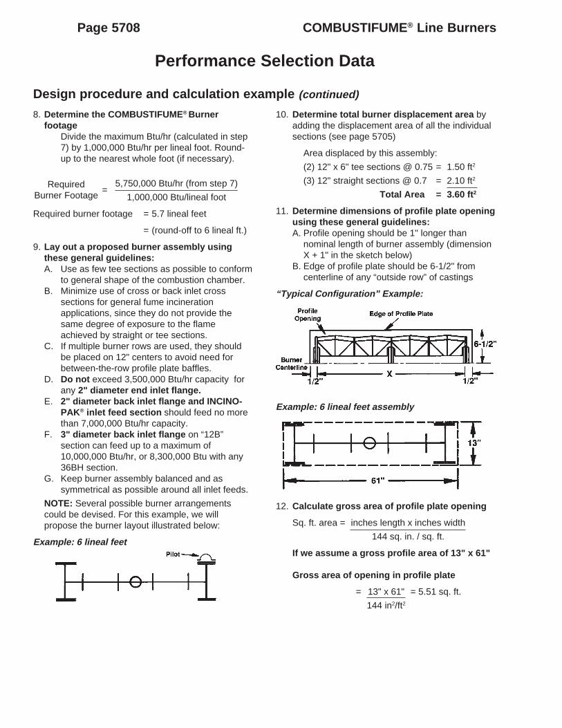
8. Determine the COMBUSTIFUME® Burnerfootage
Divide the maximum Btu/hr (calculated in step7) by 1,000,000 Btu/hr per lineal foot. Round-up to the nearest whole foot (if necessary).
5,750,000 Btu/hr (from step 7)
1,000,000 Btu/lineal foot
Required burner footage = 5.7 lineal feet
= (round-off to 6 lineal ft.)
9. Lay out a proposed burner assembly usingthese general guidelines:A. Use as few tee sections as possible to conform
to general shape of the combustion chamber.B. Minimize use of cross or back inlet cross
sections for general fume incinerationapplications, since they do not provide thesame degree of exposure to the flameachieved by straight or tee sections.
C. If multiple burner rows are used, they shouldbe placed on 12" centers to avoid need forbetween-the-row profile plate baffles.
D. Do not exceed 3,500,000 Btu/hr capacity forany 2" diameter end inlet flange.
E. 2" diameter back inlet flange and INCINO-PAK® inlet feed section should feed no morethan 7,000,000 Btu/hr capacity.
F. 3" diameter back inlet flange on “12B”section can feed up to a maximum of10,000,000 Btu/hr, or 8,300,000 Btu with any36BH section.
G. Keep burner assembly balanced and assymmetrical as possible around all inlet feeds.
NOTE: Several possible burner arrangementscould be devised. For this example, we willpropose the burner layout illustrated below:
Example: 6 lineal feet
RequiredBurner Footage
=
10. Determine total burner displacement area byadding the displacement area of all the individualsections (see page 5705)
Area displaced by this assembly:
(2) 12" x 6" tee sections @ 0.75 = 1.50 ft2
(3) 12" straight sections @ 0.7 = 2.10 ft2
Total Area = 3.60 ft2
11. Determine dimensions of profile plate openingusing these general guidelines:A. Profile opening should be 1" longer than
nominal length of burner assembly (dimensionX + 1" in the sketch below)
B. Edge of profile plate should be 6-1/2" fromcenterline of any “outside row” of castings
“Typical Configuration” Example:
Example: 6 lineal feet assembly
12. Calculate gross area of profile plate opening
Sq. ft. area = inches length x inches width
144 sq. in. / sq. ft.
If we assume a gross profile area of 13" x 61"
Gross area of opening in profile plate
= 13" x 61" = 5.51 sq. ft.
144 in2/ft2
COMBUSTIFUME® Line Burners Page 5709
Performance Selection Data
9/03
Design procedure and calculation example (continued)
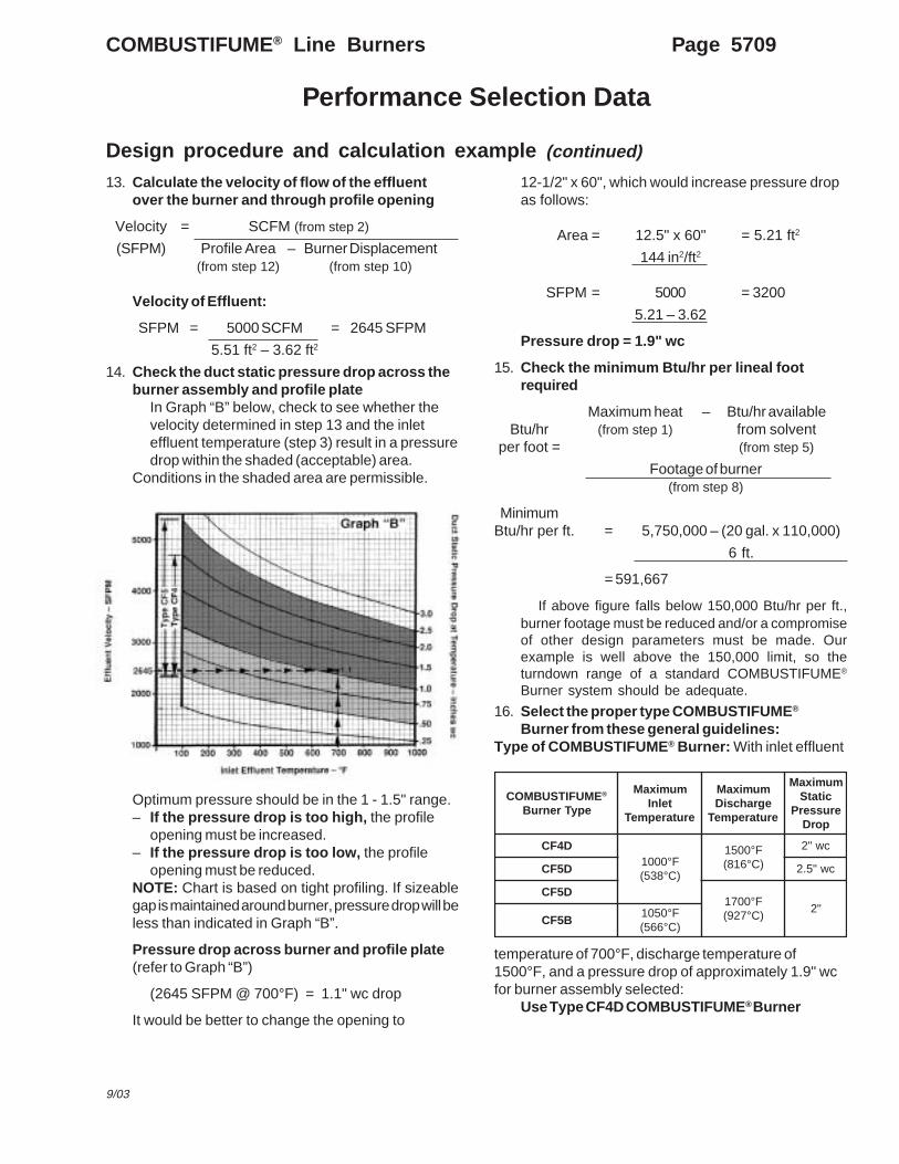
13. Calculate the velocity of flow of the effluentover the burner and through profile opening
14. Check the duct static pressure drop across theburner assembly and profile plate
In Graph “B” below, check to see whether thevelocity determined in step 13 and the inleteffluent temperature (step 3) result in a pressuredrop within the shaded (acceptable) area.
Conditions in the shaded area are permissible.
12-1/2" x 60", which would increase pressure dropas follows:
Area = 12.5" x 60" = 5.21 ft2
144 in2/ft2
SFPM = 5000 = 3200
5.21 – 3.62
Pressure drop = 1.9" wc
15. Check the minimum Btu/hr per lineal footrequired
Maximum heat – Btu/hr availableBtu/hr (from step 1) from solvent
per foot = (from step 5)
Footage of burner(from step 8)
MinimumBtu/hr per ft. = 5,750,000 – (20 gal. x 110,000)
6 ft.
= 591,667
If above figure falls below 150,000 Btu/hr per ft.,burner footage must be reduced and/or a compromiseof other design parameters must be made. Ourexample is well above the 150,000 limit, so theturndown range of a standard COMBUSTIFUME®
Burner system should be adequate.
16. Select the proper type COMBUSTIFUME®
Burner from these general guidelines:Type of COMBUSTIFUME® Burner: With inlet effluent
temperature of 700°F, discharge temperature of1500°F, and a pressure drop of approximately 1.9" wcfor burner assembly selected:
Use Type CF4D COMBUSTIFUME® Burner
Optimum pressure should be in the 1 - 1.5" range.– If the pressure drop is too high, the profile
opening must be increased.– If the pressure drop is too low, the profile
opening must be reduced.NOTE: Chart is based on tight profiling. If sizeablegap is maintained around burner, pressure drop will beless than indicated in Graph “B”.
Pressure drop across burner and profile plate(refer to Graph “B”)
(2645 SFPM @ 700°F) = 1.1" wc drop
It would be better to change the opening to
EMUFITSUBMOC ®
epyTrenruB
mumixaMtelnI
erutarepmeT
mumixaMegrahcsiD
erutarepmeT
mumixaMcitatS
erusserPporD
D4FCF°0001)C°835(
F°0051)C°618(
cw"2
D5FC cw"5.2
D5FCF°0071)C°729(
"2B5FC
F°0501)C°665(
Page 5710 COMBUSTIFUME® Line Burners
Capacity/Selection Data
Based on capacity information given in this catalogsection, and within the constraints of duct size and airvolume flows, a COMBUSTIFUME® Burner assemblyis designed utilizing these available sections shown onthe following pages.
When ordering a burner assembly made up fromthese available module components, be sure to providean assembly sketch of the complete burner (as viewedfrom the back, or upstream, side), including locationsof all accessories and/or individual componentsections.
All open ends of burner assembly must beclosed off with one of the end closures or pilotassemblies shown on the following pages. Any endplate ports not used must be plugged.
Air stream velocity and resulting static pressuredrop affect performance and are achieved by means ofa silhouette profile plate within the duct.
A minimum profile plate width of 6" is requiredsurrounding all COMBUSTIFUME® Burnerassemblies.
Burner inlet feed piping must be adequate toprovide a well-distributed flow of air/gas throughout the
burner assembly. Burner assembly layout should besymmetrical and balanced with relation to inlet feedsections.
Do not exceed the capacity feed limitations shownin the table below.
Inlet flanges bolt directly to burner body casting andaccept threaded NPT piping. Chart above showsmaximum lineal feet of COMBUSTIFUME® Burner thatmay be fed by a given inlet flange.
COMBUSTIFUME® Line Burner Designation
Example: 12" x 12" bk inlet section CF 5 – BX – D – 24
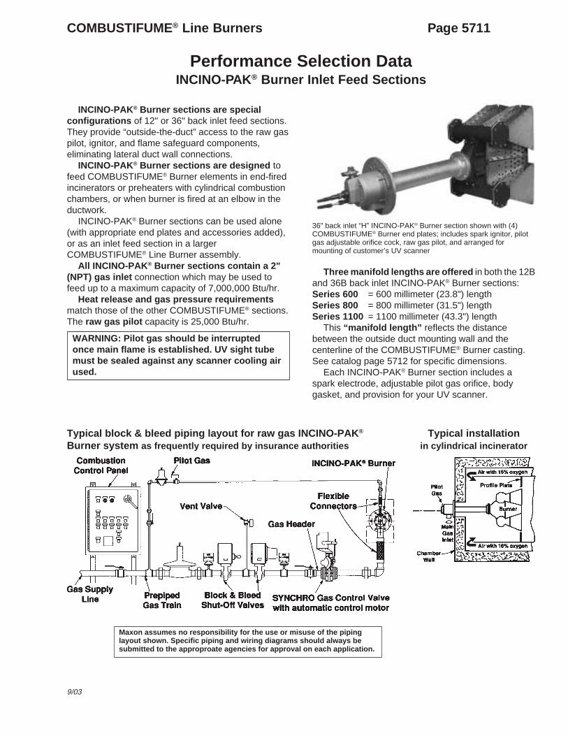
INCINO-PAK® Burner sections are specialconfigurations of 12" or 36" back inlet feed sections.They provide “outside-the-duct” access to the raw gaspilot, ignitor, and flame safeguard components,eliminating lateral duct wall connections.
INCINO-PAK® Burner sections are designed tofeed COMBUSTIFUME® Burner elements in end-firedincinerators or preheaters with cylindrical combustionchambers, or when burner is fired at an elbow in theductwork.
INCINO-PAK® Burner sections can be used alone(with appropriate end plates and accessories added),or as an inlet feed section in a largerCOMBUSTIFUME® Line Burner assembly.
All INCINO-PAK® Burner sections contain a 2"(NPT) gas inlet connection which may be used tofeed up to a maximum capacity of 7,000,000 Btu/hr.
Heat release and gas pressure requirementsmatch those of the other COMBUSTIFUME® sections.The raw gas pilot capacity is 25,000 Btu/hr.
WARNING: Pilot gas should be interruptedonce main flame is established. UV sight tubemust be sealed against any scanner cooling airused.
36" back inlet “H” INCINO-PAK® Burner section shown with (4)COMBUSTIFUME® Burner end plates; includes spark ignitor, pilotgas adjustable orifice cock, raw gas pilot, and arranged formounting of customer’s UV scanner
Three manifold lengths are offered in both the 12Band 36B back inlet INCINO-PAK® Burner sections:Series 600 = 600 millimeter (23.8") lengthSeries 800 = 800 millimeter (31.5") lengthSeries 1100 = 1100 millimeter (43.3") length
This “manifold length” reflects the distancebetween the outside duct mounting wall and thecenterline of the COMBUSTIFUME® Burner casting.See catalog page 5712 for specific dimensions.
Each INCINO-PAK® Burner section includes aspark electrode, adjustable pilot gas orifice, bodygasket, and provision for your UV scanner.
Typical block & bleed piping layout for raw gas INCINO-PAK®
Burner system as frequently required by insurance authoritiesTypical installation
in cylindrical incinerator
Maxon assumes no responsibility for the use or misuse of the pipinglayout shown. Specific piping and wiring diagrams should always besubmitted to the approproate agencies for approval on each application.
Page 5712 COMBUSTIFUME® Line Burners
Dimensions (in inches)
INCINO-PAK® Burner Back Inlet Sections
36" back inlet “H” section
12" back inlet “12B” section
Pipe threads on this page conform toNPT (ANSI Standard B2.1)
seireS A B L X
006 18.32 52.73 56.13 5.1
008 5.13 52.54 43.93 57.1
0011 13.34 52.65 51.15 1
COMBUSTIFUME® Line Burners Page 5713
9/03
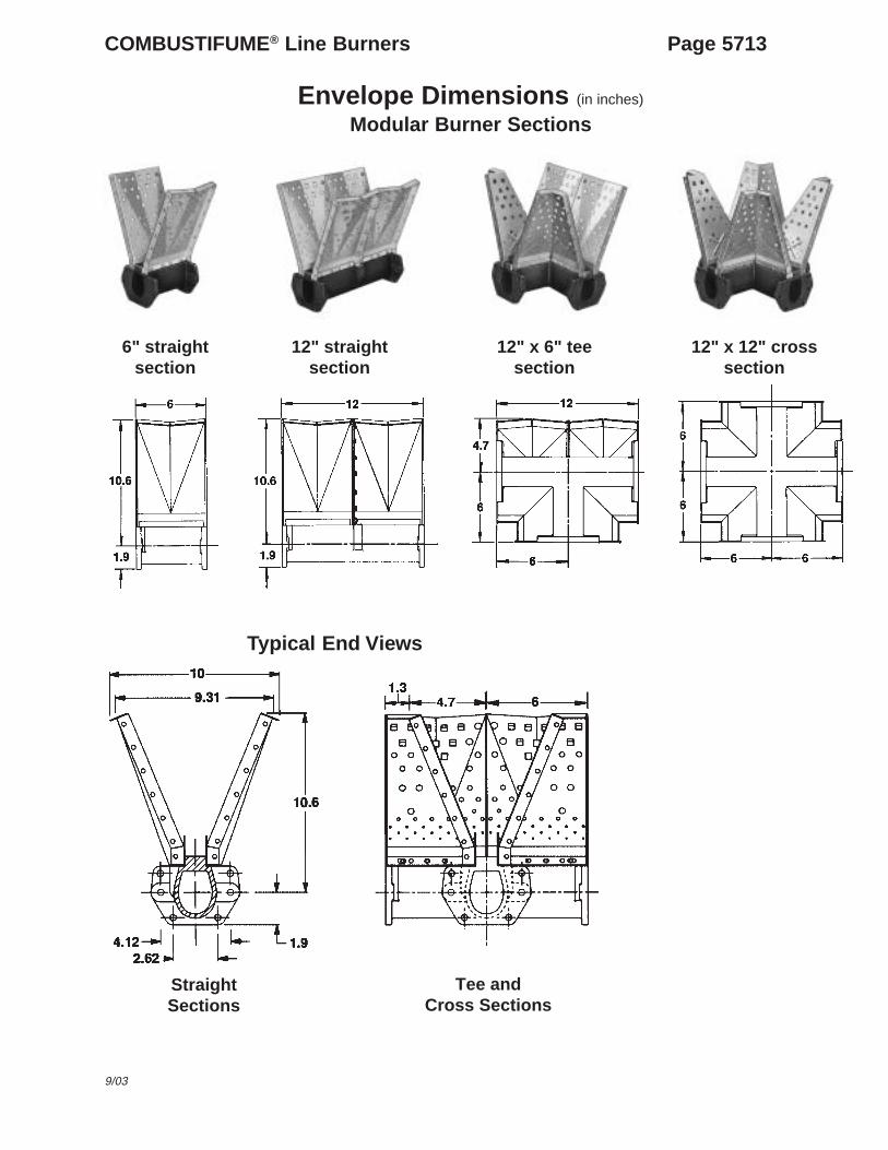
Envelope Dimensions (in inches)
Modular Burner Sections
12" x 6" teesection
12" x 12" crosssection
12" straightsection
6" straightsection
Typical End Views
Tee andCross Sections
StraightSections
Page 5714 COMBUSTIFUME® Line Burners
Envelope Dimensions (in inches)
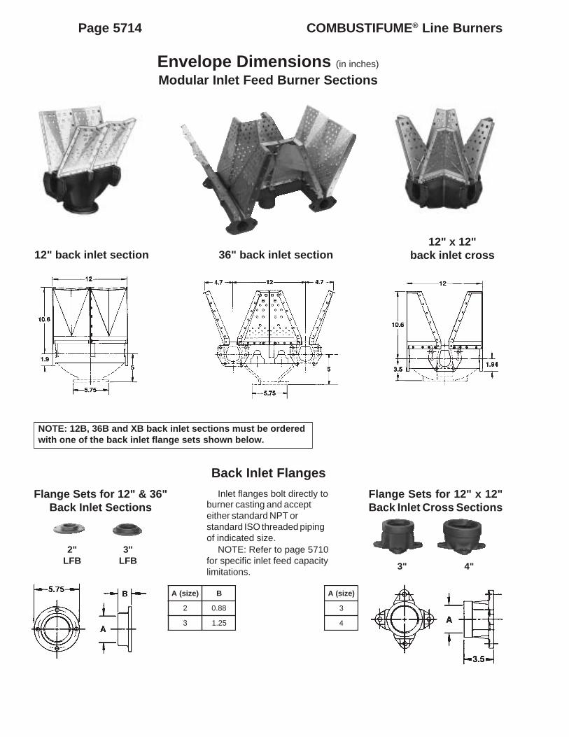
Modular Inlet Feed Burner Sections
36" back inlet section12" back inlet section12" x 12"
back inlet cross
NOTE: 12B, 36B and XB back inlet sections must be orderedwith one of the back inlet flange sets shown below.
Back Inlet Flanges
Flange Sets for 12" & 36"Back Inlet Sections
2"LFB
3"LFB
Flange Sets for 12" x 12"Back Inlet Cross Sections
3" 4"
Inlet flanges bolt directly toburner casting and accepteither standard NPT orstandard ISO threaded pipingof indicated size.
NOTE: Refer to page 5710for specific inlet feed capacitylimitations.
)ezis(A B
2 88.0
3 52.1
)ezis(A
3
4
COMBUSTIFUME® Line Burners Page 5715
9/03
Envelope Dimensions (in inches)
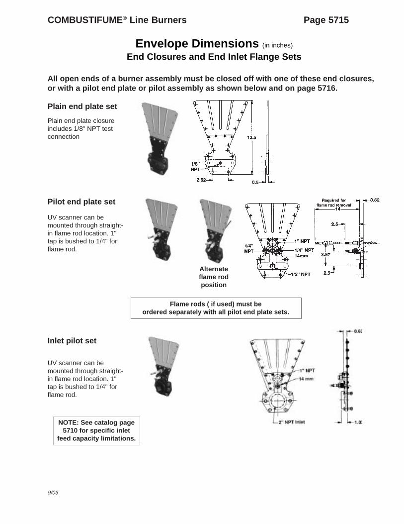
End Closures and End Inlet Flange Sets
All open ends of a burner assembly must be closed off with one of these end closures,or with a pilot end plate or pilot assembly as shown below and on page 5716.
Alternateflame rodposition
Inlet pilot set
UV scanner can bemounted through straight-in flame rod location. 1"tap is bushed to 1/4" forflame rod.
Flame rods ( if used) must beordered separately with all pilot end plate sets.
Plain end plate set
Plain end plate closureincludes 1/8" NPT testconnection
Pilot end plate set
UV scanner can bemounted through straight-in flame rod location. 1"tap is bushed to 1/4" forflame rod.
NOTE: See catalog page5710 for specific inlet
feed capacity limitations.
Page 5716 COMBUSTIFUME® Line Burners
Envelope Dimensions (in inches)
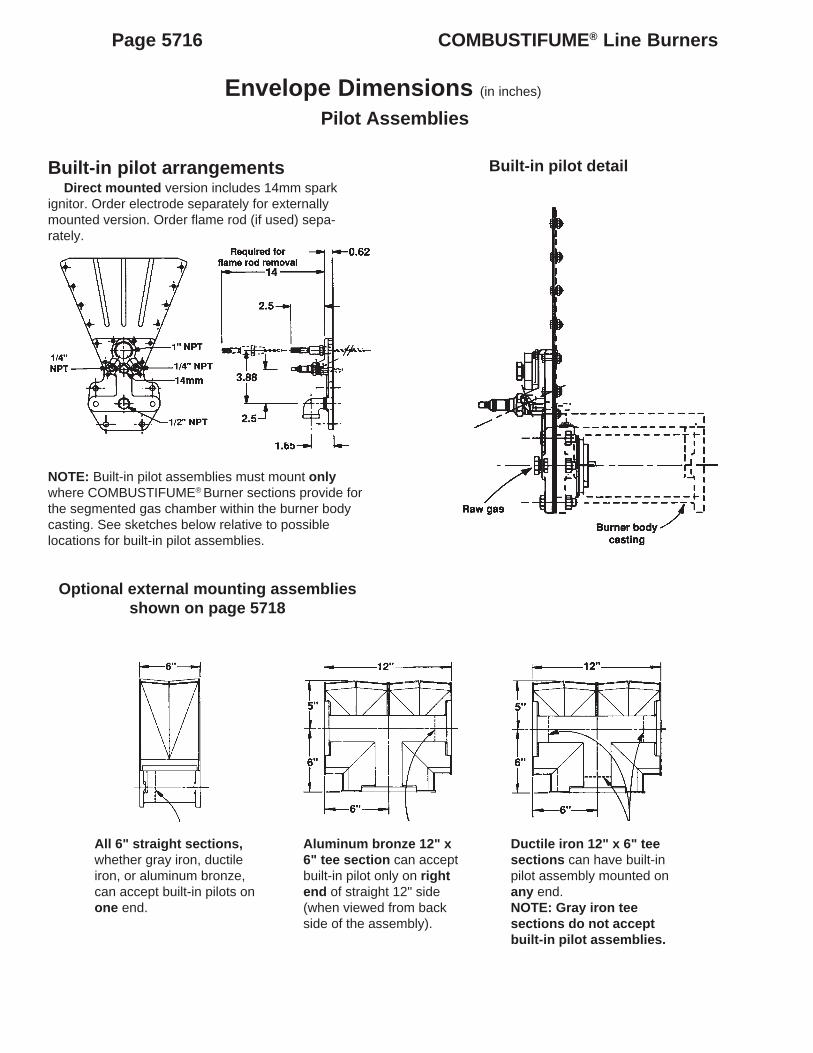
Pilot Assemblies
Built-in pilot arrangementsDirect mounted version includes 14mm spark
ignitor. Order electrode separately for externallymounted version. Order flame rod (if used) sepa-rately.
NOTE: Built-in pilot assemblies must mount onlywhere COMBUSTIFUME® Burner sections provide forthe segmented gas chamber within the burner bodycasting. See sketches below relative to possiblelocations for built-in pilot assemblies.
Optional external mounting assembliesshown on page 5718
Built-in pilot detail
All 6" straight sections,whether gray iron, ductileiron, or aluminum bronze,can accept built-in pilots onone end.
Aluminum bronze 12" x6" tee section can acceptbuilt-in pilot only on rightend of straight 12" side(when viewed from backside of the assembly).
Ductile iron 12" x 6" teesections can have built-inpilot assembly mounted onany end.NOTE: Gray iron teesections do not acceptbuilt-in pilot assemblies.
COMBUSTIFUME® Line Burners Page 5717
9/03
Envelope Dimensions (in inches)
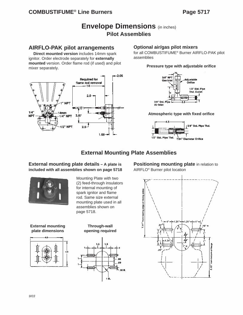
Pilot Assemblies
AIRFLO-PAK pilot arrangementsDirect mounted version includes 14mm spark
ignitor. Order electrode separately for externallymounted version. Order flame rod (if used) and pilotmixer separately.
Optional air/gas pilot mixersfor all COMBUSTIFUME® Burner AIRFLO-PAK pilotassemblies
Pressure type with adjustable orifice
Atmospheric type with fixed orifice
External Mounting Plate Assemblies
Positioning mounting plate in relation toAIRFLO® Burner pilot location
External mounting plate details – A plate isincluded with all assemblies shown on page 5718
Mounting Plate with two(2) feed-through insulatorsfor internal mounting ofspark ignitor and flamerod. Same size externalmounting plate used in allassemblies shown onpage 5718.
External mountingplate dimensions
Through-wallopening required
Page 5718 COMBUSTIFUME® Line Burners
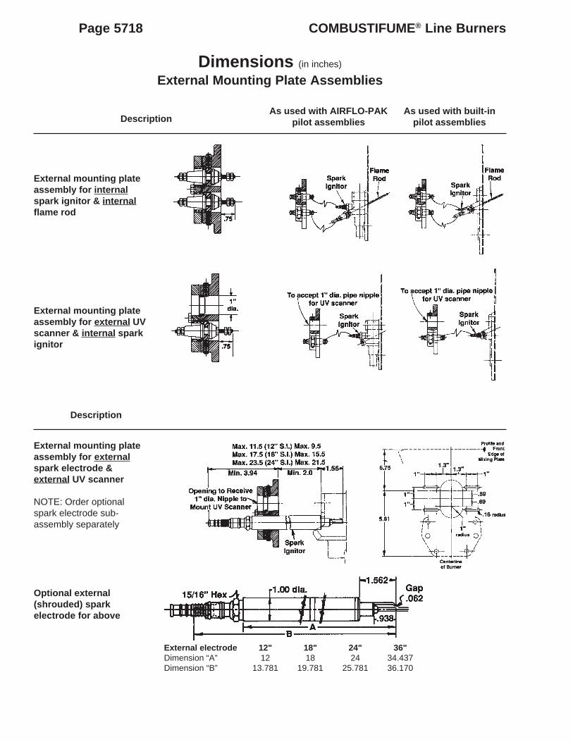
Dimensions (in inches)
External Mounting Plate Assemblies
As used with built-inpilot assemblies
As used with AIRFLO-PAKpilot assembliesDescription
Description
External mounting plateassembly for externalspark electrode &external UV scanner
NOTE: Order optionalspark electrode sub-assembly separately
External mounting plateassembly for external UVscanner & internal sparkignitor
External mounting plateassembly for internalspark ignitor & internalflame rod
Optional external(shrouded) sparkelectrode for above
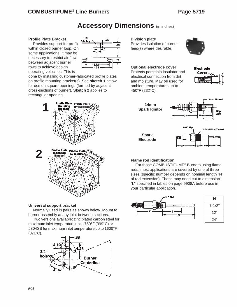
within closed burner loop. Onsome applications, it may benecessary to restrict air flowbetween adjacent burnerrows to achieve designoperating velocities. This isdone by installing customer-fabricated profile plateson profile mounting bracket(s). See sketch 1 belowfor use on square openings (formed by adjacentcross-sections of burner). Sketch 2 applies torectangular opening.
Universal support bracketNormally used in pairs as shown below. Mount to
burner assembly at any joint between sections.Two versions available: zinc plated carbon steel for
maximum inlet temperature up to 750°F (399°C) or#304SS for maximum inlet temperature up to 1600°F(871°C).
Division plateProvides isolation of burnerfeed(s) where desirable.
1
2
14mmSpark Ignitor
SparkElectrode
Flame rod identificationFor those COMBUSTIFUME® Burners using flame
rods, most applications are covered by one of threesizes (specific number depends on nominal length “N”of rod extension). These may need cut to dimension“L” specified in tables on page 9908A before use inyour particular application.
N
7-1/2"
12"
24"
Optional electrode coverProtects porcelain insulator andelectrical connection from dirtand moisture. May be used forambient temperatures up to450°F (232°C).
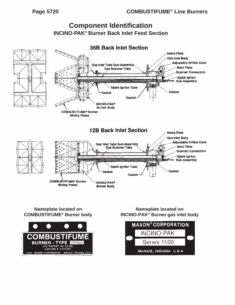
Page 5720 COMBUSTIFUME® Line Burners
Component IdentificationINCINO-PAK® Burner Back Inlet Feed Section
Nameplate located onINCINO-PAK® Burner gas inlet body
Nameplate located onCOMBUSTIFUME® Burner body
COMBUSTIFUME® Line Burners Page 5721
9/03
Component IdentificationCOMBUSTIFUME® Line Burners
ItemNumber
1 Burner body2 Back up bar (straight)3 Gasket, body (straight)4 Back up bar (inside)5 Gasket, inside6 Back up bar (outside)7 Burner body gasket (between joints)8 Support bracket gasket 18 GA9 6" mixing plate10 Corner mixing plate
12 M10 - 1.5 x 45 hex head cap screw13 M10 - 1.5 finished hex nut14 #10 -24 FLEX-LOK hex nut15 #10 -24 x 1/2" indented hex head machine screw16 #10 -24 x 2-1/4" indented hex head machine screw17 Washer18 #10 -24 x 3/8" indented hex head machine screw
19 M10 - 1.5 hex nut finished20 M10 - 1.5 x 35 hex head cap screw21 1/4" -20 x 3/4" hex head cap screw
Part DescriptionTo order replacement parts:1. Identify specific COMBUSTIFUME®
series/type from burner assemblyinformation plate pictured on page 5720.
2. Provide sketch of burner arrangement,as viewed from back (or casting side) ofassembly. For example:
3. Specify quantity of each replacementitem required from table at right.
Page 5722 COMBUSTIFUME® Line Burners
Notes
mCORPORATION
INDUSTRIAL COMBUSTION EQUIPMENT AND VALVES
Maxon practices a policy of continuous product improvement. It reserves the right to alter specifications without prior notice.
MUNCIE, INDIANA, USA
COMBUSTIFUME® Line Burners Page 5700-S-1
9/03
Installation Instructions
GeneralThese mounting instructions for COMBUSTIFUME®
Burners are in addition to the general AIRFLO® LineBurner installation instructions published onMaxon catalog pages 5000-S-1 through 5000-S-10.
Specific instructions are also offered for otherMaxon component items:– Shut-Off Valves (pages 6000-S-1 through S-14)– Flow Control Valves (pages 7000-S-1 through S-4)– Mixing Tubes (pages 3200-S-1 through S-6)
Read complete instructions before proceeding,and familiarize yourself with all the system’s equip-ment components. Verify that your equipment hasbeen installed in accordance with the originalmanufacturer’s current instructions.
Clean fuel lines are essential to prevent blockageof pipe train components or burner gas ports. All dirt,scale and pipe dope should be blown out of any newgas line before actually connecting to the burnersystem.
Main gas shut-off cock should be upstream ofboth main gas regulator and pilot line take-off. Use itto shut off fuel to both pilot and main burner duringshutdown periods of more than a few hours. MaxonControl Valves, such as the Series “CV” andMICRO-RATIO® Valves, are not intended for tightshut-off.
Main gas regulator is essential to maintain auniform system supply pressure. A separate regulatorshould be provided in the branch leading to eachburner system if more than one is served by a com-mon main. Size regulator for full system capacity atrequired pressure, including pipe train losses and anypositive chamber pressure. Follow the instructionsattached to the regulator during installation.
Pilot take-off should be upstream of main gasregulator but downstream of main gas cock. It shouldnormally include its own pilot gas regulator (selectedto meet pilot flow and pressure needs), a solenoidvalve and shut-off cock. An adjustable gas orifice atthe pilot inlet simplifies adjustment.
Appropriate pilots should be provided which arecompatible with the type of burner and control systembeing used.
Fuel shut-off valves (when properly connected toa safety control system) shut the fuel supply off with aloss of electrical power. Manual reset valves requireoperator attendance each time the system is startedup (or restarted after a shut-down). Motorized shut-off valves permit automatic start/restart when usedwith appropriate control system.
Test connections are essential for burner adjust-ment. At a minimum, they should be provided down-stream of any mixing tube and at each burner inlet.Test connections should never be installed in elbowsor pipe tees. Test connections must be pluggedexcept when readings are being taken.
Bolt Torque Tightening1. Apply Never-Seez (anti-seize and lubricating
compound) to the threads of the bolts to improvethe pre-loading of the gasket.
2. Tighten the bolts to 1/2 the specified value (seetable below), starting at position 1 and working toposition 6.
3. Tighten the bolts to the full torque value, starting atposition 1 and working to position 6.
4. Tighten the bolts again to the full value starting atposition 1 and working to position 6.
MUNCIE, INDIANA, USA INDUSTRIAL COMBUSTION EQUIPMENT AND VALVES
Maxon practices a policy of continuous product improvement. It reserves the right to alter specifications without prior notice.
Page 5700-S-2 COMBUSTIFUME® Line Burners
Installation Instructions
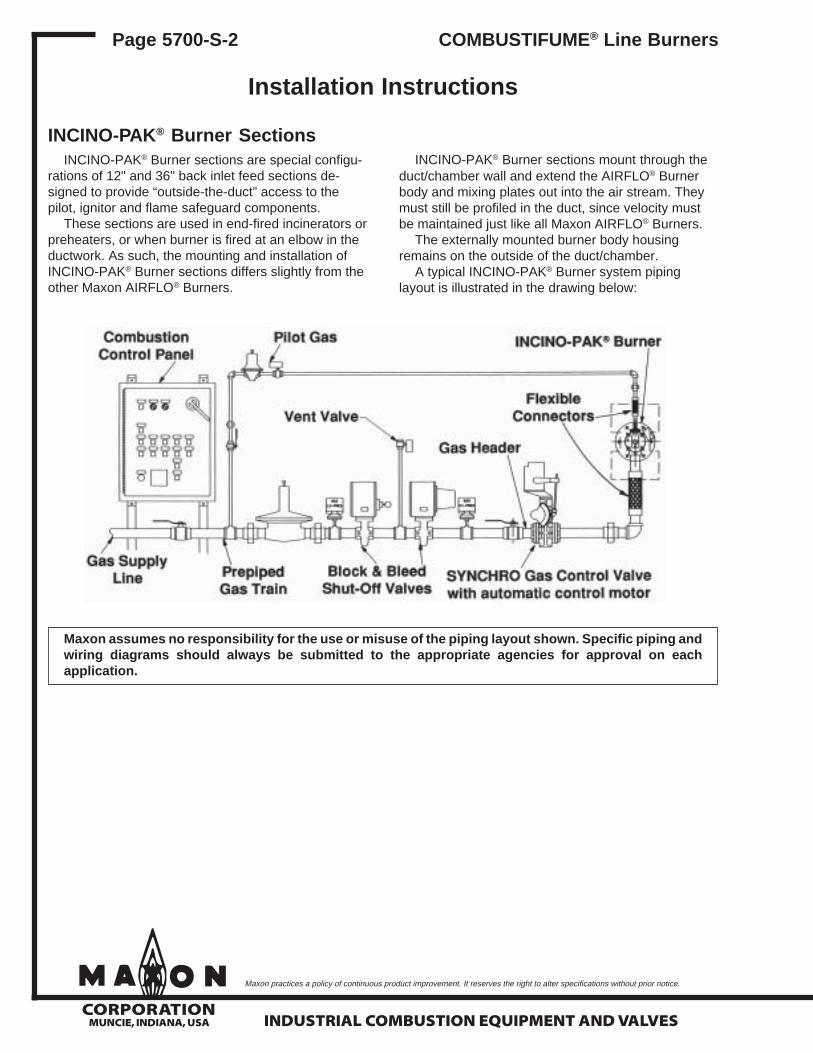
INCINO-PAK® Burner SectionsINCINO-PAK® Burner sections are special configu-
rations of 12" and 36" back inlet feed sections de-signed to provide “outside-the-duct” access to thepilot, ignitor and flame safeguard components.
These sections are used in end-fired incinerators orpreheaters, or when burner is fired at an elbow in theductwork. As such, the mounting and installation ofINCINO-PAK® Burner sections differs slightly from theother Maxon AIRFLO® Burners.
INCINO-PAK® Burner sections mount through theduct/chamber wall and extend the AIRFLO® Burnerbody and mixing plates out into the air stream. Theymust still be profiled in the duct, since velocity mustbe maintained just like all Maxon AIRFLO® Burners.
The externally mounted burner body housingremains on the outside of the duct/chamber.
A typical INCINO-PAK® Burner system pipinglayout is illustrated in the drawing below:
Maxon assumes no responsibility for the use or misuse of the piping layout shown. Specific piping andwiring diagrams should always be submitted to the appropriate agencies for approval on eachapplication.
mCORPORATION
INDUSTRIAL COMBUSTION EQUIPMENT AND VALVES
Maxon practices a policy of continuous product improvement. It reserves the right to alter specifications without prior notice.
MUNCIE, INDIANA, USA
Installation Instructions
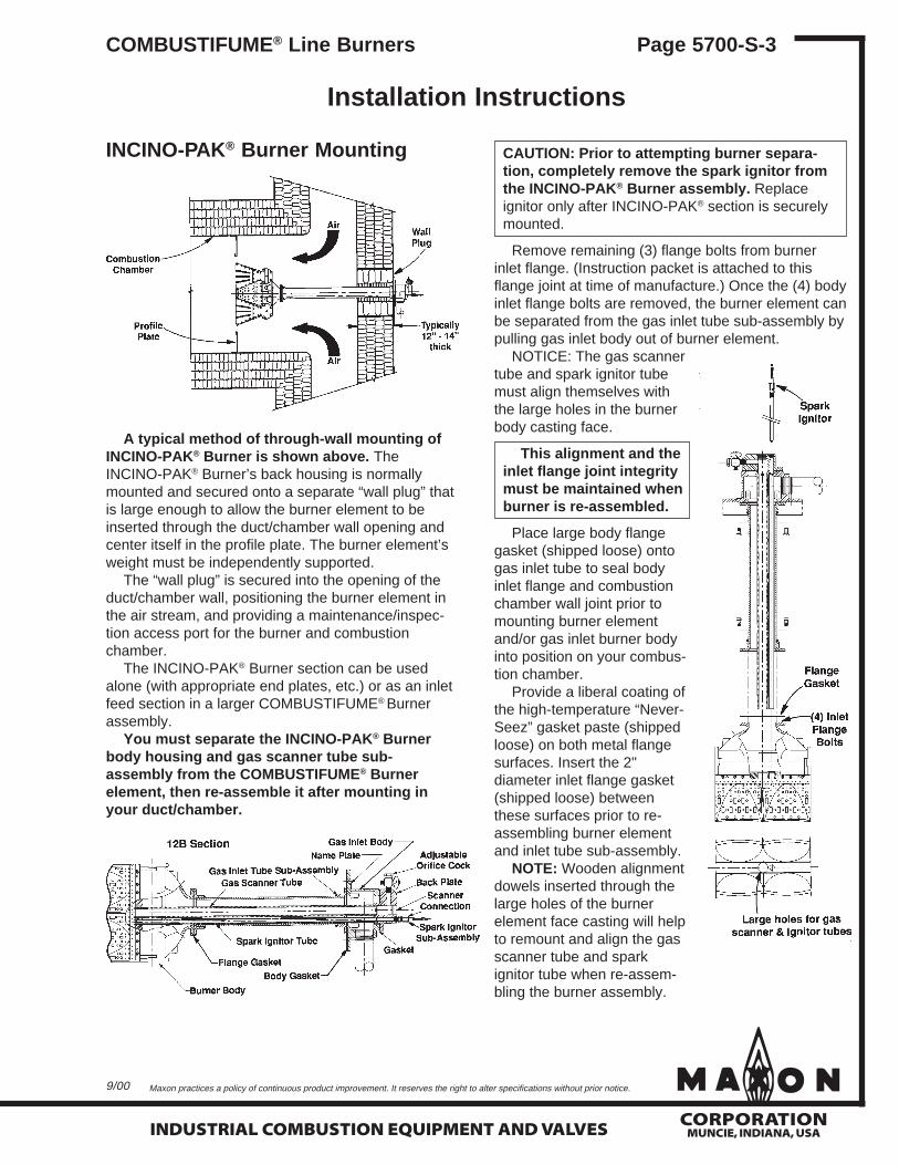
INCINO-PAK® Burner Mounting
A typical method of through-wall mounting ofINCINO-PAK® Burner is shown above. TheINCINO-PAK® Burner’s back housing is normallymounted and secured onto a separate “wall plug” thatis large enough to allow the burner element to beinserted through the duct/chamber wall opening andcenter itself in the profile plate. The burner element’sweight must be independently supported.
The “wall plug” is secured into the opening of theduct/chamber wall, positioning the burner element inthe air stream, and providing a maintenance/inspec-tion access port for the burner and combustionchamber.
The INCINO-PAK® Burner section can be usedalone (with appropriate end plates, etc.) or as an inletfeed section in a larger COMBUSTIFUME® Burnerassembly.
You must separate the INCINO-PAK® Burnerbody housing and gas scanner tube sub-assembly from the COMBUSTIFUME® Burnerelement, then re-assemble it after mounting inyour duct/chamber.
CAUTION: Prior to attempting burner separa-tion, completely remove the spark ignitor fromthe INCINO-PAK® Burner assembly. Replaceignitor only after INCINO-PAK® section is securelymounted.
Remove remaining (3) flange bolts from burnerinlet flange. (Instruction packet is attached to thisflange joint at time of manufacture.) Once the (4) bodyinlet flange bolts are removed, the burner element canbe separated from the gas inlet tube sub-assembly bypulling gas inlet body out of burner element.
NOTICE: The gas scannertube and spark ignitor tubemust align themselves withthe large holes in the burnerbody casting face.
This alignment and theinlet flange joint integritymust be maintained whenburner is re-assembled.
Place large body flangegasket (shipped loose) ontogas inlet tube to seal bodyinlet flange and combustionchamber wall joint prior tomounting burner elementand/or gas inlet burner bodyinto position on your combus-tion chamber.
Provide a liberal coating ofthe high-temperature “Never-Seez” gasket paste (shippedloose) on both metal flangesurfaces. Insert the 2"diameter inlet flange gasket(shipped loose) betweenthese surfaces prior to re-assembling burner elementand inlet tube sub-assembly.
NOTE: Wooden alignmentdowels inserted through thelarge holes of the burnerelement face casting will helpto remount and align the gasscanner tube and sparkignitor tube when re-assem-bling the burner assembly.
COMBUSTIFUME® Line Burners Page 5700-S-3
9/00
mCORPORATION
MUNCIE, INDIANA, USA INDUSTRIAL COMBUSTION EQUIPMENT AND VALVES
Maxon practices a policy of continuous product improvement. It reserves the right to alter specifications without prior notice.
Page 5700-S-4 COMBUSTIFUME® Line Burners
Raw Gas Burner Start-Up Instructions
Read complete instructions before proceeding, andfamiliarize yourself with all the system’s equipmentcomponents. Verify that your equipment has beeninstalled in accordance with the originalmanufacturer’s current instructions.
CAUTION: Initial adjustment and light-off shouldbe undertaken only by trained and experiencedpersonnel familiar with combustion systems,with control/safety circuitry and with knowledgeof the overall installation. Instructions providedby the company and/or individuals responsiblefor the manufacture and/or overall installation ofcomplete system incorporating Maxon burnerstake precedence over these provided by Maxon.If Maxon instructions conflict with any codes orregulations, contact Maxon Corporation beforeattempting start-up.
For initial burner start-up of rawgas burner system:
1. Close all burner fuel valves or cocks. Makepreliminary adjustments to fuel gas regulators.Remove pilot and main gas regulators’ adjustingscrew covers. Turn adjusting screw down(clockwise) to approximately mid-position. Closepilot gas adjustable orifice screw by turning inclockwise until it stops. (Do not over-tighten.)Then back out the adjustable orifice (counter-clockwise) approximately 2-3 turns.
2. Check all electric circuitry. Verify that allcontrol devices and interlocks are operable andfunctioning within their respective settings/ranges. Be sure all air and gas manifolds aretight and that test ports are plugged if not beingused.
3. Check that all duct and chamber dampersare properly positioned and locked intooperating positions.
Initial start-up adjustment should only be accom-plished during a “manual” burner control mode.
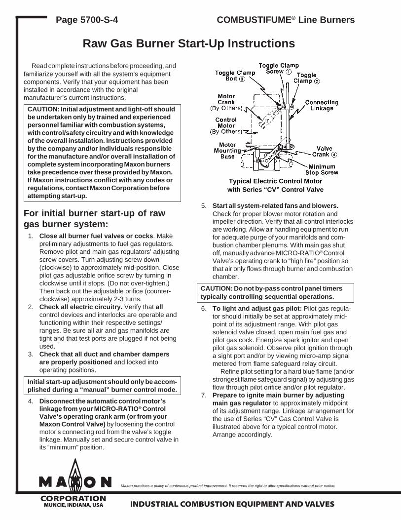
4. Disconnect the automatic control motor’slinkage from your MICRO-RATIO® ControlValve’s operating crank arm (or from yourMaxon Control Valve) by loosening the controlmotor’s connecting rod from the valve’s togglelinkage. Manually set and secure control valve inits “minimum” position.
5. Start all system-related fans and blowers.Check for proper blower motor rotation andimpeller direction. Verify that all control interlocksare working. Allow air handling equipment to runfor adequate purge of your manifolds and com-bustion chamber plenums. With main gas shutoff, manually advance MICRO-RATIO® ControlValve’s operating crank to “high fire” position sothat air only flows through burner and combustionchamber.
CAUTION: Do not by-pass control panel timerstypically controlling sequential operations.
6. To light and adjust gas pilot: Pilot gas regula-tor should initially be set at approximately mid-point of its adjustment range. With pilot gassolenoid valve closed, open main fuel gas andpilot gas cock. Energize spark ignitor and openpilot gas solenoid. Observe pilot ignition througha sight port and/or by viewing micro-amp signalmetered from flame safeguard relay circuit.
Refine pilot setting for a hard blue flame (and/orstrongest flame safeguard signal) by adjusting gasflow through pilot orifice and/or pilot regulator.
7. Prepare to ignite main burner by adjustingmain gas regulator to approximately midpointof its adjustment range. Linkage arrangement forthe use of Series “CV” Gas Control Valve isillustrated above for a typical control motor.Arrange accordingly.
Typical Electric Control Motorwith Series “CV” Control Valve
mCORPORATION
INDUSTRIAL COMBUSTION EQUIPMENT AND VALVES
Maxon practices a policy of continuous product improvement. It reserves the right to alter specifications without prior notice.
MUNCIE, INDIANA, USA
Raw Gas Burner Start-Up Instructions
8. With control valve at “minimum”, ignite mainburner by opening main fuel shut-off valve.Adjust main gas regulator to give the desiredoutlet pressure. Refine pilot adjustment if it hasbeen affected. Adjust burner “minimum” byturning in on the minimum stop screw of the gascontrol valve until stable flame appears in thenarrow zipper channel at the base of burnermixing plates.
A good minimum fire should provide uniformflame across the entire burner face, containedwithin the zipper flame channel at the base ofburner mixing plates. Any thin spots or gapsindicate uneven air velocity over the burnerwhich must be corrected or a higher minimumfire established by continuing to turn in on theminimum stop screw.
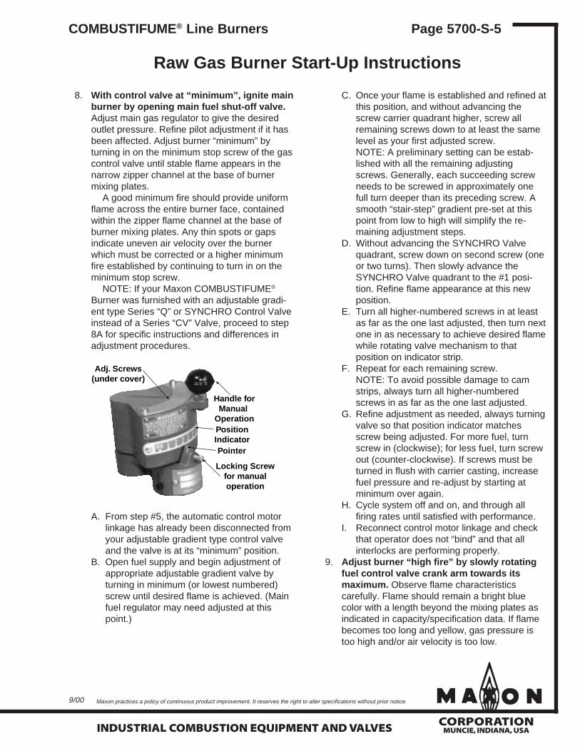
NOTE: If your Maxon COMBUSTIFUME®
Burner was furnished with an adjustable gradi-ent type Series “Q” or SYNCHRO Control Valveinstead of a Series “CV” Valve, proceed to step8A for specific instructions and differences inadjustment procedures.
C. Once your flame is established and refined atthis position, and without advancing thescrew carrier quadrant higher, screw allremaining screws down to at least the samelevel as your first adjusted screw.NOTE: A preliminary setting can be estab-lished with all the remaining adjustingscrews. Generally, each succeeding screwneeds to be screwed in approximately onefull turn deeper than its preceding screw. Asmooth “stair-step” gradient pre-set at thispoint from low to high will simplify the re-maining adjustment steps.
D. Without advancing the SYNCHRO Valvequadrant, screw down on second screw (oneor two turns). Then slowly advance theSYNCHRO Valve quadrant to the #1 posi-tion. Refine flame appearance at this newposition.
E. Turn all higher-numbered screws in at leastas far as the one last adjusted, then turn nextone in as necessary to achieve desired flamewhile rotating valve mechanism to thatposition on indicator strip.
F. Repeat for each remaining screw.NOTE: To avoid possible damage to camstrips, always turn all higher-numberedscrews in as far as the one last adjusted.
G. Refine adjustment as needed, always turningvalve so that position indicator matchesscrew being adjusted. For more fuel, turnscrew in (clockwise); for less fuel, turn screwout (counter-clockwise). If screws must beturned in flush with carrier casting, increasefuel pressure and re-adjust by starting atminimum over again.
H. Cycle system off and on, and through allfiring rates until satisfied with performance.
I. Reconnect control motor linkage and checkthat operator does not “bind” and that allinterlocks are performing properly.
9. Adjust burner “high fire” by slowly rotatingfuel control valve crank arm towards itsmaximum. Observe flame characteristicscarefully. Flame should remain a bright bluecolor with a length beyond the mixing plates asindicated in capacity/specification data. If flamebecomes too long and yellow, gas pressure istoo high and/or air velocity is too low.
A. From step #5, the automatic control motorlinkage has already been disconnected fromyour adjustable gradient type control valveand the valve is at its “minimum” position.
B. Open fuel supply and begin adjustment ofappropriate adjustable gradient valve byturning in minimum (or lowest numbered)screw until desired flame is achieved. (Mainfuel regulator may need adjusted at thispoint.)
COMBUSTIFUME® Line Burners Page 5700-S-5
9/00
Adj. Screws(under cover)
Handle forManual
OperationPositionIndicatorPointer
Locking Screwfor manualoperation
mCORPORATION
MUNCIE, INDIANA, USA INDUSTRIAL COMBUSTION EQUIPMENT AND VALVES
Maxon practices a policy of continuous product improvement. It reserves the right to alter specifications without prior notice.
Page 5700-S-6 COMBUSTIFUME® Line Burners
Raw Gas Burner Start-Up Instructions
NOTE: Dust and/or chemicals entrained intopassing air stream may affect physical color offlame. In this case, adjust burner for stable flameshape and geometry.
To measure gas pressure, connect watercolumn (manometer) to the test connection inburner’s end plate. To determine air velocity,use a velometer at the profile opening. Correctvelocities by increasing or decreasing profileopening size.
If flame is too short, gas pressure may be toolow and should be increased or velocities aretoo high and may need to be decreased. Notethat air velocities should be measured only whenthe fan is handling air at the desired controltemperature.
The desired maximum capacity may beachieved with less than full control valve open-ing. Mark with a pencil or scribe the point onvalve crank arm where the desired maximum isobtained, then return crank arm to low positionand shut system off.
10. Referring to illustration on page 5700-S-4,reconnect control motor linkage (with controlmotor in low or minimum position) by looseningtoggle clamp screw ➀ and moving toggle clamp➁ along the connecting linkage to a point wheretoggle clamp bolt ➂ can be placed at theoutermost position of control motor crank slot.Then tighten toggle clamp screw ➀ , thus fixingclamp to linkage.
Allowing toggle clamp bolt ➂ to slide in thecrank arm slot, cycle control motor towards itsmaximum position and move fuel control valve
crank ➃ to the previously-determined maximumfiring rate position. Tighten toggle clamp bolt ➂ ,thus fixing clamp to motor crank.
Cycle control motor back to minimum, watch-ing carefully that it does not bind before reachingminimum.
If it is stopped or if minimum is not reached,loosen toggle clamp screw ➀ and move toggleclamp along the connecting linkage so bothmotor and valve can assume their minimumpositions. Then retighten toggle clamp screw ➀ .Refine adjustment by cycling several timesbetween low and high control motor positionwhile re-adjusting toggle clamp bolt ➂ asnecessary until control motor travels through itsfull cycle while moving control valve crank armfrom its minimum only up to the desired maxi-mum previously determined.
11. Relight burner and cycle control system fromlow to high fire several times to observeperformance. Refine adjustments of pilot andmain burner minimum if necessary.
Warning: Test every UV flame sensor systemfor dangerous spark excitation from ignitorsand other burners, as well as other possiblesources of direct or reflected UV radiation.
12. Check carefully that all interlocks and limitsare in full operating condition and beforesystem is placed into full service, instructoperator personnel on proper start-up,operation and shut-down of system, estab-lishing written instructions for reference.
Raw Gas Firing Start-Up Instructions for INCINO-PAK® Burner SectionsINCINO-PAK® Burner
sections are started up in thesame manner as otherCOMBUSTIFUME® Burners,except the designed manifoldingfor the raw gas brings all thecomponents to the “outside” ofthe duct.
Your control valve is adjustedin the same manner withINCINO-PAK® Burners asdescribed earlier for raw gasburner start-up instructions.
mCORPORATION
INDUSTRIAL COMBUSTION EQUIPMENT AND VALVES
Maxon practices a policy of continuous product improvement. It reserves the right to alter specifications without prior notice.
MUNCIE, INDIANA, USA
Partial-Premixed Burner Start-Up Instructions
COMBUSTIFUME® Line Burners may also beinstalled in oxygen-starved air streams. In thoseapplications, a full or partial premixed air/gas mixturemust be supplied to your COMBUSTIFUME® Burnerto support proper combustion. With “partial-premixed”COMBUSTIFUME® Burner systems, a Series “HG”Mixing Tube with MICRO-RATIO® Control Valve isoften used to premix gas and air prior to its introduc-tion to the COMBUSTIFUME® Line Burner assembly.
A typical “HG” Mixing Tube system pipinglayout is illustrated below.
Maxon assumes no responsibility for the use ormisuse of the piping layout shown. Specificpiping and wiring diagrams should always besubmitted to the appropriate agencies forapproval on each application.
Combustion air blower provides the air (oxygen)supply to your combustion system and is essential tothe mixing of fuel gas. It should be located in thecoolest, cleanest position that you can find near theburner itself. It must not be exposed to direct radiantheat or positioned where it might draw in the inertgases or hot air rising from a furnace or oven. Ifproblems exist, consider filters, relocation and/orducting of an outside fresh air supply.
Minimize combustion air pressure drop betweenblower and mixing tube. Keep a minimum straight runof four pipe diameters into the mixer air inlet. Down-stream piping from mixer to burner should be kept asshort as possible.
Electrical service must match the voltage, phaseand cycle of all electrical system components and becompatible with burner nameplate ratings. Insure thatall normal control safeguards are satisfied. Combus-tion air blower should continue to run after shutdownto allow burner to cool.
Gas supply piping must be large enough tomaintain the required fuel pressures cataloged for theparticular burner size used with burner operating atfull-rated capacity.
Natural gas pressure generally required (asmeasured at the mixer gas inlet) is 1 PSIG higherthan air pressure for “HG” Mixing Tubes.
Anything more than minimal distance or pipingturns may necessitate “oversizing” piping runs to keeppressure drops within acceptable ranges.
Inlet pipe leading to any burner should be at leastfour pipe diameters in length. If multiple burners arefed from a single gas train, care should be taken tominimize pressure drop and give maximum uniformity.
CAUTION: Do not install any shut-off device inthe air/gas mixture line.
For initial burner start-up of partial-premixed burner system:
Start-up steps #1 through #5 are the same forpartial-premix and raw gas burner systems. See page5700-S-4 for first five start-up steps, then continuewith step #6 below.
6. Check minimum mixture pressure at burnersby turning the MICRO-RATIO® Control Valve toits minimum position and reading differential airpressure only at each burner with a watercolumn manometer. Any reading below 0.25" wcdifferential (natural gas) requires re-adjustmentas described below.
Setting minimum mixture pressure with aMICRO-RATIO® Control Valve and Series“HG” Mixing Tube system:
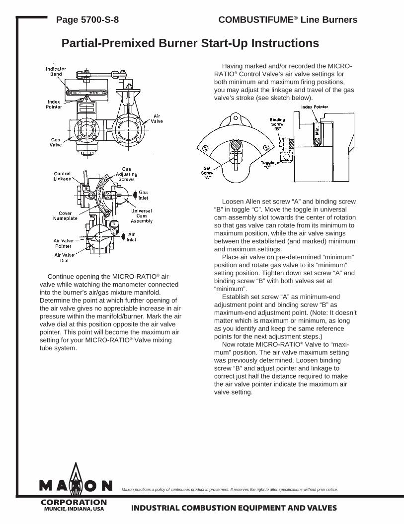
If minimum mixture pressure must be in-creased, open the MICRO-RATIO® air valveslowly (by turning toward higher-numberedpositions) until the required differential air(mixture) pressure is reached, then mark airvalve dial at the position opposite pointer. Thispoint will become the minimum air setting foryour MICRO-RATIO® Valve mixing tube system(see sketch on page 5700-S-8).
COMBUSTIFUME® Line Burners Page 5700-S-7
9/00
mCORPORATION
MUNCIE, INDIANA, USA INDUSTRIAL COMBUSTION EQUIPMENT AND VALVES
Maxon practices a policy of continuous product improvement. It reserves the right to alter specifications without prior notice.
Page 5700-S-8 COMBUSTIFUME® Line Burners
Partial-Premixed Burner Start-Up Instructions
Continue opening the MICRO-RATIO® airvalve while watching the manometer connectedinto the burner’s air/gas mixture manifold.Determine the point at which further opening ofthe air valve gives no appreciable increase in airpressure within the manifold/burner. Mark the airvalve dial at this position opposite the air valvepointer. This point will become the maximum airsetting for your MICRO-RATIO® Valve mixingtube system.
Having marked and/or recorded the MICRO-RATIO® Control Valve’s air valve settings forboth minimum and maximum firing positions,you may adjust the linkage and travel of the gasvalve’s stroke (see sketch below).
Loosen Allen set screw “A” and binding screw“B” in toggle “C”. Move the toggle in universalcam assembly slot towards the center of rotationso that gas valve can rotate from its minimum tomaximum position, while the air valve swingsbetween the established (and marked) minimumand maximum settings.
Place air valve on pre-determined “minimum”position and rotate gas valve to its “minimum”setting position. Tighten down set screw “A” andbinding screw “B” with both valves set at“minimum”.
Establish set screw “A” as minimum-endadjustment point and binding screw “B” asmaximum-end adjustment point. (Note: It doesn’tmatter which is maximum or minimum, as longas you identify and keep the same referencepoints for the next adjustment steps.)
Now rotate MICRO-RATIO® Valve to “maxi-mum” position. The air valve maximum settingwas previously determined. Loosen bindingscrew “B” and adjust pointer and linkage tocorrect just half the distance required to makethe air valve pointer indicate the maximum airvalve setting.
mCORPORATION
INDUSTRIAL COMBUSTION EQUIPMENT AND VALVES
Maxon practices a policy of continuous product improvement. It reserves the right to alter specifications without prior notice.
MUNCIE, INDIANA, USA
Partial-Premixed Burner Start-Up Instructions
9/00
COMBUSTIFUME® Line Burners Page 5700-S-9
Re-tighten binding screw “B” and return theMICRO-RATIO® Valve to the “minimum” airsetting.
This time, loosen set screw “A” and againcorrect for just half the distance required tomake the air valve pointer indicate the minimumair valve setting.
Re-tighten set screw “A” and again return theMICRO-RATIO® Valve to its maximum position.
Similarly, correct one half the distance withbinding screw “B” for the maximum setting, etc.
Continue this adjustment procedure until thegas and air valves reach their minimum andmaximum positions simultaneously. Normally,this is accomplished within seven adjustments.
7. Remove cover plate from screw carrier camassembly and turn all adjusting screws counter-clockwise until flush with outer surface of casting(new equipment is shipped this way).
8. Open main and pilot gas cocks and light firstburner pilot following instructions appropriate forthat burner and pilot type. If multiple pilots areused, open individual cocks and adjust each inturn.
To light and adjust gas pilot: Check toinsure pilot combustion air supply is flowing toany pressure pilot mixer. Pilot gas regulatorshould initially be set at approximately midpointof its adjustment range. With pilot gas solenoidclosed, open main fuel gas and pilot gas cock.Energize spark ignitor and pilot gas solenoid.Observe pilot ignition through sight port of pilotassembly and/or by viewing micro-amp signalmetered from flame safeguard relay circuit.
Refine pilot setting for a hard blue flame(and/or strongest micro-amp signal) by adjustinggas flow through pilot orifice and/or pilotregulator.
Shut off pilot gas cock to extinguish pilot fire.Re-open and confirm easy re-ignition severaltimes. The flame safeguard relays should nowpower the main fuel shut-off valves.
9. Light main burners at minimum as follows:First, turn MICRO-RATIO® Valve to its
minimum setting (which may be at position 1 or2 after completing step 6), then open fuel shut-off valve and turn corresponding screw in(clockwise) until flame ignites at all burnernozzles. (This may take several turns of thescrew.)
NOTE: At this point, it is more important to getany kind of a flame as soon as possible. Theflame geometry can be adjusted and refined asneeded later.
Continue turning in slowly until flame be-comes noticeably rich (usually purple or greenwith a slight yellow tip). Then slowly back thescrew out until the flame becomes bright blue.
A good minimum fire should provide uniformflame across the entire burner face, containedwithin the zipper flame channel at the base ofburner mixing plates. Any thin spots or gapsindicate uneven air velocity over the burnerwhich must be corrected or a higher minimumfire established by continuing to turn in on theminimum stop screw.
10. Once your flame is established and refined atthis position, and without advancing the screwcarrier quadrant higher, screw all remainingscrews down to at least the same level as yourfirst adjusted screw.NOTE: A preliminary setting can be establishedwith all the remaining adjusting screws. Gener-ally, each succeeding screw needs to bescrewed in approximately one full turn more(clockwise) than its preceding screw. A smooth“stair-step” gradient pre-set at this point from lowto high will simplify the remaining adjustmentsteps.
CAUTION: If flame is extinguished, immediatelyreturn MICRO-RATIO® Control Valve tominimum position and shut off fuel (if flamesafeguard has not already done so). Turn inslightly on adjusting screw at point whereignition was lost, then return valve to minimumposition, re-establish pilot, open fuel valve andverify ignition.
11. Without advancing the valve quadrant, screwdown clockwise on second screw (one or twoturns). Then slowly advance the screw carrierquadrant to the #1 position. Adjust flameappearance at this new position.NOTE: If firing chamber is of refractory construc-tion, allow your burner system to operate at thislow setting for the necessary dry/cure-out timeperiod recommended by the chamber or refrac-tory manufacturer. Then continue adjustments ofvalve.
mCORPORATION
MUNCIE, INDIANA, USA INDUSTRIAL COMBUSTION EQUIPMENT AND VALVES
Maxon practices a policy of continuous product improvement. It reserves the right to alter specifications without prior notice.
Page 5700-S-10 COMBUSTIFUME® Line Burners
Partial-Premixed Burner Start-Up Instructions
12. Again, without moving valve, bring the third andall remaining adjusting screws down to the samelevel as the second screw.NOTE: If approximate pre-set gradient wasmade earlier, the remaining screws will alreadybe at or below appropriate levels.
Progressively work your way up through eachadjusting screw position, developing a smoothprogression slope from your first screw to the“maximum” position.
As each is adjusted, you must turn theremaining unadjusted screws in at least that farto prevent possible damage to flexible camstrips inside the screw carrier cam assembly.
Turning a screw in “clockwise” gives moregas at that setting; turning it out gives less.NOTE: To adjust the flame at any position, youmust move the valve quadrant to the numberyou desire to adjust. This aligns the adjustingscrew directly on top of the fuel valve plunger. Aresulting adjustment of the screw is directlyapplied to the fuel valve plunger and its intercon-nected valve body linkage.
13. Cycle burner from minimum to maximum andrefine adjustment, if necessary.
For operation with interrupted pilot (asrecommended), shut off pilots and cycle burnerfrom minimum to maximum and back severaltimes to verify the flame is maintained.
CAUTION: After completing previously listedsteps, check all interlocking safety componentsand circuitry to prove that they are properlyinstalled, correctly set, and fully operational. Ifin doubt, shut the system down, close main andpilot cocks, and contact responsible individualbefore proceeding further.
14. Reconnect linkage to control motor, plug alltest connections, replace equipment cover capsand tighten linkage screws.
15. Check out overall system operation by cyclingthrough light-off at minimum, interrupting pilot,and allowing temperature control system tocycle burner from minimum to maximum andreturn.
Re-check all safety system interlocks forproper setting and operation.
WARNING: Test every UV installation fordangerous spark excitation from ignitors andother possible sources of direct or reflected UVradiation. Use only gas-tight scannerconnections.
16. Before system is placed into full service,instruct operator personnel on proper start-up,operation and shut-down of system. Establishwritten instructions for their future reference.