8/31/2015 Combustion Gas Turbines http://articles.compressionjobs.com/articles/oilfield101/168gasturbinesprincipleslubecontrolsystemsoverspeed?tmpl=component&print=1&page= 1/11 Combustion Gas Turbines Written by Norrie Wednesday, 13 January 2010 10:12 INTRODUCTION In operating areas where suitable water for steam generation is in short supply and natural gas is plentiful, Combustion Gas Turbines are used to drive other Machines. A Combustion Gas Turbine, like any other internal combustion engine, is a machine which converts the Thermal Energy of burning fuel into useful power which, in turn is converted into Mechanical Energy. Just like a windmill, waterwheel or steam turbine, a combustion gas turbine depends on the flow of fluid for its driving force. The driving fluid in this case, is very high temperature, compressed air. Let us first begin again with our pinwheel. If we place a running fan in front of the pinwheel, the air flow from the fan will cause the pinwheel to rotate. Now, in theory, if we connect the fan to the pinwheel by a shaft, when the fan is running, the pinwheel is rotating and, through the shaft should rotate the fan. At this point we should be able to switch off the power to the fan and the system will continue to run the pinwheel driving the fan and the air from the fan driving the pinwheel. In practice, this is not possible due to friction and other power losses in the system. (Figure. 14) However, if we can add extra energy to the air flow from the fan in sufficient quantity, then this will maintain the pinwheel rotation which, in turn, will maintain the fan rotation. In (Figure. 15), we have added a combustion chamber between the fan and the pinwheel. By burning fuel in the combustion chamber, the thermal energy of the air is greatly increased and this increase in energy will maintain the rotation when the fan power is switched off. Figure. 14 TURBINE BASICS Increasing the Energy of the Air
In operating areas where suitable water for steam generation is in short supply and natural gas is plentiful,Combustion Gas Turbines are used to drive other Machines. A Combustion Gas Turbine, like any other internalcombustion engine, is a machine which converts the Thermal Energy of burning fuel into useful power which, in turnis converted into Mechanical Energy. Just like a windmill, waterwheel or steam turbine, a combustion gas turbinedepends on the flow of fluid for its driving force. The driving fluid in this case, is very high temperature, compressedair. Let us first begin again with our pinwheel. If we place a running fan in front of the pinwheel, the air flow fromthe fan will cause the pinwheel to rotate. Now, in theory, if we connect the fan to the pinwheel by a shaft, when thefan is running, the pinwheel is rotating and, through the shaft should rotate the fan. At this point we should be able toswitch off the power to the fan and the system will continue to run the pinwheel driving the fan and the air fromthe fan driving the pinwheel.
In practice, this is not possible due to friction and other power losses in the system. (Figure. 14) However, if we canadd extra energy to the air flow from the fan in sufficient quantity, then this will maintain the pinwheel rotationwhich, in turn, will maintain the fan rotation. In (Figure. 15), we have added a combustion chamber between the fanand the pinwheel. By burning fuel in the combustion chamber, the thermal energy of the air is greatly increased andthis increase in energy will maintain the rotation when the fan power is switched off. Figure. 14
(Figure. 16), Shows the basic layout of a combustion gas turbine as compared to the operation of a reciprocatinginternal combustion engine. The advantages of the turbine are, that it has less moving parts, it is smoother inoperation and can produce much more power. In a Steam Turbine, the driving force comes from the Potential (stored)energy of high pressure, high temperature steam. The conversion of this energy into mechanical energy takes placewhen the pressure is released and changed to velocity by the nozzles, which rotates the turbine rotor. This type ofturbine may be classed as an 'External Combustion Engine’ because the heat energy is added outside of the machineby the boilers. All gas turbines are similar in operation, but different makes and models have varying configurationsand design. The main parts of a ‘Combustion Gas Turbine’ consist of the following:The Air Compressor; The Combustion Chamber; The Compressor (HP) and Load (LP) Turbines.
1. THE AIR COMPRESSOR (Figure. 17)
This is generally an ‘AXIAL FLOW COMPRESSOR’ and can be classed as the exact opposite of a turbine. (Aturbine needs high energy fluid flow to cause rotation). An Axial Flow compressor needs a mechanical driver for itsoperation. The compressor itself consists of Rotors and Stators each having blades. The rotor blades are like those ofthe turbine and are similar to fan blades. As the wheels rotate, air is pushed forward with an increase in energy asvelocity. The air then enters the stator blades where the velocity is decreased. This increases the pressure; (Bernoulli'sPrinciple). As the air enters the stator blades, it is travelling in the wrong direction to be picked up by the next set ofrotor blades. The stator blades, (like those of the steam turbine), also change the direction of the air flow into the nextset of buckets. This process of compression, (conversion of Mechanical Energy), continues from stage to stage untilthe compressor discharges at its required pressure which, in the case of our turbine, has 14 stages and discharges atabout 65 Psi. Because the compression of the air causes a decrease in volume, each succeeding stage is slightly smallerthan the one before, (less blade surface area). The compression also causes an increase in temperature up to 500 °F.
Figure. 17 – Simplified diagram of an AxialFlow Compressor
2. THE COMBUSTION CHAMBER
The compressed air from the axial flow compressor is piped to the combustion chamber. The turbine we arediscussing has Six (6) identical combustion chambers three on each side. Each chamber consists of the following:
1. The Fuel Burner. Using Natural gas, no atomiser is required the fuel however must have all liquid knockedout.2. Swirl Vanes. These are installed at the point of fuel injection in order to get thorough mixing of the fuel andPrimary Air, (air for the combustion 15 to 20% of the compressor discharge). This is done to prevent HotGasPockets in the hotgas path to protect the metal of the turbine from excessive heat.3. The Burner Basket This is fitted around the burner and contains holes through which the Secondary Air (about30% of the air), passes into the burning gases to ensure complete combustion of the fuel.4. The Igniters. Spark plugs are used for the initial ignition of the fuel/air mixture. The hot gases from thecombustor mix with the remaining air from the compressor (about 50%). This is called ' Tertiary Air ' and cools thegases to a safe turbine inlet temperature at about 1700 °F. The hot, expanding gases pass into a ' Transition Piece 'which ensures the final mixing of the gases. The hot gases now pass to the six fixed nozzle guidevanes which directthe gas flow through the turbine assembly. Between the combustion chambers, 'Crossfire' tubes are installed to ensurecombustion in all chambers. (A flame detector system exists which will instantly shut down the fuel supply andtherefore the turbine, should a flame failure occur in a chamber). (See Figure: 18)
As the air enters the stator vanes, it is compressed. This is due to the 'Funnelling Effect' which occurs as the moleculescrowd together between the vanes. In Figure. 19, it can be seen that the distance between the nozzles at point 'A' isgreater than at point 'B'. As the air molecules leave the stator, they are no longer crowded between the vanes andundergo a pressure drop. This decrease in pressure gives increased velocity to the air. The high velocity air is directedat the rotor blades and causes the rotor to rotate. This conversion to mechanical work absorbs some of the energyfrom the hot air but the gases still contain a lot of energy which can do more work. As mentioned earlier, the axial aircompressor needs a driver. The high pressure turbine is connected by shaft to the air compressor. This turbine isreferred to as the 'H.P'. or 'Compressor' turbine.
Figure. 19
4. THE VARIABLEANGLE NOZZLES & LOAD (L.P.) TURBINE
After driving the H.P. Turbine, the hot gases now pass to the separate, second stage, or L.P. Turbine. The gases aredirected on to the rotor blades by twentyfour (24) ‘Variable Angle Nozzles‘. The L.P. Turbine is connected by thesecond shaft to the ‘LOAD’ i.e. Gas compressor, Pump, Generator…Etc..THE L.P. TURBINE IS ALSO CALLED THE 'LOAD TURBINE'.
As the load on the L.P. turbine changes, the speed will tend to change. The control system will adjust the Fuel GasControl Valve which changes the fuel supply to the combustion chamber. The change in energy of the air willmaintain the speed of the L.P. Turbine. However, the change in energy will also tend to change the speed of the H.P.
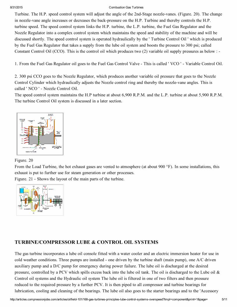
Turbine. The H.P. speed control system will adjust the angle of the 2ndStage nozzlevanes. (Figure. 20). The changein nozzlevane angle increases or decreases the backpressure on the H.P. Turbine and thereby controls the H.P.turbine speed. The speed control system links the H.P. turbine, the L.P. turbine, the Fuel Gas Regulator and theNozzle Regulator into a complex control system which maintains the speed and stability of the machine and will bediscussed shortly. The speed control system is operated hydraulically by the ' Turbine Control Oil ' which is producedby the Fuel Gas Regulator that takes a supply from the lube oil system and boosts the pressure to 300 psi; calledConstant Control Oil (CCO). This is the control oil which produces two (2) variable oil supply pressures as below :
1. From the Fuel Gas Regulator oil goes to the Fuel Gas Control Valve This is called ' VCO ' Variable Control Oil.
2. 300 psi CCO goes to the Nozzle Regulator, which produces another variable oil pressure that goes to the NozzleControl Cylinder which hydraulically adjusts the Nozzle control ring and thereby the nozzlevane angles. This iscalled ' NCO ' Nozzle Control Oil.The speed control system maintains the H.P turbine at about 6,900 R.P.M. and the L.P. turbine at about 5,900 R.P.M.The turbine Control Oil system is discussed in a later section.
Figure. 20From the Load Turbine, the hot exhaust gases are vented to atmosphere (at about 900 °F). In some installations, thisexhaust is put to further use for steam generation or other processes.Figure. 21 Shows the layout of the main parts of the turbine.
TURBINE/COMPRESSOR LUBE & CONTROL OIL SYSTEMS
The gas turbine incorporates a lube oil console fitted with a water cooler and an electric immersion heater for use incold weather conditions. Three pumps are installed one driven by the turbine shaft (main pump), one A/C drivenauxiliary pump and a D/C pump for emergency during power failure. The lube oil is discharged at the desiredpressure, controlled by a PCV which spills excess back into the lube oil tank. The oil is discharged to the Lube oil &Control oil systems and the Hydraulic oil system The lube oil is filtered in one of two filters and then pressurereduced to the required pressure by a further PCV. It is then piped to all compressor and turbine bearings forlubrication, cooling and cleaning of the bearings. The lube oil also goes to the starter bearings and to the 'Accessory
gear' of the turbine. After passing through these systems the lube oil returns to the lube oil reservoir. (Figure: 22)
Figure. 22
TURBINE HYDRAULIC OIL & TRIP SYSTEM
CONTROL OILA flow of oil to the accessory gear also goes to the FUEL GAS REGULATOR which is a device incorporating apump. This pump increases the oil pressure from 25 Psi to 300 psi which is called the Constant Control Oil (CCO). AVariable Control Oil (VCO) is also put out from the fuel gas regulator, the pressure of which depends on the signalcoming from the Turbine Speed Controller. This variable pressure oil (VCO) operates and controls the Fuel GasControl valve. The 300 psi CCO goes to the NOZZLE REGULATOR where another variable oil pressure is produced ( NCO ) Nozzle Control Oil, which passes through the 'NCO Dump' valve to the 2nd stage turbine, ( Load turbine ),nozzle control cylinder. This cylinder controls the variable angle nozzles which direct the superheated air leaving theHP turbine blades onto the blades of the load turbine. In this way the load turbine speed is controlled depending onthe load on the turbine produced by the driven machine. (Generator, Compressor…etc). A load change will tend tochange the turbine speed. The control system adjusts the angle of the L.P. turbine nozzlevanes to maintain the speed.The control system is interconnected to the Fuel Gas regulator and the HP & LP turbine control systems to maintainthe balance between the HP & LP turbines as mentioned earlier.
HYDRAULIC OILThe 120 Psi Hydraulic oil from the lube oil pump discharge is filtered by one of two filters and passes to thehydraulic oil system through a restriction orifice. The hydraulic oil is piped to :
1. A manual emergency trip valve2. The Solenoid trip valve3. The HP and LP turbine overspeed trips4. The NCO dump valve5. The Fuel gas stop valve
The system operates as follows: The pressure of the hydraulic oil is holding the NCO dump valve and the Fuel Gas Stop Valve (4 & 5 above), in the'GO' position The NCO dump valve is allowing the NCO to pass to the nozzle control cylinder. The fuel gas stopvalve is also held open to allow the fuel gas to flow to the combustion chambers. When any trip is activated, (1, 2 or3 above), the hydraulic oil pressure is dumped to the lube oil tank and drops to zero psi. This causes the Fuel GasStop valve to close shutting off the fuel to the combustion chambers. At the same time the NCO dump valve operates
to close the NCO supply and open the dump line from the control cylinder which takes the nozzle control ring to zerosetting (nozzles fully open). The turbine shuts down. The flow of hydraulic oil through the restriction orifice is lessthan the flow to the dump, keeping the pressure at zero. Before restarting the machine, speed controls have to be puton manual and set to zero, compressor recycles to manual and fully open and the trip condition has to be correctedand cancelled. As the trip condition is corrected and cancelled, the hydraulic pressure is restored slowly to normal andthe operating start up procedure followed to restart the machine. (Figure. 23)
CONTROL & HYDRAULIC TRIP SYSTEMSFigure. 23
Various trip conditions which will activate the electrical trip circuit to the solenoid valve include the following:
Low lube oil pressureLow seal oil overhead tank levelHigh shaft vibrationHigh temperature in the lube and seal oil return linesHigh compressor discharge temperatureHigh turbine exhaust temperatureHigh compressor suction drum liquid level etc.
The activation of any trip will dump the hydraulic oil to zero Psi and the oil will return to the lube oil reservoir.Before tripping the machine, the high turbine exhaust temperature operates to cut back the fuel to the machine whichof course reduces the machine capability. If this fails to cool the exhaust, the machine will trip. In very hot summerweather, particularly in hot climates, the high ambient temperature of the inlet air to the turbine air compressor causesthese conditions.
TURBINE OVERSPEED TRIP MECHANISMS
A turbine may exceed the safe speed for a number of reasons. One could be the failure of the speed control systems.Mainly however, overspeed is caused by a sudden drop in or loss of the load on the turbine. This, in the case of a gascompressor driven by the turbine, will occur if the gas supply to the machine is suddenly decreased or fails. Theresultant compressor surging due to the back and forth gas flow through the compressor does not allow the governorto control the correct speed quickly enough. The speed increases rapidly and the overspeed trip mechanism is activatedto shut down the machine by dumping the hydraulic oil and thereby closing the fuel gas stop valve. The operation ofthese mechanisms is graphically explained in the following Figures: 24 & 25.
In the above diagram, the turbine is at its operating speed and overspeed bolt is in the normal position inside its cavityin the shaft. The shuttle valve is held to the left against spring 'A' by the trip latch. The right end piston of the valve isclosing off the oil dump line, so holding the oil pressure between the two valve pistons. Hydraulic oil pressure is alsopassing to the Fuel Gas Stop Valve actuator, holding the valve open against spring 'B', allowing fuel to pass to theturbine. (A VERY SMALL leakage of oil is passing between the pistons and the cylinder walls of all trip systems toallow lubrication). OVERSPEED TRIP IN 'TRIPPED' CONDITION
Figure: 25
In this diagram, the turbine has exceeded the maximum speed and, due to the centrifugal force of rotation, theoverspeed bolt has moved outwards from the shaft cavity. The outward movement causes the bolt to strike the triplever and lift the trip latch, releasing the shuttle valve piston. Spring 'A' pushes the shuttle to the right which opensthe oil dump line. The hydraulic oil pressure immediately drops to zero, taking the pressure off the gas valve actuatordiaphragm. Spring 'B' pushes the diaphragm down closing the gas stop valve which instantly shuts down the turbine.(The oil pressure is also taken off all other trip systems being supplied). The sudden reduction in oil pressure to zerois due to the oil flow to dump being much higher than the supply oil flow through the restriction orifice in thehydraulic oil feed line; – look back at Figure: 23.
TURBINE COOLING SYSTEM(Figure. 26)In desert locations, cooling water is used as the heat absorbing medium for the lube oil cooler, the turbine shell,secondstage nozzle stems and the turbine support legs. The cooling water system is a 'Closed Loop' type in which thewater itself is cooled by an 'Airfin' cooler and recirculated around the system. The water temperature is maintainedat 100 to 110 °F. (This system is just like the cooling system in a car engine, on a very much larger scale). Two, A/Cmotor driven, centrifugal pumps are the primemovers for the cooling water one operating & one standby. A makeup head tank is incorporated into the system to maintain the necessary water volume and the suction head to the pumpto prevent cavitation. The discharge from the pumps at about 90 Psi is piped through check valves to feed the turbinesections as listed above. The water passes through the lube oil cooler tubes and returns to the airfin cooler to beginthe cycle again. On the outlet of the cooler, a thermostatic valve is installed which is controlled by the temperature ofthe lube oil header feeding the turbine bearings. A D/C driven, emergency pump is also installed in the turbine tosupply cooling to the turbine parts in the event of main pump failure, power failure or on low water pressure in theturbine shell cooling system. The emergency pump will run until the main pump is returned to operation or the shell
cooling is restored. (Total main pump failure will trip the turbine). A test valve is installed for checking the operationof the emergency pump. When the test valve is opened, pressure is dumped into the return line simulating a low waterpressure and a low pressure switch brings in the emergency pump. When the test valve is closed, pressure returns tonormal and the D/C pump will shut down again. The airfin water cooler has two motordriven fans. One is operatingduring normal weather conditions, the other will start on demand from the temperature control when watertemperature tends to rise above its set point. Fan High vibration and water low pressure alarms and shutdowns arealso incorporated. TURBINE COOLING SYSTEM
Figure. 26
TURBINE SYSTEM DETAILS
This explanation has been simplified as far as possible in order to make understanding of the system easier.
STARTING EQUIPMENTThe gas turbine is cranked for starting by an 'EXPANSION GAS TURBINE'. The starting turbine is connected to thegas turbine through the 'ACCESSORY GEAR' and a 'JAW CLUTCH’ The drive shaft of the starter turbine is splinedto receive the clutch hub. The driven hub of the clutch assembly is installed on one shaft of the accessory gear.
CONTROL SYSTEMThe gas turbine control system controls a complete power plant. The system utilises electrical and hydraulic deviceswhich regulate the flow of fuel gas to the combustion chambers and adjust the position of the variable angle secondstage nozzles. This in turn regulates the POWER and SPEED of the gas turbine. Various alarms and trips are installedto give alarm and/or shutdown should undesirable operating conditions arise.
THE FUEL GAS REGULATORThe FUEL GAS REGULATOR control system consists of THREE major inputs; Startup, Speed & Temperature.The outputs from these are fed into the Fuel Gas Regulator, where the input signal requiring the LEAST fuel takescontrol of the system. The OUTPUT of the Fuel Gas Regulator is a Constant Control Oil ('CCO') which is thenconverted to Variable Control Oil ('VCO') which will determine the fuel gas flow. CCO is also converted to anothervariable oil called Nozzle Control Oil ('NCO') that controls the 2nd stage variable nozzles through the NozzleRegulator and the Nozzle Control Cylinder.
See Figure. 27 below:SIMPLIFIED TURBINE CONTROL LOOP
Figure. 27
The FIRST input, is the STARTUP LOOP.While the Speed & Temperature inputs are CLOSED loops, the startup loop is OPEN. Two major inputs to the FuelRegulator are used during Startup.1. MANUAL SELECTOR SWITCH POSITION(Off, Crank, Fire, Accelerate and Run)2. STARTUP / TEMPERATURE PROGRAMME.The Manual Selector Switch is used to select predetermined values of VCO which, in turn, operate the gas controlvalve and controls the turbine startup.
The startup temperature control device, first suppresses the VCO to a limit which controls the EXHAUSTtemperature for a warmup of one minute, then, slowly removes this temperature suppression to accelerate the limitunder a controlled condition. Speed is controlled by an electric governor.
TEMPERATURE CONTROL LOOPThis control loop consists of the following components:
1. Twelve (12) exhaust thermocouples.2. Thermocouple averaging cabinet.3. MV/I (Millivolt to Milliamp) converter.4. Milliamp (MA) to PSI transducer. (I/P).5. Fuel Regulator Temperature Bellows.
The 12 thermocouples detect the turbine exhaust temperature and produce an average Millivolt signal. The Millivolt(MV) signal is converted to a Milliamp (MA) signal by the MV/I converter. This, in turn, is converted to a pneumatic(air) signal by the MA to PSI (I/P) transducer. This air signal then goes to the temperature bellows of the fuelregulator where it overrides the normal turbine control signal and reduces the VCO to the gas control valve. Thisdecreases the fuel and thereby decreases the exhaust temperature.
SPEED CONTROLAt 95% speed, the speed controller takes over and reduces fuel to ' Fullspeed, Noload ' value. The variable, 2ndstage nozzles are opened to high flow position.
LOADINGIn order to pick up load on the LP turbine, more fuel is admitted into the combustion chambers by a signal into thefuel regulator speed governor circuit. This in turn increases the VCO and opens the fuel gas control valve. At the
same time, the 2nd stage nozzles close down to control the speed of the HP turbine.
NORMAL SHUTDOWNThe machine loading is slowly decreased and the speed control brought down to minimum governor. The machine canthen be shut down by operating the manual trip lever or push button on the control panel. Check that auxiliary lubeoil system is operating.
EMERGENCY SHUTDOWNThis is carried out by operating the manual shutdowns as above. Again, check auxiliary lube oil system.
PROTECTION SYSTEMSThe gas turbine / driven machine systems are protected by a number of alarms and trips which will activate in theevent of an undesirable condition arising. The alarms will give warning of impending problems. Mechanical trips arethe LP & HP turbine overspeed trips and the Hydraulic Manual Trip Valve. Electrical trips will operate the solenoiddump valve and consist of :
High vibration tripLow lube oil pressureHigh lube oil temperatureHigh bearing temperatureCooling water failure or high temperaturePower failureFuel gas failure ... etc
If any of the mechanical or electrical trips operate, the hydraulic oil will dump and cause the fuel gas stop valve toclose. At the same time, the NCO will dump to return the 2nd stage nozzles to zero setting. Refer to the notes anddiagrams on the lube, control and hydraulic oil systems.
About the Author
Norrie is a retired professional who has been working in Oil and Gas and LNG production in MarsaelBrega, Libyafor 30 years.
Norrie used to be in the Training Dept. and prepared Programmes for Libyan Trainees.