44
Combustion of SRF: Technological Options and Operational Experience Kai Keldenich Dublin 20. October 2011

Combustion of SRF:
Technological Options and
Operational Experience
Kai Keldenich
Dublin 20. October 2011

25.09.2008 | EES_EBS_Verfahren_englisch.ppt Seite 2
STEAG group
STEAG Energy Services GmbH
General View
Current Projects
• Essential Waste to Energy Projects
• Refuse Derived Fuels (RDF) to Energy
• Biomass to Energy
10.06.2010 | Seite 3
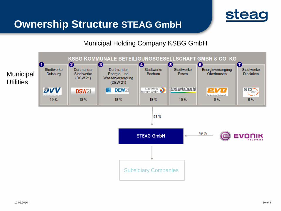
Ownership Structure STEAG GmbH
Municipal Holding Company KSBG GmbH
Municipal
Utilities
Subsidiary Companies

10.06.2010 | Seite 4
STEAG – Operations full of energy
Planning – operation – supply – marketing – recycling
… in Germany
and …
Project development,
planning, operation
and supply of power
plants…
… abroad … on the basis
of fossil…
… and
renewable
energy sources.
Marketing of
electricity and district
heat, and…
…recycling of power
plant byproducts.
Key figures (as of Dec. 2010)
External sales 2,762 € m Capital expenditure on fixed assets 163 € m Employees 4,916

10.06.2010 | Seite 5
STEAG State Power Inc.
The Business Area Energy
unites all energy activities
STEAG GmbH
RVG GmbH
STEAG-EVN Walsum 10
Kraftwerksgesellschaft mbH
STEAG New Energies GmbH
STEAG Energy Services GmbH
STEAG Fernwärme GmbH
STEAG Power Minerals GmbH
STEAG Trading GmbH
Iskenderun Enerji Üretim
ve Ticaret A.Ş.
Compania Electrica
de Sochagota S.A.

25.09.2008 | EES_EBS_Verfahren_englisch.ppt Seite 6
STEAG group
STEAG Energy Services GmbH
General View
Current Projects
• Essential Waste to Energy Projects
• Refuse Derived Fuels (RDF) to Energy
• Biomass to Energy
10.06.2010 | Seite 7
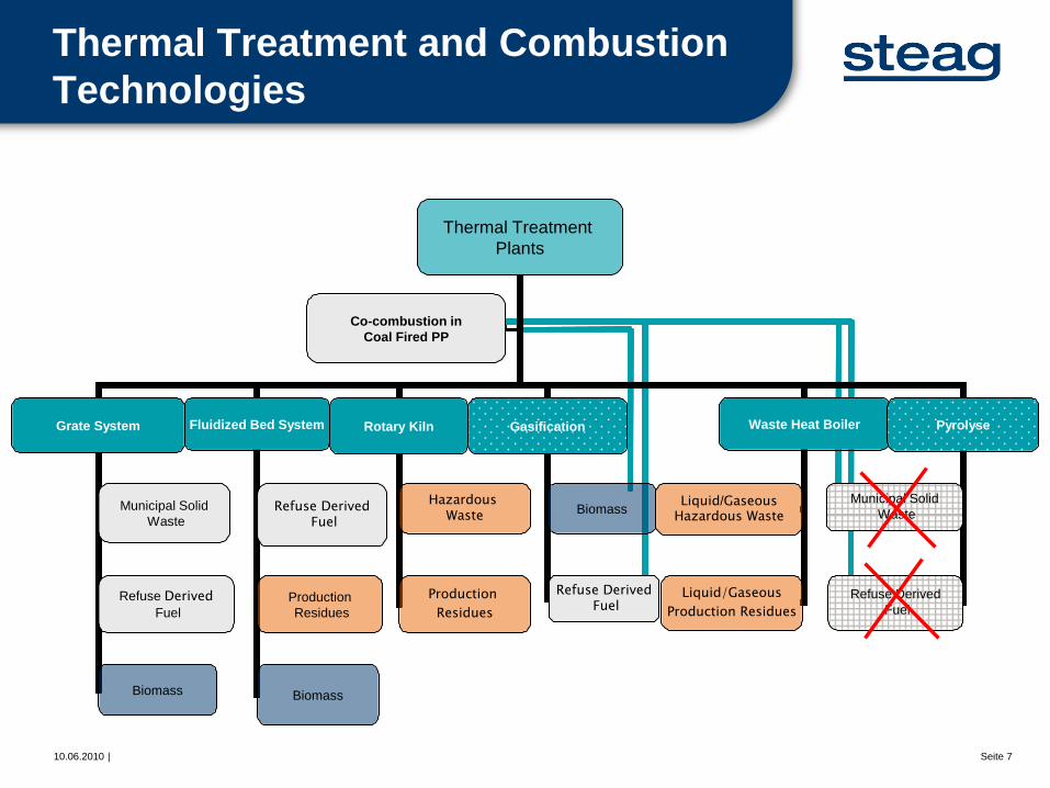
Thermal Treatment and Combustion
Technologies
Thermal Treatment
Plants
Grate System Fluidized Bed System Rotary Kiln Gasification Waste Heat Boiler
Hazardous Waste
Refuse Derived Fuel
Production
Residues
Municipal Solid
Waste
Refuse Derived
Fuel
Liquid/Gaseous Hazardous Waste
Liquid/Gaseous
Production Residues
Biomass
Co-combustion in
Coal Fired PP
Production
Residues
Biomass
Pyrolyse
Municipal Solid
Waste
Refuse Derived
Fuel
Refuse Derived Fuel
Biomass
10.06.2010 | Seite 8
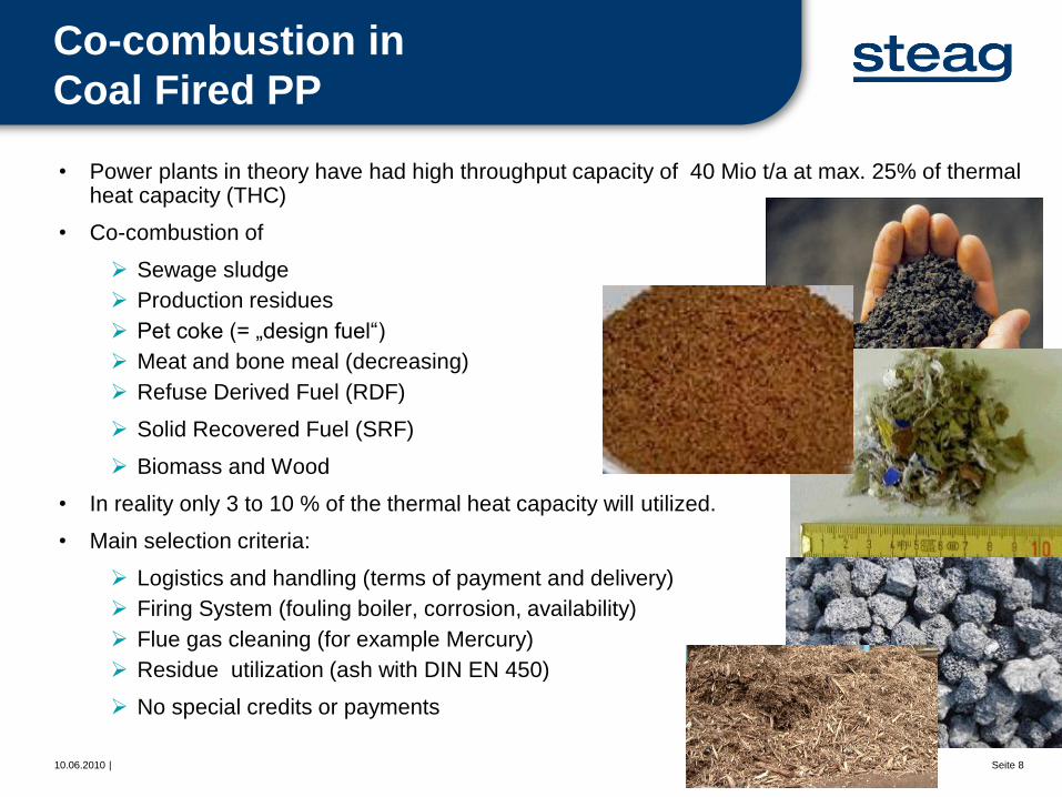
Co-combustion in
Coal Fired PP
• Power plants in theory have had high throughput capacity of 40 Mio t/a at max. 25% of thermal heat capacity (THC)
• Co-combustion of
Sewage sludge
Production residues
Pet coke (= „design fuel“)
Meat and bone meal (decreasing)
Refuse Derived Fuel (RDF)
Solid Recovered Fuel (SRF)
Biomass and Wood
• In reality only 3 to 10 % of the thermal heat capacity will utilized.
• Main selection criteria:
Logistics and handling (terms of payment and delivery)
Firing System (fouling boiler, corrosion, availability)
Flue gas cleaning (for example Mercury)
Residue utilization (ash with DIN EN 450)
No special credits or payments

10.06.2010 | Seite 9
Furnace Types
Grate Stoker Pulverized Coal
Combustion
Stationary Fluidized Bed Combustion Circulating Fluidized Bed Combustion

10.06.2010 | Seite 10
Furnace Types / Special Typ
Hazardous Waste
Rotary Kiln
Air-cooled / Water-cooled
Moving Grate Combustion

10.06.2010 | Seite 11
Boiler Technology
Grate System
Municipal Solid Waste Refuse Derived Fuel Biomass / Wood
industrial zone industrial zone municipal location industrial zone
power plant
Live steam parameters
400°C
40bar
Energy output
18 % electricity
with district heating
Live steam parameters
450 °C up to 525 °C
40 up to 90 bar
Energy output
20 up to 30 % electricity
with steam feed-in
Live steam parameters
450 °C up to 525 °C
40 up to 90 bar
Energy output
20 up to 30 % electricity
with steam feed-in
Live steam parameters
450 °C up to 525 °C
40 up to 90 bar
Energy output
20 up to 30 % electricity
with steam feed-in
10.06.2010 | Seite 12
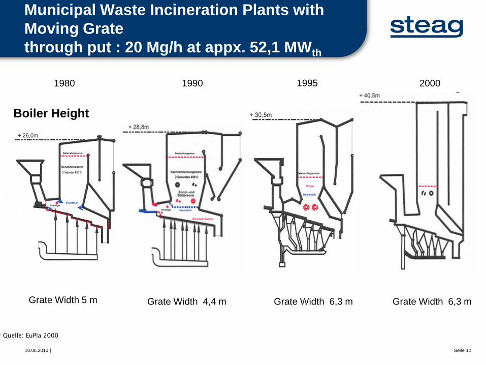
Municipal Waste Incineration Plants with
Moving Grate
through put : 20 Mg/h at appx. 52,1 MWth
1980 1990 1995 2000
Grate Width 5 m Grate Width 4,4 m Grate Width 6,3 m Grate Width 6,3 m
* Quelle: EuPla 2000
Boiler Height

10.06.2010 | Seite 13
Grate Typ
Waste and Biomass to Energy plant
Operating pressure 90 bar
Operating steam temperature 500 °C
Steam mass flow 126,5 Mg/h

10.06.2010 | Seite 14
Boiler Technology
Fluidized Bed
Municipal Solid Waste Refuse Derived Fuel Biomass / Wood
industrial zone industrial zone municipal location industrial zone
power plant
Live steam parameters
400°C
40bar
Energy output
18 % electricity
with district heating
Live steam parameters
450 °C up to 525 °C
40 up to 90 bar
Energy output
20 up to 30 % electricity
with steam feed-in
Live steam parameters
450 °C up to 525 °C
40 up to 90 bar
Energy output
20 up to 30 % electricity
with steam feed-in
Live steam parameters
450 °C up to 525 °C
40 up to 90 bar
Energy output
20 up to 30 % electricity
with steam feed-in

10.06.2010 |
Comparison of CFBC Boiler Layout
Alstom Lurgi Foster Wheeler Kvaerner

10.06.2010 | Seite 16
Live steam parameters and
corrosion mechanisms
Live steam parameters
450 °C up to 525 °C
40 up to 90 bar
Energy output
20 up to 30 % electricity
with reheater
35 %
Refuse Derived Fuel
Biomass / Wood
Municipal Solid
Waste

10.06.2010 | Seite 17
Main Steam Conditions and Fuel
Quality
VGB Forschungsprojekt Nummer 302, Untersuchung von Biomasse- und Altholzheizkraftwerken im Leistungsbereich von 5 bis 20 MWel
zur Verbesserung der Wirtschaftlichkeit (Teil I)
Liv
e S
team
Tem
pera
ture
[°C
]
Liv
e S
team
Pre
ssu
re
[bar]
Wood Fuel Quality
Steam Pressure [bar] Steam Temperature [°C]
Fluidized Bed Combustion hatched areas
natural wood

10.06.2010 | Seite 18
Reason for Stagnant Condition
Periods
VGB Forschungsprojekt Nummer 302, Untersuchung von Biomasse- und Altholzheizkraftwerken im Leistungsbereich von
5 bis 20 MWel zur Verbesserung der Wirtschaftlichkeit (Teil I)
fouling
heat recovery section
Corrosion / Erosion
fouling Furnace, first pass
grate, fluidized bed
fuel through put
ash handling
cleaning equipment
other subjects natural Wood
wood waste
number of namings limitting continuous operating period

10.06.2010 | Seite 19
Chlorine Induced Active Oxidation
Corrosion Mechanism
Modell der Korrosionsvorgänge unter Belägen [Born, 2004]
Boiler super heater tube (T = 400…550°C)
fouling of eutectic mixture vapor diffusion of flue gas components
fouling of ashes and aerosols mixture
flue gas : NaCl, KCl, HCl, O2, SO2
fly ash fouling
Chlorine-cycle
Iron-Cycle
pastry Fe3O4
molten salt
(if necessary carbon within)

10.06.2010 | Seite 20
Corrosion Diagram Waste to Energy
Plant
SH1
SH2
SH3
Flue Gas Temperature °C
Outs
ide T
ube S
urf
ace T
em
pera
ture
°C
Corrosion
possible
corrosion
free from
corrosion

10.06.2010 | Seite 21
Fuel composition and fouling
structure on boiler tube

10.06.2010 | Seite 22
Combustion Model
Centre Flow Combustion
Excess Fuel Zone
Burnout Zone
SA SA
PA
Oxygen Rich Zone
Release of
Volatile
Chlorine Compounds
Alkaline chloride
Alkaline earth chloride
Heavy metal chloride
Reaction with SOx , O2 ,, if
Efficient Turbulence and
residence time
Release of
Sulfur di- and trioxide
and
Alkaline
10.06.2010 | Seite 23
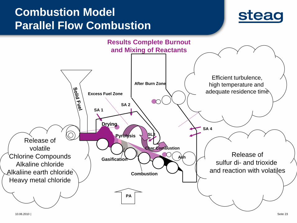
Combustion Model
Parallel Flow Combustion
Release of
volatile
Chlorine Compounds
Alkaline chloride
Alkaliine earth chloride
Heavy metal chloride
Release of
sulfur di- and trioxide
and reaction with volatiles
Results Complete Burnout
and Mixing of Reactants
Oxygene Rich Zone
After Burn Zone
SA 4
SA 1
PA
Excess Fuel Zone
Ash
Char Combustion
Drying
Combustion
Pyrolysis
Gasification
SA 2
SL3
Efficient turbulence,
high temperature and
adequate residence time

10.06.2010 | Seite 24
Corrosions number II
0,000
0,050
0,100
0,150
0,200
0,250
0,300
0,350
0,400
0,450
0,100 1,000 10,000 100,000
Alkali potential
Chlo
rine c
onte
nt
in F
uel [%
]
Coal/Wood
Plant residues
Lahti
Bexbach
Ensdorf
Infracor+
Altholz
Infracor
BMK Lünen
Miscanthus (it)Hirse
SchilfGerstenstroh
KenafWeizenstroh
Miscanthus (de)
Raps
KanariengrasFlachsstroh
FlachsschnittFichtenrinde
Waldholz chips
corrosion-endangered
Lahti+
Vergaser+
Chlor
Lahti Kohle
Lahti+
Vergaser
Alkali potential on fuel

25.09.2008 | EES_EBS_Verfahren_englisch.ppt Seite 25
STEAG group
STEAG Energy Services GmbH
General View
Current Projects
• Essential Waste to Energy Projects
• Refuse Derived Fuels (RDF) to Energy
• Biomass to Energy

10.06.2010 | Seite 26
Waste to Energy
Waste throughput Mg/a 225.000
Combustion units unit‘s 2
Thermal heat throughput (per unit) MWth 37,5
Waste throughput (per unit) Mg/h 15
Design calorific value (Hu) MJ/kg 9,0
Calorific value range (Hu) MJ/kg 7 - 12
Power output MWel ca. 20
Plant power consuption MWel ca. 4
Waste bunker capacity m³ ca. 11.000
T.A. Lauta
Essential Plant Data

10.06.2010 | Seite 27
Waste to Energy
T. A. Lauta Flow Diagram
Unloading
area
Boiler house
Water
Turbine
Ash handling
facility
Lime silo
Compressed
air
Activated coke
Storage facility
Air-cooled
condenser
Unit
transformer
Dry
Scrubber
ID Fan
Activated
coke filter
Fabric Filter
Reaction
products
Residual silo for
reaction products
Activated
coke milling
Steam
gas heater DeNOx
plant Stack
Recirculation
silo
Generator
Turbine
house
Waste bunker

10.06.2010 | Seite 28
Thermal Waste to Energy Plant Lauta

25.09.2008 | EES_EBS_Verfahren_englisch.ppt Seite 29
STEAG group
STEAG Energy Services GmbH
Current Projects
• Essential Waste to Energy Projects
• Refuse Derived Fuels (RDF) to Energy
• Biomass to Energy

10.06.2010 | Seite 30
RDF to Energy, EVA Höchst,
Infraserv Frankfurt
• Industriepark Höchst, Frankfurt
Site for chemicals, pharmaceuticals and biotechnology
• RDF-ICFB Combustion with capacity of 700.000 t/a
• 3 times 94 MW (thermal)
• 80 MW (electricity)
• Japanese EPC
• trial operation
at present

10.06.2010 | Seite 31
RDF / Waste Utilisation
Infraserv Frankfurt
Delivery Delivery bunker boiler house
closed
delivery hall RDF
in put
bubbling
fluidized
bed boiler
lime-spray
drying
RDF
fabric
filter
combustion air
steam turbine and generator
flue gas treatment
entrained
flow
reactor
i-d fan,
stack
bed material
steam
fly ash
electricity
reaction product
cyclon
economizer

10.06.2010 | Seite 32
ICFB Combustion of Refuse derived
fuel; Infraserv Frankfurt
Internal Circulating Fluidised Bed
Combustion with Combustion insite the
Boiler
Stable Technology – without moving parts
inside the Furnace
wide range in respect of calourific value of
fuel and waste
Efficient in-bed heat-transfer
Recycling of metalls like iron, steal and
non-ferrous metals

25.09.2008 | EES_EBS_Verfahren_englisch.ppt Seite 33
STEAG group
STEAG Energy Services GmbH
Current Projects
• Essential Waste to Energy Projects
• Refuse Derived Fuels (RDF) to Energy
• Biomass to Energy

10.06.2010 | Seite 34
STEAG New Energies Biomass to Energy Plants
Plant Start up Wood Fuel Through put (Mg/a)
Power out
put (MWel)
District heating
out put (MWth)
Großaitingen 2002 A I - A III 45.000 5 -
Buchenbach 2002 AI – AII 30.000 1,2 3,3
Neufahrn 2003 A I - A III 45.000 5,3 10
Werl 2003 A I - A II 10.000 0,48 3,3
Buchen 2004 A I - A IV 60.000 7,1 10
Dresden 2004 A I - A IV 55.000 7,1 10
Neuwied 2004 A I - A IV 65.000 7,6 18
Traunreut 2004 A I - A III 50.000 5 11
Ilmenau 2005 A I - A III 45.000 5,3 10
Lünen 2006 A I - A IV 140.000 20 -
Warndt 2009 Forest wood 40.000 1,8 8
Total amount - A I - A IV 595.000 66 84

10.06.2010 | Seite 35
Brennstoffcharakterisierung Altholz
Fuel Quality Waste Wood
• Grain Size Distribution:
High fuel fines increased fouling; risk of fuel segregation
• Ash and Minerals:
All-important for abrasion of mechanical handling equipment, for high disposal
cost and for high corrosion potential
• Chlorine Content:
Risk of high temperature Chlorine corrosion; low ash softening temperature
• Calorific Value:
Define the fuel amount and fuel cost
• Air distribution and burn out phase:
Variable fuel will have variably burn out and different air distribution must be
possible

10.06.2010 | Seite 36
Summary
Waste to Energy and Renewable Energies
• Energy from waste and biomass is state of the art, but
technology of biomass to energy plants has to adapt to
the different fuel qualities.
• Energy contracting and delivery for industry and real
estate helps to environmental relief and reduction in
energy costs.
• Fuel with different qualities leads, depending on fuel
treatment extent and chemical composition, make
changes at combustion system necessary.
• Control and regulate of the combustion and air
distribution must be possible.
• High performance factors together with high plant
availability rate shall be noted .

10.06.2010 | Seite 37
Take advantage of the potential of an
interdisciplinary engineering company
STEAG Group specializes in the engineering and O&M management of waste and
biomass plants, focusing on thermal energy generation facilities for municipal solid
wastes, biomass, refuse-derived fuels and energy sources of the future.
Project Development
Project Planning and Engineering
Permitting Management
Project Management
Site Supervision / Commisioning
Plant Operation
Plant Optimization


10.06.2010 | Seite 39
Specific Boiler Design
Super Heater at high Flue Gas Zone
Schematic diagram of Maribo Sakskøbing
CHP Plant showing position of
superheater sections investigated.
The arrows show the flow for the banks 2-7 in
superheaters 2 and 3.
Corrosion Investigations at Maribo Sakskøbing
Combined Heat and Power Plant Part IV
Melanie Montgomery et.al. ; April 2007

10.06.2010 | Seite 40
RDF and Biomass to Energy Plants

10.06.2010 | Seite 41
Chemistry of Potassium, Sodium,
Zinc and Chlorine
Chlorine compounds at reducing and oxidizing conditions for the case Cl/Zn = 11. Remaining chlorine (80%–90%) was found in the flue gas mainly as hydrogen chloride.
When chlorine is present at lower concentrations than potassium, it reacts with potassium and forms solid potassium chloride which starts to volatilize at 500 °C. At 700 °C potassium chloride is completely volatilized and present in the flue gas.
Anna-Lena Elled, Lars-Erik Åmand, David Eskilsson
Energy & Fuels 2008, 22, 1519–1526

10.06.2010 | Seite 42
Corrosion number S/Cl Ratio
0,0
0,1
0,2
0,3
0,4
0,5
0,6
0,7
0,8
0,00 0,05 0,10 0,15 0,20
Chlorine in Fuel [mol/kg TS]
Sulp
hur
in F
uel [m
ol/
kg T
S]
Fuel german hard coal
Energy plant
imported coal
Lahti
S/Cl = 4
without corrosion
Infracor K4Infracor K4
+ AltholzEnsdorf
Bexbach
BMK Lünen
Göttelb.
firs brushwood
cottonwoodoatgrop
Coal
Lahti
rape
S/Cl = 2
corrosion-endangered
Sulfur / Chlorine ratio

10.06.2010 | Seite 43
Waste to Energy
Essential Waste to Energy Plants of STEAG-Group
with participation in build, finance and operation management
Plant Start up Through put
(Mg/a)
Performance STEAG-Group
RZR Herten 1982 250.000 (1)
60.000 (2)
design, operation
MHKW Burgkirchen 1994 200.000 design, operation
AVA Augsburg 1994 220.000 design, build, operation, finance
AEZ Kreis Wesel 1997 250.000 design, build, operation, finance
AVA Velsen 1997 210.000 operation
MHKW Pirmasens 1998 170.000 design, build, operation, finance
AHKW Neunkirchen
(Neubau)
2001 120.000 design, build, operation, finance
MVA Madeira 2002 130.000 operation
T.A. Lauta 2004 225.000 design, build, operation, finance
TREA Breisgau 2005 150.000 design, build, operation, finance
(1) municipal solid waste (2) hazardous waste

10.06.2010 | Seite 44
Waste derive wood fraction
Monitoring zur Wirkung der Biomasseverordnung auf Basis des Erneuerbare-Energien-Gesetzes (EEG), Forschungs- und Entwicklungsvorhaben 201 41 132, Institut für Energetik & Umwelt gGmbH (IE), Leipzig, 17. Dez. 2003
minicipal solid
waste
valuable material
recycling
industrial waste
bulky waste
construction &
demolition waste
industrial
residual wood
wood part in waste stream
wood waste
waste management wood waste outside
waste management
state-owned municipalities / waste disposal enterprise
treatment and
sorting plant
disposal facility
utilization & recycling
biomass to energy
sort
residues
waste disposal
landfill
waste disposal
landfill
waste disposal
waste to energy


