1 Dharam V. Punwani President, Avalon Consulting, Inc. Combustion Turbine Inlet Cooling (CTIC) for Power Augmentation: An Overview Presented at ASME Turbo Expo Vancouver, BC, Canada June 6-10, 2011
Transcript
1
Dharam V. Punwani
President, Avalon Consulting, Inc.
Combustion Turbine Inlet Cooling (CTIC) for Power Augmentation: An Overview
Presented at
ASME Turbo Expo
Vancouver, BC, Canada
June 6-10, 2011
2
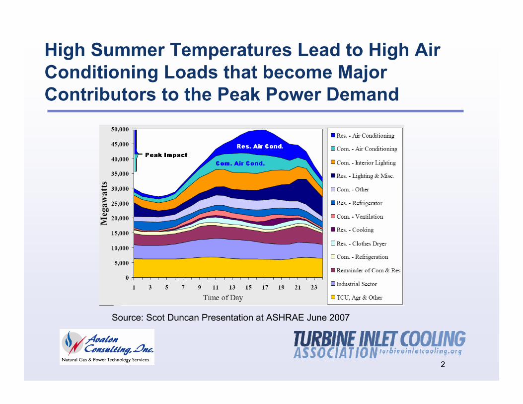
High Summer Temperatures Lead to High Air Conditioning Loads that become Major Contributors to the Peak Power Demand
Source: Scot Duncan Presentation at ASHRAE June 2007
3
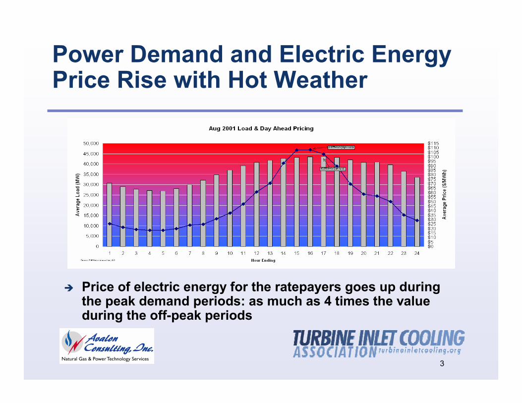
Power Demand and Electric Energy Price Rise with Hot Weather
Price of electric energy for the ratepayers goes up during the peak demand periods: as much as 4 times the value during the off-peak periods
4
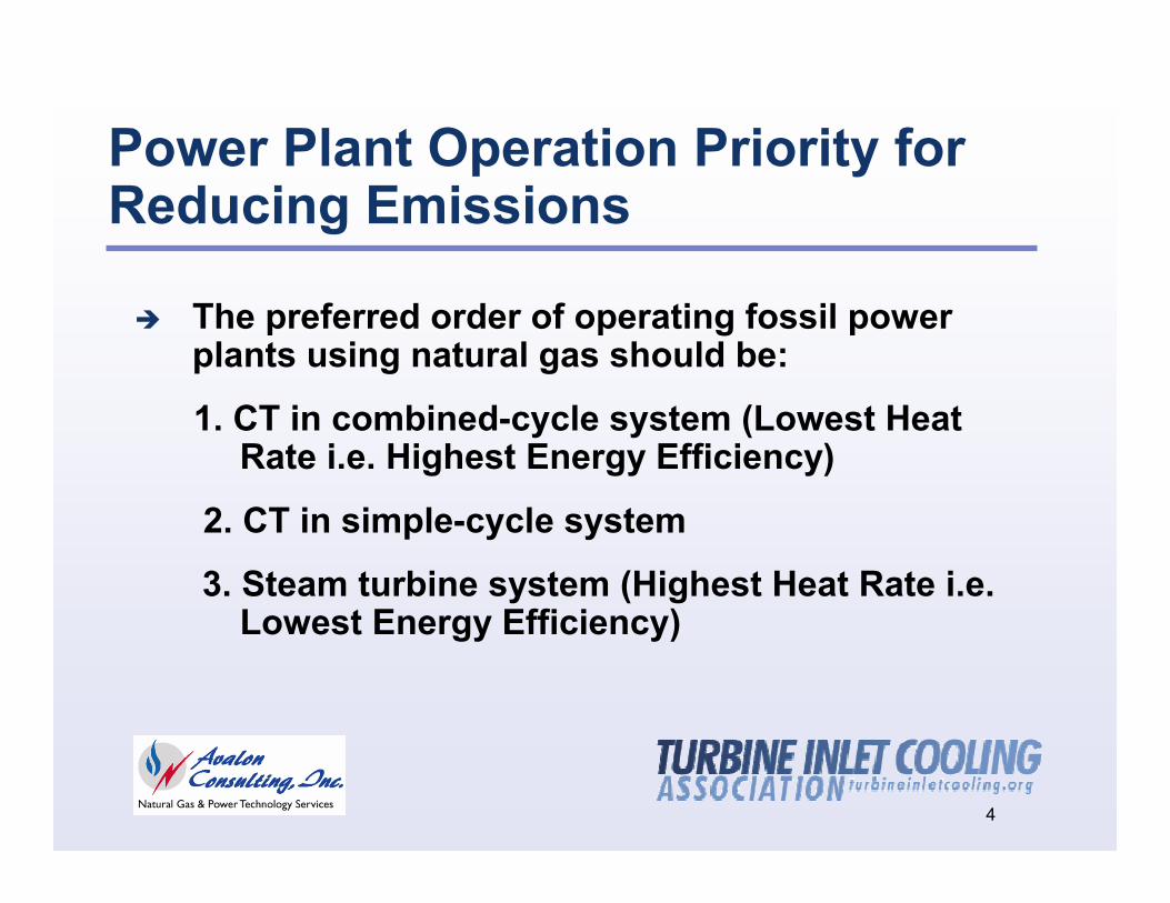
Power Plant Operation Priority for Reducing Emissions
The preferred order of operating fossil power plants using natural gas should be:
1. CT in combined-cycle system (Lowest Heat Rate i.e. Highest Energy Efficiency)
2. CT in simple-cycle system
3. Steam turbine system (Highest Heat Rate i.e. Lowest Energy Efficiency)
5
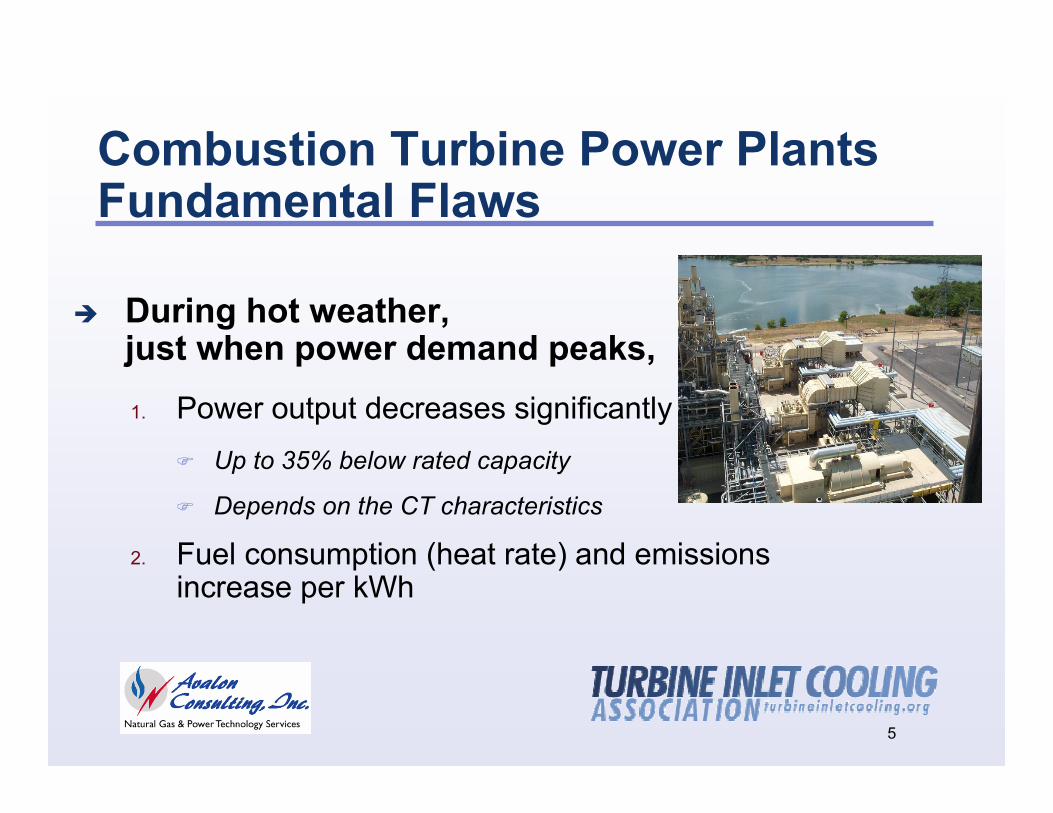
Combustion Turbine Power PlantsFundamental Flaws
During hot weather, just when power demand peaks, 1. Power output decreases significantly
Up to 35% below rated capacity
Depends on the CT characteristics
2. Fuel consumption (heat rate) and emissions increase per kWh
6
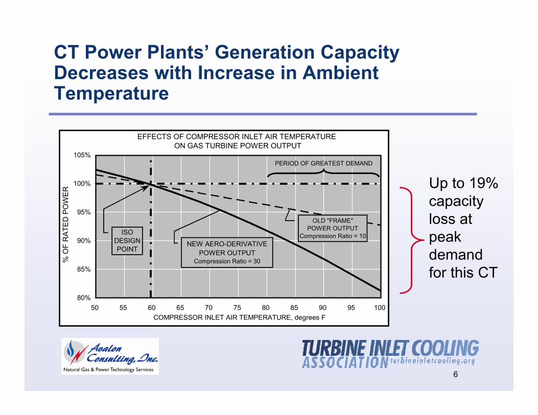
CT Power Plants’ Generation Capacity Decreases with Increase in Ambient Temperature
EFFECTS OF COMPRESSOR INLET AIR TEMPERATURE ON GAS TURBINE POWER OUTPUT
80%
85%
90%
95%
100%
105%
50 55 60 65 70 75 80 85 90 95 100COMPRESSOR INLET AIR TEMPERATURE, degrees F
% O
F R
ATE
D P
OW
ER
OLD "FRAME"POWER OUTPUT
Compression Ratio = 10
PERIOD OF GREATEST DEMAND
NEW AERO-DERIVATIVE POWER OUTPUT
Compression Ratio = 30
ISO DESIGN POINT
Up to 19% capacity loss at peak demand for this CT
7
0.3
0.4
0.5
0.6
0.7
0.8
0.9
1
12:00
AM2:0
0 AM
4:00 A
M6:0
0 AM
8:00 A
M10
:00 AM
12:00
PM2:0
0 PM
4:00 P
M6:0
0 PM
8:00 P
M10
:00 PM
SCE
PG&E
SDG&E
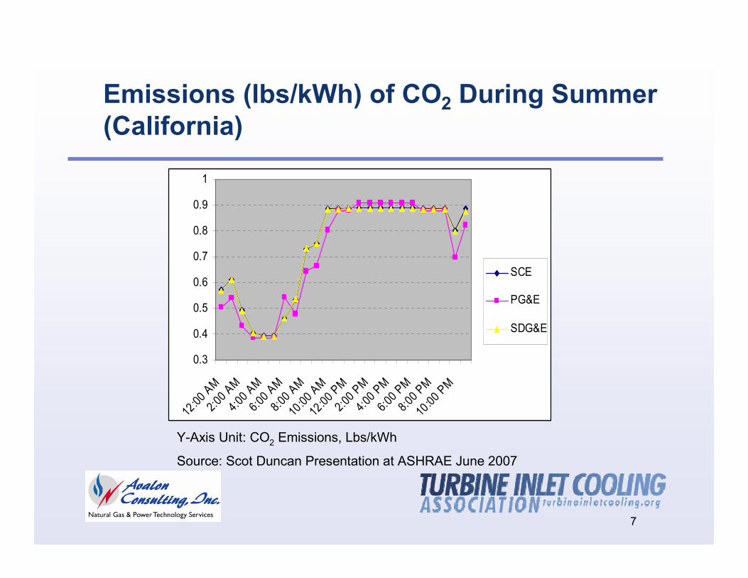
Emissions (lbs/kWh) of CO2 During Summer (California)
Y-Axis Unit: CO2 Emissions, Lbs/kWh
Source: Scot Duncan Presentation at ASHRAE June 2007
8
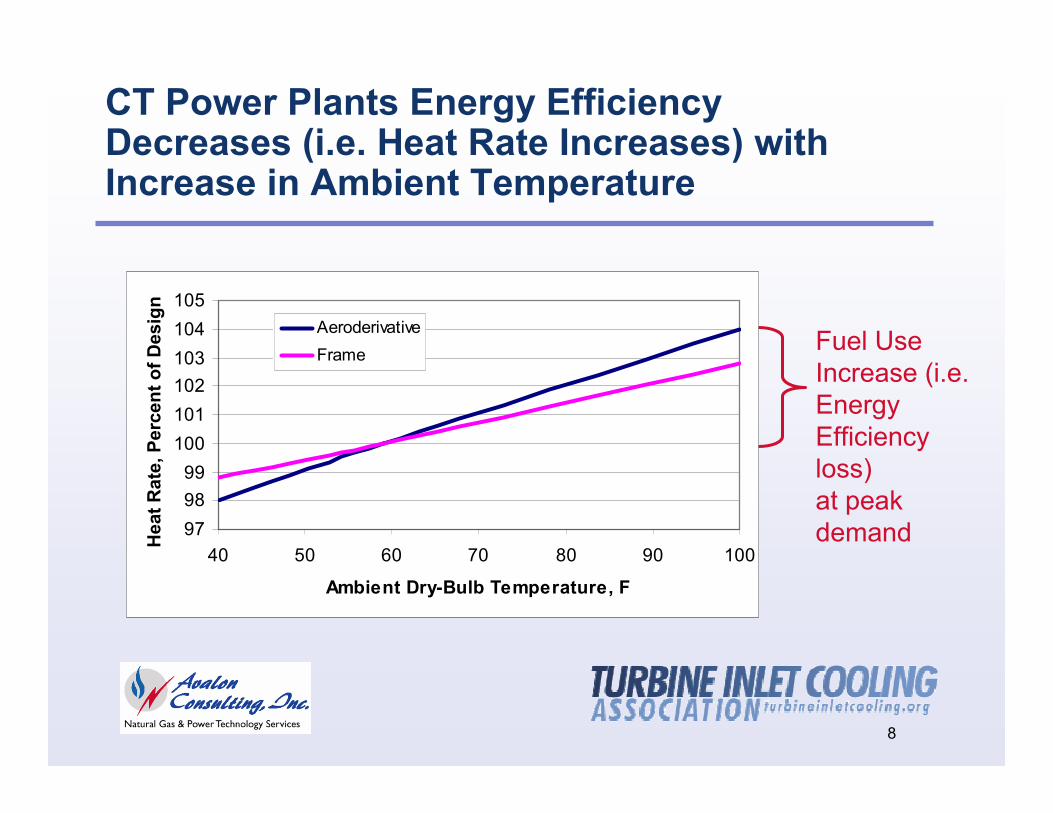
Fuel Use Increase (i.e. Energy Efficiency loss) at peak demand
CT Power Plants Energy Efficiency Decreases (i.e. Heat Rate Increases) with Increase in Ambient Temperature
979899
100101102103104105
40 50 60 70 80 90 100
Ambient Dry-Bulb Temperature, F
Hea
t Rat
e, P
erce
nt o
f Des
ign
AeroderivativeFrame
9
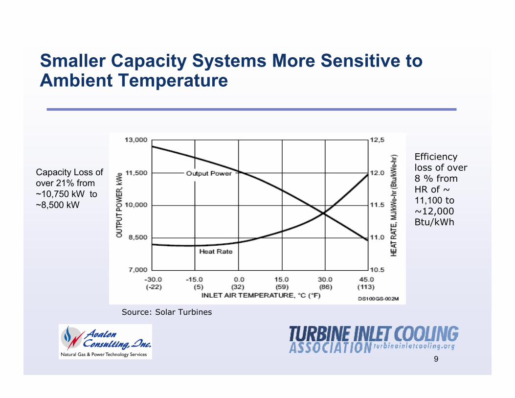
Smaller Capacity Systems More Sensitive to Ambient Temperature
Source: Solar Turbines
Capacity Loss of over 21% from ~10,750 kW to ~8,500 kW
Efficiency loss of over 8 % from HR of ~ 11,100 to ~12,000 Btu/kWh
10
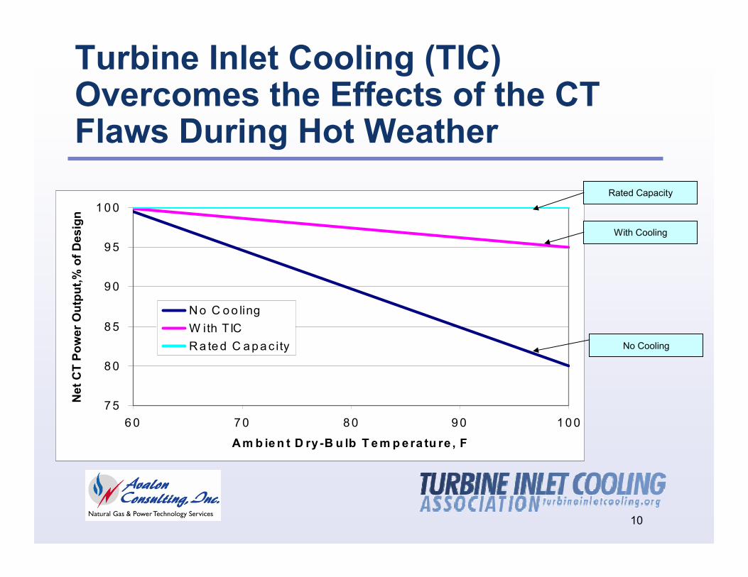
Turbine Inlet Cooling (TIC)Overcomes the Effects of the CT Flaws During Hot Weather
7 5
8 0
8 5
9 0
9 5
1 0 0
6 0 7 0 8 0 9 0 1 0 0
A m b ie n t D ry -B u lb T e m p e ra tu re , F
Net
CT
Pow
er O
utpu
t,% o
f Des
ign
N o C o o lingW ith TIC R a te d C a p a c ity
With Cooling
Rated Capacity
No Cooling
11
Turbine Inlet Cooling Environmental Benefits
Reduces the need for operating inefficient and higher-emission power plants and thus,
Reduces emissions of pollutants (SOx, NOx, particulates)
Reduces emissions of green house gas (CO2)
Minimizes, delays, or even eliminates the need for new plants
12
Turbine Inlet Cooling (TIC) Reduces Need for New Power Plants
Implementing TIC on combustion turbines in combined-cycle (CC) systems effectively displaces/reduces operations of combustion turbines in simple-cycle (SC) systems
TIC for each nominal 500 MW CC plant eliminates the need for a nominal 40-50 MW SC peaker and its associated siting, emissions, interconnection and other issues
13
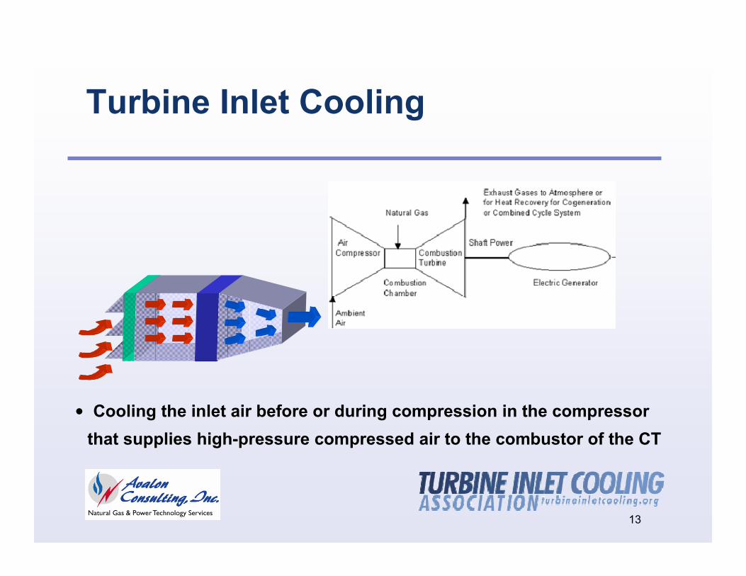
Turbine Inlet Cooling
• Cooling the inlet air before or during compression in the compressor that supplies high-pressure compressed air to the combustor of the CT
14
TIC Technologies
Two Categories
Reduce Temperature of the Inlet Air Entering the Compressor
Reduce Temperature of the Inlet Air During Compression
15
TIC Technologies
Reducing Inlet Air Temperature
Direct Evaporation: Wetted Media, Fogging
Indirect Evaporation
Chilled Fluid: Indirect Heat Exchange, Direct Heat exchange
Chilled Fluid in TES: Full-Shift and Partial-Shift
LNG Vaporization
Hybrid: Some combination of two or more cooling technologies
16
TIC Technologies
Reducing Inlet-Air Temperature During Compression
Wet Compression (or Fog Overspray)
17
Turbine Inlet Cooling (TIC) Technologies are Simple and Proven
Thousands of plants already benefiting from TIC
TICA web site database of 100+ plants worldwide
18
TIC TechnologyCT Design and CharacteristicsWeather Data (dry-bulb and coincident wet-bulb temperatures) for the Geographic Location of the CTDesign Ambient ConditionsDesign Cooled Air Temperature (if allowed by the TIC technology)
Factors Affecting the Capacity Enhancement Potential of TIC
19
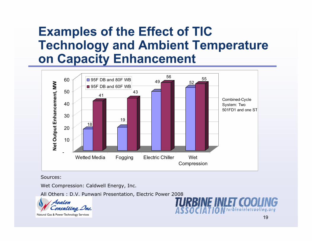
Examples of the Effect of TIC Technology and Ambient Temperature on Capacity Enhancement
Sources:
Wet Compression: Caldwell Energy, Inc.
All Others : D.V. Punwani Presentation, Electric Power 2008
18
41
19
43
4956
5255
-
10
20
30
40
50
60
Net
Out
put E
nhan
cem
ent,
MW
Wetted Media Fogging Electric Chiller WetCompression
95F DB and 80F WB95F DB and 60F WB
Combined-Cycle System: Two 501FD1 and one ST
20
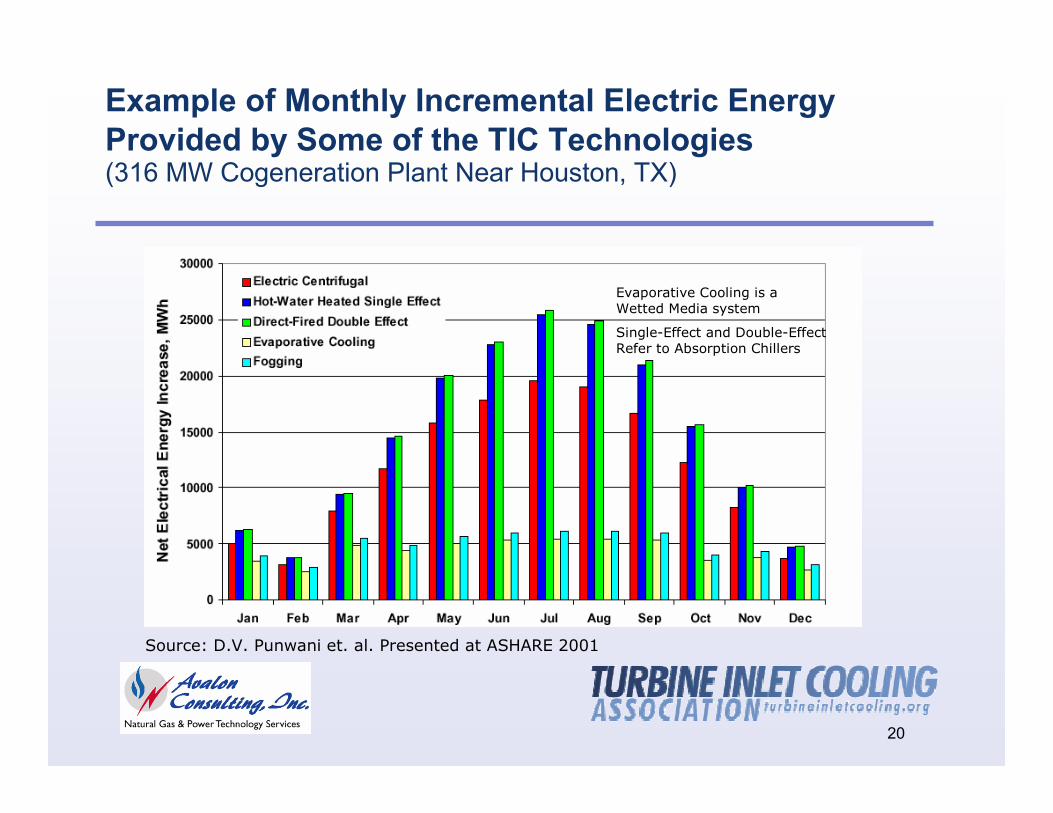
Example of Monthly Incremental Electric Energy Provided by Some of the TIC Technologies(316 MW Cogeneration Plant Near Houston, TX)
Source: D.V. Punwani et. al. Presented at ASHARE 2001
Evaporative Cooling is a Wetted Media system
Single-Effect and Double-Effect Refer to Absorption Chillers
21
Factors Affecting the Economics of TIC
TIC Technology
CT Characteristics
Weather Data for the Geographic Location of the CT
Market Value of the Additional Electric Energy Produced
Fuel Cost
22
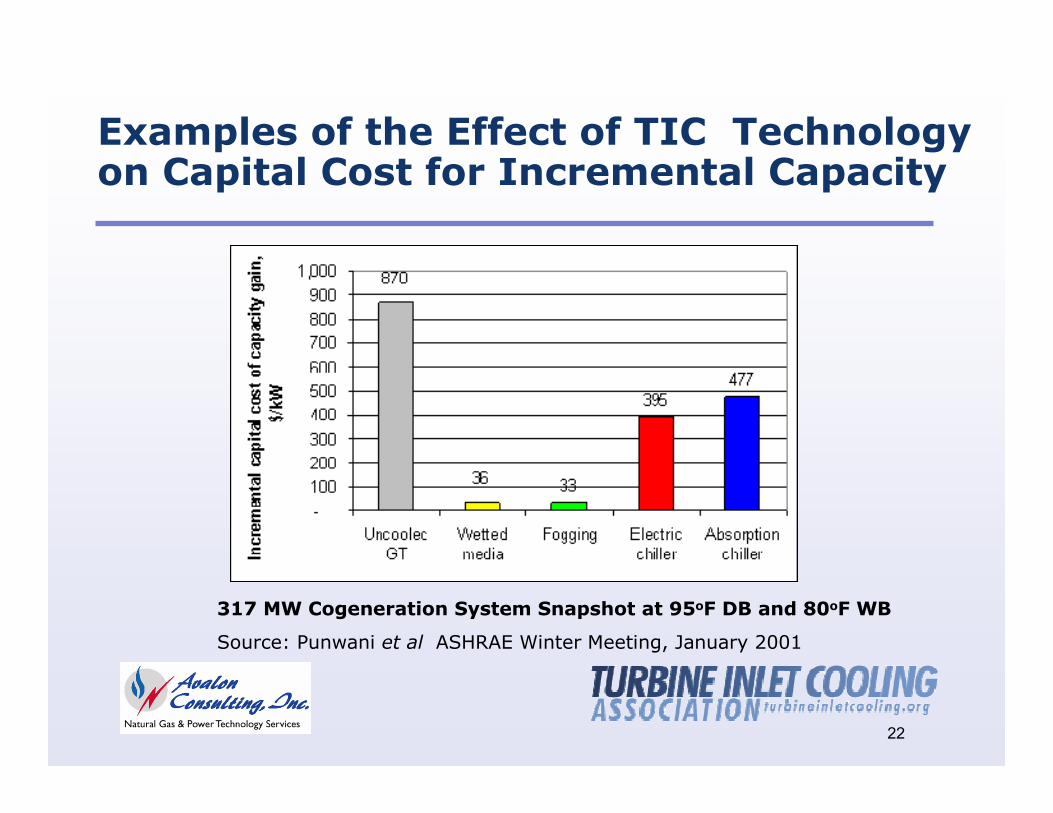
Examples of the Effect of TIC Technology on Capital Cost for Incremental Capacity
317 MW Cogeneration System Snapshot at 95oF DB and 80oF WB
Source: Punwani et al ASHRAE Winter Meeting, January 2001
23
Turbine Inlet CoolingEconomic Benefits
Generates more MWh and revenue during peak demand periods when electric energy value and price are high
Reduces capital cost per unit of the increased generation capacity compared to new power plants
Reduces cost of electric energy generation compared to the low energy efficiency “peakers”
Reduces cost for ratepayers by allowing lower capacity payments by the independent system operators (ISOs) to power producers
24
Suggested Changes To Regulatory Structure
Realize full potential of existing combustion turbines plants
Require addition of TIC before allowing new plants to be built
Exempt TIC from environmental re-permitting
Impact of TIC is similar to ambient temperature naturally going down during winter (i.e. TIC yields winter performance in summer)
Calculate capacity payments for plant owners on the basis of systems incorporating TIC
Consistent with the PJM affidavit made to the FERC in August 2005
25
TIC Summary
Significantly Increases CT power output during hot weather
Multiple options of commercially-proven technologies are available
Generally economically attractive to the plant owners and rate payers, rate payers and plant owners
Helps reduce emissions and thus, good for the environment
Good for the environment, rate payers and the plant owners