PDA 06/2005 Care has been taken to ensure that the contents of this publication are accurate, but Tegral Metal Forming Ltd. and its related companies do not accept responsibility for errors or for information which is found to be misleading. Suggestions for, or descriptions of the end use or application of products or methods of working are for information only and Tegral Metal Forming Ltd. and its related companies accept no liability in respect thereof. Before using products supplied or manufactures by Tegral Metal Forming Ltd. and its related companies, the customer should satisfy himself/herself of their suitability. Copyright 2005 Tegral Metal Forming Ltd. Athy, Co. Kildare, Ireland. Tel: 00 + 353 (0) 59 86 31619 Fax: 00 + 353 (0) 59 86 40701 www.tegral.com an GROUP company Floor Decking, Roof Decking, Purlins & Rails Designer’s Structural Products Guide
Transcript
PDA 06/2005
Care has been taken to ensure that the contents of this publication are accurate, but Tegral Metal Forming Ltd. and its related companies do not accept responsibility forerrors or for information which is found to be misleading. Suggestions for, or descriptions of the end use or application of products or methods of working are for
information only and Tegral Metal Forming Ltd. and its related companies accept no liability in respect thereof. Before using products supplied or manufactures by TegralMetal Forming Ltd. and its related companies, the customer should satisfy himself/herself of their suitability.
DESIGNER’S STRUCTURAL PRODUCTS GUIDE Using the GuideDESIGNER’S STRUCTURAL PRODUCTS GUIDE Introduction
21
A world of experience
Our PartnersThrough a long-standing partnership withCorus, a world-renowned manufacturer of steel and aluminium, Tegral customersand specifiers are assured of the higheststandards and quality in all Tegral products.
Our StandardsAll manufacturing in Athy meetswith the stringent requirements of Quality Assurance systems to ISO 9001:2000.
Our PeoplePeople really do matter at Tegral MetalForming. Recently the company proudly
embraced and succeeded inachieving the “Excellence ThroughPeople” award, Ireland’s nationalstandard for human resource development.
Our Industry AssociatesTegral Metal Forming takes an active rolein the promotion of the metal industry andis involved in the Roof Manufacturers andSuppliers Association (RMSA) in Ireland,the Metal Cladding and RoofingManufacturers Association (MCRMA) in the UK and also the Irish Farm Buildings Association.
Our CompanyTegral Metal Forming is part of the Tegral
Group and a subsidiary of the Etex Group, aworld-renowned international building
products company. For over 25 years, Tegral Metal Forming has been to the
forefront of development with regard toroofing, cladding and flooring systems.
Based in Athy, Co. Kildare, the Tegral Groupconsists of Tegral Building Products and
Tegral Metal Forming. Tegral BuildingProducts is Ireland’s largest manufacturer
and distributor of roofing products andTegral Metal Forming Ltd. is a leading
manufacturer and supplier of metal roofingand flooring systems for the construction
industry.
The comprehensive product range isdesigned to suit most applications in
modern commercial, industrial andagricultural construction. Over the years,Tegral Metal Forming has developed an
expertise in every aspect of metal systemsapplication.
Project: The Pavilions Shopping Centre, Swords, DublinArchitects: OMS Architects
This guide covers the key elements,issues and considerations the designer
faces when selecting structuralproducts. Tegral Metal Forming offersmetal applications that include floor
decking, roof decking, purlins & rails.The product range is extensive,
innovative and of superior quality. This is strongly supported by a
professional team of technical servicesexperts available to assist the designer
in the process.
Our guiding principles are objectivityand professionalism, our goal is to helpour customer find the right solutionand our commitment to quality andexcellence in everything we do, remains constant.
For further technical information on allTegral products, please contact ourTechnical Services Department: Tel: 059 86 40750 Email: [email protected]
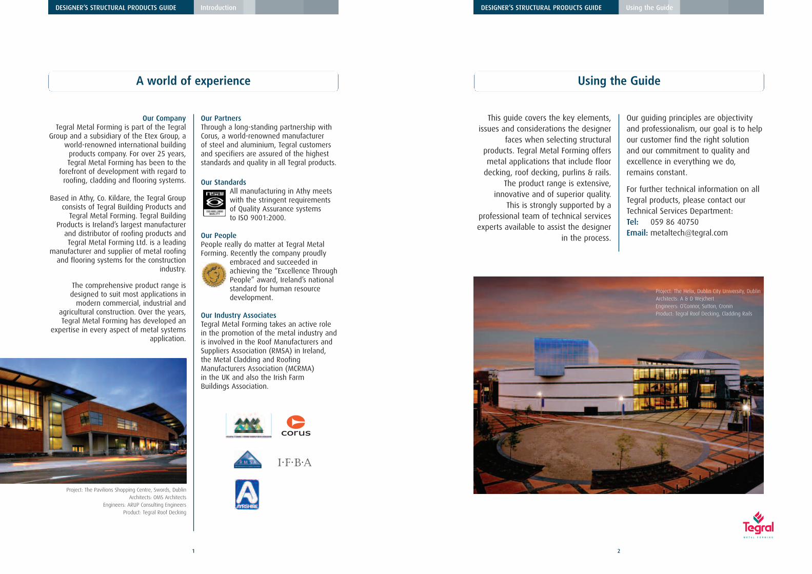
Project: The Helix, Dublin City University, DublinArchitects: A & D WejchertEngineers: O’Connor, Sutton, CroninProduct: Tegral Roof Decking, Cladding Rails
DESIGNER’S STRUCTURAL PRODUCTS GUIDE Product Range
Tegral Floor Decking
3
Product Range
Structural products from Tegral are designed andmanufactured to maximise the structural integrity
and effectiveness of metal in construction.
4
DESIGNER’S STRUCTURAL PRODUCTS GUIDE Product Range
Floor Decking, Roof Decking, Purlins & RailsThe Tegral range of structural products includes a largeselection of floor decking, roof decking and the Zetarange of purlins.
Tegframe Framing System
Light Gauge Steel Framing System combining thebenefits of cold-rolled steel framing with innovativedesign. Tegframe is the lightest, most steel-efficientframing system on the market.
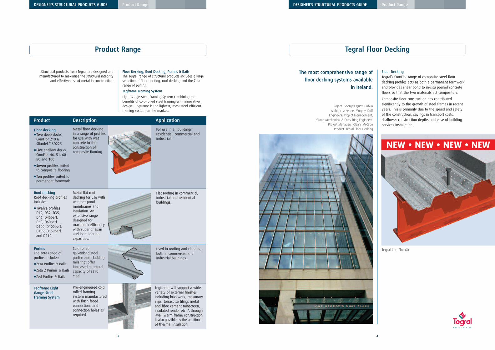
Floor DeckingTegral’s ComFlor range of composite steel floordecking profiles acts as both a permanent formworkand provides shear bond to in-situ poured concretefloors so that the two materials act compositely.
Composite floor construction has contributedsignificantly to the growth of steel frames in recentyears. This is primarily due to the speed and safetyof the construction, savings in transport costs,shallower construction depths and ease of buildingservices installation.
Tegral ComFlor 60
Product Description Application
Floor decking●Two deep decks
ComFlor 210 &Slimdek® SD225
●Five shallow decksComFlor 46, 51, 6080 and 100
●Seven profiles suited to composite flooring
●Ten profiles suited topermanent formwork
Metal floor deckingin a range of profilesfor use with wetconcrete in theconstruction ofcomposite flooring
For use in all buildingsresidential, commercial andindustrial.
Metal flat roofdecking for use withweather-proofmembranes andinsulation. Anextensive rangedesigned formaximum efficiencywith superior spanand load bearingcapacities.
Flat roofing in commercial,industrial and residentialbuildings.
PurlinsThe Zeta range ofpurlins includes:
●Zeta Purlins & Rails
●Zeta 2 Purlins & Rails
●Zed Purlins & Rails
Cold rolledgalvanised steelpurlins and claddingrails that offerincreased structuralcapacity of s390steel
Used in roofing and claddingboth in commercial andindustrial buildings.
Tegframe will support a widevariety of external finishesincluding brickwork, masonaryslips, terracotta tiling, metaland fibre cement rainscreen,insulated render etc. A through-wall warm frame constructionis also possible by the additionalof thermal insulation.
The use of cold-rolled galvanised steel purlins tocarry a chosen roofing assembly and cladding railsto support various cladding options, is widespread inall sectors of the construction industry.
Product RangeThe Tegral Zeta range of purlins offers increasedstructural capacity of S390 steel. This combined withthe choice of Tegral Zeta purlin and rail systemsavailable, provides the most efficient structuralarrangement possible. The range consists of Zeta,Zeta 2 and Zed purlins & rails.
DescriptionCold-rolled galvanised steel purlins and cladding thatrails support various roofing and claddingapplications.
ApplicationUsed in roofing and cladding in both commercial andindustrial buildings.
Tegral Zed purlins
Tegral Zeta purlins
233.3 63
120 105 225 67
40 112.5
152.5
Cover width 900
C
46
Cover width 610
Cover width 700
51
100
124.3
63
109
Cover width 800
Cover width 900
110200
64
67
90
233.3
60
46
100
210
Cover width 700
Cover width 600
425 87.7
1
10937
5256
22532.6
27.5
Cover width 600
Cover width 600
400 100
27.5
37.5
37.5 32.6
238
500
18090 120
15
100
ComFlor 46ComFlor 46ComFlor 46
F100F100F100
F60F60F60
F46F46F46
ComFlor 51ComFlor 51
ComFlor 60ComFlor 60
ComFlor 100ComFlor 100
ComFlor 210ComFlor 210
SD 225SD 225SD 225
ComFlor 80ComFlor 80ComFlor 80
ComFlor 210
ComFlor 100
ComFlor 51
80
300
105120225
Cover width 600
180 120
15
60
300
ComFlor 60
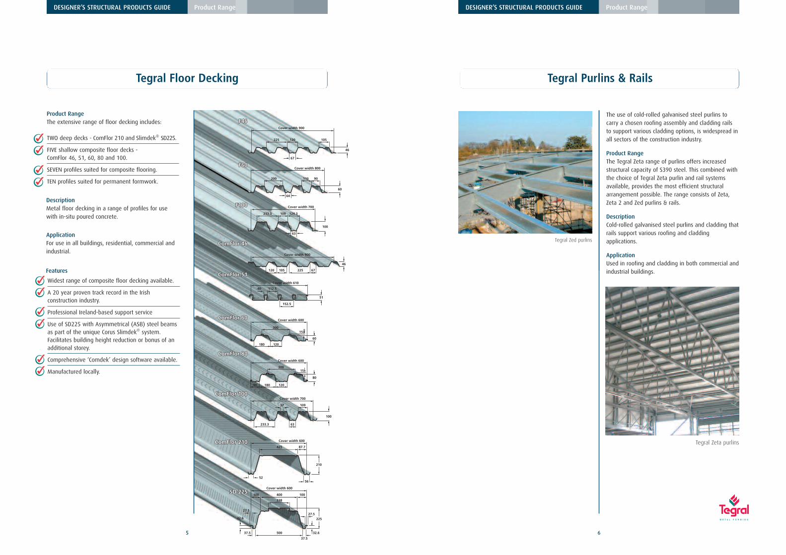
TWO deep decks - ComFlor 210 and Slimdek® SD225.
FIVE shallow composite floor decks - ComFlor 46, 51, 60, 80 and 100.
SEVEN profiles suited for composite flooring.
TEN profiles suited for permanent formwork.
Product RangeThe extensive range of floor decking includes:
Widest range of composite floor decking available.
A 20 year proven track record in the Irishconstruction industry.
Professional Ireland-based support service
Use of SD225 with Asymmetrical (ASB) steel beamsas part of the unique Corus Slimdek® system. Facilitates building height reduction or bonus of anadditional storey.
Comprehensive ‘Comdek’ design software available.
Manufactured locally.
Features
DescriptionMetal floor decking in a range of profiles for usewith in-situ poured concrete.
ApplicationFor use in all buildings, residential, commercial andindustrial.
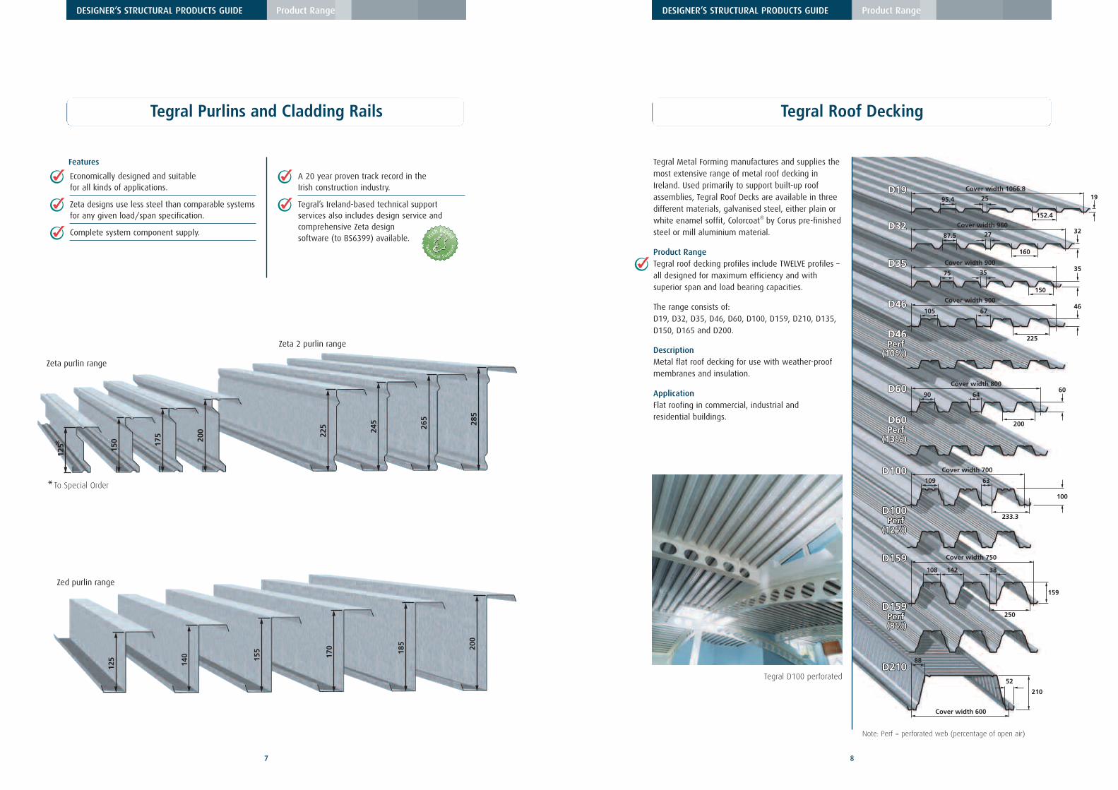
Tegral Metal Forming manufactures and supplies themost extensive range of metal roof decking inIreland. Used primarily to support built-up roofassemblies, Tegral Roof Decks are available in threedifferent materials, galvanised steel, either plain orwhite enamel soffit, Colorcoat® by Corus pre-finishedsteel or mill aluminium material.
Product RangeTegral roof decking profiles include TWELVE profiles –all designed for maximum efficiency and withsuperior span and load bearing capacities.
The range consists of: D19, D32, D35, D46, D60, D100, D159, D210, D135,D150, D165 and D200.
DescriptionMetal flat roof decking for use with weather-proofmembranes and insulation.
ApplicationFlat roofing in commercial, industrial and residential buildings.
Note: Perf = perforated web (percentage of open air)
Tegral Purlins and Cladding Rails
Economically designed and suitablefor all kinds of applications.
Zeta designs use less steel than comparable systemsfor any given load/span specification.
Complete system component supply.
A 20 year proven track record in theIrish construction industry.
Tegral’s Ireland-based technical supportservices also includes design service andcomprehensive Zeta designsoftware (to BS6399) available.
Features
125
140 15
5
170
185 200
125 15
0 175 200 22
5 245
265
285
Zeta purlin range
Zeta 2 purlin range
Zed purlin range
*
* To Special Order
Tegral D100 perforated
19
DESIGNER’S STRUCTURAL PRODUCTS GUIDE Product Range
310
136
Cover width 930
38173 137
280
153
Cover width 840
38172 108
250
159
Cover width 750
Cover width 750
142 10838
75
375
205
170 205
D135D135
D135 Perf
D135 D135PerfPerf
D135Perf
(19%)
D150D150
D150 D150Perf Perf
(21%)(21%)
D165 D165
D165Perf
(23%)
D200D200
D200 Perf
D200 D200PerfPerf
D200Perf
(22%)
D135
D150
D135 Perf
(19%)
D165
D200
D150 Perf
(21%)
D165 Perf
(23%)
D200 Perf
(22%)
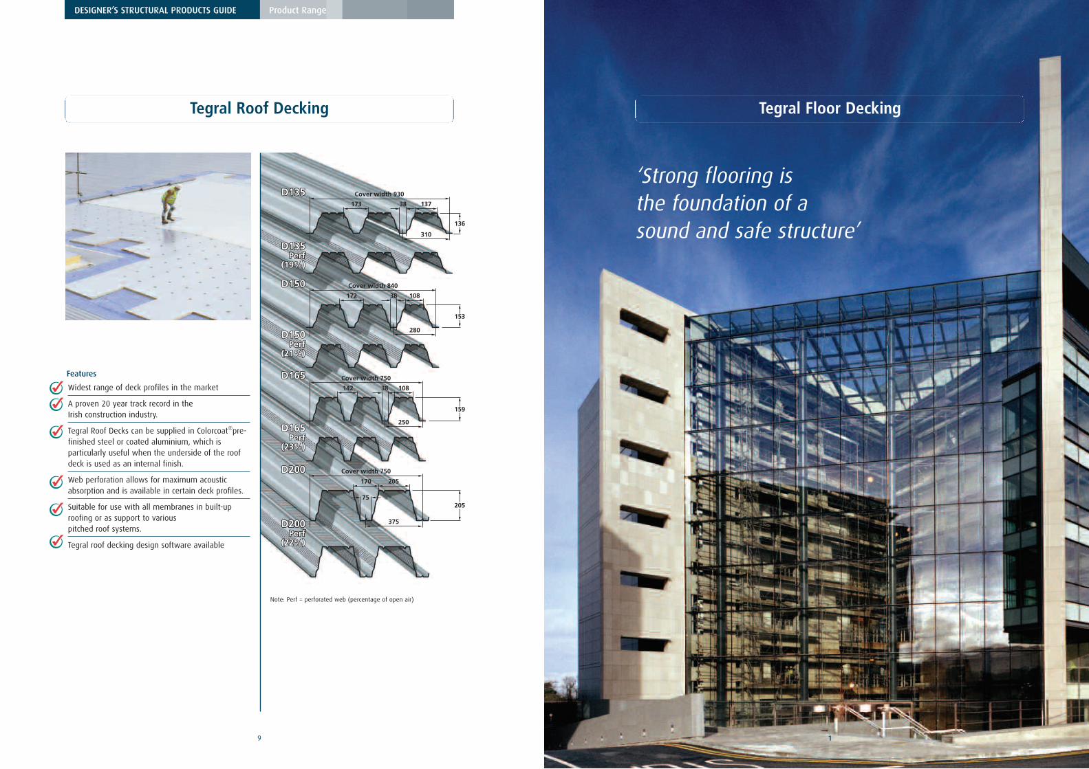
Note: Perf = perforated web (percentage of open air)
Widest range of deck profiles in the market
A proven 20 year track record in theIrish construction industry.
Tegral Roof Decks can be supplied in Colorcoat®pre-finished steel or coated aluminium, which isparticularly useful when the underside of the roofdeck is used as an internal finish.
Web perforation allows for maximum acousticabsorption and is available in certain deck profiles.
Suitable for use with all membranes in built-uproofing or as support to variouspitched roof systems.
Tegral roof decking design software available
Features
Tegral Roof Decking Tegral Floor Decking
‘Strong flooring is the foundation of a sound and safe structure’
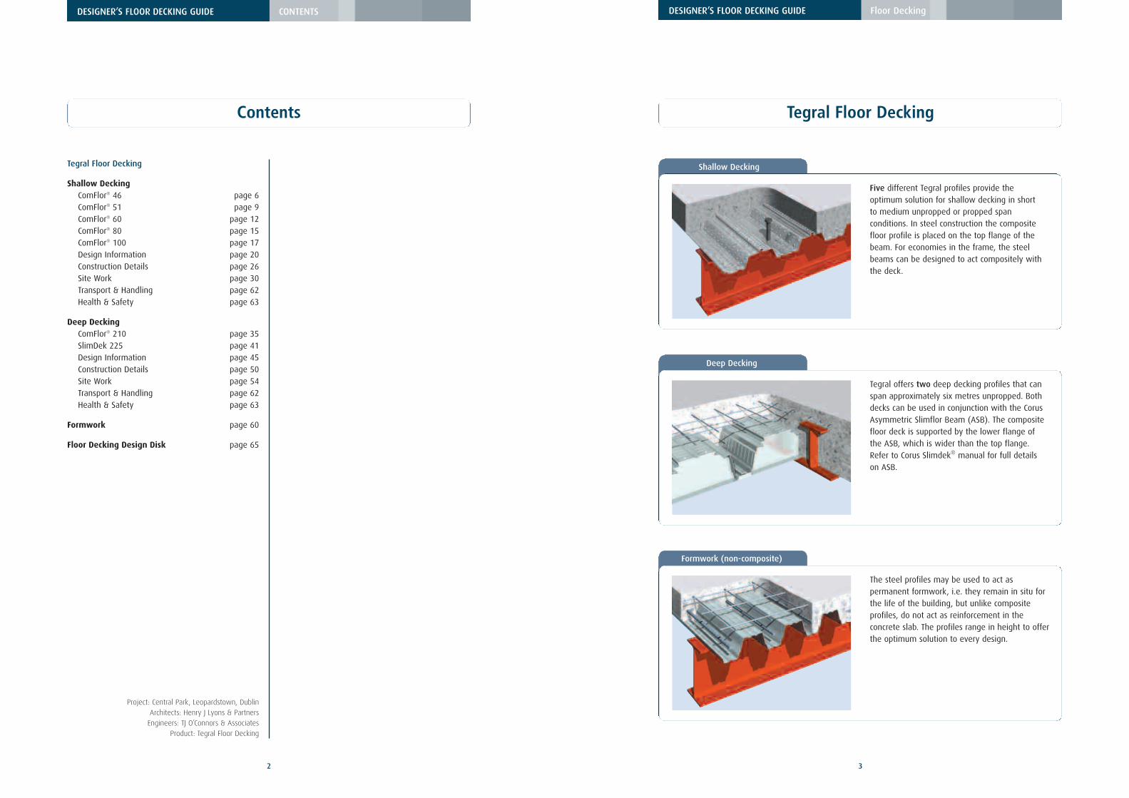
Five different Tegral profiles provide theoptimum solution for shallow decking in shortto medium unpropped or propped spanconditions. In steel construction the compositefloor profile is placed on the top flange of thebeam. For economies in the frame, the steelbeams can be designed to act compositely withthe deck.
Deep Decking
Tegral offers two deep decking profiles that canspan approximately six metres unpropped. Bothdecks can be used in conjunction with the CorusAsymmetric Slimflor Beam (ASB). The compositefloor deck is supported by the lower flange ofthe ASB, which is wider than the top flange.Refer to Corus Slimdek® manual for full detailson ASB.
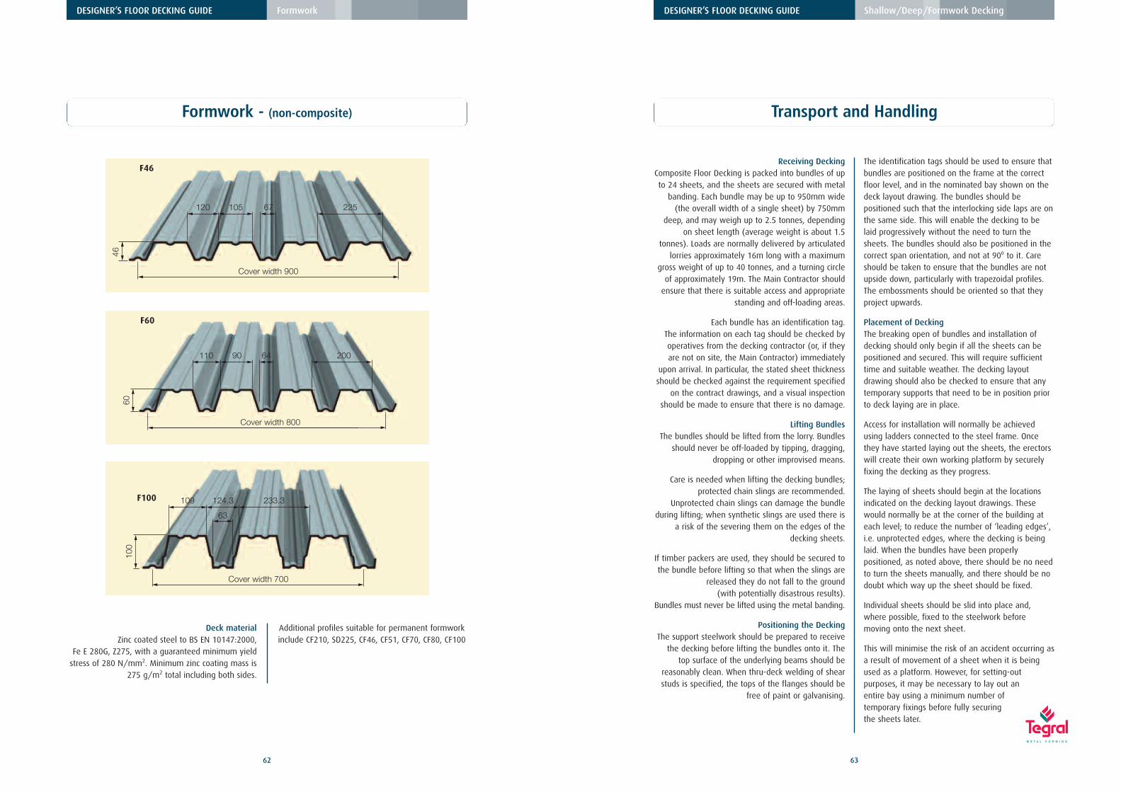
Formwork (non-composite)
The steel profiles may be used to act aspermanent formwork, i.e. they remain in situ forthe life of the building, but unlike compositeprofiles, do not act as reinforcement in theconcrete slab. The profiles range in height to offerthe optimum solution to every design.
Tegral Shallow Decking
Project: Burgh Quay, DublinArchitects: Henry J Lyons & PartnersEngineers: Structural Engineers, Lee McCulloch & PartnersProduct: Tegral Floor Decking
54
SpeedLarge areas of deck can be rapidly craned intoposition and up to 400m2 laid by one team per day.With minimal mesh reinforcement and pumpedconcrete, the completed floor can quickly follow.
Working platformOnce fixed, the deck acts as a safe working platformfor all following trades. Temporary props can usuallybe eliminated.
Construction stage bracingThe deck acts as lateral restraint to the beams andserves as a diaphragm, transmitting wind load fromthe outer steelwork to the core. Thus once thedecking is fixed, it contributes significantly to thestability of the structure.
WeightDue to the intrinsic efficiency of compositeconstruction and the displacement of concrete by theprofile shape, considerably less concrete is used thanin conventional reinforced concrete construction.This reduces the weight of both the primary structureand foundations.
Floor heightComposite beams use the slab as a compressionelement, which increases their stiffness and reducestheir size. The composite slab itself has a very lowcentre of reinforcement compared to a conventionallyreinforced slab and therefore does not need thesame depth. These savings mean reduced floor zoneand thus contribute to the overall floor height.
FireExtensive testing and fire engineering work by CorusPanels & Profiles and The Steel Construction Institutehave resulted in fire ratings of up to 4 hours beingavailable with the use of light mesh fibre within thecomposite slab and no protection to the deck profile.
ServicesTegral composite floor decking incorporate systemsfor the easy attachment of services, negating therequirement to fix into concrete.
Product benefits
DESIGNER’S FLOOR DECKING GUIDE Floor Decking
Tegral Floor Decking
Fibre concreteTegral shallow composite floor decking has beentested for use with fibre-reinforced concrete,avoiding the need for delivery, lifting and installationof welded wire mesh on the floor prior to pouringconcrete. Significantly this can reduce installationtimes by up to 20%.
Multi-storey Car ParksTegral CF60 and CF80 composite floor decking maybe used for car decks. Please contact TechnicalServices for further information.
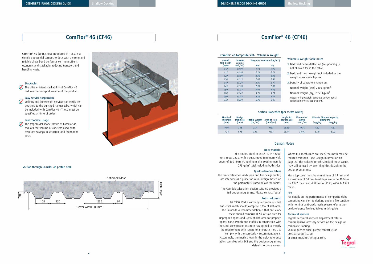
105
46
Slab
Dep
th
120 225 67
3
Cover width 900mm
C
Anticrack Mesh
StackableThe ultra efficient stackability of ComFlor 46reduces the transport volume of the product.
Easy service suspensionCeilings and lightweight services can easily beattached to the punched hangar tabs, which canbe included with ComFlor 46. (These must bespecified at time of order.)
Low concrete usageThe trapezoidal shape profile of ComFlor 46reduces the volume of concrete used, withresultant savings in structural and foundationcosts.
ComFlor® 46 (CF46)
ComFlor® 46 (CF46), first introduced in 1985, is asimple trapezoidal composite deck with a strong andreliable shear bond performance. The profile iseconomic and stackable, reducing transport andhandling costs.
6
DESIGNER’S FLOOR DECKING GUIDE Shallow Decking
Section through ComFlor 46 profile deck
ComFlor® 46 Composite Slab - Volume & Weight
Overall Concrete Weight of Concrete (kN/m2 )Slab Depth volume
(mm) (m3/m2) Wet Dry
110 0.091 2.14 2.10
115 0.096 2.26 2.21
120 0.101 2.38 2.33
130 0.111 2.61 2.56
140 0.121 2.85 2.79
145 0.126 2.96 2.90
150 0.131 3.08 3.02
180 0.161 3.79 3.71
200 0.181 4.26 4.17
240 0.221 5.20 5.09
7
DESIGNER’S FLOOR DECKING GUIDE Shallow Decking
Design Notes
ComFlor® 46 (CF46)
Deck materialZinc coated steel to BS EN 10147:2000,
Fe E 280G, Z275, with a guaranteed minimum yieldstress of 280 N/mm2. Minimum zinc coating mass is
275 g/m2 total including both sides.
Quick reference tablesThe quick reference load/span and fire design tables,
are intended as a guide for initial design, based onthe parameters stated below the tables.
The Comdek calculation design suite CD provides afull design programme. Please contact Tegral.
Anti-crack meshBS 5950: Part 4 currently recommends that
anti-crack mesh should comprise 0.1% of slab area.The Eurocode 4 recommendation is that anti-crack
mesh should comprise 0.2% of slab area forunpropped spans and 0.4% of slab area for proppedspans. Corus Panels and Profiles in conjunction with
The Steel Construction Institute has agreed to modifythe requirement with regard to anti-crack mesh, to
comply with the Eurocode 4 recommendations.Accordingly, the mesh shown in the quick reference
tables complies with EC4 and the design programmedefaults to these values.
Volume & weight table notes
1.Deck and beam deflection (i.e. ponding isnot allowed for in the table.
2.Deck and mesh weight not included in theweight of concrete figures.
3.Density of concrete is taken as:
Normal weight (wet) 2400 kg/m2
Normal weight (dry) 2350 kg/m2
Note: For lightweight concrete contact TegralTechnical Services Department.
Section Properties (per metre width)
Nominal Design Height to Moment of Ultimate Moment capacitythickness thickness Profile weight Area of steel neutral axis inertia (kNm/m)
Where EC4 mesh rules are used, the mesh may bereduced midspan - see Design Information on page 20. The reduced British Standard mesh valuesmay still be used by overriding this default in thedesign programme.
Mesh top cover must be a minimum of 15mm, anda maximum of 30mm. Mesh laps are to be 300mmfor A142 mesh and 400mm for A193, A252 & A393mesh.
FireFor details on the performance of composite slabscomprising ComFlor 46 decking under a fire conditionwith nominal anti-crack mesh, please refer to thequick reference fire load tables in this guide.
Technical servicesTegral’s Technical Services Department offer acomprehensive advisory service on the design ofcomposite flooring. Should queries arise, please contact us on 00+353 59 86 40750 or email [email protected].
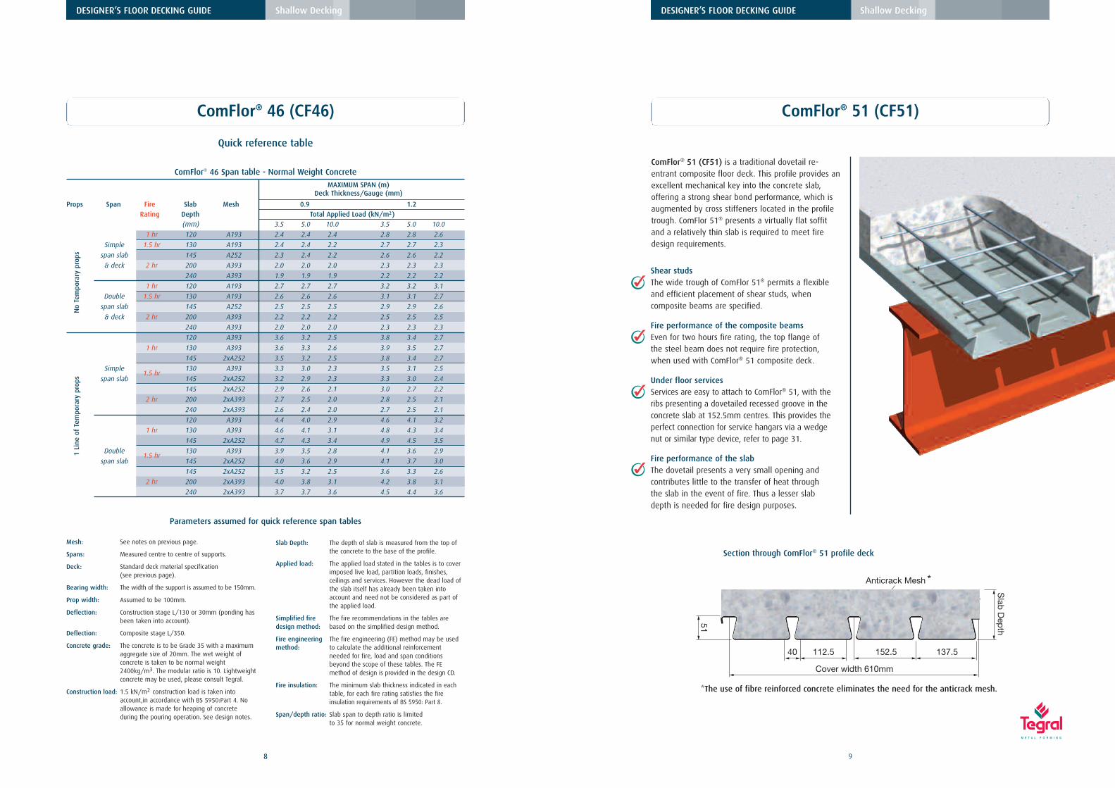
ComFlor® 46 Span table - Normal Weight Concrete
MAXIMUM SPAN (m)Deck Thickness/Gauge (mm)
Props Span Fire Slab Mesh 0.9 1.2Rating Depth Total Applied Load (kN/m2)
(mm) 3.5 5.0 10.0 3.5 5.0 10.0
1 hr 120 A193 2.4 2.4 2.4 2.8 2.8 2.6
Simple 1.5 hr 130 A193 2.4 2.4 2.2 2.7 2.7 2.3
span slab 145 A252 2.3 2.4 2.2 2.6 2.6 2.2
& deck 2 hr 200 A393 2.0 2.0 2.0 2.3 2.3 2.3
240 A393 1.9 1.9 1.9 2.2 2.2 2.2
1 hr 120 A193 2.7 2.7 2.7 3.2 3.2 3.1
Double 1.5 hr 130 A193 2.6 2.6 2.6 3.1 3.1 2.7
span slab 145 A252 2.5 2.5 2.5 2.9 2.9 2.6
& deck 2 hr 200 A393 2.2 2.2 2.2 2.5 2.5 2.5
240 A393 2.0 2.0 2.0 2.3 2.3 2.3
120 A393 3.6 3.2 2.5 3.8 3.4 2.7
1 hr 130 A393 3.6 3.3 2.6 3.9 3.5 2.7
145 2xA252 3.5 3.2 2.5 3.8 3.4 2.7
Simple1.5 hr
130 A393 3.3 3.0 2.3 3.5 3.1 2.5
span slab 145 2xA252 3.2 2.9 2.3 3.3 3.0 2.4
145 2xA252 2.9 2.6 2.1 3.0 2.7 2.2
2 hr 200 2xA393 2.7 2.5 2.0 2.8 2.5 2.1
240 2xA393 2.6 2.4 2.0 2.7 2.5 2.1
120 A393 4.4 4.0 2.9 4.6 4.1 3.2
1 hr 130 A393 4.6 4.1 3.1 4.8 4.3 3.4
145 2xA252 4.7 4.3 3.4 4.9 4.5 3.5
Double1.5 hr
130 A393 3.9 3.5 2.8 4.1 3.6 2.9
span slab 145 2xA252 4.0 3.6 2.9 4.1 3.7 3.0
145 2xA252 3.5 3.2 2.5 3.6 3.3 2.6
2 hr 200 2xA393 4.0 3.8 3.1 4.2 3.8 3.1
240 2xA393 3.7 3.7 3.6 4.5 4.4 3.6
8
DESIGNER’S FLOOR DECKING GUIDE Shallow Decking
Quick reference table
ComFlor® 46 (CF46)
Mesh: See notes on previous page.
Spans: Measured centre to centre of supports.
Deck: Standard deck material specification (see previous page).
Bearing width: The width of the support is assumed to be 150mm.
Prop width: Assumed to be 100mm.
Deflection: Construction stage L/130 or 30mm (ponding hasbeen taken into account).
Deflection: Composite stage L/350.
Concrete grade: The concrete is to be Grade 35 with a maximum aggregate size of 20mm. The wet weight of concrete is taken to be normal weight 2400kg/m3. The modular ratio is 10. Lightweightconcrete may be used, please consult Tegral.
Construction load: 1.5 kN/m2 construction load is taken into account,in accordance with BS 5950:Part 4. No allowance is made for heaping of concrete during the pouring operation. See design notes.
Slab Depth: The depth of slab is measured from the top of the concrete to the base of the profile.
Applied load: The applied load stated in the tables is to cover imposed live load, partition loads, finishes, ceilings and services. However the dead load of the slab itself has already been taken into account and need not be considered as part of the applied load.
Simplified fire The fire recommendations in the tables aredesign method: based on the simplified design method.
Fire engineering The fire engineering (FE) method may be usedmethod: to calculate the additional reinforcement
needed for fire, load and span conditions beyond the scope of these tables. The FE method of design is provided in the design CD.
Fire insulation: The minimum slab thickness indicated in each table, for each fire rating satisfies the fire insulation requirements of BS 5950: Part 8.
Span/depth ratio: Slab span to depth ratio is limited to 35 for normal weight concrete.
No
Tem
pora
rypr
ops
1Li
neof
Tem
pora
rypr
ops
Parameters assumed for quick reference span tables
Shear studsThe wide trough of ComFlor 51® permits a flexibleand efficient placement of shear studs, whencomposite beams are specified.
Fire performance of the composite beamsEven for two hours fire rating, the top flange ofthe steel beam does not require fire protection,when used with ComFlor® 51 composite deck.
Under floor servicesServices are easy to attach to ComFlor® 51, with theribs presenting a dovetailed recessed groove in theconcrete slab at 152.5mm centres. This provides theperfect connection for service hangars via a wedgenut or similar type device, refer to page 31.
Fire performance of the slabThe dovetail presents a very small opening andcontributes little to the transfer of heat throughthe slab in the event of fire. Thus a lesser slabdepth is needed for fire design purposes.
Slab
Dep
th
51
Cover width 610mm
152.5 137.5112.540
Anticrack Mesh
ComFlor® 51 (CF51)
ComFlor® 51 (CF51) is a traditional dovetail re-entrant composite floor deck. This profile provides anexcellent mechanical key into the concrete slab,offering a strong shear bond performance, which isaugmented by cross stiffeners located in the profiletrough. ComFlor 51® presents a virtually flat soffitand a relatively thin slab is required to meet firedesign requirements.
9
DESIGNER’S FLOOR DECKING GUIDE Shallow Decking
Section through ComFlor® 51 profile deck
*The use of fibre reinforced concrete eliminates the need for the anticrack mesh.
*
10
DESIGNER’S FLOOR DECKING GUIDE Shallow Decking
ComFlor® 51 (CF51)
Design Notes
Deck materialZinc coated steel to BS EN 10147:2000,
Fe E 350G, Z275, with a guaranteed minimum yieldstress of 350 N/mm2. Minimum zinc coating mass is
275 g/m2 total including both sides.
Quick reference tablesThe quick reference load/span and fire design tables,
are intended as a guide for initial design, based onthe parameters stated below the tables.
The Comdek calculation design suite CD provides afull design programme. Please contact Tegral.
Anti-crack meshBS 5950: Part 4 currently recommends that anti-crack
mesh should comprise 0.1% of slab area. TheEurocode 4 recommendation is that anti-crack mesh
should comprise 0.2% of slab area for unproppedspans and 0.4% of slab area for propped spans.
Corus Panels and Profiles in conjunction with TheSteel Construction Institute has agreed to modify the
requirement with regard to anti-crack mesh, tocomply with the Eurocode 4 recommendations.
Accordingly, the mesh shown in the quick referencetables complies with EC4 and the design programme
defaults to these values.
Volume & weight table notes
1.Deck and beam deflection (i.e. ponding isnot allowed for in the table.
2.Deck and mesh weight not included in theweight of concrete figures.
3.Density of concrete is taken as:
Normal weight (wet) 2400 kg/m2
Normal weight (dry) 2350 kg/m2
Note: For lightweight concrete contact TegralTechnical Services Department.
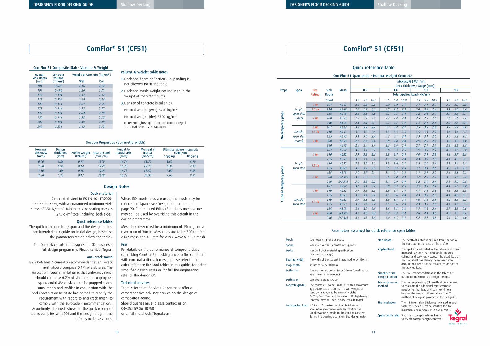
Section Properties (per metre width)
Nominal Design Height to Moment of Ultimate Moment capacitythickness thickness Profile weight Area of steel neutral axis inertia (kNm/m)
Where EC4 mesh rules are used, the mesh may bereduced midspan - see Design Information on page 20. The reduced British Standards mesh valuesmay still be used by overriding this default in thedesign programme.
Mesh top cover must be a minimum of 15mm, and amaximum of 30mm. Mesh laps are to be 300mm forA142 mesh and 400mm for A193, A252 & A393 mesh.
FireFor details on the performance of composite slabscomprising ComFlor 51 decking under a fire conditionwith nominal anti-crack mesh, please refer to thequick reference fire load tables in this guide. For othersimplified design cases or for full fire engineering,refer to the design CD.
Technical servicesTegral’s Technical Services Department offer acomprehensive advisory service on the design ofcomposite flooring. Should queries arise, please contact us on 00+353 59 86 40750 or email [email protected].
ComFlor 51 Composite Slab - Volume & Weight
Overall Concrete Weight of Concrete (kN/m2 )Slab Depth volume
(mm) (m3/m2) Wet Dry
101 0.092 2.16 2.12
105 0.096 2.26 2.21
110 0.101 2.37 2.32
115 0.106 2.49 2.44
120 0.111 2.61 2.55
125 0.116 2.73 2.67
130 0.121 2.84 2.78
150 0.141 3.32 3.25
200 0.191 4.49 4.40
240 0.231 5.43 5.32
No
Tem
pora
rypr
ops
1Li
ne
ofTe
mpo
rary
prop
s
11
DESIGNER’S FLOOR DECKING GUIDE Shallow Decking
Quick reference table
ComFlor® 51 (CF51)
Mesh: See notes on previous page.
Spans: Measured centre to centre of supports.
Deck: Standard deck material specification (see previous page).
Bearing width: The width of the support is assumed to be 150mm.
Prop width: Assumed to be 100mm.
Deflection: Construction stage L/130 or 30mm (ponding hasbeen taken into account).
Deflection: Composite stage L/350.
Concrete grade: The concrete is to be Grade 35 with a maximum aggregate size of 20mm. The wet weight of concrete is taken to be normal weight 2400kg/m3. The modular ratio is 10. Lightweightconcrete may be used, please consult Tegral.
Construction load: 1.5 kN/m2 construction load is taken into account,in accordance with BS 5950:Part 4. No allowance is made for heaping of concrete during the pouring operation. See design notes.
Slab Depth: The depth of slab is measured from the top of the concrete to the base of the profile.
Applied load: The applied load stated in the tables is to cover imposed live load, partition loads, finishes, ceilings and services. However the dead load of the slab itself has already been taken into account and need not be considered as part of the applied load.
Simplified fire The fire recommendations in the tables aredesign method: based on the simplified design method.
Fire engineering The fire engineering (FE) method may be usedmethod: to calculate the additional reinforcement
needed for fire, load and span conditions beyond the scope of these tables. The FE method of design is provided in the design CD.
Fire insulation: The minimum slab thickness indicated in each table, for each fire rating satisfies the fireinsulation requirements of BS 5950: Part 8.
Span/depth ratio: Slab span to depth ratio is limited to 35 for normal weight concrete.
Parameters assumed for quick reference span tables
ComFlor 51 Span table - Normal weight Concrete
MAXIMUM SPAN (m)Deck Thickness/Gauge (mm)
Props Span Fire Slab Mesh 0.9 1.0 1.1 1.2Rating Depth Total Applied Load (kN/m2)
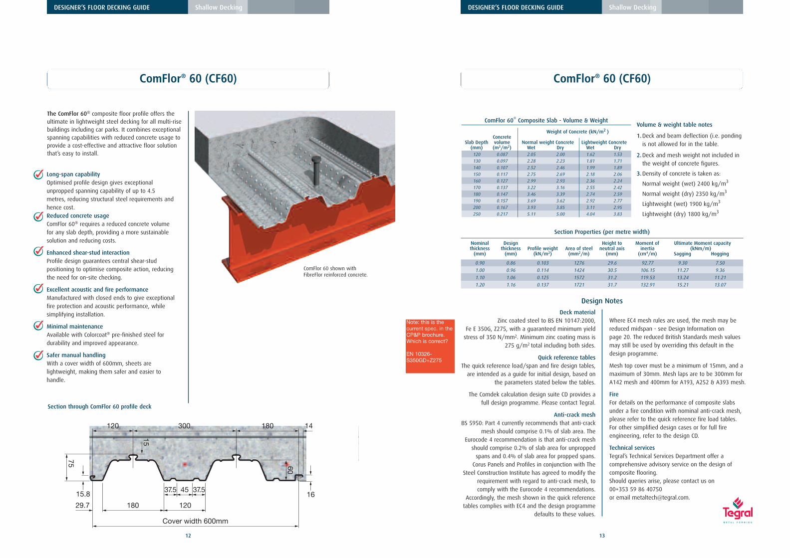
The ComFlor 60® composite floor profile offers theultimate in lightweight steel decking for all multi-risebuildings including car parks. It combines exceptionalspanning capabilities with reduced concrete usage toprovide a cost-effective and attractive floor solutionthat’s easy to install.
DESIGNER’S FLOOR DECKING GUIDE Shallow Decking
Long-span capability Optimised profile design gives exceptionalunpropped spanning capability of up to 4.5metres, reducing structural steel requirements andhence cost.Reduced concrete usageComFlor 60® requires a reduced concrete volumefor any slab depth, providing a more sustainablesolution and reducing costs.
Enhanced shear-stud interactionProfile design guarantees central shear-studpositioning to optimise composite action, reducingthe need for on-site checking.
Excellent acoustic and fire performanceManufactured with closed ends to give exceptionalfire protection and acoustic performance, whilesimplifying installation.
Minimal maintenanceAvailable with Colorcoat® pre-finished steel fordurability and improved appearance.
Safer manual handlingWith a cover width of 600mm, sheets arelightweight, making them safer and easier tohandle.
Section through ComFlor 60 profile deck
DESIGNER’S FLOOR DECKING GUIDE Shallow Decking
Volume & weight table notes
1.Deck and beam deflection (i.e. ponding is not allowed for in the table.
2.Deck and mesh weight not included in the weight of concrete figures.
3.Density of concrete is taken as:
Normal weight (wet) 2400 kg/m3
Normal weight (dry) 2350 kg/m3
Lightweight (wet) 1900 kg/m3
Lightweight (dry) 1800 kg/m3
Section Properties (per metre width)
Nominal Design Height to Moment of Ultimate Moment capacitythickness thickness Profile weight Area of steel neutral axis inertia (kNm/m)
Deck materialZinc coated steel to BS EN 10147:2000,
Fe E 350G, Z275, with a guaranteed minimum yieldstress of 350 N/mm2. Minimum zinc coating mass is
275 g/m2 total including both sides.
Quick reference tablesThe quick reference load/span and fire design tables,
are intended as a guide for initial design, based onthe parameters stated below the tables.
The Comdek calculation design suite CD provides afull design programme. Please contact Tegral.
Anti-crack meshBS 5950: Part 4 currently recommends that anti-crack
mesh should comprise 0.1% of slab area. TheEurocode 4 recommendation is that anti-crack mesh
should comprise 0.2% of slab area for unproppedspans and 0.4% of slab area for propped spans.
Corus Panels and Profiles in conjunction with TheSteel Construction Institute has agreed to modify the
requirement with regard to anti-crack mesh, tocomply with the Eurocode 4 recommendations.
Accordingly, the mesh shown in the quick referencetables complies with EC4 and the design programme
defaults to these values.
Where EC4 mesh rules are used, the mesh may bereduced midspan - see Design Information on page 20. The reduced British Standards mesh valuesmay still be used by overriding this default in thedesign programme.
Mesh top cover must be a minimum of 15mm, and amaximum of 30mm. Mesh laps are to be 300mm forA142 mesh and 400mm for A193, A252 & A393 mesh.
FireFor details on the performance of composite slabsunder a fire condition with nominal anti-crack mesh,please refer to the quick reference fire load tables. For other simplified design cases or for full fireengineering, refer to the design CD.
Technical servicesTegral’s Technical Services Department offer acomprehensive advisory service on the design ofcomposite flooring. Should queries arise, please contact us on 00+353 59 86 40750 or email [email protected].
Mesh: See notes on previous page. (Mesh is not required for FibreFlor)
Spans: Measured centre to centre of supports.
Deck: Standard deck material specification (see previous page).
Bearing width: The width of the support is assumed to be 150mm.
Prop width: Assumed to be 100mm.
Deflection: Construction stage L/130 or 30mm (ponding hasbeen taken into account).
Deflection: Composite stage L/350.
Concrete grade: The concrete is to be Grade 35 with a maximum aggregate size of 20mm. The wet weight of concrete is taken to be normal weight 2400kg/m3. The modular ratio is 10. Lightweightconcrete may be used, please consult Tegral.
Construction load: 1.5 kN/m2 construction load is taken into account,in accordance with BS 5950:Part 4. No allowance is made for heaping of concrete during the pouring operation. See design notes.
Slab Depth: The depth of slab is measured from the top of the concrete to the base of the profile.
Applied load: The applied load stated in the tables is to cover imposed live load, partition loads, finishes, ceilings and services. However the dead load of the slab itself has already been taken into account and need not be considered as part of the applied load.
Simplified fire The fire recommendations in the tables aredesign method: based on the simplified design method.
Fire engineering The fire engineering (FE) method may be usedmethod: to calculate the additional reinforcement
needed for fire, load and span conditions beyond the scope of these tables. The FE method of design is provided in the design CD.
Fire insulation: The minimum slab thickness indicated in each table, for each fire rating satisfies the fire insulation requirements of BS 5950: Part 8.
Span/depth ratio: Slab span to depth ratio is limited to 35 for normal weight concrete.
Parameters assumed for quick reference span tables
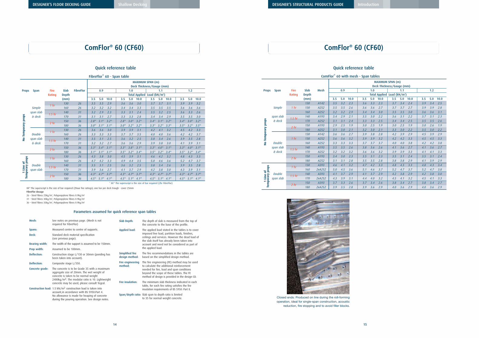
FibreFlor® 60 - Span table
MAXIMUM SPAN (m)Deck Thickness/Gauge (mm)
Props Span Fire Slab FibreFlor 0.9 1.0 1.1 1.2Rating Depth Total Applied Load (kN/m2)
Quick Reference Tables: All spans are shown in metres and are based on
supported unpropped conditions.
The load/span table above shows typical spanning condition for the ComFlor 80 profile.For variations of slab depth, loading conditions (including point loads), support conditions and the use of lightweight concrete we recommend the use of the Comdek software, available fromTegral.
Spans: Spans are measured centre to centre of support, support width is 150mm in tables.
Construction Load: of 1.5kN/m2 is taken into account in accordance with BS5950: Part 4 no allowance has been made for heaping of concrete during the casting of the slab.
Deflection: Construction stage L/130 or 30mm (ponding has been taken into account).
Fire Insulation: the minimum slab thickness indicated in each table satisfies the fire insulation requirements of BS5950: Part 8.
Parameters assumed for quick reference span tables
Section Properties (per metre width)
Nominal Design Profile Area of Height to Moment Ultimate Moment capacityThickness thickness Weight steel neutral axis of inertia (kN/m)
1.Deck and beam deflection (i.e. ponding) is notallowed for in the table.
2.Density of concrete is taken as:
Normal weight (wet) 2400 kg/m2
Normal weight (dry) 2350 kg/m2
Note: For lightweight concrete, contact Tegral TechnicalServices Department.
DESIGNER’S FLOOR DECKING GUIDE Shallow Decking
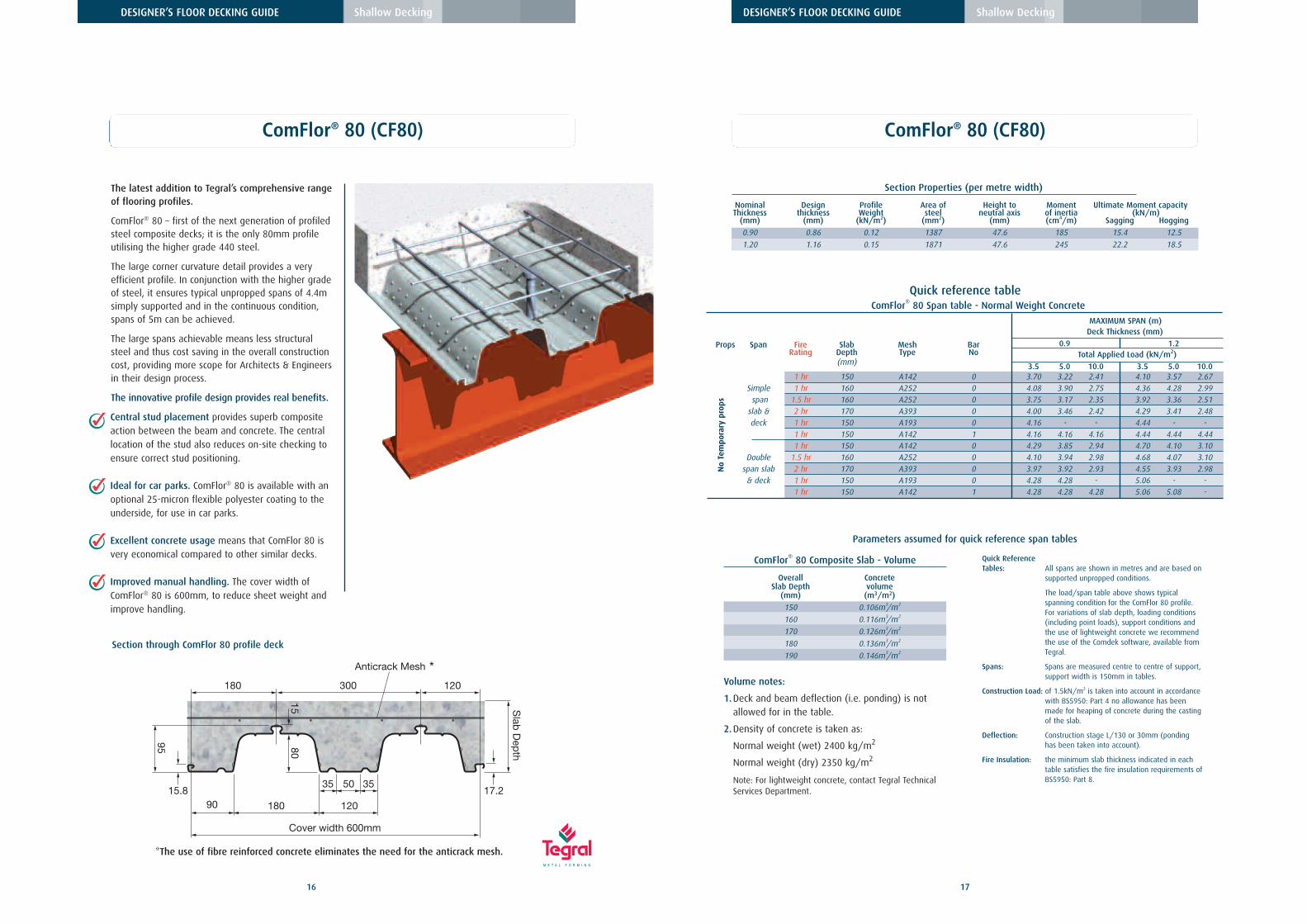
ComFlor® 80 (CF80)
Anticrack Mesh
Slab
Dep
th
90 120180
Cover width 600mm
S
95
50 3517.2
35
180 300 120
8015
15.8
Central stud placement provides superb compositeaction between the beam and concrete. The centrallocation of the stud also reduces on-site checking toensure correct stud positioning.
Ideal for car parks. ComFlor® 80 is available with anoptional 25-micron flexible polyester coating to theunderside, for use in car parks.
Excellent concrete usage means that ComFlor 80 isvery economical compared to other similar decks.
Improved manual handling. The cover width ofComFlor® 80 is 600mm, to reduce sheet weight andimprove handling.
Section through ComFlor 80 profile deck
*The use of fibre reinforced concrete eliminates the need for the anticrack mesh.
*
The latest addition to Tegral’s comprehensive rangeof flooring profiles.
ComFlor® 80 – first of the next generation of profiledsteel composite decks; it is the only 80mm profileutilising the higher grade 440 steel.
The large corner curvature detail provides a veryefficient profile. In conjunction with the higher gradeof steel, it ensures typical unpropped spans of 4.4msimply supported and in the continuous condition,spans of 5m can be achieved.
The large spans achievable means less structuralsteel and thus cost saving in the overall constructioncost, providing more scope for Architects & Engineersin their design process.
The innovative profile design provides real benefits.
18
DESIGNER’S STRUCTURAL PRODUCTS GUIDE Introduction
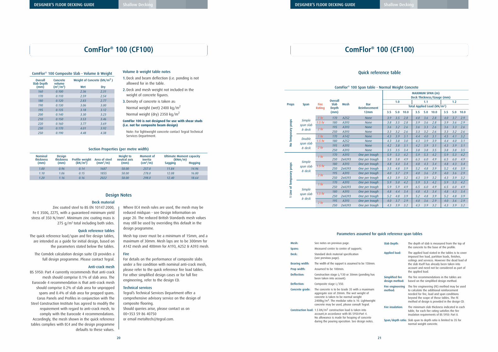
No temporary propsComFlor® 100 can carry wet concrete andconstruction loads to 4.5m without temporarypropping, (depending on slab depth) therebyleaving a clear area beneath the floor underconstruction. Further savings of labour and prop hireare also realised.
Large concrete volume reductionAlthough a deep slab is required, the ComFlor® 100profile greatly reduces the volume of concreteneeded and thus the cost and weight of concrete.
Suitable for traditional constructionComFlor® 100 is suitable to be placed ontomasonry walls or standard design non-compositesteel beams. As shear studding is not possible withComFlor 100 Composite beam design may not beconsidered.
ComFlor® 100 (CF100)
ComFlor® 100 (CF100), has a very strong profileshape and offers the capability to span up to4.5metres without props. Designed particularly forlonger unpropped spans. However, the profile is notsuitable for use with shear stud connectors.
233.3 37 63 109
8
Slab
Dep
th
100
Cover width 700mm
C
Anticrack Mesh
19
DESIGNER’S FLOOR DECKING GUIDE Shallow Decking
Section through ComFlor 100 profile deck
FibreFlor CF80 - Span table - Normal Weight Concrete
MAXIMUM SPAN (m) MAXIMUM SPAN (m)with no extra reinforcements with a bar in the trough**
Deck Thickness (mm) Deck Thickness (mm)
Props Span Fire Slab FibreFlor 0.9 1.2 0.9 1.2Rating Depth Total Applied Load (kN/m2)
Deck materialZinc coated steel to BS EN 10147:2000,
Fe E 350G, Z275, with a guaranteed minimum yieldstress of 350 N/mm2. Minimum zinc coating mass is
275 g/m2 total including both sides.
Quick reference tablesThe quick reference load/span and fire design tables,
are intended as a guide for initial design, based onthe parameters stated below the tables.
The Comdek calculation design suite CD provides afull design programme. Please contact Tegral.
Anti-crack meshBS 5950: Part 4 currently recommends that anti-crack
mesh should comprise 0.1% of slab area. TheEurocode 4 recommendation is that anti-crack mesh
should comprise 0.2% of slab area for unproppedspans and 0.4% of slab area for propped spans.
Corus Panels and Profiles in conjunction with TheSteel Construction Institute has agreed to modify the
requirement with regard to anti-crack mesh, tocomply with the Eurocode 4 recommendations.
Accordingly, the mesh shown in the quick referencetables complies with EC4 and the design programme
defaults to these values.
Where EC4 mesh rules are used, the mesh may bereduced midspan - see Design Information on page 20. The reduced British Standards mesh valuesmay still be used by overriding this default in thedesign programme.
Mesh top cover must be a minimum of 15mm, and amaximum of 30mm. Mesh laps are to be 300mm forA142 mesh and 400mm for A193, A252 & A393 mesh.
FireFor details on the performance of composite slabsunder a fire condition with nominal anti-crack mesh,please refer to the quick reference fire load tables. For other simplified design cases or for full fireengineering, refer to the design CD.
Technical servicesTegral’s Technical Services Department offer acomprehensive advisory service on the design ofcomposite flooring. Should queries arise, please contact us on 00+353 59 86 40750 or email [email protected].
ComFlor® 100 Span table - Normal Weight Concrete
MAXIMUM SPAN (m)
OverallDeck Thickness/Gauge (mm)
Props Span Fire Slab Mesh Bar1.0 1.1 1.2
Rating Depth Reinforcement Total Applied Load (kN/m2)
1 hr170 A393 One per trough 5.9 5.3 4.2 5.9 5.3 4.2 5.9 5.3 4.2
250 2xA393 One per trough 5.8 5.8 4.9 6.3 6.0 4.9 6.5 6.0 4.9Simple
1.5 hr180 A393 One per trough 4.8 4.4 3.4 4.8 4.3 3.4 4.8 4.3 3.4
span slab250 2xA393 One per trough 3.5 4.8 3.9 5.2 4.8 3.9 5.2 4.8 3.9
& deck2 hr
195 A393 One per trough 4.0 3.7 2.9 4.0 3.6 2.9 4.0 3.6 2.9
250 2xA393 One per trough 4.3 3.9 3.2 4.3 3.9 3.2 4.3 3.9 3.2
1 hr170 A393 One per trough 5.9 5.0 4.2 5.9 5.3 4.2 5.9 5.3 4.2
250 2xA393 One per trough 5.9 5.9 4.9 6.5 6.0 4.9 6.5 6.0 4.9Simple
1.5 hr180 A393 One per trough 4.8 4.4 3.4 4.8 4.3 3.4 4.8 4.3 3.4
span slab250 2xA393 One per trough 5.2 4.8 3.9 5.2 4.8 3.9 5.2 4.8 3.9
& deck2 hr
195 A393 One per trough 4.0 3.7 2.9 4.0 3.6 2.9 4.0 3.6 2.9
250 2xA393 One per trough 4.3 3.9 3.2 4.3 3.9 3.2 4.3 3.9 3.2
No
Tem
pora
rypr
ops
1Li
neof
Tem
pora
rypr
ops
21
ComFlor® 100 (CF100)
Quick reference table
DESIGNER’S FLOOR DECKING GUIDE Shallow Decking
Mesh: See notes on previous page.
Spans: Measured centre to centre of supports.
Deck: Standard deck material specification (see previous page).
Bearing width: The width of the support is assumed to be 150mm.
Prop width: Assumed to be 100mm.
Deflection: Construction stage L/130 or 30mm (ponding hasbeen taken into account).
Deflection: Composite stage L/350.
Concrete grade: The concrete is to be Grade 35 with a maximum aggregate size of 20mm. The wet weight of concrete is taken to be normal weight 2400kg/m3. The modular ratio is 10. Lightweightconcrete may be used, please consult Tegral.
Construction load: 1.5 kN/m2 construction load is taken into account,in accordance with BS 5950:Part 4. No allowance is made for heaping of concrete during the pouring operation. See design notes.
Slab Depth: The depth of slab is measured from the top of the concrete to the base of the profile.
Applied load: The applied load stated in the tables is to cover imposed live load, partition loads, finishes, ceilings and services. However the dead load of the slab itself has already been taken into account and need not be considered as part of the applied load.
Simplified fire The fire recommendations in the tables aredesign method: based on the simplified design method.
Fire engineering The fire engineering (FE) method may be usedmethod: to calculate the additional reinforcement
needed for fire, load and span conditions beyond the scope of these tables. The FE method of design is provided in the design CD.
Fire insulation: The minimum slab thickness indicated in each table, for each fire rating satisfies the fire insulation requirements of BS 5950: Part 8.
Span/depth ratio: Slab span to depth ratio is limited to 35 for normal weight concrete.
Parameters assumed for quick reference span tables
22
DESIGNER’S FLOOR DECKING GUIDE Shallow Decking
Design information
Composite Floor Decking design is generallydictated by the construction stage condition, the
load and span required for service and the fireresistance required for the slab. The deck design is
Deck span – (unpropped) usually dictates beamspacing.
Slab span – (propped deck) dictates maximum beamspacing.
Two Stage DesignAll Composite Floors must be considered in two stages.
1 Wet Concrete and Construction load –carried by deck alone.
2 Cured Concrete – carried by composite slab.
General design aimsGenerally designers prefer to reduce the requirement
to provide temporary propping and so the span andslab depth required governs the deck selection. Fire
requirements usually dictate slab depth. For mostapplications, the imposed load on the slab will not
limit the design.
Quick Reference and Full DesignThe combination of this guide and the Corus Panels
and Profiles calculation design CD available fromTegral makes both quick reference and full design
easy. Indicative design may be carried out from theprinted tables, however the software on the CD
greatly increases the scope available to the DesignEngineer as it allows for a full set of printed calculations.
British Standards and EurocodesThe Software user is offered a choice to design to
either BS5950 Parts 4 and 3 or to Eurocode 4.
The quick reference tables are designed to BS5950Part 4, with the important exception of the mesh
recommendations.
Anti-crack meshBS5950 : Part 4 currently recommends that anti-crack
mesh should comprise 0.1% of slab area. TheEurocode 4 recommendation is that anti-crack mesh
should comprise 0.2% of slab area for unproppedspans and 0.4% of slab area for propped spans.
Corus Panels and Profiles in conjunction with
The Steel Construction Institute has agreed to modifythe requirement with regard to anti-crack mesh, tocomply with the Eurocode 4 recommendations.Accordingly, the mesh shown in the quick referencetables complies with EC4 and the design programmedefaults to these values. The reduced BS meshvalues may still be used by overriding this default inthe design programme.
In slabs subject to line loads, the mesh shouldcomprise 0.4% of the cross-sectional area of theconcrete topping, propped and unpropped.
These limits ensure adequate crack control in visuallyexposed applications (0.5mm maximum crackwidth). The mesh reinforcement should bepositioned at a maximum of 30mm from the topsurface. Elsewhere, 0.1% reinforcement may be usedto distribute local loads on the slab (or 0.2% to EC4).
Mesh laps are to be 300mm for A142 mesh and400mm for A193, A252 & A393.
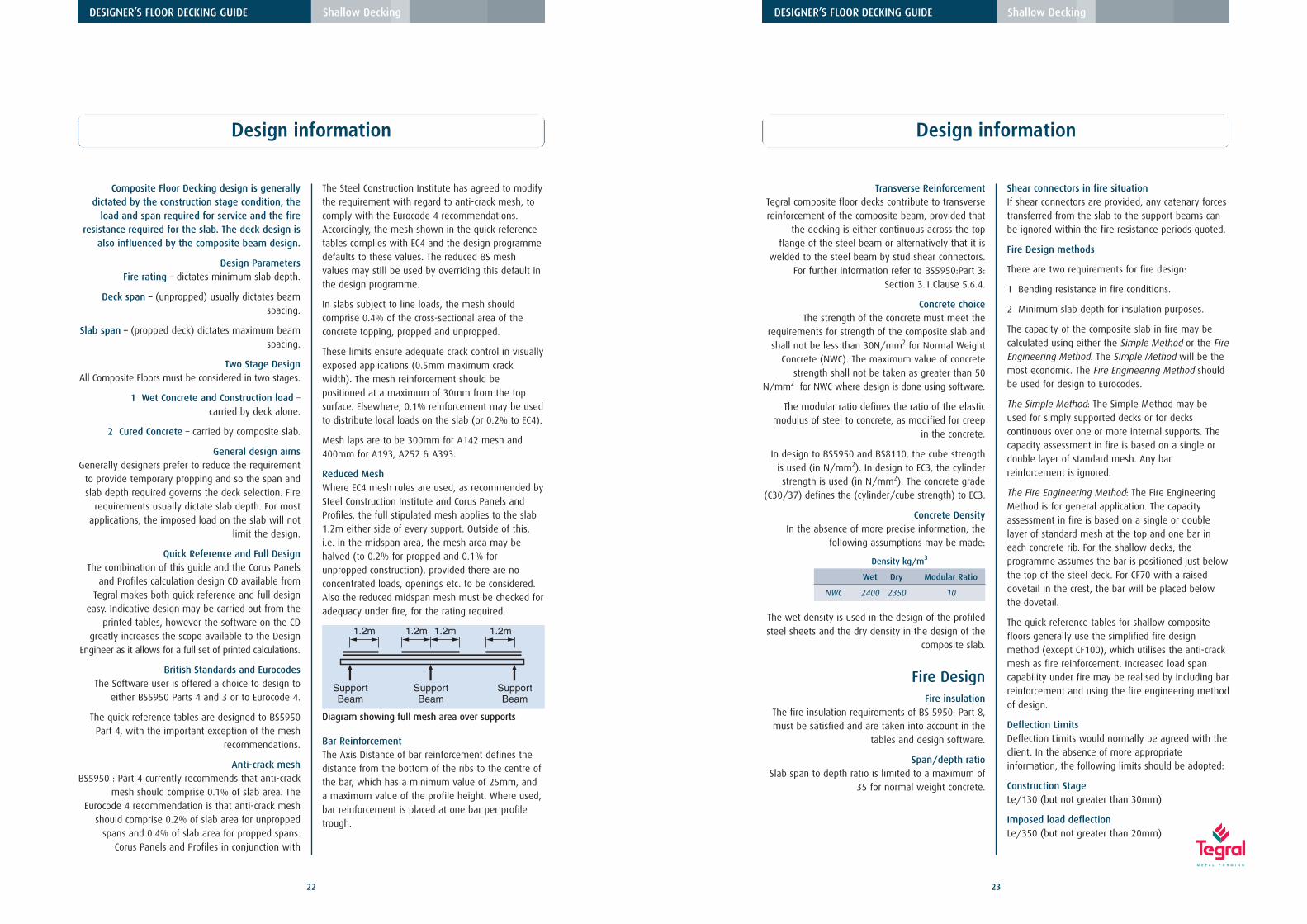
Reduced MeshWhere EC4 mesh rules are used, as recommended bySteel Construction Institute and Corus Panels andProfiles, the full stipulated mesh applies to the slab1.2m either side of every support. Outside of this,i.e. in the midspan area, the mesh area may behalved (to 0.2% for propped and 0.1% forunpropped construction), provided there are noconcentrated loads, openings etc. to be considered.Also the reduced midspan mesh must be checked foradequacy under fire, for the rating required.
Bar ReinforcementThe Axis Distance of bar reinforcement defines thedistance from the bottom of the ribs to the centre ofthe bar, which has a minimum value of 25mm, anda maximum value of the profile height. Where used,bar reinforcement is placed at one bar per profiletrough.
1.2m 1.2m
SupportBeam
SupportBeam
SupportBeam
1.2m 1.2m
Diagram showing full mesh area over supports
23
DESIGNER’S FLOOR DECKING GUIDE Shallow Decking
Transverse ReinforcementTegral composite floor decks contribute to transversereinforcement of the composite beam, provided that
the decking is either continuous across the topflange of the steel beam or alternatively that it is
welded to the steel beam by stud shear connectors.For further information refer to BS5950:Part 3:
Section 3.1.Clause 5.6.4.
Concrete choiceThe strength of the concrete must meet the
requirements for strength of the composite slab andshall not be less than 30N/mm2 for Normal Weight
Concrete (NWC). The maximum value of concretestrength shall not be taken as greater than 50
N/mm2 for NWC where design is done using software.
The modular ratio defines the ratio of the elasticmodulus of steel to concrete, as modified for creep
in the concrete.
In design to BS5950 and BS8110, the cube strengthis used (in N/mm2). In design to EC3, the cylinderstrength is used (in N/mm2). The concrete grade
(C30/37) defines the (cylinder/cube strength) to EC3.
Concrete DensityIn the absence of more precise information, the
following assumptions may be made:
The wet density is used in the design of the profiledsteel sheets and the dry density in the design of the
composite slab.
Fire DesignFire insulation
The fire insulation requirements of BS 5950: Part 8,must be satisfied and are taken into account in the
tables and design software.
Span/depth ratioSlab span to depth ratio is limited to a maximum of
35 for normal weight concrete.
Shear connectors in fire situationIf shear connectors are provided, any catenary forcestransferred from the slab to the support beams canbe ignored within the fire resistance periods quoted.
Fire Design methods
There are two requirements for fire design:
1 Bending resistance in fire conditions.
2 Minimum slab depth for insulation purposes.
The capacity of the composite slab in fire may becalculated using either the Simple Method or the FireEngineering Method. The Simple Method will be themost economic. The Fire Engineering Method shouldbe used for design to Eurocodes.
The Simple Method: The Simple Method may beused for simply supported decks or for deckscontinuous over one or more internal supports. Thecapacity assessment in fire is based on a single ordouble layer of standard mesh. Any barreinforcement is ignored.
The Fire Engineering Method: The Fire EngineeringMethod is for general application. The capacityassessment in fire is based on a single or doublelayer of standard mesh at the top and one bar ineach concrete rib. For the shallow decks, theprogramme assumes the bar is positioned just belowthe top of the steel deck. For CF70 with a raiseddovetail in the crest, the bar will be placed belowthe dovetail.
The quick reference tables for shallow compositefloors generally use the simplified fire designmethod (except CF100), which utilises the anti-crackmesh as fire reinforcement. Increased load spancapability under fire may be realised by including barreinforcement and using the fire engineering methodof design.
Deflection LimitsDeflection Limits would normally be agreed with theclient. In the absence of more appropriateinformation, the following limits should be adopted:
Construction StageLe/130 (but not greater than 30mm)
Imposed load deflectionLe/350 (but not greater than 20mm)
Density kg/m3
Wet Dry Modular Ratio
NWC 2400 2350 10
Design information
24
DESIGNER’S FLOOR DECKING GUIDE Shallow Decking
Total load deflectionLe/250 (but not greater than 30mm)
According to BS5950 Part 4, ponding, resulting fromthe deflection of the decking is only taken into
account if the construction stage deflection exceedsDs/10. Le is the effective span of the deck and Ds is
the slab overall depth (excluding non-structuralscreeds).
The deflection under construction load should notexceed the span/180 or 20mm overall, whichever isthe lesser, when the ponding of the concrete slab isnot taken into account. Where ponding is taken into
account the deflection should not exceed thespan/130 or 30mm overall. The quick reference
tables do take ponding into account, if deflectionexceeds Ds/10, or Le/180, and thus use span/130
or 30mm as a deflection limit.
It is recommended that the prop width should not beless than 100mm otherwise the deck may mark
slightly at prop lines.
VibrationThe dynamic sensitivity of the composite slab shouldbe checked in accordance with the Steel Construction
Institute publication P076: Design guide on thevibration of floors. The natural frequency is
calculated using the self-weight of the slab, ceilingand services, screed and 10% imposed loads,
representing the permanent loads and the floor.
In the absence of more appropriate information, thenatural frequency of the composite slab should notexceed 5Hz for normal office, industrial or domesticusage. Conversely, for dance floor type applications
or for floors supporting sensitive machinery, the limitmay need to be set higher.
For design to the Eurocodes, the loads considered forthe vibration check are increased using the psi-factor
for imposed loads (typically 0.5). The naturalfrequency limit may be reduced to 4Hz, because of
this higher load, used in the calculation.
Loads and Load ArrangementLoading information would normally be agreed with
the clients. Reference should also be made to BS6399 and to EC1.
Factored loads are considered at the ultimate limitstate and unfactored loads at the serviceability limit
state. Unfactored loads are also considered in fireconditions.
Partial factors are taken from BS5950, EC3 and EC4.
Loads considered at the construction stage consist ofthe slab self weight and the basic construction load.The basic construction load is taken as 1.5 kN/m2 or4.5/Lp (whichever is greater), where Lp is the spanof the profiled steel sheets between effectivesupports in metres. For multi span unproppedconstruction, the basic construction load of 1.5kN/m2 is considered over the one span only. Onother spans, the construction load considered is halfthis value (i.e. 0.75 kN/m2). Construction loads areconsidered as imposed loads for this check.
Loads considered at the normal service stage consistof the slab self weight, superimposed dead loadsand imposed loads.
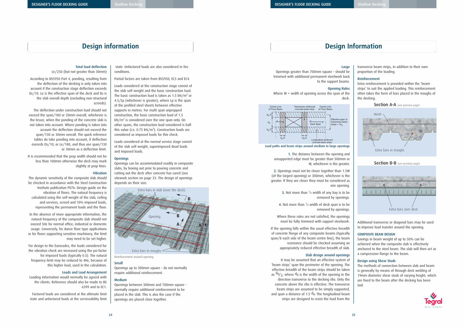
OpeningsOpenings can be accommodated readily in compositeslabs, by boxing out prior to pouring concrete andcutting out the deck after concrete has cured (seesitework section on page 33. The design of openingsdepends on their size:
SmallOpenings up to 300mm square - do not normallyrequire additional reinforcement.
MediumOpenings between 300mm and 700mm square -normally require additional reinforcement to beplaced in the slab. This is also the case if theopenings are placed close together.
Design information
Opening
A
B
B
A
Extra bars in slab (over the deck)
Extra bars in troughs
Reinforcement around opening
25
DESIGNER’S FLOOR DECKING GUIDE Shallow Decking
LargeOpenings greater than 700mm square - should be
trimmed with additional permanent steelwork backto the support beams.
Opening RulesWhere W = width of opening across the span of the
deck.
1. The distance between the opening andunsupported edge must be greater than 500mm or
W, whichever is the greater.
2. Openings must not be closer together than 1.5W(of the largest opening) or 300mm, whichever is thegreater. If they are closer they must be considered as
one opening.
3. Not more than 1/4 width of any bay is to beremoved by openings.
4. Not more than 1/4 width of deck span is to beremoved by openings.
Where these rules are not satisfied, the openingsmust be fully trimmed with support steelwork.
If the opening falls within the usual effective breadthof concrete flange of any composite beams (typicallyspan/8 each side of the beam centre line), the beam
resistance should be checked assuming anappropriately reduced effective breadth of slab.
Slab design around openingsIt may be assumed that an effective system of
‘beam strips’ span the perimeter of the opening. Theeffective breadth of the beam strips should be takenas do/2, where do is the width of the opening in the
direction transverse to the decking ribs. Only theconcrete above the ribs is effective. The transversebeam strips are assumed to be simply supported,
and span a distance of 1.5 do. The longitudinal beamstrips are designed to resist the load from the
transverse beam strips, in addition to their ownproportion of the loading.
ReinforcementExtra reinforcement is provided within the ‘beamstrips’ to suit the applied loading. This reinforcementoften takes the form of bars placed in the troughs ofthe decking.
Additional transverse or diagonal bars may be usedto improve load transfer around the opening.
COMPOSITE BEAM DESIGNSavings in beam weight of up to 50% can beachieved when the composite slab is effectivelyanchored to the steel beam. The slab will then act asa compression flange to the beam.
Design using Shear StudsThe methods of connection between slab and beamis generally by means of through deck welding of19mm diameter shear studs of varying height, whichare fixed to the beam after the decking has beenlaid.
Design Information
Centre Lineof Floor Beam
Centre Lineof Floor Beam
Deck Span
Transverse reinforcedconcrete beam strip
Longitudinal reinforcedconcrete beam strips
Effective span oftransverse beamstrips = 1do
do/2
do/2
do
do/2 do/2
Load paths and beam strips around medium to large openings
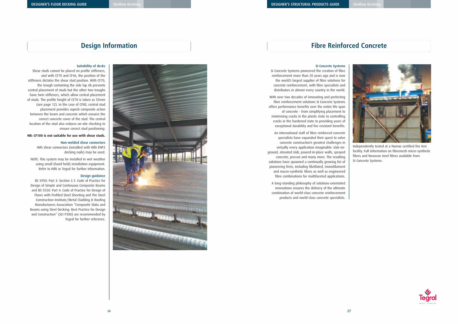
Suitability of decksShear studs cannot be placed on profile stiffeners,
and with CF70 and CF46, the position of thestiffeners dictates the shear stud position. With CF70,
the trough containing the side lap rib preventscentral placement of studs but the other two troughshave twin stiffeners, which allow central placement
of studs. The profile height of CF70 is taken as 55mm(see page 12). In the case of CF80, central stud
placement provides superb composite actionbetween the beam and concrete which ensures the
correct concrete cover of the stud. The centrallocation of the stud also reduces on-site checking to
ensure correct stud positioning.
NB: CF100 is not suitable for use with shear studs.
Non-welded shear connectorsHilti shear connectors (installed with Hilti ENP2
decking nails) may be used.
NOTE: This system may be installed in wet weatherusing small (hand held) installation equipment.
Refer to Hilti or Tegral for further information.
Design guidanceBS 5950: Part 3: Section 3.1: Code of Practice for
Design of Simple and Continuous Composite Beamsand BS 5550: Part 4: Code of Practice for Design of
Floors with Profiled Steel Sheeting and The SteelConstruction Institute/Metal Cladding & Roofing
Manufacturers Association “Composite Slabs andBeams using Steel Decking: Best Practice for Designand Construction” (SCI P300) are recommended by
Tegral for further reference.
Fibre Reinforced Concrete
SI Concrete SystemsSI Concrete Systems pioneered the creation of fibrereinforcement more than 20 years ago and is now
the world’s largest supplier of fibre solutions forconcrete reinforcement, with fibre specialists anddistributors in almost every country in the world.
With over two decades of innovating and perfectingfibre reinforcement solutions SI Concrete Systems
offers performance benefits over the entire life spanof concrete - from simplifying placement to
minimising cracks in the plastic state to controllingcracks in the hardened state to providing years of
exceptional durability and fire resistant benefits.
An international staff of fibre reinforced concretespecialists have expanded their quest to solveconcrete construction’s greatest challenges in
virtually every application imaginable: slab-on-ground, elevated slab, poured-in-place walls, sprayed
concrete, precast and many more. The resultingsolutions have spawned a continually growing list ofpioneering firsts, including fibrillated, monofilament
and macro-synthetic fibres as well as engineeredfibre combinations for multifaceted applications.
A long-standing philosophy of solutions-orientatedinnovations ensures the delivery of the ultimate
combination of world-class concrete reinforcementproducts and world-class concrete specialists.
Independently tested at a Namas certified fire testfacility. Full information on fibremesh micro-syntheticfibres and Novocon steel fibres available from SI Concrete Systems.
29
DESIGNER’S FLOOR DECKING GUIDE Shallow Decking
28
DESIGNER’S FLOOR DECKING GUIDE Shallow Decking
Construction Details - CF46, CF51, CF60, CF80, CF100 Construction Details - CF46, CF51, CF60, CF80, CF100
Edge trim reference
Indicates cut plate245 mm wide
Indicates cut deck
Edge trimdimensions
F75
F75
Distance (mm)from centreline of tie member to Setting OutPoint (s.o.p.)of deckingfirst sheet.
X = distance (mm) from centreline ofbeam to edge of slab (parallel to deck span)
Y = distance (mm)from centreline of tie member to edge of slab (perpendicularto deck span)
Indicates baywhich requirestemporarypropping.
94
245C P
F75
F75
X X
Beammember
centreline
Tiemember
dimensions
Y
Y
C D
6-10002107
Plan view of typical floor layout Deck notation
Number of sheets
Bundle number
PhaseFloor level
Span of decking
6-10002107
Decking lengths
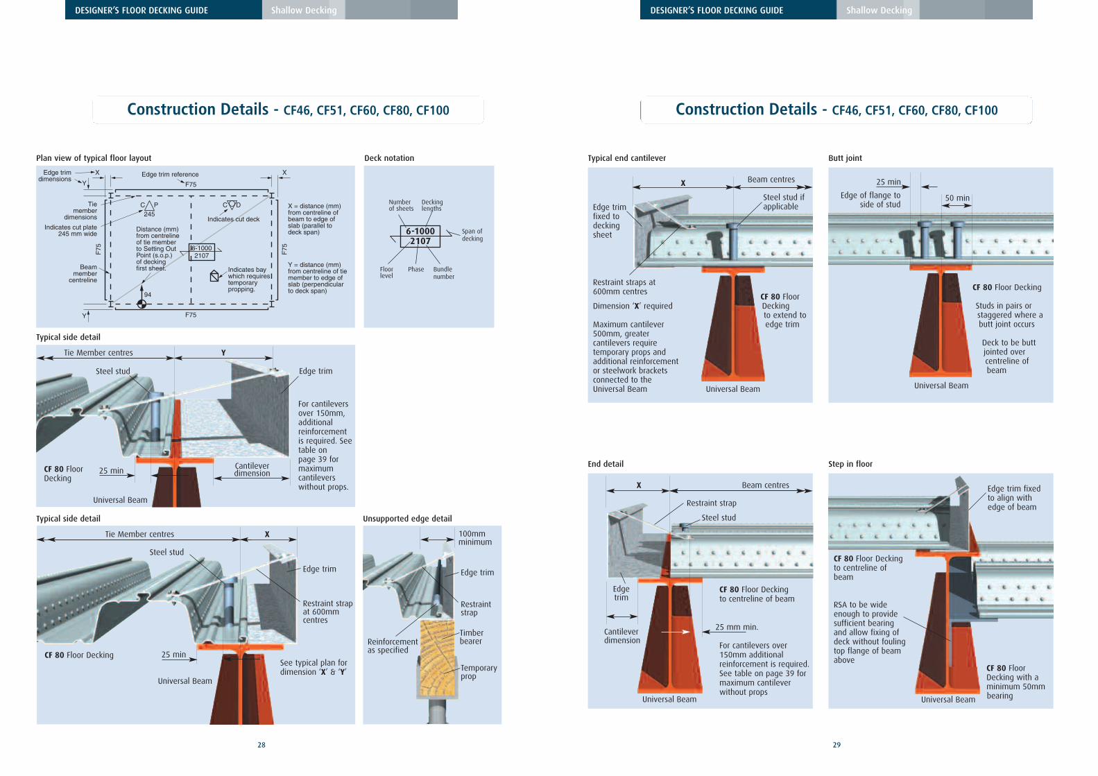
Typical side detail
CF 80 FloorDecking
YTie Member centres
For cantileversover 150mm,additionalreinforcementis required. Seetable on page 39 formaximumcantileverswithout props.
See typical plan fordimension ‘X’ & ‘Y’
Universal Beam
Edge trim
Cantileverdimension
Steel stud
25 min
Typical side detail Unsupported edge detail
CF 80 Floor Decking
XTie Member centres
Universal Beam
Edge trim
Restraint strapat 600mmcentres
Steel stud
25 min
Edge trim
Restraintstrap
Temporaryprop
Reinforcementas specified
100mmminimum
Timberbearer
50 min
Butt jointTypical end cantilever
Step in floor
CF 80 Floor Decking
Studs in pairs orstaggered where abutt joint occurs
Deck to be buttjointed overcentreline of beam
Edge of flange toside of stud
X Beam centres
Restraint straps at600mm centres
Universal Beam Universal Beam
25 min
CF 80 FloorDecking to extend toedge trim
CF 80 Floor Decking to centreline ofbeam
RSA to be wideenough to providesufficient bearingand allow fixing ofdeck without foulingtop flange of beamabove
CF 80 FloorDecking with aminimum 50mmbearing
Dimension ‘X’ required
Maximum cantilever500mm, greater cantilevers requiretemporary props andadditional reinforcement or steelwork bracketsconnected to the Universal Beam
Steel stud ifapplicableEdge trim
fixed todeckingsheet
Edge trim fixedto align withedge of beam
Universal Beam
End detail
Universal Beam
CF 80 Floor Decking to centreline of beam
For cantilevers over150mm additionalreinforcement is required.See table on page 39 formaximum cantileverwithout props
X
25 mm min.
Beam centres
Edgetrim
Steel stud
Restraint strap
Cantileverdimension
31
DESIGNER’S FLOOR DECKING GUIDE Shallow Decking
30
DESIGNER’S FLOOR DECKING GUIDE Shallow Decking
Construction Details - CF46, CF51, CF60, CF80, CF100 Construction Details - CF46, CF51, CF60, CF80, CF100
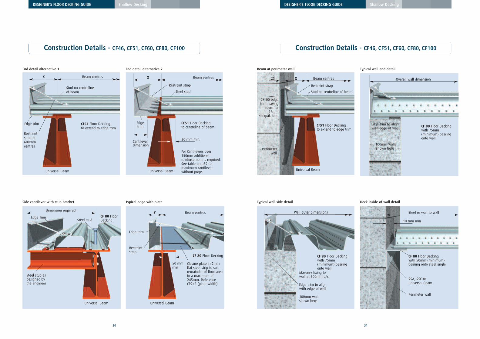
End detail alternative 1 End detail alternative 2
Universal Beam
CF51 Floor Decking to extend to edge trim
X Beam centres
Edge trim
Stud on centrelineof beam
Restraintstrap at600mmcentres
Universal Beam
CF51 Floor Decking to centreline of beam
For Cantilevers over150mm additionalreinforcement is required.See table on p39 formaximum cantileverwithout props
X
20 mm min.
Beam centres
Edgetrim
Steel stud
Restraint strap
Cantileverdimension
Beam at perimeter wall
Universal Beam
Perimeterwall
CF51 Floor Decking to extend to edge trim
X25 Beam centres
CE100 edgetrim leaving
room for25mm
Korkpak joint
Stud on centreline of beam
Restraint strap
Side cantilever with stub bracket Typical edge with plate
Universal Beam
CF 80 FloorDecking
Steel stub asdesigned bythe engineer
Edge Trim
Dimension required
Steel stud
Universal Beam
CF 80 Floor Decking
Closure plate in 2mmflat steel strip to suitremainder of floor areato a maximum of245mm. ReferenceCP245 (plate width)
Y Beam centres
Edge trim
Restraintstrap
50 mmmin
Typical wall end detail
CF 80 Floor Decking with 75mm(minimum) bearingonto wall
Overall wall dimension
Edge trim to alignwith edge of wall
100mm wallshown here
Typical wall side detail
CF 80 Floor Decking with 75mm(minimum) bearingonto wall
Masonry fixing to wall at 500mm c/c
Edge trim to align with edge of wall
100mm wallshown here
Wall outer dimensions
Deck inside of wall detail
CF 80 Floor Decking with 50mm (minimum)bearing onto steel angle
Steel or wall to wall
10 mm min
Perimeter wall
RSA, RSC orUniversal Beam
33
DESIGNER’S FLOOR DECKING GUIDE Shallow Decking
32
DESIGNER’S FLOOR DECKING GUIDE Shallow Decking
Site Work Site Work
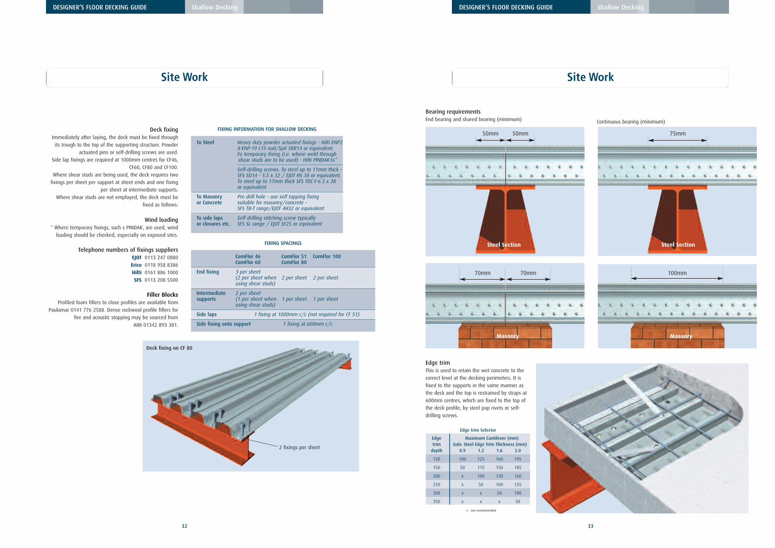
FIXING INFORMATION FOR SHALLOW DECKING
To Steel Heavy duty powder actuated fixings - Hilti ENP2X-ENP-19 L15 nail/Spit SBR14 or equivalent. Fo temporary fixing (i.e. where weld through shear studs are to be used) - Hilti PINDAK16*
Self-drilling screws. To steel up to 11mm thick -SFS SD14 - 5.5 x 32 / EJOT HS 38 or equivalent. To steel up to 17mm thick SFS TDC-T-6.3 x 38 or equivalent
To Masonry Pre drill hole - use self tapping fixing or Concrete suitable for masonry/concrete -
SFS TB-T range/EJOT 4H32 or equivalent
To side laps Self drilling stitching screw typically or closures etc. SFS SL range / EJOT SF25 or equivalent
End fixing 3 per sheet(2 per sheet when 2 per sheet 2 per sheetusing shear studs)
Intermediate 2 per sheetsupports (1 per sheet when 1 per sheet 1 per sheet
using shear studs)
Side laps 1 fixing at 1000mm c/c (not required for CF 51)
Side fixing onto support 1 fixing at 600mm c/c
Deck fixingImmediately after laying, the deck must be fixed through
its trough to the top of the supporting structure. Powder
actuated pins or self-drilling screws are used.
Side lap fixings are required at 1000mm centres for CF46,
CF60, CF80 and CF100.
Where shear studs are being used, the deck requires two
fixings per sheet per support at sheet ends and one fixing
per sheet at intermediate supports.
Where shear studs are not employed, the deck must be
fixed as follows:
Wind loading* Where temporary fixings, such s PINDAK, are used, wind
loading should be checked, especially on exposed sites.
Telephone numbers of fixings suppliersEJOT 0113 247 0880
Erico 0118 958 8386
Hilti 0161 886 1000
SFS 0113 208 5500
Filler BlocksProfiled foam fillers to close profiles are available from
Paulamar 0141 776 2588. Dense rockwool profile fillers for
fire and acoustic stopping may be sourced from
AIM 01342 893 381.
Edge trimThis is used to retain the wet concrete to the
correct level at the decking perimeters. It is
fixed to the supports in the same manner as
the deck and the top is restrained by straps at
600mm centres, which are fixed to the top of
the deck profile, by steel pop rivets or self-
drilling screws.
2 fixings per sheet
Deck fixing on CF 80
Bearing requirementsEnd bearing and shared bearing (minimum) Continuous bearing (minimum)
50mm
Steel Section
50mm
Steel Section
75mm
70mm
Masonry
70mm
Masonry
100mm
Edge trim Selector
Edge Maximum Cantilever (mm)trim Galv. Steel Edge Trim Thickness (mm)
depth 0.9 1.2 1.6 2.0
130 100 125 160 195
150 50 115 150 185
200 x 100 130 160
250 x 50 100 135
300 x x 50 100
350 x x x 50
x - not recommended
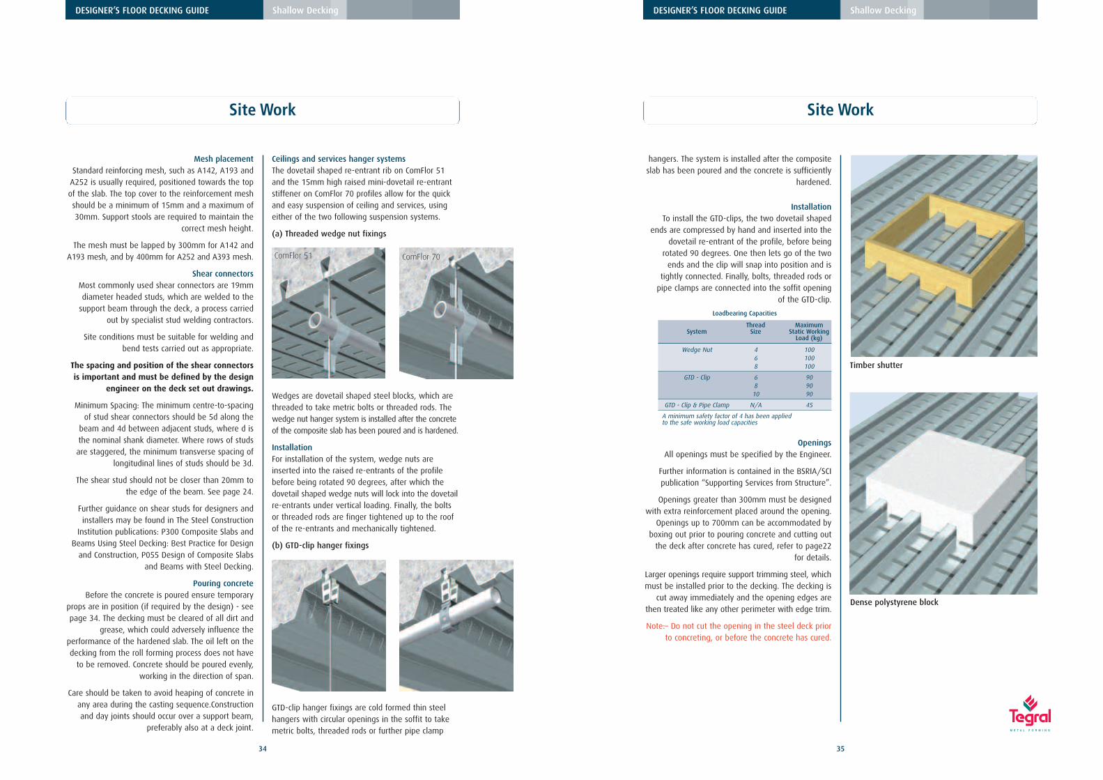
Ceilings and services hanger systemsThe dovetail shaped re-entrant rib on ComFlor 51and the 15mm high raised mini-dovetail re-entrantstiffener on ComFlor 70 profiles allow for the quickand easy suspension of ceiling and services, usingeither of the two following suspension systems.
(a) Threaded wedge nut fixings
Wedges are dovetail shaped steel blocks, which arethreaded to take metric bolts or threaded rods. Thewedge nut hanger system is installed after the concreteof the composite slab has been poured and is hardened.
InstallationFor installation of the system, wedge nuts areinserted into the raised re-entrants of the profilebefore being rotated 90 degrees, after which thedovetail shaped wedge nuts will lock into the dovetailre-entrants under vertical loading. Finally, the boltsor threaded rods are finger tightened up to the roofof the re-entrants and mechanically tightened.
(b) GTD-clip hanger fixings
GTD-clip hanger fixings are cold formed thin steelhangers with circular openings in the soffit to takemetric bolts, threaded rods or further pipe clamp
35
DESIGNER’S FLOOR DECKING GUIDE Shallow Decking
34
DESIGNER’S FLOOR DECKING GUIDE Shallow Decking
Mesh placementStandard reinforcing mesh, such as A142, A193 and
A252 is usually required, positioned towards the topof the slab. The top cover to the reinforcement meshshould be a minimum of 15mm and a maximum of30mm. Support stools are required to maintain the
correct mesh height.
The mesh must be lapped by 300mm for A142 andA193 mesh, and by 400mm for A252 and A393 mesh.
Shear connectorsMost commonly used shear connectors are 19mmdiameter headed studs, which are welded to the
support beam through the deck, a process carriedout by specialist stud welding contractors.
Site conditions must be suitable for welding andbend tests carried out as appropriate.
The spacing and position of the shear connectorsis important and must be defined by the design
engineer on the deck set out drawings.
Minimum Spacing: The minimum centre-to-spacingof stud shear connectors should be 5d along the
beam and 4d between adjacent studs, where d isthe nominal shank diameter. Where rows of studsare staggered, the minimum transverse spacing of
longitudinal lines of studs should be 3d.
The shear stud should not be closer than 20mm tothe edge of the beam. See page 24.
Further guidance on shear studs for designers andinstallers may be found in The Steel Construction
Institution publications: P300 Composite Slabs andBeams Using Steel Decking: Best Practice for Design
and Construction, P055 Design of Composite Slabsand Beams with Steel Decking.
Pouring concreteBefore the concrete is poured ensure temporary
props are in position (if required by the design) - seepage 34. The decking must be cleared of all dirt and
grease, which could adversely influence theperformance of the hardened slab. The oil left on thedecking from the roll forming process does not have
to be removed. Concrete should be poured evenly,working in the direction of span.
Care should be taken to avoid heaping of concrete inany area during the casting sequence.Constructionand day joints should occur over a support beam,
preferably also at a deck joint.
hangers. The system is installed after the compositeslab has been poured and the concrete is sufficiently
hardened.
InstallationTo install the GTD-clips, the two dovetail shaped
ends are compressed by hand and inserted into thedovetail re-entrant of the profile, before being
rotated 90 degrees. One then lets go of the twoends and the clip will snap into position and is
tightly connected. Finally, bolts, threaded rods orpipe clamps are connected into the soffit opening
of the GTD-clip.
OpeningsAll openings must be specified by the Engineer.
Further information is contained in the BSRIA/SCIpublication “Supporting Services from Structure”.
Openings greater than 300mm must be designedwith extra reinforcement placed around the opening.
Openings up to 700mm can be accommodated byboxing out prior to pouring concrete and cutting out
the deck after concrete has cured, refer to page22 for details.
Larger openings require support trimming steel, whichmust be installed prior to the decking. The decking is
cut away immediately and the opening edges arethen treated like any other perimeter with edge trim.
Note:– Do not cut the opening in the steel deck priorto concreting, or before the concrete has cured.
Site Work Site Work
ComFlor 51 ComFlor 70
Loadbearing Capacities
Thread MaximumSystem Size Static Working
Load (kg)
Wedge Nut 4 1006 1008 100
GTD - Clip 6 908 9010 90
GTD - Clip & Pipe Clamp N/A 45
A minimum safety factor of 4 has been applied to the safe working load capacities
Timber shutter
Dense polystyrene block
37
Tegral Deep Decking
36
DESIGNER’S FLOOR DECKING GUIDE Shallow Decking
Site Work
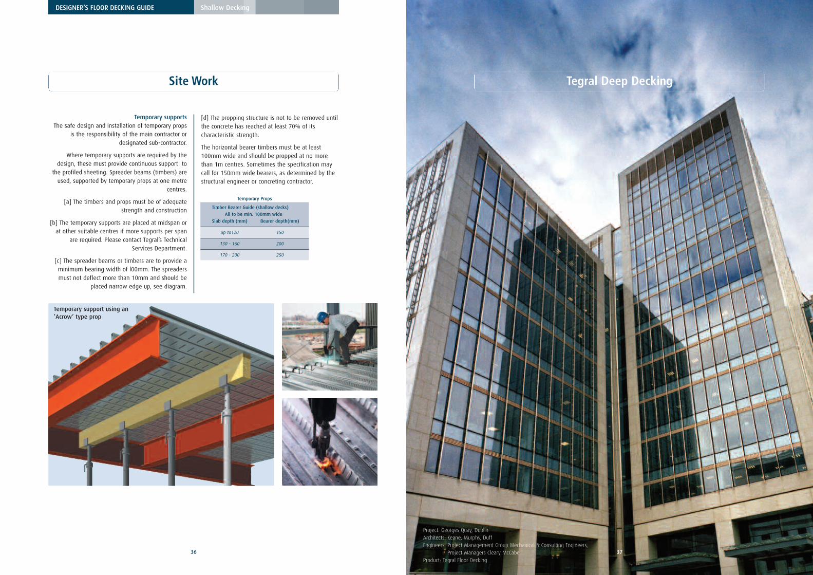
Temporary support using an’Acrow’ type prop
Temporary supportsThe safe design and installation of temporary props
is the responsibility of the main contractor ordesignated sub-contractor.
Where temporary supports are required by thedesign, these must provide continuous support to
the profiled sheeting. Spreader beams (timbers) areused, supported by temporary props at one metre
centres.
[a] The timbers and props must be of adequatestrength and construction
[b] The temporary supports are placed at midspan orat other suitable centres if more supports per span
are required. Please contact Tegral’s TechnicalServices Department.
[c] The spreader beams or timbers are to provide aminimum bearing width of l00mm. The spreadersmust not deflect more than 10mm and should be
placed narrow edge up, see diagram.
[d] The propping structure is not to be removed untilthe concrete has reached at least 70% of itscharacteristic strength.
The horizontal bearer timbers must be at least100mm wide and should be propped at no morethan 1m centres. Sometimes the specification maycall for 150mm wide bearers, as determined by thestructural engineer or concreting contractor.
Temporary Props
Timber Bearer Guide (shallow decks)
All to be min. 100mm wide
Slab depth (mm) Bearer depth(mm)
up to120 150
130 - 160 200
170 - 200 250
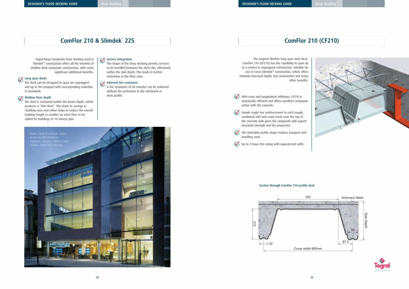
Project: Georges Quay, DublinArchitects: Keane, Murphy, DuffEngineers: Project Management Group Mechanical & Consulting Engineers,
With cross and longitudinal stiffeners, CF210 isstructurally efficient and offers excellent compositeaction with the concrete.
Simple single bar reinforcement in each trough,combined with anti-crack mesh near the top ofthe concrete slab gives the composite slab superbstructural strength and fire properties.
The Stackable profile shape reduces transport andhandling costs.
Up to 2 hours fire rating with unprotected soffit.
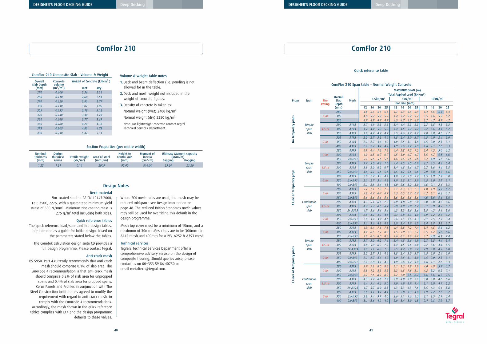
ComFlor 210 (CF210)
The original SlimFlor long span steel deck, ComFlor 210 (CF210) has the capability to span up to 6 metres in unpropped construction. Suitable for
use in Corus Slimdek® construction, which offersminimal structural depth, fast construction and many
other benefits.
DESIGNER’S FLOOR DECKING GUIDE Deep Decking
87.5
56
52
1
Slab
Dep
th
210
Cover width 600mm
425
S
Anticrack Mesh
Section through ComFlor 210 profile deck
ComFlor 210 & Slimdek®
225
38
DESIGNER’S FLOOR DECKING GUIDE Floor Decking
Tegral Deep Composite Floor decking used inSlimdek® construction offers all the benefits of
shallow deck composite construction, with somesignificant additional benefits.
Long span decks The deck can be designed to span 6m unproppedand up to 9m propped with corresponding reductionin steelwork.
Shallow floor depth The deck is contained within the beam depth, whichproduces a “slim floor”. This leads to savings incladding costs and either helps to reduce the overallbuilding height or enables an extra floor to beadded for buildings of 10 storeys plus.
Service integration The shape of the deep decking permits servicesto be installed between the deck ribs, effectivelywithin the slab depth. This leads to furtherreductions in the floor zone.
Inherent fire resistanceA fire resistance of 60 minutes can be achievedwithout fire protection to the steelwork or deck profile.
Project: Bank of Scotland, DublinArchitects: RKD ArchitectsEngineers: O’Connor, Sutton, CroninProduct: Tegral Floor Decking
40
DESIGNER’S FLOOR DECKING GUIDE Deep Decking
ComFlor 210
ComFlor 210 Composite Slab - Volume & Weight
Overall Concrete Weight of Concrete (kN/m2 )Slab Depth volume
(mm) (m3/m2) Wet Dry
270 0.100 2.36 2.31
280 0.110 2.60 2.54
290 0.120 2.83 2.77
300 0.130 3.07 3.00
305 0.135 3.18 3.12
310 0.140 3.30 3.23
330 0.160 3.77 3.69
350 0.180 4.24 4.16
375 0.205 4.83 4.73
400 0.230 5.42 5.31
Volume & weight table notes
1.Deck and beam deflection (i.e. ponding is notallowed for in the table.
2.Deck and mesh weight not included in theweight of concrete figures.
3.Density of concrete is taken as:
Normal weight (wet) 2400 kg/m2
Normal weight (dry) 2350 kg/m2
Note: For lightweight concrete contact TegralTechnical Services Department.
Section Properties (per metre width)
Nominal Design Height to Moment of Ultimate Moment capacitythickness thickness Profile weight Area of steel neutral axis inertia (kNm/m)
Deck materialZinc coated steel to BS EN 10147:2000,
Fe E 350G, Z275, with a guaranteed minimum yieldstress of 350 N/mm2. Minimum zinc coating mass is
275 g/m2 total including both sides.
Quick reference tablesThe quick reference load/span and fire design tables,
are intended as a guide for initial design, based onthe parameters stated below the tables.
The Comdek calculation design suite CD provides afull design programme. Please contact Tegral.
Anti-crack meshBS 5950: Part 4 currently recommends that anti-crack
mesh should comprise 0.1% of slab area. TheEurocode 4 recommendation is that anti-crack mesh
should comprise 0.2% of slab area for unproppedspans and 0.4% of slab area for propped spans.
Corus Panels and Profiles in conjunction with TheSteel Construction Institute has agreed to modify the
requirement with regard to anti-crack mesh, tocomply with the Eurocode 4 recommendations.
Accordingly, the mesh shown in the quick referencetables complies with EC4 and the design programme
defaults to these values.
Where EC4 mesh rules are used, the mesh may bereduced midspan - see Design Information on page 48. The reduced British Standards mesh valuesmay still be used by overriding this default in thedesign programme.
Mesh top cover must be a minimum of 15mm, and amaximum of 30mm. Mesh laps are to be 300mm forA142 mesh and 400mm for A193, A252 & A393 mesh.
Technical servicesTegral’s Technical Services Department offer acomprehensive advisory service on the design ofcomposite flooring, Should queries arise, pleasecontact us on 00+353 59 86 40750 or email [email protected].
43
DESIGNER’S FLOOR DECKING GUIDE Deep Decking
SD225 deck is a state of the art cold-formedprofile design offering fully optimised compositeand load carrying characteristics.
The re-entrant section to the top flange of theprofile enhances composite action and offerseasy services attachment.
The deck is designed to offer flexible serviceintegration (as described in Steel ConstructionInstitute publication “Service Integration inSlimdek®”).
Up to 2 hours fire rating with unprotected soffit.
Slimdek®
225 (SD225)
Slimdek® 225 (SD225) is an important addition toTegral’s flooring range. Developed specifically for the
Corus Slimdek® system, SD225 offers up to 6.5metres unpropped span.
Corus Slimdek® engineered flooring solution is aunique structural floor system which uses
Asymmetric SlimFlor Beams, where the bottomflange is wider than the top flange.
The SD225 steel deck bears on the lower flange ofthe beam which results in a minimal overall floor
depth, the concrete that surrounds the beamprovides composite action without the need for
shear studs, and fire protection to the beam.
The Slimdek® system is fast, normallyeliminates temporary props, is structurallyoptimised and saves on cladding costs.
The system also reduces building height orenables extra floors to be built.
Anticrack Mesh
37.5
19530
37.5
27.5
Cover width 600mm
238
8
400
500
100
32.6
27.5
32.6
5
42
ComFlor 210
DESIGNER’S FLOOR DECKING GUIDE Deep Decking
Parameters assumed for quick reference span tables
Mesh: See notes on page 38.
Spans: Measured centre to centre of supports.
Deck: Standard deck material specification (see
page 38).
Bearing width: The width of the support is assumed to be
200mm.
Prop width: Assumed to be 100mm.
Deflection: Construction stage L/130 or 30mm
(ponding has been taken into account).
Deflection: Composite stage L/350.
Concrete grade: The concrete is to be Grade 35 with a
maximum aggregate size of 20mm. The wet
weight of concrete is taken to be normal
weight 2400kg/m3. The modular ratio is 10.
Lightweight concrete may be used, please
consult Tegral.
Construction load: 1.5 kN/m2 construction load is taken into
account,in accordance with BS 5950:Part 4.
No allowance is made for heaping of
concrete during the pouring operation.
See design notes.
Slab Depth: The depth of slab is measured from the top
of the concrete to the base of the profile.
Bar reinforcement: End Anchorage for bar reinforcement.
All cases require properly anchored L-bars at
the supports, except for those boxed in red.
Cases boxed in red may have straight bars,
with an anchorage length of 70mm from
the edge of the support. See Design Notes
on page 47 for further information.
One bar is placed in each profile trough, the
cover to deck soffit is assumed at 70mm.
Fire: The Fire Engineering method (FE) has been
used to calculate the reinforcement needed
to achieve the fire rating.
The minimum slab thickness indicated in
each table for each fire rating satisfies the
fire insulation requirements of BS 5950: Part 8.
Span/depth ratio: This is limited to 35 for normal weight
concrete.
Project: Georges Quay, DublinArchitects: Keane, Murphy, DuffEngineers: Project Management Group Mechanical & Consulting Engineers,
Deck materialZinc coated steel to BS EN 10147:2000,
Fe E 350G, Z275, with a guaranteed minimum yieldstress of 350 N/mm2. Minimum zinc coating mass is
275 g/m2 total including both sides.
Quick reference tablesThe quick reference load/span and fire design tables,
are intended as a guide for initial design, based onthe parameters stated below the tables.
The Comdek calculation design suite CD provides afull design programme. Please contact Tegral.
Anti-crack meshBS 5950: Part 4 currently recommends that anti-crack
mesh should comprise 0.1% of slab area. TheEurocode 4 recommendation is that anti-crack mesh
should comprise 0.2% of slab area for unproppedspans and 0.4% of slab area for propped spans.
Corus Panels and Profiles in conjunction with TheSteel Construction Institute has agreed to modify the
requirement with regard to anti-crack mesh, tocomply with the Eurocode 4 recommendations.
Accordingly, the mesh shown in the quick referencetables complies with EC4 and the design programme
defaults to these values.
Where EC4 mesh rules are used, the mesh may bereduced midspan - see Design Information on page 48. The reduced British Standards mesh valuesmay still be used by overriding this default in thedesign programme.
Mesh top cover must be a minimum of 15mm, and amaximum of 30mm. Mesh laps are to be 300mm forA142 mesh and 400mm for A193, A252 & A393 mesh.
Technical servicesTegral’s Technical Services Department offer acomprehensive advisory service on the design ofcomposite flooring, Should queries arise, pleasecontact us on 00+353 59 86 40750 or email [email protected].
47
DESIGNER’S FLOOR DECKING GUIDE Deep Decking
46
DESIGNER’S FLOOR DECKING GUIDE Deep Decking
SD225 Design Information
Deep Composite Floor Decks are used where longerspan (4m plus) floor slabs are required. When
combined with the Corus Slimdek® system, deepdecks are designed to achieve a very shallow
overall structural floor-hence the term Slim FloorConstruction.
Deep DeckingTegral Deep Composite Floor Decks can be used in
one of these applications:
1. Corus Slimdek® system.
2. Long span composite concrete/steel floor deck insteel construction.
3. Long span composite concrete/steel floor deck inmasonry construction.
The design considerations relating to the decking aresimilar for all these applications.
Corus Slimdek® SystemThe most recent slim floor development produced byCorus is the Slimdek® system. This system comprises
Asymmetric Slimflor® beams and deep SD225decking.
The principle of Slimdek® is that the steel deck (andthus the composite concrete slab) bears on the lowerflange of the beam, thus containing the beam within
the floor slab.
Three different types of Slimflor® beam are produced:
Asymmetric Slimflor® Beam (ASB), which is a hotrolled section with a narrower top flange thanbottom flange.
Slimflor® Fabricated Beam (SFB), which is a UniversalColumn section with a wide flange plate welded toits underside.
Rectangular Hollow Slimflor® Beam (RHSFB), which is a rectangular hollow section with a flangeplate welded to its lower face (generally used foredge beams).
Parameters assumed for quick reference span tables
Mesh: See notes on page 42.
Spans: Measured centre to centre of supports.
Deck: Standard deck material specification (see
page 42).
Bearing width: The width of the support is assumed to be
200mm.
Prop width: Assumed to be 100mm.
Deflection: Construction stage L/130 or 30mm
(ponding has been taken into account).
Deflection: Composite stage L/350.
Concrete grade: The concrete is to be Grade 35 with a
maximum aggregate size of 20mm. The wet
weight of concrete is taken to be normal
weight 2400kg/m3. The modular ratio is 10.
Lightweight concrete may be used, please
consult Tegral.
Construction load: 1.5 kN/m2 construction load is taken into
account,in accordance with BS 5950:Part 4.
No allowance is made for heaping of
concrete during the pouring operation.
See design notes.
Slab Depth: The depth of slab is measured from the top
of the concrete to the base of the profile.
Bar reinforcement: End Anchorage for bar reinforcement.
All cases require properly anchored L-bars at
the supports, except for those boxed in red.
Cases boxed in red may have straight bars,
with an anchorage length of 70mm from
the edge of the support. See Design Notes
on page 47 for further information.
One bar is placed in each profile trough, the
cover to deck soffit is assumed at 70mm.
Fire: The Fire Engineering method (FE) has been
used to calculate the reinforcement needed
to achieve the fire rating.
The minimum slab thickness indicated in
each table for each fire rating satisfies the
fire insulation requirements of BS 5950: Part 8.
Span/depth ratio: This is limited to 35 for normal weight
concrete.
Three different types of Slimflor® beam are produced:
1.
2.
3.
49
DESIGNER’S FLOOR DECKING GUIDE Deep Decking
48
DESIGNER’S FLOOR DECKING GUIDE Deep Decking
Slimdek® Design ProcedureThere are two distinct stages for which the elementsof the Slimdek® system must be designed. The first
is the construction stage, during which the beamsand decking support the loads as non-composite
sections. The second is the final stage, during whichthe decking and concrete act together to form
composite slabs, as do (generally) the ASBs and slab.SFBs and RHSFBs will act compositely if shear studs
have been provided.
The key design points are:● Consideration of the required spans will allow the
depth of the beams to be determined.
● Consideration of the required fire resistance willallow the depth of slab to be determined, as a
function of the cover required for the beams andthe decking.
Having established these scheme design parameters,detailed design of the beams and slab can be
undertaken. The following slab depths should beconsidered as typical:
280 ASB sections - 290-320mm deep slab300 ASB sections - 315-340mm deep slab.
These depths will provide adequate cover to the ASBfor it to act compositely with the slab. For SFBs a
greater range of slab depths may be considered for agiven depth of beam; the slab depth requirement
will depend on whether shear studs must beaccommodated to make the SFB act compositely.
Slimdek® Beam DesignThe design of the beams in the Slimdek® system is
presented in The Corus Slimdek® Manual and DesignSoftware which is available from Corus. Further
detailed design information is available in The SteelConstruction Institute publications: P300 CompositeSlabs and Beams Using Steel Decking: Best Practice
for Design and Construction, P055 Design ofComposite Slabs and Beams with Steel Decking.
Please see references section for further information.
Decking DesignIn addition to considering the self-weight of the slab,
the design of the deep decking should take intoaccount temporary construction loads. These
construction loads differ slightly from those thatshould be considered for shallow decking, because
of the considerably greater spans that can beachieved with deep decking.
Construction Stage LoadingThe 1.5 kN/m2 construction load required by BS5950-4 should only be applied over the middle 3mof the span, as shown above.
A reduced load of 0.75 kN/m2 (as specified in EC4)may be applied outside this region, as it would beoverly conservative to apply the full load of1.5kN/m2 over the entire span. The effect ofconcrete ponding should be taken into account (byincreasing the self weight of the slab) if thedeflection under self-weight alone exceeds the lesserof span/180 or 20mm.
If temporary props are used to support the deckingduring construction, a construction load of 1.5 kN/m2
should be considered as acting over the completespan (between permanent supports). Although alower value might be justifiable over parts of thespan, a constant load should be considered fordesign simplicity.
Temporary propping (when required)The spacing of temporary props is governed by theability of the decking to resist combined bending andshear in the hogging (negative) moment regionsover the lines of props. It is recommended that thespacing between the props should be relativelyclose, so that local loads do not cause damage to thedecking (2.5m to 3.5m spacing depending on theslab weight). A 100 mm wide timber bearer shouldbe used to distribute the load at these points.
End BearingThe end bearing of the sheets should be specified as50mm. The flange widths are such that this bearingcan be achieved, whilst still allowing the sheets to
be dropped vertically into position (i.e. withouthaving to ‘thread’ them between the top and
bottom flanges).
Slab DesignThe design of composite slabs using deep decking
differs from that for shallow decking in thefollowing ways:
1. Placing bar reinforcement in the troughs of thedecking increases the ultimate load resistance of theslab. The benefit of these bars is considered in both
the ‘normal’ and fire conditions.
2. The slab depth may need to be chosen not only tosatisfy the structural, durability and fire resistancerequirements of the slab itself, but also to provide
appropriate cover over ASB or Slimflor beams.
3. The reinforcing bars in the troughs of the deckingprovide additional tensile area to that provided by
the decking, and thus enhance the bendingresistance of the composite slab.
4. Bar diameters range from 8mm to 32mm,depending on the span and fire resistance
requirements.
5. Straight bars may be used to achieve 60 minutesfire resistance (provided that shear stresses are low).
In other cases, L bars should be used to providesufficient end anchorage in fire conditions.
CrackingIt is normal for some cracking to occur in the slabover the beams. These cracks run parallel with thebeams and are not detrimental to the structuralbehaviour of the slab. They may be controlled bymesh reinforcement provided across the tops of thebeams. Guidance on the detailing of reinforcementto control cracking may be found in the CorusSlimdek® manual.
Additional reinforcement may be required to fulfilthe following roles:
● Transverse reinforcement adjacent to shear connectors.
● U-bars at composite edge beams.
● Additional crack control reinforcements
● Strengthening around openings.
● Strengthening at positions of concentrated loads.
Fire Resistance
One of the principal considerations governing thechoice of slab depth is the required fire resistanceperiod. Minimum depths are given above as afunction of the concrete type and fire resistancerequired and are based on insulation requirements.
The Fire Engineering Method: The capacityassessment in fire is based on a single or doublelayer of standard mesh at the top and one bar ineach concrete rib. For CF210 or SD 225 decking, thebar is placed at an axis distance, dependent on thefire resistance period. The axis distance must not beless than 70mm. To maximise fire resistance capacitythe axis distance needs to be 70, 90 and 120mm(from the soffit of the deck) for 60, 90 and 120mins. fire resistance, respectively. However wherefire resistance is not the limiting factor it may bemore effective for the axis distance to be at theminimum.
Reduced MeshWhere EC4 mesh rules are used, as recommended byThe Steel Construction Institute and Corus Panels andProfiles , the full stipulated mesh applies to the slab
1.2m either side of every support. Outside of this,i.e. in the midspan area, the mesh area may be
halved (to 0.2% for propped and 0.1% forunpropped construction), provided there are no
concentrated loads, openings etc. to be considered.Also the reduced midspan mesh must be checked for
adequacy under fire, for the rating required.
VibrationThe dynamic sensitivity of the composite slab should
be checked in accordance with the SCI publicationP076: Design guide on the vibration of floors. The
natural frequency is calculated using the self-weightof the slab, ceiling and services, screed and 10%
imposed loads, representing the permanent loadsand the floor self weight.
In the absence of more appropriate information, thenatural frequency of the composite slab should notexceed 5Hz for normal office, industrial or domestic
usage. For designs using SD225 or CF210 decking,this limit may be reduced to 4Hz if the design has
been carried out on the assumption of simplesupports at the ends. Conversely, for dance floor type
applications or for floors supporting sensitivemachinery, the limit may need to be set higher.
In the Slimdek® system, consideration should begiven to the system frequency of the floor as a
whole if the natural frequency of the slab and/orthe supporting beam is less than 5Hz.
For design to the Eurocodes, the loads considered forthe vibration check are increased using the psi-factor
for imposed loads (typically 0.5). The naturalfrequency limit may be reduced to 4Hz, because of
this higher load used in the calculation.
Partial ContinuityTests have shown that the SD 225 or CF210composite slabs supported on a steel beam andprovided with adequately detailed continuity meshreinforcement over the steel beam support exhibits adegree of continuity at the support. The beneficialeffect of partial continuity at the supports may betaken into account by specifying CONTINUOUS in theSpan Type field. When this option is specified, thefollowing assumptions are made by the designsoftware;
● a 20% reduction in the deflections of the composite slab at the normal design stage.
● a 30% reduction in the deflections when assessingthe natural frequency of the slab. This is justified by the lower stress levels during vibration.
● stresses in the composite slab in fire conditions arederived from a model which assumes fullcontinuity at one end and a simple support at the other (i.e a propped cantilever condition).
In this case, the amount of mesh reinforcement isincreased to a minimum of 0.4% of the cross-sectional area of the concrete topping in order todevelop sufficient continuity in the slab.
Note: In all cases, partial continuity is ignored inassessing the capacity of the composite slab at thenormal design stage.
Service AttachmentsThe SD225 decking facilitates the fixing of servicesand suspended ceilings. Hangars can be used tosupport services running either parallel orperpendicular to the decking span. Special fixingclips (available from Lindapter) can achieve a safeworking load of 1kN per fixing. These allow servicepipes to be suspended directly from the deckingbetween the ribs. Alternatively, self-drilling self-tapping screws may be used to attach hangers to thedecking after the concrete has been placed.
Openings in the SlabProvision for vertical service openings within thefloor slab will necessitate careful design andplanning. The following summarises the options thatare available to the designer:
Openings up to 300mm x 300mm can beaccommodated anywhere in the slab over a crest
section of the deck, normally without needingadditional reinforcement.
Openings up to 400mm wide x 1000mm long maybe taken through the crest of the deep decking.
Additional reinforcement, which should be designedin accordance with BS 8110, may be required around
the opening.
Openings up to 1000mm wide x 2000mm long maybe accommodated by removing one rib (maximum)
of the decking, fixing suitable edge trims andproviding additional reinforcement to transfer forces
from the discontinuous rib. The slab should bedesigned as a ribbed slab in accordance with BS
8110, with decking being used as permanentformwork. Guidance may be found in the Corus
Slimdek® Manual.
Larger openings will generally require trimming bysecondary beams.
If an opening greater than 300mm x 300mm lieswithin the effective width of slab adjacent to a beam
(L/8), the beam should be designed as non-composite. A close grouping of penetrations
transverse to the span direction of the deckingshould be treated as a single large opening.
Service IntegrationThe Slimdek® system offers considerable opportunityfor the integration of services. This is covered indetail in Corus Construction Centre publicationSlimdek® - Structure and Services Integration.
Design Information Design Information
Diagram showing full mesh area over supports
1.2m 1.2m
SupportBeam
SupportBeam
SupportBeam
1.2m 1.2m
MinimumA142 meshthroughout
≤400
T12 bar x 1500 long ASB beam
≤100
0≥5
00
300
ASB beamCentre-line of ribs
Ope
ning
Opening up to 1000mm
Design of small and medium sizeopenings in the slab
53
DESIGNER’S FLOOR DECKING GUIDE Deep Decking
52
DESIGNER’S FLOOR DECKING GUIDE Deep Decking
Construction Details – CF210, SD225 Construction Details – CF210, SD225
50 mm min
Floor Decking with 50mmminimumbearing ontoAsymmetricBeam
Notch in decking on beamside of diaphragm to allowviewing of concrete aroundthe beam and to allow easyhandling of the deck in theconstruction stage
End fixing onto RHS (SD225 illustrated) Side fixing onto RHS (SD225 illustrated)
50
20
190
90(150 max)
Number of sheets
Floor levelPhaseBundle number
Prop decking in this area
Side of decking run that requires ‘Z’ flashing
Distance from centreline of tiemember to sop of first decking sheet
Decking lengths
Span of decking
90(150 max)
Slab depth
50 min (steel)
75 min(blockwork)
50
220
6-55554105
Z2
94
Beam centres
End diaphragm
75 Floor Decking with 75mmminimum bearing ontosteelwork
100
Beam centres
RHS with steel plate(300x200 RHS shown here)
60030
Floor Decking
Dec
ks.
o.p.
100
Construction Details – CF210, SD225 Construction Details – CF210, SD225
End fixing onto blockwork (SD225 illustrated)
Side fixing onto blockwork (SD225 illustrated)
Cut Plate on Blockwork
Edge trim with75mm bottom leg(min) to be fixedbefore deckingsheet is laid
Restraint strap
End diaphragm
Floor Decking with 100mm bearing (75mm min)
75 min
Edge trim with75mm bottom leg(min) to be fixedbefore deckingsheet is laid
Restraint strap at 600mm centres
75mm min
Edge trim with75mm bottom leg(min) to be fixedbefore deckingsheet is laid
A minimum gap of100mm is required toallow fixing
Restraint strap at 600mm centres
Floor Decking
Floor Decking
75
Blockwall width
CP245 flat plate Z flashing or decking sheet which musthave sufficient bearing for ablockwork fixing
Maximum flat plate width is245mm
57
DESIGNER’S FLOOR DECKING GUIDE Deep Decking
56
DESIGNER’S FLOOR DECKING GUIDE Deep Decking
End DiaphragmsSteel end diaphragms, as manufactured by Tegral,
are essential for both deep deck systems to ensurethe structural integrity of the deck. The end
diaphragms, are fixed first and are supplied inlengths of 1800 mm, to cover three Tegral deep deck
profiles. They are fixed using at least two shot-firedpins for each length; in the Slimdek® system the enddiaphragms align with the edge of the lower flange
of the beam.
Single diaphragms are available with pre-punchedservice holes in two types. Type 1 has one 160mmdiameter hole; Type 2 has one elongated 160mm
diameter hole to make opening 320mm wide x160mm high.
Unpunched single diaphragms are also available.Where the deep deck lands onto a support at a rake,
the single diaphragms are used doubled up, andadjusted on site to take up the extra length requireddue to the fact that the end of the deck is at a raked
angle to the support rather than at right angles.
The concrete that the diaphragms entrap around theAsymmetric Slimflor Beam, give the beam its firerating, therefore the diaphragms must be placed
strictly according to specification.
Deck FixingThe decking sheets are then manually lowered
individually onto the beams. In the Slimdek® system,the end bearing of the sheets should be 50 mm; the
flange widths are such that this can be achieved,whilst still being able to drop the sheets vertically
into position (i.e. without having to thread thembetween the top and bottom flanges).
Once the sheets for the whole bay are in place, theyare secured to the beam flanges using heavy dutyshot-fired fixings. The required number of mainfixings for SD225 is two per trough, one on bothsides of the centre dovetail section. CF210 requiresone main fixing per trough.
Where CF210 deck is being used with AsymmetricSlimFlor Beams, the top flange of the profile must benotched back by 50mm, so that the concrete can beobserved passing between the end diaphragm andthe beam to allow concrete to flow into the beam.(SD225 is supplied pre-punched).
The crown of the deck sheet is fixed to the top ofthe diaphragms using two self drilling screws forSD225, or one self drilling screw for CF210.
When fixing to other types of supports such asreinforced concrete, or load bearing walls, 2 suitablefixings must be used in each SD225 trough (one perCF210 trough), as for the steel supports.
Side LapsThe SD225 dovetail shaped side lap detail offers a
positive interlock and once engaged should bestitched using self drilling fasteners through the top
flat of the dovetail at 1000mm centres.
With both profiles, where the first and last sheetlands on a support, the edge of the sheet must be
fixed to the support at 600mm centres.
CF210 side laps are to be stitched at 350mm centreswith 5.5mm diameter self drilling screw, the locationis marked by an indentation in the overlap tail. Every
side lap fastener must fix and locate a trough shear
Site Work – CF210, SD225
End diaphragm for ComFlor 210
End diaphragm for SD225
FIXING INFORMATION FOR DEEP DECKING
To Steel Heavy duty powder actuated fixings - Hilti ENP2nail/Spit SBR14 or equivalent
Self-drilling screws. To steel up to 11mm thick - SFS SD14 - 5.5 x 32 / EJOT HS 38 or equivalent. To steel up to 17mm thick SFS TDC-T-6.3 x 38 or equivalent
To Masonry Pre drill hole - use self tapping fixing suitable for masonry/or Concrete concrete - SFS TB-T range / EJOT 4H32 or equivalent
To side laps Self drilling stitching screw typically SFS SL range / EJOTor closures etc. SF25 or equivalent
FIXING SPACINGS
SD225 ComFlor 210
End fixing 2 per trough 1 per trough
Side laps 1 fixing through top flat of 1 fixing with shear clip atsmall dovetail at 1000mm c/c 350mm c/c
Side fixing 1 fixing at 600mm c/c 1 fixing at 600mm c/conto support
End diaphragm Min. 2 per length to steel Min. 2 per length to steel2 to crown of deck 1 to crown of deck
Fixing of Comflor 210
End diaphragm
End diaphragmSide laps stitched at350mm centres includingtrough shear-bond clip
1 heavy duty shotfired pin per troughfor fixing intosteelwork
1 heavy duty shot fired pinper trough for fixing into
steelwork
Deck top
Beam top
View from above
ComFlor 210 shear clip
connector clip into position. The clip is partlyresponsible for the composite action of the deckingand must not be omitted.
59
DESIGNER’S FLOOR DECKING GUIDE Deep Decking
58
DESIGNER’S FLOOR DECKING GUIDE Deep Decking
Edge DetailsThe steelwork must be stable and adequately
restrained with support for the deck around columnsand openings. The Tegral deep decking can be easily
cut, and fitted, to accommodate columns and otherawkward shapes. Where there is no supporting
steelwork, brackets fixed to the column will have tobe used for local support to the deck.
Light steel edge trim is used to form the edges ofthe slab and to infill where the 600mm profile of the
deck does not align with the parallel supports.Supplied in 3m lengths as standard, and offered inthickness of 1.2mm to 2.0mm, the edge trims are
fixed to the perimeter steel beams, using the sameshot fired fasteners that secure the deck.
The upper leg is strapped to the crown of the profile,to prevent buckling during the concrete pouring
operation.
CantileversTegral deep decking can be cantilevered in its lengthup to 500mm during construction. When cantilevers
are required perpendicular to the span of the profile,stub beams or some similar type of support has tobe supplied. In both cases, the cantilever must be
assessed, for the final stage, in accordance withBS8110 Part 1, to determine whether additional
reinforcement is required.
ReinforcementThe decking forms a part of the slab reinforcement,with the remainder being supplied by a bar in each
trough of the decking and a mesh placed near to thetop of the slab. Reinforcement should be fixed in
accordance with the requirements of the StructuralDesigner. Normally, circular plastic spacers are used
to position the bars 70 mm from the base of thetrough. This distance can increase to 90 or 120 mm
(respectively) when 90 or 120 minutes fireresistance are required. There may be additionalmesh or bar requirements to fix adjacent to the
supports or edge beams, or above beams for crackcontrol purposes.
Any shear studs that are required (to make SFBs orRHSFBs composite) may be welded to these sections
during fabrication, because they do not interferewith the decking.
Site Work – CF210, SD225 Site Work – CF210, SD225
(CF210 Illustrated)
Fit restraint straps at 600mm c/c toprevent any bowing of edge trim.
Edge trims selector
Maximum Cantilever (mm)
Galv. Steel Edge trim thickness (mm)
1.6 2.0
270 100 135300 0 100350 x 0400 x 0
x = not recommended
Edgetrim
depth(mm)
Temporary PropsWhen the spans exceed the construction stage
capacity of the decking, it is necessary to support theweight of the wet concrete and construction loads,by using temporary propping. The propping should
offer a continuous bearing of at least 100mm widthto the underside of the deck. Where temporary
propping is used it is important that: the timbers andsupports are of adequate strength. The props are
placed at mid-span, or at third span, as required. Thepropping structure is not to be removed until the
concrete has achieved 75% of its design strength.The horizontal bearer timbers must be at least
100mm wide and should be propped at no morethan 1m centres. Sometimes the specification may
call for 150mm wide bearers.
PenetrationsOpenings should be made through the wide crown
of the profile. The openings should be boxed outprior to the pouring of the concrete, and the metal of
the deck only cut once the concrete has achieved75% of its design strength.
Pouring ConcreteAll grease, dirt and debris, which could have an
adverse effect upon the performance of the curedslab, must be cleared before the application of theconcrete can commence. The deck may have some
lubricant from the roll forming process on its surface.This does not have to be removed. Care should be
taken during the application of the concrete, to avoidheaping, and the close working of unnecessarily
large number of operatives.
Sealing JointsNormally, providing the decking installation has beencarried out with reasonable accuracy, joints betweendecking and closures should be tightly fitting and donot require sealing to prevent great loss. Small gapstend to close and seal when the weight of concrete
is applied. In situations where large gaps occur orwhere great loss has to be eliminated for visual
reasons, a foam sealant can be used. It is easier tocarry out the operation prior to fixing of
reinforcement.
Unsupported EdgesAll unsupported edges must be propped, and may
require additional reinforcement.
TEMPORARY PROPSTimber Bearer Guide (deep decks)
All to be min. 100mm wide
Slab Depth Bearer Depth(mm) (mm)
280 150
320 200
360 250
Dense polystyrene block for opening
Timber shutter for opening
Temporary propping usingan ’Acrow’ type prop
60
DESIGNER’S FLOOR DECKING GUIDE Formwork
Permanent Formwork
The use of profiled formwork creates savings in theamount of concrete required and reduces the deadload on the structure and foundations. Tegral Formwork has a short lead-time and isdelivered in easy to handle bundles.
Note: Tegral Permanent Formwork is designed foruse as shuttering only and does not act asreinforcement in the concrete slab.
Tegral Permanent Formwork
Tegral also supplies a range of permanent formworkdecks. These decks are designed to support theweight of wet in-situ concrete and a constructionload of 1.5kM/m2. Sheets are available in standardgauges of 0.9mm and 1.2mm and in Tegral F46mm,F60mm and F100mm profiles.
Tegral Permanent Formwork systems provide arapid, economic alternative to conventional timbershuttering. They are quickly installed and provide asafe working platform without the debris associatedwith the stripping of timber shuttering. In someinstances, temporary propping in the form ofcontinuous runners may be necessary. It is importantthat the consulting engineer be informed in advanceof any installation so that advice in relation topropping can be forwarded to the installer.
Receiving DeckingComposite Floor Decking is packed into bundles of upto 24 sheets, and the sheets are secured with metal
banding. Each bundle may be up to 950mm wide(the overall width of a single sheet) by 750mm
deep, and may weigh up to 2.5 tonnes, dependingon sheet length (average weight is about 1.5
tonnes). Loads are normally delivered by articulatedlorries approximately 16m long with a maximum
gross weight of up to 40 tonnes, and a turning circleof approximately 19m. The Main Contractor should
ensure that there is suitable access and appropriatestanding and off-loading areas.
Each bundle has an identification tag. The information on each tag should be checked byoperatives from the decking contractor (or, if theyare not on site, the Main Contractor) immediately
upon arrival. In particular, the stated sheet thicknessshould be checked against the requirement specified
on the contract drawings, and a visual inspectionshould be made to ensure that there is no damage.
Lifting BundlesThe bundles should be lifted from the lorry. Bundles
should never be off-loaded by tipping, dragging,dropping or other improvised means.
Care is needed when lifting the decking bundles;protected chain slings are recommended.
Unprotected chain slings can damage the bundleduring lifting; when synthetic slings are used there is
a risk of the severing them on the edges of thedecking sheets.
If timber packers are used, they should be secured tothe bundle before lifting so that when the slings are
released they do not fall to the ground (with potentially disastrous results).
Bundles must never be lifted using the metal banding.
Positioning the DeckingThe support steelwork should be prepared to receive
the decking before lifting the bundles onto it. Thetop surface of the underlying beams should be
reasonably clean. When thru-deck welding of shearstuds is specified, the tops of the flanges should be
free of paint or galvanising.
The identification tags should be used to ensure thatbundles are positioned on the frame at the correctfloor level, and in the nominated bay shown on thedeck layout drawing. The bundles should bepositioned such that the interlocking side laps are onthe same side. This will enable the decking to belaid progressively without the need to turn thesheets. The bundles should also be positioned in thecorrect span orientation, and not at 90o to it. Careshould be taken to ensure that the bundles are notupside down, particularly with trapezoidal profiles.The embossments should be oriented so that theyproject upwards.
Placement of DeckingThe breaking open of bundles and installation ofdecking should only begin if all the sheets can bepositioned and secured. This will require sufficienttime and suitable weather. The decking layoutdrawing should also be checked to ensure that anytemporary supports that need to be in position priorto deck laying are in place.
Access for installation will normally be achievedusing ladders connected to the steel frame. Oncethey have started laying out the sheets, the erectorswill create their own working platform by securelyfixing the decking as they progress.
The laying of sheets should begin at the locationsindicated on the decking layout drawings. Thesewould normally be at the corner of the building ateach level; to reduce the number of ‘leading edges’,i.e. unprotected edges, where the decking is beinglaid. When the bundles have been properlypositioned, as noted above, there should be no needto turn the sheets manually, and there should be nodoubt which way up the sheet should be fixed.
Individual sheets should be slid into place and,where possible, fixed to the steelwork beforemoving onto the next sheet.
This will minimise the risk of an accident occurring asa result of movement of a sheet when it is beingused as a platform. However, for setting-outpurposes, it may be necessary to lay out an entire bay using a minimum number oftemporary fixings before fully securing the sheets later.
Sheets should be positioned to provide a minimumbearing of 50mm on the steel support beams. Theends of adjacent sheets should be butted together. A gap of up to 5mm is generally considered not toallow excessive seepage, but, if necessary, the endsof the sheets may be taped together. When endgaps are greater than 5mm, it is normally sufficientto seal them with an expanding foam filler. Thelongitudinal edges should be overlapped, tominimise concrete seepage.
Cutting SheetsWhere necessary, sheets may be cut using a grinderor a nibbler. However, field cutting should be kept toa minimum and should only be necessary where acolumn or other obstruction interrupts the decking.Gaps adjacent to the webs of columns should befilled in with off-cuts or thin strips of steel. Deckingsheets shown as continuous on the decking layoutdrawing should never be cut into more than onelength. Also, sheets should never be severed at thelocation of a temporary support, and the deckingshould never be fastened to a temporary support.
As the work progresses, unwanted scraps and off-cuts should be disposed of in a skip placed alongsidethe appropriate level of working. The skip should bepositioned carefully over a support beam to avoidoverloading the decking. If a skip is not available,scraps should be gathered for collection by the MainContractor as soon as is possible. Partially usedbundles should be secured, to avoid individualsheets moving in strong winds.
The design guidance given in this manual, complies,where relevant, with the following Standards.
Composite Floor Deck1. BS 5950: Part 4 1994. Structural use of steelworkin building: Code of practice for design of composite
slabs with profiled steel sheeting.
Composite Steel Beams2. BS 5950: Part 3: 1990. Design in composite
construction: Section 3.1: 1990. Code of practice fordesign of simple and continuous composite beams.
Profiled Steel Deck3. BS 5950: Part 6 1995. Structural use of steelwork
in building: Code of practice for design of light gaugeprofiled steel sheeting.
Fire Resistance4. BS 5950: Part 8 1990. Structural use of steelworkin building: Code of practice for fire resistant design.
Concrete5. BS 8110: Part 1: 1997 Structural use of concrete:
Code of practice for design and construction.
6. BS 8110: Part 2: 1985 Structural use of concrete:Code of practice for special circumstances.
Reinforcement7. BS 4483: 1998 Specification for steel fabric for the
reinforcement of concrete.
8. BS 4449:1997 Specification for carbon steel barsfor the reinforcement of concrete.
Eurocode 49. ENV 1993-1-3: Design of steel structures.
Supplementary rules for cold formed thin gaugemembers and sheeting.
10. ENV 1994-1-1: Design of Composite steel andconcrete structures. General rules for building.
11. ENV 1994-1-2: Design of composite steel andconcrete structures. Structural fire design.
12. SCI-P-076 : Design guide on the vibration offloors. SCI in association with CIRIA (1989).
Health and Safety
Handling HazardsZinc coated steel decking should be handled withcare; it may be delivered with soluble protectivelayer of oil, which can cause contamination tolacerated skin. Decking will have sharp edges andcorners. Adequate gloves and protective clothingshould be worn when handling decking.
Eye HazardsEye protectors conforming to the specification in BS2092:1987 should always be worn, when breakingthe strapping around bundles because the suddenrelease of tension creates a risk to eyes.
Particles of metal also create eye hazards whencutting steel, and eye protection should be worn,during this activity.
Noise HazardsNoise may be hazardous whilst handling or cuttingdecking, shot firing, etc, adequate ear defendersshould be worn.
Respiratory HazardsFumes containing oxides of iron and zinc areproduced during welding or flame cutting and ifinhaled these may cause metal fume fever; this is ashort-lasting condition with symptoms similar tothose of influenza. In conditions of exposure to suchhazards, the use of respiratory equipment isrecommended.
Explosives and FumesWhen using shot fired fixings explosives and fumesmay create a hazard.
Occupational Exposure LimitsLimits for iron and zinc oxides are 5g/m≥ (8 hours TWA) and 10mg/m≤ (10 minutes TWA). (OE recommendation)
The Tegral Comflor Composite Flooring Design Disccan be downloaded from our website at
www.tegral.com www.tegral.com. Alternatively,please email Tegral at [email protected]
for a replacement.
Instruction for useThe disc is for use on Windows based PCs and doesnot Auto-start. Place CD in drive, click Start - Run -
Browse. When in CD drive, double click ComDekfolder - setup. The software must be installed, i.e.
will not run directly from the CD; it requires less than2MB of disc space once installed.
The programme COMDEK was developed by the SteelConstruction Institute for Corus Panels and Profiles.
Use of the design programmeChoose BS5950 or Eurocodes.
All the variables start with a default value, however check or input new variables on
both Datasheet 1 and Datasheet 2. When satisfied click analyse to run the calculations.
Job details may be entered for a formal printout.
It is not necessary to put in shear connectors (shearstuds) for the composite slab design (shearconnectors are used primarily for the benefit of thebeam not the slab). However if shear connectors areto be used, then the design software allows endanchorage to be accounted for which in some caseswill improve the load capacity of the composite slab.
Before accepting a particular design as satisfactory, itis highly advisable to print out the calculations andcheck that all the input parameters are correct.
Design criteria and methodsThe design programme has been produced by theSteel Construction Institute on behalf of Corus Panelsand Profiles .
Help function on discThe Help function on the design programme containsall the detailed information that is used to producethe calculations.
To order the Floor Decking Design Disc, contactTegral’s Technical Services Department:Tel: 00+353 59 86 40750 Email: [email protected]
Care has been taken to ensure that the contents of this publication are accurate, but Tegral Metal Forming Ltd. and its related companies do not accept responsibility forerrors or for information which is found to be misleading. Suggestions for, or descriptions of the end use or application of products or methods of working are for
information only and Tegral Metal Forming Ltd. and its related companies accept no liability in respect thereof. Before using products supplied or manufactures by TegralMetal Forming Ltd. and its related companies, the customer should satisfy himself/herself of their suitability.