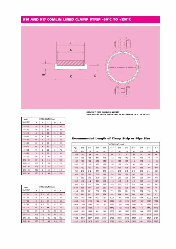
COMLIN ISOLATION PRODUCTS The primary functions of the product groups shown in this section are: The reduction or elimination of noise and fatigue due to vibration of pipework against the supporting structure. The prevention of galvanic corrosion due to the contact of dissimilar metals in the presence of an electrolyte. The prevention of wear and/or crushing of composite, thin-wall or non-ferrous pipework. The materials we offer have been selected to provide optimum performance characteristics over a wide range of applications; our HTFR grade is a flame-retardant material suitable for occasional operation at 350°C. Our low-friction grades, whilst providing very low resistance to sliding pipework, still retain the inherent flexibility of the backing material with no limitation as to how small the pipe can be. We offer two standard product forms: one for applications using pipe clamps where the Comlin is inserted between the clamp and pipe, this is known as ‘clamp strip’. The second is for U-bolt applications where the U-bolt is sheathed with Comlin and provided with a seating strip for protection to the underside of the pipe. Comlin is a family of elastomeric materials developed over a number of years to meet the arduous and very specific requirements of the process pipework engineer.
Transcript
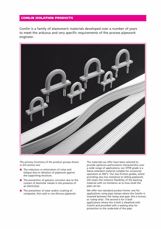
COMLIN ISOLATION PRODUCTS
The primary functions of the product groups shownin this section are:
The reduction or elimination of noise andfatigue due to vibration of pipework againstthe supporting structure.
The prevention of galvanic corrosion due to thecontact of dissimilar metals in the presence ofan electrolyte.
The prevention of wear and/or crushing ofcomposite, thin-wall or non-ferrous pipework.
The materials we offer have been selected toprovide optimum performance characteristics overa wide range of applications; our HTFR grade is aflame-retardant material suitable for occasionaloperation at 350°C. Our low-friction grades, whilstproviding very low resistance to sliding pipework,still retain the inherent flexibility of the backingmaterial with no limitation as to how small thepipe can be.
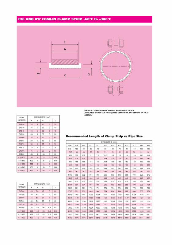
We offer two standard product forms: one forapplications using pipe clamps where the Comlin isinserted between the clamp and pipe, this is knownas ‘clamp strip’. The second is for U-boltapplications where the U-bolt is sheathed withComlin and provided with a seating strip forprotection to the underside of the pipe.
Comlin is a family of elastomeric materials developed over a number of years to meet the arduous and very specific requirements of the process pipeworkengineer.
COMLIN SG60Our standard grade of material, a general purposegrade suitable for most applications within thetemperature range of –40 to 100°C. Based onmodified rubbers reinforced via accretion withspecially selected PVC resins, in many instances itsphysical properties exceed those of establishedthermoplastic elastomers. It has exceptionally goodtensile and tear strength combined with goodresistance to ozone, UV and oil.
COMLIN RG45A specially formulated low modulus polymer alloysuitable for applications that require a very soft,flexible support whilst retaining all the advantagesof this type of material.
It has excellent low-temperature performance andis capable of operating within the temperaturerange –60 to 125°C, with the added advantage ofbeing stable in an irradiated environment. It hasvery good compression set characteristics andwithstands ozone/UV attack and weathering.
This material can be supplied in our own uniquelow-friction form incorporating integral ribs ofpolypropylene embedded into the contact face ofthe product. This is achieved without loss ofproperties or reduction of temperature range. Thisgrade is designated Comlin RG45LF.
COMLIN FR80Our special fire-retardant grade of material has aUL94 flame rating of V-0 and an oxygen index ofonly 25%; it has good resistance to ozone/UVattack and has very good flex fatigue. It also hasgood fluid resistance and good performance inpolar chemicals.
Suitable for most applications within thetemperature range of –50 to 150°C, the materialhas excellent compression set properties,weathering resistance and mechanical strength.
Again, this material can be supplied in our low-friction form, and is designated Comlin FR80LF.
COMLIN HTFR65This high temperature material is suitable forapplications within the temperature range of –60 to350°C. Based on silicone technology, it has excellentresistance to fire, very low toxicity and can operatecontinuously at 300°C with minimum loss ofproperties. This material has excellent resistance toozone, UV and weathering, very good compressionset and is generally resistant to oils.
Due to the high temperature range capability ofthis material, it is not possible to provide it withour low-friction facing.
COMPARISON OF COMLINMATERIALS WITH NEOPRENEOur general purpose grade, Comlin SG60,compares better than neoprene in all respectsother than temperature range: both are restrictedto an upper temperature limit of 100°C. However,with respect to ozone, UV resistance, weathering,mechanical strength and long-term compressionset, Comlin SG60 is superior.
Comlin RG45 and Comlin FR80 grades comparefavourably with neoprene with respect toresistance to ozone/UV attack and weathering, butare far superior when considering compression set,operational temperature range and mechanicalstrength.
Comlin HTFR65 performs considerably better in allrespects than neoprene: resistance to ozone, UV,weathering, temperature and fire are all superior.
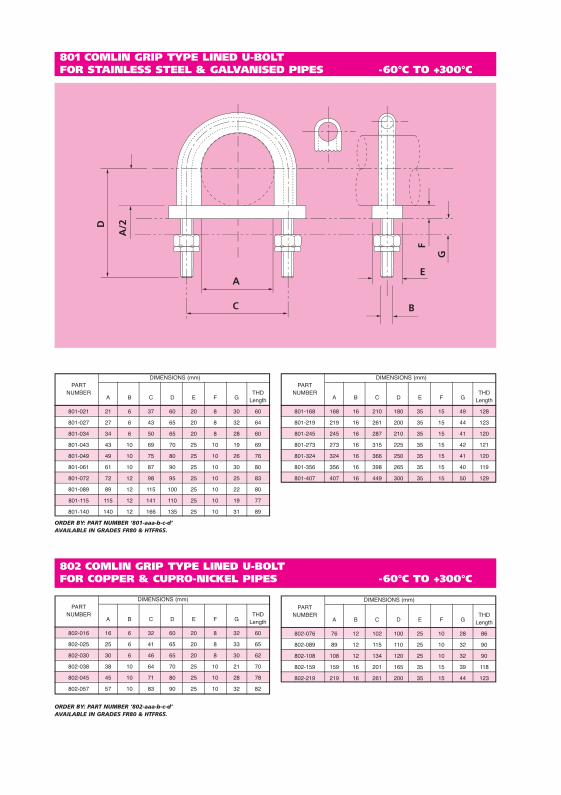
U-BOLT MATERIALThe standard material for Comlin U-Bolts is carbonsteel meeting the requirements of BS4190/DIN601Grade 4.6 with nuts to BS4190/DIN555 Grade 4.
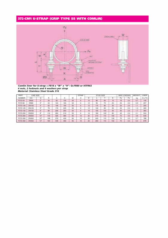
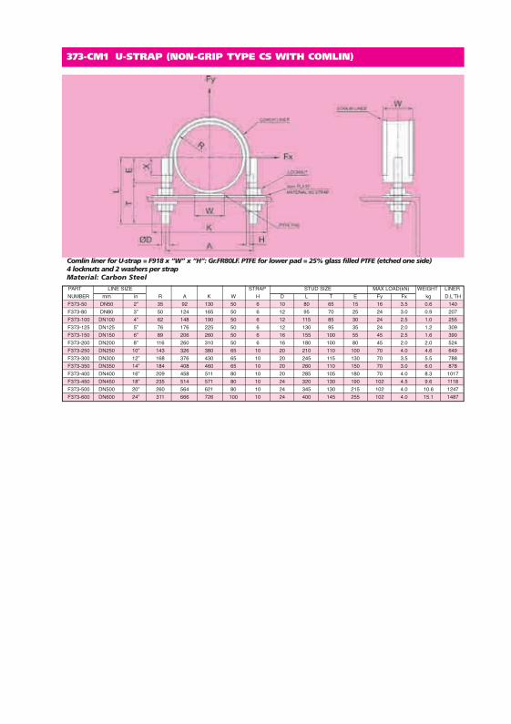
Comlin liner for U-strap = F918 x “W” x “H”: Gr.FR80LF. PTFE for lower pad = 25% glass filled PTFE (etched one side)4 locknuts and 2 washers per strapMaterial: Carbon Steel
Comlin liner for U-strap = F918 x “W” x “H”: Gr.FR80LF. PTFE for lower pad = 25% glass filled PTFE (etched one side)4 locknuts and 2 washers per strapMaterial: Stainless Steel Grade 316
TWO BOLT PIPE CLAMP WITH COMLIN MAX. TEMPERATURE 300ºC
C
E
D
B
ØA
Order by Part Number, Comlin Type and Comlin Grade e.g. PC2-CM2-100-2/817/FR80Material: Carbon Steel and Comlin. Also available in Stainless Steel.Pipe Clamps with other Load Capacities are also available.* Do not exceed the Maximum Temperature for the Grade of Comlin used.
*LOADPART NUMBER FOR PART NUMBER FOR PIPE O/D A B C D E WEIGHT CAPACITYCOMLIN TYPE COMLIN TYPE AT 300°C816, 916, 818 & 918 817 &917 mm in mm mm mm in mm mm kgf kgf
THREE BOLT PIPE CLAMP WITH COMLIN MAX. TEMPERATURE 300ºC
C
D
B
ØA
E
Order by Part Number, Comlin Type and Comlin Grade e.g. PC3-CM2-100-2/817/FR80Material: Carbon Steel and Comlin. Also available in Stainless Steel.Pipe Clamps with other Load Capacities are also available.* Do not exceed the Maximum Temperature for the Grade of Comlin used.
*LOADPART NUMBER FOR PART NUMBER FOR PIPE O/D A B C D E WEIGHT CAPACITYCOMLIN TYPE COMLIN TYPE AT 300°C816, 916, 818 & 918 817 &917 mm in mm mm mm in mm mm kgf kgf
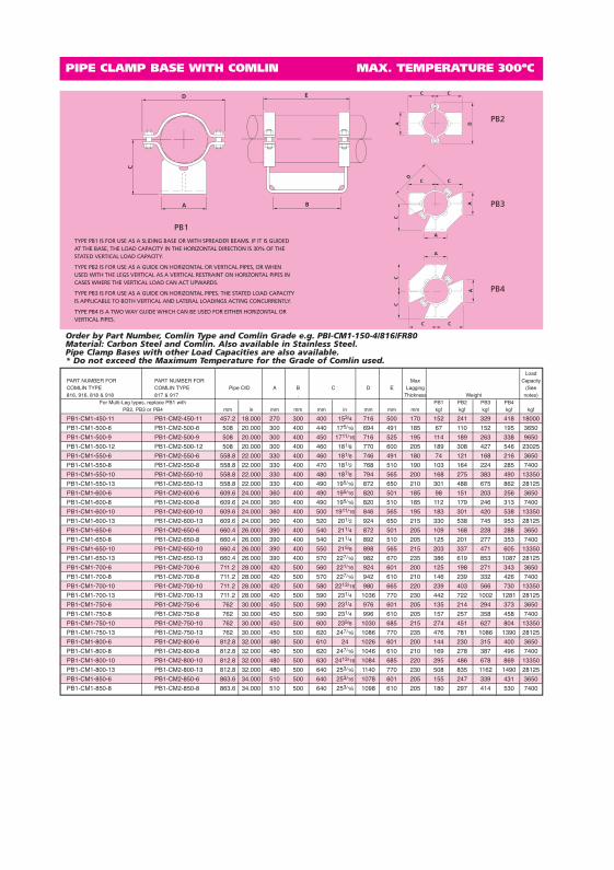
PIPE CLAMP BASE WITH COMLIN MAX. TEMPERATURE 300ºC
D
A
C
E
B
C
A D
C
C C
A
C
A
D
A
CC
CC
A
Order by Part Number, Comlin Type and Comlin Grade e.g. PB1-CM1-150-4/816/FR80Material: Carbon Steel and Comlin. Also available in Stainless Steel.Pipe Clamp Bases with other Load Capacities are also available.* Do not exceed the Maximum Temperature for the Grade of Comlin used.
LoadPART NUMBER FOR PART NUMBER FOR Max CapacityCOMLIN TYPE COMLIN TYPE Pipe O/D A B C D E Lagging (See816, 916, 818 & 918 817 & 917 . Thickness Weight notes)
For Multi-Leg types, replace PB1 with PB1 PB2 PB3 PB4PB2, PB3 or PB4 mm in mm mm mm in mm mm mm kgf kgf kgf kgf kgf
TYPE PB1 IS FOR USE AS A SLIDING BASE OR WITH SPREADER BEAMS. IF IT IS GUIDEDAT THE BASE, THE LOAD CAPACITY IN THE HORIZONTAL DIRECTION IS 30% OF THESTATED VERTICAL LOAD CAPACITY.
TYPE PB2 IS FOR USE AS A GUIDE ON HORIZONTAL OR VERTICAL PIPES, OR WHENUSED WITH THE LEGS VERTICAL AS A VERTICAL RESTRAINT ON HORIZONTAL PIPES INCASES WHERE THE VERTICAL LOAD CAN ACT UPWARDS.
TYPE PB3 IS FOR USE AS A GUIDE ON HORIZONTAL PIPES. THE STATED LOAD CAPACITYIS APPLICABLE TO BOTH VERTICAL AND LATERAL LOADINGS ACTING CONCURRENTLY.
TYPE PB4 IS A TWO WAY GUIDE WHICH CAN BE USED FOR EITHER HORIZONTAL ORVERTICAL PIPES.
PIPE CLAMP BASE WITH COMLIN MAX. TEMPERATURE 300ºC
D
A
C
E
B
C
A D
C
C C
A
C
A
D
A
CC
CC
A
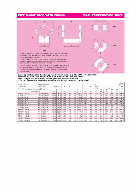
Order by Part Number, Comlin Type and Comlin Grade e.g. PBI-CM1-150-4/816/FR80Material: Carbon Steel and Comlin. Also available in Stainless Steel.Pipe Clamp Bases with other Load Capacities are also available.* Do not exceed the Maximum Temperature for the Grade of Comlin used.
LoadPART NUMBER FOR PART NUMBER FOR Max CapacityCOMLIN TYPE COMLIN TYPE Pipe O/D A B C D E Lagging (See816, 916, 818 & 918 817 & 917 . Thickness Weight notes)
For Multi-Leg types, replace PB1 with PB1 PB2 PB3 PB4PB2, PB3 or PB4 mm in mm mm mm in mm mm mm kgf kgf kgf kgf kgf
TYPE PB1 IS FOR USE AS A SLIDING BASE OR WITH SPREADER BEAMS. IF IT IS GUIDEDAT THE BASE, THE LOAD CAPACITY IN THE HORIZONTAL DIRECTION IS 30% OF THESTATED VERTICAL LOAD CAPACITY.
TYPE PB2 IS FOR USE AS A GUIDE ON HORIZONTAL OR VERTICAL PIPES, OR WHENUSED WITH THE LEGS VERTICAL AS A VERTICAL RESTRAINT ON HORIZONTAL PIPES INCASES WHERE THE VERTICAL LOAD CAN ACT UPWARDS.
TYPE PB3 IS FOR USE AS A GUIDE ON HORIZONTAL PIPES. THE STATED LOAD CAPACITYIS APPLICABLE TO BOTH VERTICAL AND LATERAL LOADINGS ACTING CONCURRENTLY.
TYPE PB4 IS A TWO WAY GUIDE WHICH CAN BE USED FOR EITHER HORIZONTAL ORVERTICAL PIPES.
PIPE CLAMP BASE WITH COMLIN MAX. TEMPERATURE 300ºC
D
A
C
E
B
C
A D
C
C C
A
C
A
D
A
CC
CC
A
Order by Part Number, Comlin Type and Comlin Grade e.g. PBI-CM1-150-4/816/FR80Material: Carbon Steel and Comlin. Also available in Stainless Steel.Pipe Clamp Bases with other Load Capacities are also available.* Do not exceed the Maximum Temperature for the Grade of Comlin used.
LoadPART NUMBER FOR PART NUMBER FOR Max CapacityCOMLIN TYPE COMLIN TYPE Pipe O/D A B C D E Lagging (See816, 916, 818 & 918 817 & 917 . Thickness Weight notes)
For Multi-Leg types, replace PB1 with PB1 PB2 PB3 PB4PB2, PB3 or PB4 mm in mm mm mm in mm mm mm kgf kgf kgf kgf kgf
TYPE PB1 IS FOR USE AS A SLIDING BASE OR WITH SPREADER BEAMS. IF IT IS GUIDEDAT THE BASE, THE LOAD CAPACITY IN THE HORIZONTAL DIRECTION IS 30% OF THESTATED VERTICAL LOAD CAPACITY.
TYPE PB2 IS FOR USE AS A GUIDE ON HORIZONTAL OR VERTICAL PIPES, OR WHENUSED WITH THE LEGS VERTICAL AS A VERTICAL RESTRAINT ON HORIZONTAL PIPES INCASES WHERE THE VERTICAL LOAD CAN ACT UPWARDS.
TYPE PB3 IS FOR USE AS A GUIDE ON HORIZONTAL PIPES. THE STATED LOAD CAPACITYIS APPLICABLE TO BOTH VERTICAL AND LATERAL LOADINGS ACTING CONCURRENTLY.
TYPE PB4 IS A TWO WAY GUIDE WHICH CAN BE USED FOR EITHER HORIZONTAL ORVERTICAL PIPES.