303
AT-S60 Management Software AT-S60 ◆ Command Line User’s Guide AT-8400 SERIES SWITCH VERSION 2.0.0 ® PN 613-50401-00 Rev B

AT-S60Management Software
AT-S60
◆Command Line User’s GuideAT-8400 SERIES SWITCH
VERSION 2.0.0
®
PN 613-50401-00 Rev B
Copyright © 2004 Allied Telesyn, Inc.960 Stewart Drive Suite B, Sunnyvale, CA 94085 USA
All rights reserved. No part of this publication may be reproduced without prior written permission from Allied Telesyn, Inc.
Microsoft is a registered trademark of Microsoft Corporation, Netscape Navigator is a registered trademark of Netscape Communications Corporation. All other product names, company names, logos or other designations mentioned herein are trademarks or registered trademarks of their respective owners.
Allied Telesyn, Inc. reserves the right to make changes in specifications and other information contained in this document without prior written notice. The information provided herein is subject to change without notice. In no event shall Allied Telesyn, Inc. be liable for any incidental, special, indirect, or consequential damages whatsoever, including but not limited to lost profits, arising out of or related to this manual or the information contained herein, even if Allied Telesyn, Inc. has been advised of, known, or should have known, the possibility of such damages.

Table of Contents
Preface ...................................................................................................................................................................................................................... 7How This Guide is Organized ............................................................................................................................................................................. 7
Security Features .......................................................................................................................................................................................... 9Document Conventions ....................................................................................................................................................................................10Where to Find Web-based Guides .................................................................................................................................................................11Contacting Allied Telesyn .................................................................................................................................................................................12
Online Support ............................................................................................................................................................................................ 12Email and Telephone Support ............................................................................................................................................................... 12For Sales or Corporate Information ..................................................................................................................................................... 12
Obtaining Management Software Updates ...............................................................................................................................................13
Chapter 1
Starting a Command Line Management Session ...............................................................................................................................14Starting a Management Session .....................................................................................................................................................................15Command Line Interface Features .................................................................................................................................................................16Command Formatting .......................................................................................................................................................................................17
Specifying Ports .......................................................................................................................................................................................... 17
Chapter 2
Basic Command-Line Commands ..............................................................................................................................................................19CLEAR SCREEN .......................................................................................................................................................................................................20LOGOFF and QUIT ................................................................................................................................................................................................21MENU ........................................................................................................................................................................................................................22SAVE CONFIGURATION ......................................................................................................................................................................................23SET PROMPT ...........................................................................................................................................................................................................24SET SWITCH CONSOLEMODE ...........................................................................................................................................................................25SHOW USER ............................................................................................................................................................................................................26
Chapter 3
Basic Switch Commands .................................................................................................................................................................................27DISABLE DHCPBOOTP ........................................................................................................................................................................................29DISABLE TELNET ...................................................................................................................................................................................................30ENABLE DHCPBOOTP ..........................................................................................................................................................................................31ENABLE TELNET .....................................................................................................................................................................................................32PING ..........................................................................................................................................................................................................................33PURGE IP ..................................................................................................................................................................................................................34RESET ASYN ............................................................................................................................................................................................................35RESET IP ...................................................................................................................................................................................................................36
1

Table of Contents
RESET IP ROUTE .................................................................................................................................................................................................... 37RESET SYSTEM ....................................................................................................................................................................................................... 38RESTART REBOOT ................................................................................................................................................................................................ 39RESTART SWITCH ................................................................................................................................................................................................. 40SET ASYN ................................................................................................................................................................................................................ 41SET IP ........................................................................................................................................................................................................................ 42SET IP ROUTE ......................................................................................................................................................................................................... 44SET PASSWORD MANAGER .............................................................................................................................................................................. 45SET PASSWORD OPERATOR ............................................................................................................................................................................. 46SET SWITCH CONSOLETIMER .......................................................................................................................................................................... 47SET SYSTEM ............................................................................................................................................................................................................ 48SET SYSTEM TEMPTHRESHOLD ...................................................................................................................................................................... 49SHOW ASYN ........................................................................................................................................................................................................... 50SHOW CONFIG ...................................................................................................................................................................................................... 51SHOW DHCPBOOTP ............................................................................................................................................................................................ 52SHOW IP .................................................................................................................................................................................................................. 53SHOW IP ROUTE ................................................................................................................................................................................................... 54SHOW SWITCH ...................................................................................................................................................................................................... 55SHOW SWITCH LINECARD ................................................................................................................................................................................ 56SHOW SYSTEM ...................................................................................................................................................................................................... 57
Chapter 4
Simple Network Time Protocol (SNTP) Commands .......................................................................................................................... 58ADD SNTPSERVER IPADDRESS ........................................................................................................................................................................ 59DELETE SNTPSERVER IPADDRESS .................................................................................................................................................................. 60DISABLE SNTP ....................................................................................................................................................................................................... 61ENABLE SNTP ........................................................................................................................................................................................................ 62RESET SNTP ............................................................................................................................................................................................................ 63SET DATE ................................................................................................................................................................................................................. 64SET SNTP ................................................................................................................................................................................................................. 65SET TIME .................................................................................................................................................................................................................. 66SHOW SNTP ........................................................................................................................................................................................................... 67SHOW TIME ............................................................................................................................................................................................................ 68
Chapter 5
SNMP Community Strings and Trap Commands ............................................................................................................................... 69ADD SNMP COMMUNITY .................................................................................................................................................................................. 70CREATE SNMP COMMUNITY ............................................................................................................................................................................ 72DELETE SNMP COMMUNITY ............................................................................................................................................................................ 75DESTROY SNMP COMMUNITY ........................................................................................................................................................................ 76DISABLE SNMP ...................................................................................................................................................................................................... 77DISABLE SNMP AUTHENTICATETRAP ........................................................................................................................................................... 78DISABLE SNMP COMMUNITY .......................................................................................................................................................................... 79ENABLE SNMP ....................................................................................................................................................................................................... 80ENABLE SNMP AUTHENTICATETRAP ............................................................................................................................................................ 81ENABLE SNMP COMMUNITY ............................................................................................................................................................................ 82SET SNMP COMMUNITY .................................................................................................................................................................................... 83SHOW SNMP .......................................................................................................................................................................................................... 85
Chapter 6
Enhanced Stacking Commands .................................................................................................................................................................. 87ACCESS SWITCH ................................................................................................................................................................................................... 88EXIT ........................................................................................................................................................................................................................... 90SET SWITCH STACKMODE ................................................................................................................................................................................. 91SHOW REMOTELIST ............................................................................................................................................................................................. 92
2

Chapter 7
Port Parameter Commands ..........................................................................................................................................................................93RESET SWITCH PORT ...........................................................................................................................................................................................94SET SWITCH PORT ................................................................................................................................................................................................95SHOW SWITCH PORT ...........................................................................................................................................................................................99
Chapter 8
Port Security Command .............................................................................................................................................................................. 100SET SWITCH PORT SECURITYMODE ............................................................................................................................................................ 101
Chapter 9
Port Trunking Commands .......................................................................................................................................................................... 104ADD SWITCH TRUNK ........................................................................................................................................................................................ 105CREATE SWITCH TRUNK .................................................................................................................................................................................. 106DELETE SWITCH TRUNK .................................................................................................................................................................................. 108DESTROY SWITCH TRUNK ............................................................................................................................................................................... 109SET SWITCH TRUNK .......................................................................................................................................................................................... 110SHOW SWITCH TRUNK .................................................................................................................................................................................... 111
Chapter 10
Port Mirroring Commands ......................................................................................................................................................................... 112ADD SWITCH MIRROR ...................................................................................................................................................................................... 113CREATE SWITCH MIRROR ................................................................................................................................................................................ 114DELETE SWITCH MIRROR ................................................................................................................................................................................ 115DESTROY SWITCH MIRROR ............................................................................................................................................................................ 116DISABLE SWITCH MIRROR .............................................................................................................................................................................. 117ENABLE SWITCH MIRROR ............................................................................................................................................................................... 118SET SWITCH MIRROR ........................................................................................................................................................................................ 119SHOW SWITCH MIRROR .................................................................................................................................................................................. 120
Chapter 11
File System Commands ................................................................................................................................................................................ 121COPY ...................................................................................................................................................................................................................... 122CREATE CONFIG ................................................................................................................................................................................................. 123DELETE FILE ......................................................................................................................................................................................................... 124RENAME ................................................................................................................................................................................................................ 125SET CONFIG ......................................................................................................................................................................................................... 126SHOW FILE ........................................................................................................................................................................................................... 127
Chapter 12
File Download and Upload Commands ............................................................................................................................................... 128LOAD ...................................................................................................................................................................................................................... 129UPLOAD ................................................................................................................................................................................................................ 134
Chapter 13
STP Commands ................................................................................................................................................................................................ 137ACTIVATE STP ..................................................................................................................................................................................................... 138DISABLE STP ........................................................................................................................................................................................................ 139ENABLE STP ......................................................................................................................................................................................................... 140RESET STP ............................................................................................................................................................................................................. 141SET STP .................................................................................................................................................................................................................. 142SET STP PORT ...................................................................................................................................................................................................... 145SHOW STP ............................................................................................................................................................................................................ 147
3
Table of Contents
Chapter 14
RSTP Commands ..............................................................................................................................................................................................148ACTIVATE RSTP ...................................................................................................................................................................................................149DISABLE RSTP ......................................................................................................................................................................................................150ENABLE RSTP .......................................................................................................................................................................................................151RESET RSTP ...........................................................................................................................................................................................................152SET RSTP ................................................................................................................................................................................................................153SET RSTP PORT ....................................................................................................................................................................................................156SHOW RSTP ..........................................................................................................................................................................................................159
Chapter 15
MSTP Commands ............................................................................................................................................................................................161ACTIVATE MSTP ..................................................................................................................................................................................................163ADD MSTP ............................................................................................................................................................................................................164CREATE MSTP ......................................................................................................................................................................................................165DELETE MSTP ......................................................................................................................................................................................................166DESTROY MSTP MSTI ........................................................................................................................................................................................167DISABLE MSTP ....................................................................................................................................................................................................168ENABLE MSTP ......................................................................................................................................................................................................169RESET MSTP .........................................................................................................................................................................................................170SET MSTP ..............................................................................................................................................................................................................171SET MSTP CIST .....................................................................................................................................................................................................174SET MSTP MSTI ...................................................................................................................................................................................................175SET MSTP MSTIVLANASSOC ..........................................................................................................................................................................177SET MSTP PORT ..................................................................................................................................................................................................178SHOW MSTP .........................................................................................................................................................................................................181
Chapter 16
VLANs and Multiple VLAN Commands .................................................................................................................................................183ADD VLAN ............................................................................................................................................................................................................184CREATE VLAN ......................................................................................................................................................................................................187DELETE VLAN .......................................................................................................................................................................................................191DESTROY VLAN ...................................................................................................................................................................................................194RESET VLAN .........................................................................................................................................................................................................195SET SWITCH MANAGEMENTVLAN ...............................................................................................................................................................196SET SWITCH SWITCHMODE ............................................................................................................................................................................197SET VLANMODE ..................................................................................................................................................................................................198SHOW VLAN .........................................................................................................................................................................................................200
Chapter 17
GARP VLAN Registration Protocol Commands .................................................................................................................................201DISABLE GARP ....................................................................................................................................................................................................202ENABLE GARP ......................................................................................................................................................................................................203RESET GARP .........................................................................................................................................................................................................204SET GARP PORT ..................................................................................................................................................................................................205SET GARP TIMER .................................................................................................................................................................................................207SHOW GARP .........................................................................................................................................................................................................209SHOW GARP COUNTER ....................................................................................................................................................................................210SHOW GARP DATABASE ..................................................................................................................................................................................212SHOW GARP GIP .................................................................................................................................................................................................213SHOW GARP MACHINE ....................................................................................................................................................................................214
Chapter 18
MAC Address Table Commands ...............................................................................................................................................................215ADD SWITCH FDB ..............................................................................................................................................................................................216DELETE SWITCH FDB ........................................................................................................................................................................................218
4

SET SWITCH AGINGTIMER .............................................................................................................................................................................. 219SHOW SWITCH FDB .......................................................................................................................................................................................... 220
Chapter 19
IGMP Snooping Commands ....................................................................................................................................................................... 222SET IP IGMP .......................................................................................................................................................................................................... 223SHOW IP IGMP .................................................................................................................................................................................................... 225
Chapter 20
Statistics Commands ..................................................................................................................................................................................... 226RESET SWITCH COUNTER ............................................................................................................................................................................... 227RESET SWITCH LINECARD COUNTER .......................................................................................................................................................... 228RESET SWITCH PORT COUNTER ................................................................................................................................................................... 229SHOW SWITCH COUNTER ............................................................................................................................................................................... 230SHOW SWITCH LINECARD COUNTER ......................................................................................................................................................... 231SHOW SWITCH PORT COUNTER ................................................................................................................................................................... 232
Chapter 21
Web Server Commands ............................................................................................................................................................................... 233DISABLE HTTP SERVER ..................................................................................................................................................................................... 234ENABLE HTTP SERVER ...................................................................................................................................................................................... 235RESET HTTP SERVER .......................................................................................................................................................................................... 236SET HTTP SERVER ............................................................................................................................................................................................... 237
Creating a Self-Signed Certificate ...................................................................................................................................................... 238Creating a CA Certificate ....................................................................................................................................................................... 239
SHOW HTTP SERVER ......................................................................................................................................................................................... 241
Chapter 22
Encryption Commands ................................................................................................................................................................................. 242CREATE ENCO KEY ............................................................................................................................................................................................. 243DESTROY ENCO KEY ......................................................................................................................................................................................... 246SET ENCO KEY ..................................................................................................................................................................................................... 247SHOW ENCO KEY ............................................................................................................................................................................................... 248
Chapter 23
Public Key Infrastructure (PKI) Commands ........................................................................................................................................ 249ADD PKI CERTIFICATE ...................................................................................................................................................................................... 250CREATE PKI CERTIFICATE ................................................................................................................................................................................ 252CREATE PKI ENROLLMENTREQUEST ........................................................................................................................................................... 254DELETE PKI CERTIFICATE ................................................................................................................................................................................. 256PURGE PKI ............................................................................................................................................................................................................ 257SET PKI CERTIFICATE ........................................................................................................................................................................................ 258SET PKI CERTSTORELIMIT ................................................................................................................................................................................ 260SET SYSTEM DISTINGUISHEDNAME ............................................................................................................................................................ 261SHOW PKI ............................................................................................................................................................................................................. 262SHOW PKI CERTIFICATE ................................................................................................................................................................................... 263
Chapter 24
Secure Sockets Layer (SSL) Commands ............................................................................................................................................... 264SET SSL .................................................................................................................................................................................................................. 265SHOW SSL ............................................................................................................................................................................................................ 266
Chapter 25
Secure Shell (SSH) Commands ................................................................................................................................................................. 267DISABLE SSH SERVER ....................................................................................................................................................................................... 268ENABLE SSH SERVER ......................................................................................................................................................................................... 269
5

Table of Contents
SET SSH SERVER ..................................................................................................................................................................................................270Creating a Secure Shell Server ............................................................................................................................................................ 271
SHOW SSH ............................................................................................................................................................................................................273
Chapter 26
802.1x Port-Based Access Control Commands .................................................................................................................................274DISABLE PORTACCESS .....................................................................................................................................................................................275ENABLE PORTACCESS ......................................................................................................................................................................................276SET PORTACCESS ...............................................................................................................................................................................................277SET PORTACCESS PORT AUTHENTICATOR ...............................................................................................................................................278SET PORTACCESS PORT ROLE .......................................................................................................................................................................280SET PORTACCESS PORT SUPPLICANT .........................................................................................................................................................281SHOW PORTACCESS .........................................................................................................................................................................................283
Chapter 27
TACACS+ and RADIUS Commands .........................................................................................................................................................284ADD RADIUSSERVER .........................................................................................................................................................................................285ADD TACACSSERVER ........................................................................................................................................................................................286DELETE RADIUSSERVER ...................................................................................................................................................................................287DELETE TACACSSERVER ..................................................................................................................................................................................288DISABLE AUTHENTICATION ...........................................................................................................................................................................289ENABLE AUTHENTICATION ............................................................................................................................................................................290RESET AUTHENTICATION ................................................................................................................................................................................291SET AUTHENTICATION .....................................................................................................................................................................................292SHOW AUTHENTICATION ...............................................................................................................................................................................294
Index .......................................................................................................................................................................................................................295
6

Preface
This guide contains information about the AT-S60 command line interface. The commands for both the AT-S60 version 2.0.0 NE and 2.0.0 software are included in this manual.
This chapter discusses the following topics:
❑ How This Guide is Organized on page 7
❑ Document Conventions on page 10
❑ Where to Find Web-based Guides on page 11
❑ Contacting Allied Telesyn on page 12
❑ Obtaining Management Software Updates on page 13
How This Guide is Organized
This section describes the organization of the chapters and provides information about the security features covered in this manual.
The commands are grouped by topic into the following chapters:
❑ Chapter 1: Starting a Command Line Management Session
❑ Chapter 2: Basic Command-Line Commands
❑ Chapter 3: Basic Switch Commands
❑ Chapter 4: Simple Network Time Protocol (SNTP) Commands
❑ Chapter 5: SNMP Community Strings and Trap Commands
❑ Chapter 6: Enhanced Stacking Commands
7

Preface
❑ Chapter 7: Port Parameter Commands
❑ Chapter 8: Port Security Command
❑ Chapter 9: Port Trunking Commands
❑ Chapter 10: Port Mirroring Commands
❑ Chapter 11: File System Commands
❑ Chapter 12: File Download and Upload Commands
❑ Chapter 13: STP Commands
❑ Chapter 14: RSTP Commands
❑ Chapter 15: MSTP Commands
❑ Chapter 16: VLANs and Multiple VLAN Commands
❑ Chapter 17: GARP VLAN Registration Protocol Commands
❑ Chapter 18: MAC Address Table Commands
❑ Chapter 19: IGMP Snooping Commands
❑ Chapter 20: Statistics Commands
❑ Chapter 21: Web Server Commands
❑ Chapter 22: Encryption Commands
❑ Chapter 23: Public Key Infrastructure (PKI) Commands
❑ Chapter 24: Secure Sockets Layer (SSL) Command
❑ Chapter 25: Secure Shell (SSH) Commands
❑ Chapter 26T: 802.1x Port-based Access Control Commands
❑ Chapter 27: TACACS+ and RADIUS Commands
The first page of each chapter lists the commands that appear in the chapter. Within each chapter, the commands are listed alphabetically.
8

AT-S60 Command Line User’s Guide
SecurityFeatures
As mentioned above, the commands for both the AT-S60 version 2.0.0 NE and 2.0.0 software are included in this manual. There are several chapters that contain security information for the AT-S60 version 2.0.0 software. They are:
❑ Chapter 21: Web Server Commands
❑ Chapter 22: Encryption Commands
❑ Chapter 23: Public Key Infrastructure (PKI) Commands
❑ Chapter 24: Secure Sockets Layer (SSL) Command
❑ Chapter 25: Secure Shell (SSH) Commands
❑ Chapter 26: 802.1x Port-based Access Control Commands
❑ Chapter 27: TACACS+ and RADIUS Commands
The chapters listed above describe the advanced security and authentication features. The Web Server Chapter contains features that appear in both versions of the software as well as features that only appear in the AT-S60 version 2.0.0 software. The Encryption Services, Public Key Infrastructure (PKI), Secure Socket Layer (SSL), and Secure Shell (SSH) features only appear in the AT-S60 version 2.0.0 software. The authentication features, 802.1x Port Based Access Control as well as TACACS+ and RADIUS protocols, appear in both the AT-S60 version 2.0.0 NE and 2.0.0 software.
CautionThe software described in this documentation contains certain cryptographic functionality and its export is restricted by U.S. law. As of this writing, it has been submitted for review as a “retail encryption item” in accordance with the Export Administration Regulations, 15 C.F.R. Part 730-772, promulgated by the U.S. Department of Commerce, and conditionally may be exported in accordance with the pertinent terms of License Exception ENC (described in 15 C.F.R. Part 740.17). In no case may it be exported to Cuba, Iran, Iraq, Libya, North Korea, Sudan, or Syria. If you wish to transfer this software outside the United States or Canada, please contact your local Allied Telesyn sales representative for current information on this product’s export status.
9

Preface
Document Conventions
This document uses the following conventions:
NoteNotes provide additional information.
WarningWarnings inform you that performing or omitting a specific action may result in bodily injury.
CautionCautions inform you that performing or omitting a specific action may result in equipment damage or loss of data.
10

AT-S60 Command Line User’s Guide
Where to Find Web-based Guides
The installation and user guides for all Allied Telesyn products are available in Portable Document Format (PDF) from on our web site at www.alliedtelesyn.com. You can view the documents on-line or download them onto a local workstation or server.
11

Preface
Contacting Allied Telesyn
This section provides Allied Telesyn contact information for technical support as well as sales or corporate information.
Online Support You can request technical support online by accessing the Allied Telesyn Knowledge Base from the following web site: kb.alliedtelesyn.com. You can use the Knowledge Base to submit questions to our technical support staff and review answers to previously asked questions.
Email andTelephone
Support
For Technical Support via email or telephone, refer to the Support & Services section of the Allied Telesyn web site: www.alliedtelesyn.com.
For Sales orCorporate
Information
You can contact Allied Telesyn for sales or corporate information at our web site: www.alliedtelesyn.com. To find the contact information for your country, select Contact Us then Worldwide Contacts.
12

AT-S60 Command Line User’s Guide
Obtaining Management Software Updates
New releases of management software for our managed products can be downloaded from either of the following Internet sites:
• the Allied Telesyn web site: http://www.alliedtelesyn.com • the Allied Telesyn FTP server: ftp://ftp.alliedtelesyn.com
To use the FTP server, go to the above web site. Then login to the FTP server by entering “anonymous” for the user name and your email address for the password.
13

Chapter 1
Starting a Command Line Management Session
This chapter contains the following topics:
❑ Starting a Management Session on page 15
❑ Command Line Interface Features on page 16
❑ Command Formatting on page 17
14
AT-S60 Command Line User’s Guide
Starting a Management Session
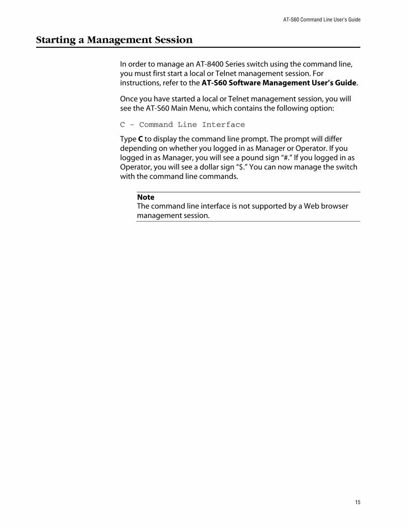
In order to manage an AT-8400 Series switch using the command line, you must first start a local or Telnet management session. For instructions, refer to the AT-S60 Software Management User’s Guide.
Once you have started a local or Telnet management session, you will see the AT-S60 Main Menu, which contains the following option:
C - Command Line Interface
Type C to display the command line prompt. The prompt will differ depending on whether you logged in as Manager or Operator. If you logged in as Manager, you will see a pound sign “#.” If you logged in as Operator, you will see a dollar sign “$.” You can now manage the switch with the command line commands.
NoteThe command line interface is not supported by a Web browser management session.
15

Chapter 1: Starting a Command Line Management Session
Command Line Interface Features
The following features are supported in the command line interface:
❑ Command history - Use the up and down arrow keys.
❑ Context-specific help - Press the question mark key at any time to see a list of legal next parameters.
❑ Keyword abbreviations - Any keyword can be recognized by typing an unambiguous prefix (for example, “sh” for “show”).
16

AT-S60 Command Line User’s Guide
Command Formatting
The following formatting conventions are used in this manual:
❑ screen text font - This font illustrates the format of a command and command examples.
❑ screen text font - Italicized screen text indicates a variable for you to enter.
❑ [ ] - Brackets indicate optional parameters.
❑ | - bar symbol separates parameter options for you to choose from.
Specifying Ports Many commands in this manual require you to specify the port where you want the command performed. Port numbers are entered in the following format:
slot.port
Slot is the number of the slot in the AT-8400 Series switch containing the line card. The AT-8400 Chassis has 12 slots for line cards. Port is the port number on the line card. For instance, to indicate Port 4 on a line card in Slot 8, enter:
8.4
For example, to view the parameter settings for the above port, enter:
show switch port=8.4
Some commands allow you to specify more then one port at a time. Ports on the same line card can be listed individually, as a range, or both. The following example displays the port parameters for Ports 1, 3, and 5 through 8 on the line card in Slot 3:
show switch port=3.1,3,5-8
Some commands can be performed on ports on different line cards simultaneously. This example displays the port parameters for Ports 1 and 4 on the line card in Slot 4 and Ports 6 to 8 on the line card in Slot 11:
show switch port=4.1,4,11.6-8
17

Chapter 1: Starting a Command Line Management Session
NoteThe AT-8413 G/BT line card comes with one 10/100/1000Base-T twisted pair port and one GBIC expansion slot. Only one port is active on the line card at a time. The port number for the active port is always 1. You cannot display or modify the settings of the inactive port.
18

Chapter 2
Basic Command-Line Commands
This chapter contains the following commands:
❑ CLEAR SCREEN on page 20
❑ LOGOFF and QUIT on page 21
❑ MENU on page 22
❑ SAVE CONFIGURATION on page 23
❑ SET PROMPT on page 24
❑ SET SWITCH CONSOLEMODE on page 25
❑ SHOW USER on page 26
NoteRemember to save your changes with the SAVE CONFIGURATION command.
NoteRefer to the AT-S60 Management Software User’s Guide for background information on basic switch parameters.
19

Chapter 2: Basic Command Line Commands
CLEAR SCREEN
Syntax
clear screen
Parameters
None.
Description
This command clears the screen.
Example
The following command clears the screen:
clear screen
20

AT-S60 Command Line User’s Guide
LOGOFF and QUIT
Syntax
logoff
quit
Parameters
None.
Description
Both commands perform the same function: they end a management session. If you are managing a slave switch, the commands return you to the master switch from which you started the management session.
Example
The following command ends a management session:
logoff
21
Chapter 2: Basic Command Line Commands
MENU
Syntax
menu
Parameters
None.
Description
This command displays the AT-S60 Main Menu. For instructions on how to use the management menus, refer to the AT-S60 Management Software User’s Guide.
Example
The following command displays the AT-S60 Main Menu:
menu
22

AT-S60 Command Line User’s Guide
SAVE CONFIGURATION
Syntax
save configuration
Parameters
None.
Description
This command saves your changes to the switch’s flash memory for permanent storage.
Whenever you make a change to an operating parameter of the switch, such as enter a new IP address or create a new VLAN, the change is stored in temporary memory. It is lost the next time you reset the switch or power cycle the unit.
To permanently save your changes, you must use this command. The changes are saved to flash memory and retained even when the switch is reset or powered off.
Example
The following command saves your configuration changes:
save configuration
23
Chapter 2: Basic Command Line Commands
SET PROMPT
Syntax
set prompt=”prompt”
Parameter
prompt Specifies the command line prompt. The prompt can be from one to seven alphanumeric characters. Spaces and special characters are allowed. The prompt must be enclosed in quotes.
Description
This command changes the command prompt. Assigning each switch a different command prompt can make it easy for you to identify the switches in your network.
Example
The following command changes the command prompt to “Sales Switch”:
set prompt=”Sales Switch”
24

AT-S60 Command Line User’s Guide
SET SWITCH CONSOLEMODE
Syntax
set switch consolemode=menu|cli
Parameter
consolemode Specifies the mode you want management sessions to start in. Options are:
menu Specifies the AT-S60 Main Menu. This is the default.
cli Specifies the command line prompt.
Description
You use this command to specify whether you want your management sessions to start by displaying the command line interface or the AT-S60 Main Menu. The default is the Main Menu.
Example
The following command configures the management software to display the command line prompt whenever you start a management session:
set switch consolemode=cli
25

Chapter 2: Basic Command Line Commands
SHOW USER
Syntax
show user
Parameter
None.
Description
Displays the user account you used to log on to the switch. The user account is Manager or Operator.
Example
show user
26

Chapter 3
Basic Switch Commands
This chapter contains the following commands:
❑ DISABLE DHCPBOOTP on page 29
❑ DISABLE TELNET on page 30
❑ ENABLE DHCPBOOTP on page 31
❑ ENABLE TELNET on page 32
❑ PING on page 33
❑ PURGE IP on page 34
❑ RESET ASYN on page 35
❑ RESET IP on page 36
❑ RESET IP ROUTE on page 37
❑ RESET SYSTEM on page 38
❑ RESTART REBOOT on page 39
❑ RESTART SWITCH on page 40
❑ SET ASYN on page 41
❑ SET IP on page 42
❑ SET IP ROUTE on page 44
❑ SET PASSWORD MANAGER on page 45
❑ SET PASSWORD OPERATOR on page 46
❑ SET SWITCH CONSOLETIMER on page 47
27

Chapter 3: Basic Switch Commands
❑ SET SYSTEM on page 48
❑ SET SYSTEM TEMPTHRESHOLD on page 49
❑ SHOW ASYN on page 50
❑ SHOW CONFIG on page 51
❑ SHOW DHCPBOOTP on page 52
❑ SHOW IP on page 53
❑ SHOW IP ROUTE on page 54
❑ SHOW SWITCH on page 55
❑ SHOW SWITCH LINECARD on page 56
❑ SHOW SYSTEM on page 57
NoteRemember to save your changes with the SAVE CONFIGURATION command.
NoteRefer to the AT-S60 Management Software User’s Guide for background information on basic switch parameters.
28

AT-S60 Command Line User’s Guide
DISABLE DHCPBOOTP
Syntax
disable dhcpbootp
Parameters
None.
Description
This command deactivates the DHCP and BOOTP client software on the switch.
Example
The following command deactivates DHCP and BOOTP:
disable dhcpbootp
29

Chapter 3: Basic Switch Commands
DISABLE TELNET
Syntax
disable telnet
Parameters
None
Description
This command disables Telnet access to the switch.
CautionBefore you enable the Secure Shell (SSH) feature, disable Telnet access to the switch. If you do not disable Telnet while SSH is enabled, the security provided by SSH is rendered ineffective.
Example
disable telnet
30

AT-S60 Command Line User’s Guide
ENABLE DHCPBOOTP
Syntax
enable dhcpbootp
Parameters
None.
Description
This command activates the DHCP and BOOTP client software on the switch. When activated, the switch obtains its IP configuration from a DHCP or BOOTP server on your network, whenever the unit is power cycled or reset. The client software makes continuous requests for its IP configuration until a DHCP or BOOTP server responds.
If you assigned the switch an IP address manually, the address is discarded when DHCP and BOOTP are activated.
The default setting for DHCP and BOOTP is disabled.
NoteYou cannot manually assign an IP address or subnet mask to a switch once the DHCP and BOOTP client software have been activated. To disable DHCP and BOOTP, refer to the DISABLE DHCPBOOTP command.
Example
The following command activates the DHCP and BOOTP client software on the switch:
enable dhcpbootp
31

Chapter 3: Basic Switch Commands
ENABLE TELNET
Syntax
enable telnet
Parameters
None.
Description
This command enables Telnet access to the switch.
Example
The following command enables Telnet access to the switch:
enable telnet
32

AT-S60 Command Line User’s Guide
PING
Syntax
ping ipaddress
Parameter
ipaddress Specifies the IP address of an end node you want the switch to ping.
Description
This command instructs the switch to ping an end node. You can use this command to determine whether a valid link exists between the switch and another device.
Example
The following command pings an end node with the IP address of 149.245.22.22
ping 149.245.22.22
The results of the ping are displayed on the screen.
33

Chapter 3: Basic Switch Commands
PURGE IP
Syntax
purge ip [ipaddress] [netmask] [route]
Parameters
ipaddress Returns the switch’s IP address to the default setting of 0.0.0.0.
netmask Returns the subnet mask to the default setting of 0.0.0.0.
route Returns the gateway address to the default setting of 0.0.0.0.
Description
This command returns the switch’s IP address, subnet mask, and default gateway address to the default settings. This command is similar in function to the RESET IP command. Where they differ is that this command allows you to specify which parameter to reset, while the RESET IP command automatically resets all three parameters.
Examples
The following command returns the IP address and subnet mask to the default values:
purge ip ipaddress netmask
The following command resets just the gateway address to its default value:
purge ip ipaddress route
34

AT-S60 Command Line User’s Guide
RESET ASYN
Syntax
reset asyn
Parameter
None.
Description
This command resets the speed of the serial port on the AT-8401 management fabric card to the default value of 9600 bps.
NoteIf you are managing the switch locally, changing the baud rate of the serial port ends your management session.
For instructions on how to set the serial port’s speed, refer to SET ASYN on page 41.
Example
The following command sets the speed of the serial port to 9600 bps:
reset asyn
35

Chapter 3: Basic Switch Commands
RESET IP
Syntax
reset ip interface=1
Parameter
interface Specifies the interface number. This value is always 1.
Description
This command returns the IP address, subnet mask, and gateway address to their default values, which are:
❑ IP address: 0.0.0.0
❑ Subnet mask: 0.0.0.0
❑ Default gateway address: 0.0.0.0
To return one of the above parameters to its default value, refer to PURGE IP on page 34.
Example
The following command returns the switch’s IP address, subnet mask, and gateway address to their default values:
reset ip interface=1
36
AT-S60 Command Line User’s Guide
RESET IP ROUTE
Syntax
reset ip route
Parameter
None.
Description
This command returns the default gateway address to its default value of 0.0.0.0. (You can use the PURGE IP on page 34 to perform the same function.)
Example
The following command returns the default gateway address to 0.0.0.0:
reset ip route
37
Chapter 3: Basic Switch Commands
RESET SYSTEM
Syntax
reset system [name] [contact] [location]
Parameters
name Deletes the name of the switch.
contact Deletes the name of the network administrator responsible for managing the unit.
location Deletes the location of the switch.
Description
This command deletes the switch’s name, the name of the network administrator responsible for managing the unit, and the location of the unit.
NoteTo set the name, contact, or location of a switch, refer to SET SYSTEM on page 48.
Examples
The following command deletes the switch’s name, the name of the network administrator, and the location of the unit:
reset system
The following command deletes the location:
reset system location
38

AT-S60 Command Line User’s Guide
RESTART REBOOT
Syntax
restart reboot
Parameters
None.
Description
This command returns the switch’s operating parameters to the default settings. For a list of the default settings, see Appendix A: AT-S60 Default Settings of the AT-S60 Management Software User’s Guide.
Example
The following command returns the switch’s operating parameters to the default settings:
restart reboot
39

Chapter 3: Basic Switch Commands
RESTART SWITCH
Syntax
restart switch
Parameters
None.
Description
This command resets the switch. The system reset takes approximately 20 to 30 seconds to complete. The unit does not forward traffic during the time required to run its internal diagnostics and reload the operating software.
Your local or remote management session with the switch ends when you reset the unit You must reestablish the session to continue managing the switch.
CautionBe sure to use the SAVE CONFIGURATION command to save your changes before resetting the switch. Any unsaved changes are discarded.
Example
The following command resets the switch:
restart switch
40

AT-S60 Command Line User’s Guide
SET ASYN
Syntax
set asyn speed=1200|2400|4800|9600|19200|38400|57600|115200
Parameter
speed Sets the speed of the serial port on the AT-8401 management card. The default is 9600 bps.
Description
This command sets the baud rate of the serial port on the AT-8401 management card. The serial port is used for local management of the switch.
NoteChanging the baud rate of the serial port ends your management session if you are managing the switch locally. To reestablish a local management session, you must change the speed of the terminal (or the terminal emulator program) to match the speed of the serial port.
Example
This example sets the baud rate to 115,200 bps:
set asyn speed=115200
41

Chapter 3: Basic Switch Commands
SET IP
Syntax
set ip interface=1 ipaddress=ipaddress|DHCP netmask=subnetmask
Parameters
interface Specifies the interface number. This value is always 1.
ipaddress Specifies an IP address for the switch or activates the DHCP and BOOTP client software. For background information on when to assign a switch an IP address, refer to the AT-S60 Management Software User’s Guide.
netmask Specifies the subnet mask for the switch. You must specify a subnet mask if you manually assigned the switch an IP address.
Description
This command configures the following switch parameters:
❑ IP address
❑ Subnet mask
This command can also activate the DHCP and BOOTP client software on the switch. Activating DHCP and BOOTP with this command is equivalent to using ENABLE DHCPBOOTP on page 31.
To display the current IP address and subnet mask, refer to SHOW IP on page 53. To return the IP address and subnet mask to their default values, refer to PURGE IP on page 34. To deactivate DHCP and BOOTP client software on the switch, refer to DISABLE DHCPBOOTP on page 29.
NoteYou cannot assign an IP address to the switch if DHCP and BOOTP are activated.
42

AT-S60 Command Line User’s Guide
Examples
The following command sets the switch’s IP address to 140.35.22.22 and the subnet mask to 255.255.255.0:
set ip interface=1 ipaddress=140.35.22.22 netmask=255.255.255.0
The following command sets the subnet mask:
set ip interface=1 netmask=255.255.255.252
The following command activates the DHCP and BOOTP client software:
set ip interface=1 ipaddress=dhcp
To deactivate DHCP and BOOTP client software on the switch, refer to DISABLE DHCPBOOTP on page 29.
43

Chapter 3: Basic Switch Commands
SET IP ROUTE
Syntax
set ip route ipaddress=ipaddress
Parameter
ipaddress Specifies the IP address of the default gateway for the switch.
Description
This command specifies the IP address of the default gateway for the AT-8400 Series switch. This IP address is required if you intend to remotely manage the device from a remote management station that is separated from the unit by a router.
Example
The following command sets the default gateway to 140.35.22.12:
set ip route ipaddress=140.35.22.12
44

AT-S60 Command Line User’s Guide
SET PASSWORD MANAGER
Syntax
set password manager
Parameters
None.
Description
This command sets the manager’s password. The default password is “friend.” The password can be from 1 to 20 alphanumeric characters. Allied Telesyn International recommends avoiding special characters, such as spaces, asterisks or exclamation points, since some web browsers do not accept them in passwords. The password is case sensitive.
Example
The following command changes the manager’s password:
set password manager
Follow the prompts to enter the new password.
45

Chapter 3: Basic Switch Commands
SET PASSWORD OPERATOR
Syntax
set password operator
Parameters
None.
Description
This command sets the operator’s password. The default password is “operator.” The password can be from 1 to 20 alphanumeric characters. Allied Telesyn International recommends avoiding special characters, such as spaces, asterisks or exclamation points, since some web browsers do not accept them in passwords. The password is case sensitive.
Example
The following command changes the operator’s password:
set password operator
Follow the prompts to enter the new password.
46

AT-S60 Command Line User’s Guide
SET SWITCH CONSOLETIMER
Syntax
set switch consoletimer=value
Parameter
consoletimer Specifies the console timer in minutes. The range is 1 to 60 minutes. The default is 10 minutes.
Description
This command sets the console timer, which is used by the management software, to end inactive management sessions. If the AT-S60 software does not detect any activity from a local or remote management station after the time set with the console timer, it automatically ends the management session.
This security feature can prevent unauthorized individuals from using your management station should you step away from your system while configuring a switch. To view the current console timer setting (console startup mode), refer to SHOW SWITCH on page 55.
Example
The following command sets the console timer to 25 minutes:
set switch consoletimer=25
47
Chapter 3: Basic Switch Commands
SET SYSTEM
Syntax
set system [name=”name”] [contact=”contact”] [location=”location”]
Parameters
The parameters are defined below:
name Specifies the name of the switch. The name can be from 1 to 15 alphanumeric characters in length and must be enclosed in quotes (“ “). Spaces are permitted.
contact Specifies the name of the network administrator responsible for managing the switch. This field can be from 1 to 15 alphanumeric characters in length and must be enclosed in quotes (“ “). Spaces are permitted.
location Specifies the location of the switch. The location of a switch is often a building and room number. The location can be from 1 to 15 alphanumeric characters in length and must be enclosed in quotes (“ “). Spaces are permitted.
Description
This command sets a switch’s name, the name of the network administrator responsible for managing the unit, and the location of the unit.
If one of the above parameters already has a value, the new value replaces the existing value. If you want to delete an existing name, contact, or location value without assigning a new value, refer to RESET SYSTEM on page 38.
Examples
The following command sets the system name to Sales, the contact to Jane Smith, and the location to Bldg 3, rm 212:
set system name=”Sales” contact=”Jane Smith” location “Bldg 3, rm 212”
The following command sets the system name to PR Office:
set system name=”PR Office”
48

AT-S60 Command Line User’s Guide
SET SYSTEM TEMPTHRESHOLD
Syntax
set system tempthreshold=temperature
Parameter
The parameter is defined below:
tempthreshold Specifies the maximum operating temperature for the switch. The range is 0° to 90°C. The default is 80°C.
Description
This command sets the switch’s maximum operating temperature. If the switch exceeds the temperature, the AT-S60 management software sends a trap to the management workstations.
Example
The following command sets the switch’s maximum operating temperature to 75°C:
set system tempthreshold=75
49

Chapter 3: Basic Switch Commands
SHOW ASYN
Syntax
show asyn
Parameters
None.
Description
This command displays the following operating parameters of the serial port on the AT-8401 management card:
❑ Baud rate
❑ Parity
❑ Data bits
❑ Stop bits
Of the above values, only the baud rate is adjustable on the serial port. To change it, refer to SET ASYN on page 41.
Example
The following command displays the operating parameters of the serial port:
show asyn
50

AT-S60 Command Line User’s Guide
SHOW CONFIG
Syntax
show config
Parameters
None.
Description
This command displays the following information:
❑ Boot configuration file - This is the configuration file the switch will use the next time it is reset or power cycled.
❑ Current configuration file - This is the configuration file the switch is currently using.
To change the configuration file, refer to SET CONFIG on page 126.
Example
The following command displays configuration file information:
show config
51

Chapter 3: Basic Switch Commands
SHOW DHCPBOOTP
Syntax
show dhcpbootp
Parameters
None.
Description
This command displays the status of the DHCP and BOOTP client software on the switch. The status is either “enabled” or “disabled.” The default setting for DHCP and BOOTP is disabled.
To enable DHCP and BOOTP client software, refer to ENABLE DHCPBOOTP on page 31. To disable the DHCP and BOOTP client software, refer to DISABLE DHCPBOOTP on page 29.
Example
The following command displays the status of the DHCP and BOOTP client software:
show dhcpbootp
52

AT-S60 Command Line User’s Guide
SHOW IP
Syntax
show ip interface=1
Parameters
interface Specifies the switch’s interface number. This value is always 1.
Description
This command displays the current values for the following switch parameters:
❑ IP address
❑ Subnet mask
❑ Default gateway
To set the IP address and subnet mask, refer to SET IP on page 42. To set the default gateway address, refer to SET IP ROUTE on page 44.
Example
The following command displays the IP address, subnet mask, and default gateway of the switch:
show ip interface=1
53

Chapter 3: Basic Switch Commands
SHOW IP ROUTE
Syntax
show ip route
Parameters
None.
Description
This command displays the switch’s default gateway address. You can also display the gateway address using SHOW IP on page 53.
To set the default gateway address, refer to SET IP ROUTE on page 44.
Example
The following command displays the default gateway address of the switch:
show ip route
54
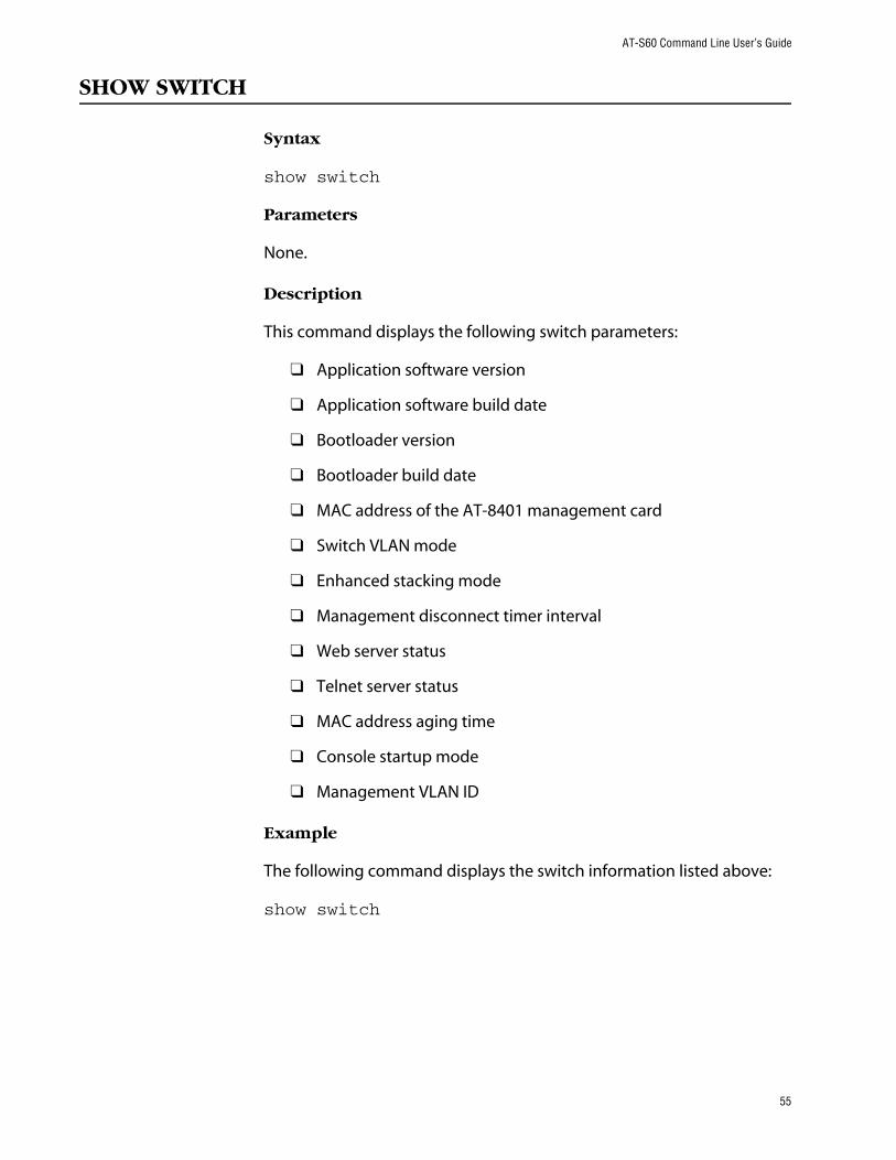
AT-S60 Command Line User’s Guide
SHOW SWITCH
Syntax
show switch
Parameters
None.
Description
This command displays the following switch parameters:
❑ Application software version
❑ Application software build date
❑ Bootloader version
❑ Bootloader build date
❑ MAC address of the AT-8401 management card
❑ Switch VLAN mode
❑ Enhanced stacking mode
❑ Management disconnect timer interval
❑ Web server status
❑ Telnet server status
❑ MAC address aging time
❑ Console startup mode
❑ Management VLAN ID
Example
The following command displays the switch information listed above:
show switch
55

Chapter 3: Basic Switch Commands
SHOW SWITCH LINECARD
Syntax
show switch linecard=slotnumber
Parameter
linecard Specifies the slot number containing the line card whose information you want to view.
Description
This command displays the following line card information:
❑ Serial number
❑ Model name
❑ Operating temperature
Example
The following command displays the above information for the line card in Slot 2:
show switch linecard=2
56

AT-S60 Command Line User’s Guide
SHOW SYSTEM
Syntax
show system
Parameters
None.
Description
This command displays the following information:
❑ Application software version
❑ Application software build date
❑ Bootloader version
❑ Bootloader version build date
❑ Model name
❑ Switch name
❑ Name of the network administrator responsible for managing the unit
❑ Location of the unit
❑ Distinguished name
❑ Temperature threshold (Celsius)
For instructions on how to set the name, contact, and location of the switch, see SET SYSTEM on page 48. For information on setting the distinguished name, refer to SET SYSTEM DISTINGUISHEDNAME on page 261. For instructions on how to set the temperature threshold, refer to SET SYSTEM TEMPTHRESHOLD on page 49.
Example
The following command displays the information about the switch listed above:
show system
57

Chapter 4
Simple Network Time Protocol (SNTP) Commands
This chapter contains the following commands:
❑ ADD SNTPSERVER IPADDRESS on page 59
❑ DELETE SNTPSERVER IPADDRESS on page 60
❑ DISABLE SNTP on page 61
❑ ENABLE SNTP on page 62
❑ RESET SNTP on page 63
❑ SET DATE on page 64
❑ SET SNTP on page 65
❑ SET TIME on page 66
❑ SHOW SNTP on page 67
❑ SHOW TIME on page 68
NoteRemember to save your changes with the SAVE CONFIGURATION command.
NoteRefer to the AT-S60 Management Software User’s Guide for background information on SNTP.
58

AT-S60 Command Line User’s Guide
ADD SNTPSERVER IPADDRESS
Syntax
add sntpserver ipaddress=ip-address
Parameter
ipaddress Specifies the IP address of the SNTP server.
Description
This command specifies the IP address of the SNTP server.
Example
The following command adds an SNTP server IP address:
add sntpserver ipaddress=148.35.16.248
59

Chapter 4: SNTP Commands
DELETE SNTPSERVER IPADDRESS
Syntax
delete sntpserver ipaddress=ip-address
Parameter
ipaddress Specifies the IP address of the SNTP server.
Description
This command deletes the IP address of the SNTP server.
Example
The following command deletes the SNTP server IP address:
delete sntpserver ipaddress=148.35.16.248
60

AT-S60 Command Line User’s Guide
DISABLE SNTP
Syntax
disable sntp
Parameters
None.
Description
This command disables SNTP.
Example
The following command disables SNTP on the switch:
disable sntp
61

Chapter 4: SNTP Commands
ENABLE SNTP
Syntax
enable sntp
Parameters
None.
Description
This command enables SNTP.
Example
The following command enables SNTP:
enable sntp
62

AT-S60 Command Line User’s Guide
RESET SNTP
Syntax
reset sntp
Parameters
None.
Description
This command resets SNTP to its default values.
Example
The following command resets SNTP:
reset sntp
63

Chapter 4: SNTP Commands
SET DATE
Syntax
set date dd-mm-yyyy
Parameter
date Specifies the date for the SNTP server in day/month/year format.
Description
This command sets the date on the SNTP server.
Example
The following command sets the date to November 9, 2003:
set date 9-11-2003
64

AT-S60 Command Line User’s Guide
SET SNTP
Syntax
set sntp[dst=enabled|disabled] [pollinterval=integer] [utcoffset=integer]
Parameters
dst Daylight savings time. By setting this parameter to enabled, you allow the switch to automatically adjust to daylight savings time. By setting this parameter to disabled, you prevent the switch from automatically adjusting to daylight savings time.
pollinterval The time interval between two successive queries to the SNTP server. The range is 60 to 1200 seconds. The default is 600 seconds.
utcoffset The time difference, in hours, between Universal Coordinated Time (UTC) and local time. The range is -12 to +12 hours. The default is 0 hours.
Description
This command enables or disables daylight savings time and sets the polling and UTC offset times.
Example
The following command enables daylight savings time, sets the poll interval to 300 seconds, and sets the UTC offset to -8 hours:
set sntp dst=enabled pollinterval=300 utcoffset=-8
65
Chapter 4: SNTP Commands
SET TIME
Syntax
set time hh:mm:ss
Parameter
time Specifies the hour, minutes, and seconds of the current time in 24-hour format.
Description
This command sets the system time.
Example
The following command sets the time to 4:34:52 pm.
set time 16:34:52
66

AT-S60 Command Line User’s Guide
SHOW SNTP
Syntax
show sntp
Parameters
None.
Description
This command displays the following information:
❑ Status
❑ Server IP address
❑ UTC Offset
❑ Daylight Savings Time (DST) - enabled or disabled
❑ Poll Interval
❑ Last Delta - The last adjustment that was applied to the system time. It is the drift in the system clock between two successive queries to the SNTP server.
Example
The following command displays SNTP information:
show sntp
67

Chapter 4: SNTP Commands
SHOW TIME
Syntax
show time
Parameters
None.
Description
This command shows the current system time.
Example
The following command shows the current system time.
show time
68

Chapter 5
SNMP Community Strings and Trap Commands
This chapter contains the following commands:
❑ ADD SNMP COMMUNITY on page 70
❑ CREATE SNMP COMMUNITY on page 72
❑ DELETE SNMP COMMUNITY on page 75
❑ DESTROY SNMP COMMUNITY on page 76
❑ DISABLE SNMP on page 77
❑ DISABLE SNMP AUTHENTICATETRAP on page 78
❑ DISABLE SNMP COMMUNITY on page 79
❑ ENABLE SNMP on page 80
❑ ENABLE SNMP AUTHENTICATETRAP on page 81
❑ ENABLE SNMP COMMUNITY on page 82
❑ SET SNMP COMMUNITY on page 83
❑ SHOW SNMP on page 85
NoteRemember to save your changes with the SAVE CONFIGURATION command.
NoteRefer to the AT-S60 Management Software User’s Guide for background information about SNMP.
69

Chapter 5: SNMP Community Strings and Trap Commands
ADD SNMP COMMUNITY
Syntax
add snmp community=community [traphost=ipaddress] [manager=ipaddress]
Parameters
community Specifies an existing SNMP community string on the switch.
traphost Specifies the IP address of a trap receiver.
manager Specifies the IP address of a management workstation that has SNMP access to the switch using the community string.
Description
This command adds a trap receiver or a management station to an existing community string.
The TRAPHOST parameter specifies a trap receiver for the SNMP community string. This is the IP address of a device to which traps generated by the switch are sent. A community string can have up to eight IP addresses of trap receivers, but only one IP address can be added at a time with this command.
The MANAGER parameter specifies the management station that is permitted SNMP management access to the switch using the community string. A community string can have up to eight IP addresses of management stations, but only one IP address can be added at a time with this command.
To create a new community string, refer to CREATE SNMP COMMUNITY on page 72. To view the current community strings, refer to SHOW SNMP on page 85.
Examples
The following command permits access by a management station with the IP address of 149.212.11.22 to the switch through the “private” community string:
add snmp community=private manager=149.212.11.22
70

AT-S60 Command Line User’s Guide
The following command adds the IP address of 149.212.10.11 as a trap receiver to the “public” community string:
add snmp community=public traphost=149.212.10.11
71

Chapter 5: SNMP Community Strings and Trap Commands
CREATE SNMP COMMUNITY
Syntax
create snmp community=community [access=read|write] [open=yes|no] [traphost=ipaddress] [manager=ipaddress]
Parameters
community Specifies a new community string. The maximum length of a community string is 15 alphanumeric characters.
access Specifies the access level of the new community string. Options are “read” for read only access and “write” for both read and write access. The default is “read.”
open Specifies the open or closed status of the community string. The options are:
yes The community string is open, meaning that any management workstation can use the string to access the switch.
no The community string is closed, meaning that only those management workstations whose IP addresses are assigned to the string can use it to access the switch. You can assign a management IP address to the string using the MANAGER option in this command. The default setting for a community string is closed.
traphost Specifies the IP address of a trap receiver to receive system traps.
manager Specifies the IP address of a management station that can use the community string to access the switch. This option applies if you specify the status of the community string as closed. A community string can have up to eight IP addresses of management workstations, but only one IP address can be assigned with this option.
72

AT-S60 Command Line User’s Guide
Description
This command creates a new SNMP community string on the switch. The switch comes with two default community strings, “public,” with an access of read only, and “private,” with an access level of read and write. A switch can support up to eight community strings.
The COMMUNITY parameter specifies the new community string. The string can be up to 15 alphanumeric characters.
The ACCESS parameter defines the access level for the new community string. The access level can be either read or read and write. The READ option specifies the read access level and the WRITE option specifies the read and write access level.
The OPEN parameters controls whether the string will have an opened or closed status. If you use the YES option, the string will have an open status. Any management workstation will be able to use the string to access the switch. If you specify NO, which is the default, then the string will have a closed status and only those management workstations whose IP addresses are assigned to the switch will be able to use the string.
The TRAPHOST parameter specifies the IP address of a trap receiver to receive traps from the switch. A community string can have up to eight trap receivers, but only one can be assigned when a community string is created. To add IP addresses of trap receivers to an existing community string, see ADD SNMP COMMUNITY on page 70.
The MANAGER parameter specifies the IP address of a management station that is permitted SNMP access to the switch through the community string. You use this parameter when you give a community string a closed status. A community string with a closed status can only be used by those management workstations whose IP addresses have been assigned to the string.
A community string can have up to eight manager IP addresses, but only one can be assigned when a community string is created. To add IP addresses of management stations to an existing community string, see ADD SNMP COMMUNITY on page 70.
Examples
The following command creates the new community string “serv12” with read access level and an access status of open:
create snmp community=serv12 access=read open=yes
73
Chapter 5: SNMP Community Strings and Trap Commands
The following command creates the new community string “wind11” with read and write access level. To limit the use of the string, it is given an access status of closed and assigned the IP address of a management workstation:
create snmp community=wind11 access=write open=no manager=149.35.24.22
(The OPEN=NO parameter could be omitted from the example since closed status is the default for a new community string.)
This command is identical to the previous example and adds the IP address 149.35.24.78 as a trap receiver:
create snmp community=serv12 access=write open=no traphost=149.35.24.78 manager=149.35.24.22
74

AT-S60 Command Line User’s Guide
DELETE SNMP COMMUNITY
Syntax
delete snmp community=community traphost=ipaddress manager=ipaddress
Parameters
community Specifies the SNMP community string on the switch to be modified. The community string must already exist on the switch.
traphost Specifies the IP address of a trap receiver to be removed from the community string.
manager Specifies the IP address of a management station to be removed from the community string.
Description
This command removes the IP addresses of trap receivers and management workstations from a community string.
The TRAPHOST parameter removes the IP address of a trap receiver from the SNMP community string. Once an IP address is removed, the switch will not send traps to the trap receiver represented by the address.
The MANAGER parameter removes a management station from the community string. A management station removed from a community string with a closed status can no longer use SNMP and the community string to manage the switch. If you remove the last management station IP address from a community string with a closed status, no SNMP management station can access the switch using that community string.
Examples
The following command deletes the IP address 149.212.11.22 of a management station from the community string “private.”
delete snmp community=private manager=149.212.11.22
The following command deletes the IP address 149.212.44.45 of a trap receiver from the community string “public.”
delete snmp community=public traphost=149.212.44.45
75
Chapter 5: SNMP Community Strings and Trap Commands
DESTROY SNMP COMMUNITY
Syntax
destroy snmp community=community
Parameter
community Specifies a SNMP community string to delete from the switch.
Description
This command deletes a SNMP community string from the switch. Any IP addresses of management stations and trap receivers assigned to the community string are deleted as well.
Example
The following command deletes the community string “wind44” and associated IP addresses of management stations and trap receivers:
destroy snmp community=wind44
76

AT-S60 Command Line User’s Guide
DISABLE SNMP
Syntax
disable snmp
Parameters
None.
Description
This command disables SNMP on the switch. When SNMP is disabled, you cannot manage the switch from an SNMP management station. The default setting for SNMP is disabled.
Example
The following command disables SNMP on the switch:
disable snmp
77

Chapter 5: SNMP Community Strings and Trap Commands
DISABLE SNMP AUTHENTICATETRAP
Syntax
disable snmp authenticatetrap
Parameters
None.
Description
This command stops the switch from sending authentication failure traps to trap receivers. However, the switch will continue to send other system traps, such as alarm traps. The default setting for sending authentication failure traps is enabled.
Example
The following command instructs the switch not to send authentication failure traps to trap receivers:
disable snmp authenticatetrap
78

AT-S60 Command Line User’s Guide
DISABLE SNMP COMMUNITY
Syntax
disable snmp community=community
Parameters
community Specifies an SNMP community string to disable on the switch.
Description
This command disables a community string on the switch, while leaving SNMP and all other community strings active. Any IP addresses of management stations or trap receivers assigned to the community string are also disabled. A disabled community string cannot be used by a management workstation to access the switch.
Example
The following command deactivates the SNMP community string “sw1200” and the IP addresses of management stations and trap receivers assigned to the community string:
disable snmp community=sw1200
79
Chapter 5: SNMP Community Strings and Trap Commands
ENABLE SNMP
Syntax
enable snmp
Parameters
None.
Description
This command activates SNMP on the switch. When SNMP is activated, you can remotely manage the unit with an SNMP application program from a management station on your network. The default setting for SNMP on the switch is disabled.
Example
The following command activates SNMP on the switch:
enable snmp
80

AT-S60 Command Line User’s Guide
ENABLE SNMP AUTHENTICATETRAP
Syntax
enable snmp authenticatetrap
Parameters
None.
Description
This command configures the switch to send authentication failure traps to trap receivers. The switch sends an authentication failure trap whenever a SNMP management station attempts to access the switch using an incorrect or invalid community string, or the management station’s IP address has not been added to a community string that has a closed access status.
The default setting for sending authentication failure traps is enabled. Refer to ADD SNMP COMMUNITY on page 70 to enter the IP addresses of the trap receivers.
Example
The following command configures the switch to send authentication failure traps to trap receivers:
enable snmp authenticatetrap
81

Chapter 5: SNMP Community Strings and Trap Commands
ENABLE SNMP COMMUNITY
Syntax
enable snmp community=string
Parameters
community Specifies an SNMP community string.
Description
This command enables a community string on the switch. The default setting for a community string is enabled. Use this command to enable a community string that you previously disabled with the DISABLE SNMP COMMUNITY command.
Example
The following command enables the SNMP community string called, “private”:
enable snmp community=private
82

AT-S60 Command Line User’s Guide
SET SNMP COMMUNITY
Syntax
set snmp community=community [access=read|write] [open=yes|no]
Parameters
community Specifies the SNMP community string whose access level or access status is changed. This community string must already exist on the switch.
access Specifies the new access level. Options are “read” for read only access and “write” for both read and write access. If no access level is specified, the default is “read.”
open Specifies the open or closed access status of the community string. The options are:
yes The community string is open, meaning that any management workstation can use the string to access the switch.
no The community string is closed, meaning that only those management workstations whose IP addresses are assigned to the string can use it to access the switch. You can assign a management IP address to the string using the MANAGER option in this command. The default setting for a community string is closed.
Description
This command changes the access level and access status of an existing SNMP community string.
Examples
The following command changes the access status for the SNMP community string “sw44” to closed:
set snmp community=sw44 open=no
83

Chapter 5: SNMP Community Strings and Trap Commands
The following command changes the access level for the SNMP community string “serv12” to read and write with open access:
set snmp community=serv12 access=write open=yes
84

AT-S60 Command Line User’s Guide
SHOW SNMP
Syntax
show snmp [community=communitystring]
Parameter
community Specifies a community string on the switch. This parameter is case sensitive. The default community strings are “public” and “private.”
Description
This command displays the following SNMP information:
❑ SNMP status - The status is enabled or disabled. If this parameter is enabled, you can manage the switch with an SNMP application program from a remote management station. If this parameter is disabled, you cannot remotely manage the switch using SNMP. The default for SNMP is disabled. To enable SNMP, refer ENABLE SNMP on page 80. To disable SNMP, refer to DISABLE SNMP on page 77.
❑ Authentication failure traps- This status is enabled or disabled. If this parameter is enabled, the switch sends out authentication failure traps to trap receivers. If this parameter is disabled, the switch will not send out authentication failure traps, but it will send out other system traps. The default setting is enabled. To enable authentication failure traps, refer to ENABLE SNMP AUTHENTICATETRAP on page 81. To disable the sending of this trap, see DISABLE SNMP AUTHENTICATETRAP on page 78. To add IP addresses of management stations to receive the trap, refer to the ADD SNMP COMMUNITY on page 70.
❑ SNMP community strings - The switch comes with the two default community strings public, which has read access, and private, which has read and write access. To add new community strings, see CREATE SNMP COMMUNITY on page 72. To delete community strings, refer to DESTROY SNMP COMMUNITY on page 76.
❑ Management station IP addresses - This parameter displays the IP addresses of management stations that can access the switch through a community string that has a closed access status. To add IP addresses of management stations, refer to ADD SNMP COMMUNITY on page 70. To delete addresses of management stations, refer to DELETE SNMP COMMUNITY on page 75.
85

Chapter 5: SNMP Community Strings and Trap Commands
❑ Trap receiver IP addresses - The IP addresses of management stations to receive traps from the switch. To add IP addresses, refer to ADD SNMP COMMUNITY on page 70. To delete trap receiver IP addresses, refer to DELETE SNMP COMMUNITY on page 75.
❑ Access Status - If a community string shows an Open Access with Yes, the string has an open access status, meaning any management workstations can use the string. A string with a Open Access of No has a closed access status; only those management workstations whose IP addresses have been assigned to the string can use it. To change the access status, refer to SET SNMP COMMUNITY on page 83.
Examples
The following command displays the SNMP status and the community strings on the switch:
show snmp
The following command displays specific information about the “private” community string. The information includes the IP addresses of management workstations that can use the string and the IP addresses of trap receivers:
show snmp community=private
86

Chapter 6
Enhanced Stacking Commands
This chapter contains the following commands:
❑ ACCESS SWITCH on page 88
❑ EXIT on page 90
❑ SET SWITCH STACKMODE on page 91
❑ SHOW REMOTELIST on page 92
NoteRemember to save your changes with the SAVE CONFIGURATION command.
NoteRefer to the AT-S60 Management Software User’s Guide for background information on enhanced stacking.
87

Chapter 6: Enhanced Stacking Commands
ACCESS SWITCH
Syntax
access switch number=number|macaddress=macaddress
Parameters
number Specifies the number of the switch in an enhanced stack that you want to manage. Display this number using the SHOW REMOTELIST command.
macaddress Specifies the MAC address of the switch you want to manage. This value can also be displayed using the SHOW REMOTELIST command. You can enter the address in either of the following formats:
xxxxxxxxxxxx or xx:xx:xx:xx:xx:xx
Description
This command starts a management session on another switch that supports enhanced stacking, such as another AT-8400 Series switch or an AT-8000 Series switch. You can specify the switch by switch number or by MAC address, both of which are displayed with SHOW REMOTELIST on page 92.
NoteYou must perform the ACCESS SWITCH command from a management session of a master switch. This command will not work from a management session of a slave switch. To determine the master or slave status of your switch, use SHOW SWITCH on page 55.
NoteYou must perform the SHOW REMOTELIST command before using the ACCESS SWITCH command.
When you are finished managing a slave switch, use the EXIT command to end the management session and return to the master switch from which you started the management session. For information, refer to EXIT on page 90.
88
AT-S60 Command Line User’s Guide
Examples
The following command starts a management session on switch number 12:
access switch number=12
The following command starts a management session on a switch with a MAC address of 00:30:84:52:02:11
access switch macaddress=003084520211
89

Chapter 6: Enhanced Stacking Commands
EXIT
Syntax
exit
Parameters
None.
Description
This command ends a management session. The menu or screen that is displayed as a result of this command depends on whether your switch is a master or slave as well as the configuration of the console mode on your switch. If you configured your switch with the command line as the console mode, entering the EXIT command ends the management session. For a master switch, this command actually disconnects the session. However, for a slave switch, entering the EXIT command ends the slave session and displays the Stacking Services Menu on the master switch.
If you left the console mode configured as menu, when you enter the EXIT command, the AT-S60 Main Menu is displayed. For a master switch, the AT-S60 Main Menu of the master switch is displayed. For a slave switch, the AT-S60 Main Menu of the slave switch is displayed.
NoteTo determine the master or slave status of your switch, use SHOW SWITCH on page 55.
Example
The following command end a management session:
exit
90

AT-S60 Command Line User’s Guide
SET SWITCH STACKMODE
Syntax
set switch stackmode=[master|slave|unavailable]
Parameter
stackmode Specifies the enhanced stacking mode of the switch. Possible settings are:
master Specifies the switch’s stacking mode as master. A master switch must be assigned an IP address and subnet mask.
slave Specifies the switch’s stacking mode as slave. A slave does not need an IP address. This is the default setting for a switch.
unavailable Specifies the switch’s stacking mode as unavailable. A switch with this status cannot be managed from an enhanced stack. It can be managed locally through its RS-232 Terminal Port or remotely if it is assigned an IP address and subnet mask.
Description
This command sets a switch’s enhanced stacking status.
NoteTo determine the master or slave status of a switch, use SHOW SWITCH on page 55.
Example
The following command sets the switch’s stacking status to master:
set switch stackmode=master
91

Chapter 6: Enhanced Stacking Commands
SHOW REMOTELIST
Syntax
show remotelist [sorted=macaddress|name]
Parameter
sorted Sorts the list either by MAC address or by name. The default is by MAC address.
Description
This command displays a list of the switches in an enhanced stack. This command can only be performed from a management session on a master switch. The list does not include the master switch on which you started the management session.
NoteYou must perform the SHOW REMOTELIST command from a management session of a master switch. This command will not work from a management session of a slave switch. To determine the master or slave status of your switch, use SHOW SWITCH on page 55.
Example
The following command displays the switches in an enhanced stack, sorted by MAC address, the default sorting method:
show remotelist
The following command displays the switches sorted by name:
show remotelist sorted=name
92

Chapter 7
Port Parameter Commands
This chapter contains the following commands:
❑ RESET SWITCH PORT on page 94
❑ SET SWITCH PORT on page 95
❑ SHOW SWITCH PORT on page 99
NoteRemember to save your changes with the SAVE CONFIGURATION command.
93

Chapter 7: Port Parameter Commands
RESET SWITCH PORT
Syntax
reset switch port=port
Parameter
port Specifies the port to reset. You can specify more than one port at a time. (For information on how to specify ports, refer to Command Formatting on page 17.)
Description
This command resets a port. The reset takes less that a second to complete. You might reset a port if it is experiencing a problem establishing a link with its end node. The port retains its current operating parameter settings.
Example
The following command resets Ports 5 through 8 on the line card in Slot 7:
reset switch port=7.5-8
94

AT-S60 Command Line User’s Guide
SET SWITCH PORT
Syntax
set switch port=port [status=enabled|disabled] [flowcontrol=disable|enable|auto] [holblocking=enabled|disabled] [broadcastfilter=enabled|disabled][backpressure=enabled|disabled] [mdimode=mdi|mdix|auto][speed=autonegotiate|10mhalf|10mfull|10mhauto|10mfauto|100mhalf|100mfull|100mhauto|100mfauto| 1000mfull|1000mfauto][priority=nooverride|lowpriority|highpriority]
Parameters
port Specifies the port you want to configure. You can specify more than one port at a time. (For information on how to enter ports, refer to Specifying Ports on page 17.)
status Specifies the operating status of the port. Possible settings are:
enabled The port will forward Ethernet frames. This is the default setting.
disabled The port will not forward frames.
flowcontrol Specifies the flow control on the port. Possible values for this parameter are:
disabled No flow control.
enabled Flow control is activated.
auto The switch sets flow control to match flow control on the end node connected to the port. If the end node is using flow control, the switch port also uses flow control. If the end node is not using flow control, neither will the switch port.
holblocking Enables and disables head-of-line blocking on the port. Options are:
enabled Enables head-of-line blocking.
disabled Disables head-of-line blocking.
95
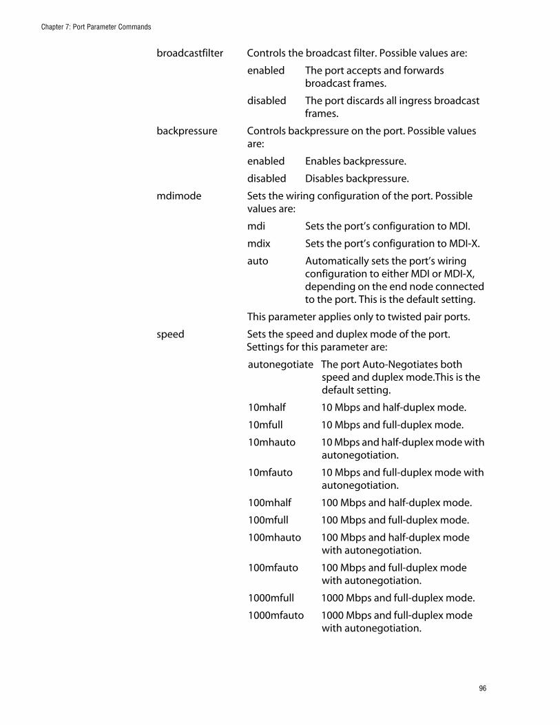
Chapter 7: Port Parameter Commands
broadcastfilter Controls the broadcast filter. Possible values are:
enabled The port accepts and forwards broadcast frames.
disabled The port discards all ingress broadcast frames.
backpressure Controls backpressure on the port. Possible values are:
enabled Enables backpressure.
disabled Disables backpressure.
mdimode Sets the wiring configuration of the port. Possible values are:
mdi Sets the port’s configuration to MDI.
mdix Sets the port’s configuration to MDI-X.
auto Automatically sets the port’s wiring configuration to either MDI or MDI-X, depending on the end node connected to the port. This is the default setting.
This parameter applies only to twisted pair ports.
speed Sets the speed and duplex mode of the port. Settings for this parameter are:
autonegotiate The port Auto-Negotiates both speed and duplex mode.This is the default setting.
10mhalf 10 Mbps and half-duplex mode.
10mfull 10 Mbps and full-duplex mode.
10mhauto 10 Mbps and half-duplex mode with autonegotiation.
10mfauto 10 Mbps and full-duplex mode with autonegotiation.
100mhalf 100 Mbps and half-duplex mode.
100mfull 100 Mbps and full-duplex mode.
100mhauto 100 Mbps and half-duplex mode with autonegotiation.
100mfauto 100 Mbps and full-duplex mode with autonegotiation.
1000mfull 1000 Mbps and full-duplex mode.
1000mfauto 1000 Mbps and full-duplex mode with autonegotiation.
96
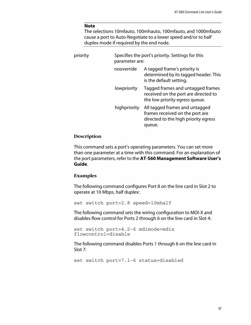
AT-S60 Command Line User’s Guide
NoteThe selections 10mfauto, 100mhauto, 100mfauto, and 1000mfauto cause a port to Auto-Negotiate to a lower speed and/or to half duplex mode if required by the end node.
priority Specifies the port’s priority. Settings for this parameter are:
nooverride A tagged frame’s priority is determined by its tagged header. This is the default setting.
lowpriority Tagged frames and untagged frames received on the port are directed to the low priority egress queue.
highpriority All tagged frames and untagged frames received on the port are directed to the high priority egress queue.
Description
This command sets a port’s operating parameters. You can set more than one parameter at a time with this command. For an explanation of the port parameters, refer to the AT-S60 Management Software User’s Guide.
Examples
The following command configures Port 8 on the line card in Slot 2 to operate at 10 Mbps, half duplex:
set switch port=2.8 speed=10mhalf
The following command sets the wiring configuration to MDI-X and disables flow control for Ports 2 through 6 on the line card in Slot 4:
set switch port=4.2-6 mdimode=mdix flowcontrol=disable
The following command disables Ports 1 through 6 on the line card in Slot 7:
set switch port=7.1-6 status=disabled
97

Chapter 7: Port Parameter Commands
The following command sets port priority to the high priority queue and activates the broadcast filter for Ports 5 and 8 on the line card in Slot 6 and Port 8 on the line card in Slot 12:
set switch port=6.5,8,12.8 priority=highpriority broadcastfilter=enabled
98

AT-S60 Command Line User’s Guide
SHOW SWITCH PORT
Syntax
show switch port[=port]
Parameters
port Specifies the port whose parameter settings you want to view. You can specify more than one port at a time. (For information on how to enter ports, refer to Specifying Ports on page 17.) If you do not specify a port, all ports are displayed.
Description
This command displays a port’s operating parameters, such as speed and duplex mode.
Examples
The following command displays the operating settings for all ports:
show switch port
The following command displays the operating settings for Port 4 on the line card in Slot 6:
show switch port=6.4
99
Chapter 8
Port Security Command
This chapter contains the following command:
❑ SET SWITCH PORT SECURITYMODE on page 101
NoteRemember to save your changes with the SAVE CONFIGURATION command.
NoteRefer to the AT-S60 Management Software User’s Guide for background information on port security.
100

AT-S60 Command Line User’s Guide
SET SWITCH PORT SECURITYMODE
Syntax
set switch port=port [securitymode=automatic|limited|secure|locked] [learn=integer] [intrusionaction=discard|trap|disable] [participate=yes|no]
Parameters
port Specifies the port where you want to set security. You can specify more than one port at a time. (For information on how to enter ports, refer to Specifying Ports on page 17.)
securitymode Specifies the port’s security mode. Options are:
automatic Disables security on the port. This is the default setting.
limited Sets the port to the Limited security mode. The port learns a limited number of dynamic MAC addresses, set with the LEARN parameter.
secure Sets the port to the Secure security mode. The port accepts frames based only on static MAC addresses. After you have activated this security mode on a port, you must enter the static MAC addresses of the nodes with frames the port is to accept. To add static MAC addresses, use the command ADD SWITCH FDB on page 216.
locked Sets the switch to the Locked security mode. The port stops learning new dynamic MAC addresses. The port forwards frames based on static MAC addresses and on those dynamic addresses it has already learned.
101

Chapter 8: Port Security Command
learn Specifies the maximum number of dynamic MAC addresses a port on the switch can learn. This parameter applies only to ports set to the Limited security mode. The range is 1 to 150 addresses. The default is 100.
intrusionaction Specifies the action taken by the port in the event port security is violated:
discard Discards invalid frames. This is the default setting.
trap Discards invalid frames and sends a management trap.
disable Discards invalid frames, sends a management trap, and disables the port.
participate Enables or disables the intrusion action on the port. This option only applies when a port’s intrusion action is set to trap or disable. This option does not apply when intrusion action is set to discard. Options are:
yes Enables the trap or disable intrusion action.
no Disables the trap or disable intrusion action. This is the default.
Description
This command sets and configures a port’s security mode. Only one mode can be active on a port at a time.
To view a port’s current security mode, use the command SHOW SWITCH PORT on page 99.
The management software displays a confirmation prompt whenever you perform this command. Responding with Y for yes completes your command, while N for no cancels the command.
Examples
The following command sets the security level to Locked for Ports 2, 6, and 8 on the line card in Slot 7:
set switch port=7.2,6,8 securitymode=locked
The Participate option is not required in this example since it is using the default intrusion action of discard.
102

AT-S60 Command Line User’s Guide
The following command sets the security level to Secure for Ports 1 through 4 on the line card in Slot 9 and the intrusion action to disable the ports:
set switch port=9.1-4 securitymode=secure intrusionaction=disable participate=yes
The Participate option is required in the above command to activate the disable intrusion action.
The following command sets the security level for Port 8 on the line card in Slot 4 to the Limited mode, specifies a limit of 5 dynamic MAC addresses, and sets the intrusion action to send a trap:
set switch port=4.8 securitymode=limited learn=5 intrusionaction=trap participate=yes
The following command changes the maximum number of learned MAC addresses to 200 on Ports 4 and 6 on the line card in Slot 12. The command assumes that the ports have already be set to the Limited security mode:
set switch port=12.4,6 learn=200
The following command returns Ports 1 to 4 on the line card in Slot 11 to the automatic security level, which, in effect, disables port security:
set switch port=11.1-4 securitymode=automatic
103
Chapter 9
Port Trunking Commands
This chapter contains the following commands:
❑ ADD SWITCH TRUNK on page 105
❑ CREATE SWITCH TRUNK on page 106
❑ DELETE SWITCH TRUNK on page 108
❑ DESTROY SWITCH TRUNK on page 109
❑ SET SWITCH TRUNK on page 110
❑ SHOW SWITCH TRUNK on page 111
NoteRemember to save your changes with the SAVE CONFIGURATION command.
NoteRefer to the AT-S60 Management Software User’s Guide for background information and guidelines on port trunking.
104
AT-S60 Command Line User’s Guide
ADD SWITCH TRUNK
Syntax
add switch trunk=name port=ports
Parameters
trunk Specifies the name of the port trunk to be modified. The name is case-sensitive.
port Specifies the port to be added to the port trunk. You can add more than one port at a time. (For information on how to enter ports, refer to Specifying Ports on page 17.)
Description
This command adds ports to an existing port trunk.
NoteTo initially create a port trunk, refer to CREATE SWITCH TRUNK on page 106.
Example
The following command adds Port 5 on the line card in Slot 2 to a port trunk called load22:
add switch trunk=load22 port=2.5
105

Chapter 9: Port Trunking Commands
CREATE SWITCH TRUNK
Syntax
create switch trunk=name port=ports speed=10_100m|1000m
Parameters
trunk Specifies the name of the trunk. The name can be up to 10 alphanumeric characters. No spaces or special characters are allowed. The name is case-sensitive.
port Specifies the ports of the trunk. (For information on how to enter ports, refer to Specifying Ports on page 17.)
speed Specifies the speed of the ports in the trunk. Options are:
10_100m The ports of the trunk are operating at 10 or 100 Mbps.
1000m The ports of the trunk are operating at 1000 Mbps.
Description
This command creates a port trunk. To create the trunk, you specify the ports on the switch that will constitute the trunk. You must also specify the operating speed of the ports.
CautionDo not connect the cables to the trunk ports on the switches until you have created the trunk in the management software. Connecting the cables before configuring the software creates a loop in your network topology. Data loops can result in broadcast storms and poor network performance.
Examples
The following command creates a port trunk using Ports 3 through 6 on an AT-8411 line card in Slot 2. The command names the trunk “load22.”
create switch trunk=load22 port=2.3-6 speed=10_100m
106

AT-S60 Command Line User’s Guide
The following command creates a port trunk of two 1000 Mbps ports on two AT-8413 line cards in Slots 3 and 4. It assigns the trunk the name “rm44:”
create switch trunk=rm44 port=3.1,4.1 speed=1000m
107

Chapter 9: Port Trunking Commands
DELETE SWITCH TRUNK
Syntax
delete switch trunk=name port=ports|all
Parameters
trunk Specifies the name of the trunk to be modified. The name is case-sensitive.
port Specifies the ports to be removed from the existing port trunk. To remove all ports, use the ALL option.
Description
This command removes ports from a port trunk.
NoteTo completely remove a port trunk from a switch, see DESTROY SWITCH TRUNK on page 109.
Example
The following command removes Port 9 on the line card in Slot 11 from a port trunk called Dev_trunk:
delete switch trunk=Dev_trunk port=11.9
108

AT-S60 Command Line User’s Guide
DESTROY SWITCH TRUNK
Syntax
destroy switch trunk=name
Parameter
trunk Specifies the name of the trunk to be deleted. The name is case-sensitive.
Description
This command deletes a port trunk from a switch. Once a port trunk has been deleted, the ports that made up the trunk can be connected to different end nodes.
CautionDisconnect the cables from the port trunk on the switch before destroying the trunk. Deleting a port trunk without first disconnecting the cables can create loops in your network topology. Data loops can result in broadcast storms and poor network performance.
Example
The following command deletes the trunk called load22 from the switch:
destroy switch trunk=load22
109

Chapter 9: Port Trunking Commands
SET SWITCH TRUNK
Syntax
set switch trunk=name speed=10_100m|1000m
Parameters
trunk Specifies the name of the port trunk whose speed you want to change. The name is case-sensitive.
speed Specifies the new speed of the trunk. Options are:
10_100m The ports of the trunk are operating at 10 or 100 Mbps.
1000m The ports of the trunk are operating at 1000 Mbps.
Description
This command changes the designated speed of an existing port trunk.
Example
The following command changes the designated speed of the port trunk named Load11 to 10 and 100 Mbps:
set switch trunk=Load11 speed=10_100m
110

AT-S60 Command Line User’s Guide
SHOW SWITCH TRUNK
Syntax
show switch trunk
Parameters
None.
Description
This command displays the names and ports of the port trunks on the switch.
Example
The following command displays port trunking information:
show switch trunk
111

Chapter 10
Port Mirroring Commands
This chapter contains the following commands:
❑ ADD SWITCH MIRROR on page 113
❑ CREATE SWITCH MIRROR on page 114
❑ DELETE SWITCH MIRROR on page 115
❑ DESTROY SWITCH MIRROR on page 116
❑ DISABLE SWITCH MIRROR on page 117
❑ ENABLE SWITCH MIRROR on page 118
❑ SET SWITCH MIRROR on page 119
❑ SHOW SWITCH MIRROR on page 120
NoteRemember to save your changes with the SAVE CONFIGURATION command.
NoteFor background information and guidelines on port mirroring, refer to the AT-S60 Management Software User’s Guide.
112

AT-S60 Command Line User’s Guide
ADD SWITCH MIRROR
Syntax
add switch mirror=destinationport port=sourceport
Parameters
mirror Specifies the destination port of the port mirror where you want to add more source ports. This port must already be functioning as a destination port of a port mirror. (For information on how to specify ports, refer to Specifying Ports on page 17.)
port Specifies the new source port of the port mirror. You can specify more than one port at a time, but there can be only one source port per line card.
Description
This command adds new source ports to an existing port mirror. Any source ports already assigned to the port mirror are retained and are not overwritten by the new source ports.
To create a port mirror, refer to CREATE SWITCH MIRROR on page 114. To view the ports of a port mirror, refer to SHOW SWITCH MIRROR on page 120.
Example
The following command adds Port 3 on the line card in Slot 11 as an additional source port to the existing port mirror that is using Port 1 on the line card in Slot 2 as the destination port:
add switch mirror=2.1 port=11.3
113

Chapter 10: Port Mirroring Commands
CREATE SWITCH MIRROR
Syntax
create switch mirror=destinationport port=sourceport
Parameters
mirror Specifies the destination port where the data is copied to and where the network analyzer is connected. You can specify only one destination port. (For information on how to specify ports, refer to Specifying Ports on page 17.)
port Specifies the source port whose traffic is to be mirrored. You can specify more than one port, but there can only be one source port per line card.
Description
This command creates a port mirror.
NoteTo view existing port mirrors, use the command SHOW SWITCH MIRROR on page 120.
Examples
The following command creates a port mirror where the destination port is Port 4 on the line card in Slot 4 and the source port is Port 6 on the same line card:
create switch mirror=4.4 port=4.6
The following command creates a port mirror where the destination port is Port 6 on the line card in Slot 12 and the source port is Port 8 on the line card in Slot 11:
create switch mirror=12.6 port=11.8
The following command creates a port mirror where the destination port is Port 8 on the line card in Slot 12 and the source ports are Port 8 on the line card in Slot 11 and Port 1 on the line card in Slot 9:
create switch mirror=12.8 port=11.8,9.1
114

AT-S60 Command Line User’s Guide
DELETE SWITCH MIRROR
Syntax
delete switch mirror=destinationport port=sourceport
Parameters
mirror Specifies the destination port of the port mirror where you want to remove source ports. This port must already be functioning as a destination port of a port mirror. (For information on how to specify ports, refer to Specifying Ports on page 17.)
ports Specifies the source port to be removed from an existing port mirror. You can specify more than one port at a time.
Description
This command removes a source port, or ports, from a port mirror.
NoteTo view the ports of a port mirror, see SHOW SWITCH MIRROR on page 120.
Example
The following command removes Port 2 on the line card in Slot 12 from the port mirror that is using Port 8 on the line card in Slot 2 as the destination port:
delete switch mirror=2.8 port=12.2
115

Chapter 10: Port Mirroring Commands
DESTROY SWITCH MIRROR
Syntax
destroy switch mirror=destinationport
Parameter
mirror Specifies the destination port of the port mirror you want to delete.
Description
This command deletes a port mirror. Once a port mirror has been deleted, the port that was functioning as the destination (mirror) port can be disconnected from the network analyzer and connected to an end node for normal network operations.
Example
The following command deletes the port mirror that is using Port 5 on the line card in Slot 7 as the destination port:
destroy switch mirror=7.5
116

AT-S60 Command Line User’s Guide
DISABLE SWITCH MIRROR
Syntax
disable switch mirror=destinationport
Parameter
mirror Specifies the destination port of the port mirror to be disabled.
Description
This command disables a port mirror. The source ports continue to forward traffic to and from their respective end nodes, but no traffic is copied to the destination port of the port mirror.
A port mirror is enabled when created. To view the current status of a port mirror, refer to SHOW SWITCH MIRROR on page 120.
Example
The following command disables the port mirror that is using Port 7 on the line card in Slot 2 as the destination port:
disable switch mirror=2.7
117

Chapter 10: Port Mirroring Commands
ENABLE SWITCH MIRROR
Syntax
enable switch mirror=destinationport
Parameter
mirror Specifies the destination port of the port mirror to be enabled.
Description
This command enables a port mirror. Traffic from the source ports is again copied to the destination port.
A port mirror is enabled when created. You would use this command if you had disabled a port mirror with the DISABLE SWITCH MIRROR command.
Example
The following command enables the port mirror that is using Port 5 on the line card in Slot 7 as the destination port:
enable switch mirror=7.5
118

AT-S60 Command Line User’s Guide
SET SWITCH MIRROR
Syntax
set switch mirror=destinationport port=sourceport
Parameters
mirror Specifies the destination port of the port mirror to which you want to add new source ports. This port must already be functioning as a destination port of a port mirror. (For information on how to specify ports, refer to Specifying Ports on page 17.)
port Specifies the new source port(s) for an existing port mirror. You can specify more than one port, but there can be only one source port per line card.
Description
This command specifies new source ports for an existing port mirror. It is similar to the ADD SWITCH MIRROR command. They both add new source ports to a port mirror. Where they differ is that with this command the new source ports replace the existing source ports. With the ADD SWITCH MIRROR command, the new source ports are added to the existing source ports.
Example
The following command specifies Port 4 on the line card in Slot 6 as the new source port for a port mirror. The destination port is Port 4 on the line card in Slot 1:
set switch mirror=1.4 port=6.4
119

Chapter 10: Port Mirroring Commands
SHOW SWITCH MIRROR
Syntax
show switch mirror
Parameters
None.
Description
This command displays the source and destination ports of port mirrors on the switch.
Example
The following command displays the switch mirror ports:
show switch mirror
120

Chapter 11
File System Commands
This chapter contains the following commands:
❑ COPY on page 122
❑ CREATE CONFIG on page 123
❑ DELETE FILE on page 124
❑ RENAME on page 125
❑ SET CONFIG on page 126
❑ SHOW FILE on page 127
NoteRefer to the AT-S60 Management Software User’s Guide for background information on the AT-S60 file system.
121

Chapter 11: File System Commands
COPY
Syntax
copy filename1.ext filename2.ext
Parameters
filename1.ext The name of the file to be copied.
filename2.ext The name of the new file.
Description
This command copies an existing file into a new file. The new filename must be a valid filename between 1 and 16 characters long. Valid characters are lowercase letters (a–z), uppercase letters (A–Z), digits (0–9), and the characters ~ ’ @ # $ % ^ & ( ) _ - { }. Invalid characters are ! * + = “| \ [ ] ; : ? / , < >.
Three-letter file extension, ext, can be any of the following: .cer, .cfg, .key and .csr. The extensions and their corresponding file types are shown in Table 1.
The original file and the new file must have the same extension.
Example
The following command creates a copy of a configuration file:
copy admin.cfg newadmin2.cfg
Table 1 File Name Extensions
Extension File Type
.img AT-S60 management software image
.cfg AT-S60 configuration file
.cer Public key certificate
.csr Public key certificate enrollment request
.key Encryption key file
122

AT-S60 Command Line User’s Guide
CREATE CONFIG
Syntax
create config=filename
Parameter
config Specifies the name of the configuration file.
Description
This command creates a configuration file containing the commands required to recreate the current dynamic configuration of the switch.
The CONFIG parameter specifies the name of the configuration file to create. The file extension must be .cfg. If the file already exists, it is replaced. If the file does not exist it is created.
The filename must be a valid filename between 1 and 16 characters long. Valid characters are lowercase letters (a–z), uppercase letters (A–Z), digits (0–9), and the characters ~ ’ @ # $ % ^ & ( ) _ - { }. Invalid characters are: ! * + = “| \ [ ] ; : ? / , < >. Wildcards are not allowed.
Example
The following command saves the current dynamic configuration to a file called boot.cfg:
create config=boot.cfg
123

Chapter 11: File System Commands
DELETE FILE
Syntax
delete file=filename
Parameter
file Specifies the name of the file or files to be deleted.
Description
This command deletes the specified file or files. Wildcards are allowed in the name elements of the file identifier.
The filename must be a valid filename between 1 and 16 characters long. Valid characters are lowercase letters (a–z), uppercase letters (A–Z), digits (0–9), and the characters ~ ’ @ # $ % ^ & ( ) _ - { }. Invalid characters are ! * + = “| \ [ ] ; : ? / , < >. Wildcards are not allowed in the filename extension.
CautionCaution must be taken when deleting files such as configuration files because they contain information which is vital to the operation of the switch.
Example
The following command deletes the configuration file named test.cfg:
delete file=test.cfg
124

AT-S60 Command Line User’s Guide
RENAME
Syntax
rename filename1 filename2
Parameters
None.
Description
This command renames the specified file. The source file name must identify an existing file, and the destination file name must not already exist. The source and destination file extensions must be the same. For table of file extension names, see COPY on page 122.
Example
The following command renames the boot.cfg file to saveboot.cfg:
rename boot.cfg saveboot.cfg
125

Chapter 11: File System Commands
SET CONFIG
Syntax
set config=filename
Parameter
config Specifies the name of a configuration file.
Description
This command sets the configuration file for a switch. The switch will use the configuration file the next time it is rebooted or power cycled.
The configuration file must already exist in the switch’s file system. To view the files in a switch’s file system, see SHOW FILE on page 127. Configuration files have a .cfg extension.
To view the name of the configuration file the switch is currently using, see SHOW CONFIG on page 51.
You do not need to use the SAVE CONFIGURATION command with this command. A change to the current configuration file is saved automatically.
Example
The following command sets the boot configuration file to switch22.cfg:
set config=switch22.cfg
The switch uses the switch22.cfg configuration file the next time it is reset.
126

AT-S60 Command Line User’s Guide
SHOW FILE
Syntax
show file=filename
Parameter
file Specifies the name of the file to be displayed.
Description
This command displays a list of the files that are stored on the switch. Wildcards can be used to replace any part of the file name to allow a more selective display. The following extensions are permitted:
❑ .cer
❑ .cfg
❑ .csr
❑ .img
❑ .key
If you specify a configuration file, the contents of the file are displayed.
Examples
The following command lists all the configuration files on the switch:
show file=*.cfg
The following command displays the contents of the configuration file boot.cfg:
show file=boot.cfg
The following command lists the key files:
show file=*.key
127

Chapter 12
File Download and Upload Commands
This chapter contains the following commands:
❑ LOAD on page 129
❑ UPLOAD on page 134
NoteFor background information on downloading and uploading software images and configuration files, refer to the AT-S60 Management Software User’s Guide.
128

AT-S60 Command Line User’s Guide
LOAD
Syntax
load method=tftp|xmodem|remoteswitch destfile=filename server=ipaddress file=filename switchlist=switches
Parameters
method Specifies the method of download. Options are:
tftp Specifies a TFTP download. To use this option, there must be a network node with TFTP server software. The file to download onto the switch must be stored on the TFTP server. You can use the TFTP option from either a local or Telnet management session.
xmodem Specifies an Xmodem download via a local management session. This download can only upgrade the switch to which the management station is connected. You cannot use this option to upgrade other switches in an enhanced stack. You can only use this option from a local management session.
remoteswitch Indicates that the download will be from a master switch to other switches in an enhanced stack. This option must be used with the SWITCHLIST option. (The REMOTESWITCH option can only be used from a master switch.)
129

Chapter 12: File Download and Upload Commands
destfile Specifies the name under which the file is to be stored on the switch.
server Specifies the IP address of network node containing the TFTP server software. This parameter is required for a TFTP download.
file Specifies the path and filename of the file you are downloading onto the switch. This parameter is required for a TFTP download.
switchlist Specifies the switches in an enhanced stack to which to download the software image or file from the master switch. Switch numbers are displayed with the SHOW REMOTELIST command. This parameter is used with the REMOTESWITCH parameter.You can specify more than one switch at a time (for example, 1,3,4).
Description
You can use this command to download the following types of files onto the switch:
❑ AT-S60 software image
❑ Configuration file
❑ Public key certificate
❑ Public key certificate enrollment request
❑ Encryption key
This command can download files in the following ways:
❑ From a management workstation to a slave or master switch using Xmodem or TFTP
❑ From a master switch to other switches in an enhanced stack
The METHOD parameter states the type of download. There are three possible types of downloads. A TFTP download uses the TFTP client software on the switch to download a file from a TFTP server on your network. The file that you are downloading must be stored on the TFTP server. You can perform this type of download from either a local or Telnet management session.
130

AT-S60 Command Line User’s Guide
The XMODEM download method uses the XMODEM utility to download a file onto the switch from a terminal or computer with a terminal emulator program connected to the RS-232 Terminal Port on the AT-8401 fabric management card. This type of download can only be performed from a local management session and the file to download must be stored on the computer connected to the AT-8401 management card.
The REMOTESWITCH parameter downloads a file from the master switch to another switch in the enhanced stack. You can perform this type of download from a local or remote management session.
The DESTFILE parameter specifies the name that the file is to be store as on the switch. This parameter is only used with a TFTP download.
When specifying the new name of a downloaded file, you must be sure to give it the correct three-letter extension, depending on the file type. The extensions are shown in Table 1.
Before downloading files, note the following:
❑ To download a new version of the AT-S60 management software image onto a switch, specify the DESTFILE filename as “ATS60.IMG”. Do not give the image file any other name.
❑ When you download a new configuration file onto a switch, the file is stored in the switch’s file system, but it is not automatically activated on the switch. If you want the switch to use a newly downloaded configuration file the next time you reboot the switch, see SET CONFIG on page 126.
Table 1 File Name Extensions
Extension File Type
.img AT-S60 management software image
.cfg AT-S60 configuration file
.cer Public key certificate
.csr Public key certificate enrollment request
.key Encryption key file
131

Chapter 12: File Download and Upload Commands
❑ If you are downloading files switch-to-switch using the REMOTESWITCH command, use the SHOW REMOTELIST command first to view the switch numbers. (This also allows the management software to determine which switches are in the enhanced stack.)
❑ In networks consisting of several AT-8400 Switches, you can simplify an upgrade procedure by first upgrading a master switch to the latest software version via a local management session. Then, download the new software switch-to-switch from the master switch to the slave switches in the same subnet.
❑ You cannot download the AT-S60 software image onto an AT-8000 Series switch.
CautionOnce an AT-S60 image file has been transferred to the AT-8401 Management card, the card writes the image to flash memory. This process takes approximately a minute to complete. Do not interrupt the process by resetting or power cycling the switch.
Examples
The following command uses Xmodem to download a new AT-S60 software image:
load method=xmodem destfile=ats60.img
When downloading the management software image, the destination filename must be ATS60.IMG.
All Xmodem transfers must be performed from a local management session. Xmodem is not supported from a Telnet management session.
After you have entered the command, the management software displays a confirmation prompt followed by another prompt instructing you to begin the file transfer. To start the transfer, use your terminal emulation program to specify the location of the AT-S60 software image file stored on your workstation.
The following command uses Xmodem to download a new AT-S60 configuration file to the switch and gives it the name sw12_boot.cfg:
load method=xmodem destfile=sw12_boot.cfg
Since this is another Xmodem transfer, it must be performed from a local management session. After entering this command, you must specify the location of the configuration file stored on your workstation using your terminal emulation program.
132

AT-S60 Command Line User’s Guide
The following command downloads a new AT-S60 image to the switch using TFTP. Since this is a TFTP download, you can perform this command from either a local or Telnet management session. The command specifies the IP address of the TFTP server and the location of the image file on the server.
load method=tftp destfile=ats60.img server=149.166.22.12 file=c:\software\ats60.img
The following command downloads the AT-S60 image file on the master switch to switches 1 and 4 in an enhanced stack. (Switch numbers are displayed using the SHOW REMOTELIST command.)
load method=remoteswitch destfile=ats60.img switchlist=1,4
You can use the REMOTESWITCH option from either a local or a Telnet management session. However, the switch on which you are executing the command must be a master switch of the enhanced stack.
The following command downloads the AT-S60 configuration file on the master switch to switch 2 in an enhanced stack. The VERBOSE option is included to display download status messages.
load method=remoteswitch destfile=ats60.cfg switchlist=2 verbose=yes
133

Chapter 12: File Download and Upload Commands
UPLOAD
Syntax
upload method=tftp|xmodem destfile=filename server=ipaddress file=filename
Parameters
method Specifies the method of the upload. The options are:
tftp Specifies a TFTP upload. To use this option, there must be TFTP server software on a network node. You can use this option from either a local or Telnet management session.
xmodem Indicates that the upload will be performed using Xmodem. This option is supported only from a local management session.
destfile Specifies the path and filename where the file is to be saved on the TFTP server. This parameter is used with a TFTP upload.
server Specifies the IP address of the network node containing the TFTP server software. This parameter is used with a TFTP upload.
file Specifies the name of the file you are uploading from the switch.
Description
This command can upload any of the following types of files from a switch to a management workstation or TFTP server:
❑ AT-S60 software image
❑ Configuration file
❑ Public key certificate
❑ Public key certificate enrollment request
❑ Encryption key
134

AT-S60 Command Line User’s Guide
The METHOD parameter states the type of upload. There are two possible types of uploads. A TFTP upload uses the TFTP client software on the switch to upload a file from the switch to a TFTP server on your network. You can perform this type of upload from either a local or Telnet management session.
The XMODEM download method uses the XMODEM utility to upload a file from the switch to a terminal or computer with a terminal emulator program connected to the RS-232 Terminal Port on the AT-8401 management card. This type of upload must be performed from a local management session.
The DESTFILE parameter specifies the name that the file is to be store as on the switch. This parameter is only used with a TFTP upload.
The SERVER parameter specifies the IP address of the network node containing the TFTP server software. The uploaded file will be stored on this node. This parameter is only required for a TFTP upload.
The FILE parameter specifies the name of the file that you want to upload from the switch. To view the files stored in the file system of a switch, see SHOW FILE on page 127.
Before uploading a file, note the following:
❑ When naming an uploaded file, you should give it the three-letter extension that corresponds to its file type. The extensions are listed in Table 2.
❑ To upload the AT-S60 management image, specify “ATS60.IMG” as the value for the FILE parameter. (The AT-S60 management image is not listed in a switch’s file system.)
Table 2 File Name Extensions
Extension File Type
.img AT-S60 management software image
.cfg AT-S60 configuration file
.cer Public key certificate
.csr Public key certificate enrollment request
.key Encryption key file
135
Chapter 12: File Download and Upload Commands
Examples
The following command uses Xmodem to upload a switch’s configuration file called sw22_boot.cfg from a local management session:
upload method=xmodem file=sw22_boot.cfg
After entering the command, use your terminal emulator program to indicate where you want to store the file on your computer and its filename.
The following command uploads the switch’s AT-S60 image to the workstation:
upload method=xmodem file=ast60.img
The following command uploads a switch’s configuration file using TFTP:
upload method=tftp destfile=c:\software\switch4.cfg server=149.36.11.21 file=switch4.cfg
136

Chapter 13
STP Commands
This chapter contains the following commands:
❑ ACTIVATE STP on page 138
❑ DISABLE STP on page 139
❑ ENABLE STP on page 140
❑ RESET STP on page 141
❑ SET STP on page 142
❑ SET STP PORT on page 145
❑ SHOW STP on page 147
NoteRemember to save your changes with the SAVE CONFIGURATION command.
NoteRefer to the AT-S60 Management Software User’s Guide for background information on the Spanning Tree Protocol (STP).
137

Chapter 13: STP Commands
ACTIVATE STP
Syntax
activate stp
Parameters
None.
Description
Use this command to designate STP as the active spanning tree on the switch. You cannot configure the STP parameters until you have designated it as the active spanning tree with this command.
NoteActivating STP reboots the switch. You are notified of this requirement by a prompt displayed by this command.
When you activate STP with this command, another prompt is displayed inquiring if you want to enable or disable the protocol when it is activated. If you enable the protocol, the management software designates STP as the active spanning tree protocol on the switch and enables it so that it is immediately active after the switch reboots. If you choose not to enable it, the management software still designates STP as the active spanning tree protocol on the switch, but does not enable it. The latter selection is appropriate if you want to configure STP parameter settings before enabling the protocol on the switch. To enable STP, use ENABLE STP on page 140.
Example
The following command designates STP as the active spanning tree:
activate stp
138

AT-S60 Command Line User’s Guide
DISABLE STP
Syntax
disable stp
Parameters
None.
Description
This command disables the Spanning Tree Protocol on the switch. The default setting for STP is disabled. To view the current status of STP, refer to SHOW STP on page 147.
Example
The following command disables STP:
disable stp
139
Chapter 13: STP Commands
ENABLE STP
Syntax
enable stp
Parameters
None.
Description
This command enables the Spanning Tree Protocol on the switch. The default setting for STP is disabled. To view the current status of STP, refer to SHOW STP on page 147.
NoteYou cannot enable STP until after you have activated it with the ACTIVATE STP command.
Only one spanning tree protocol (that is, STP, RSTP, or MSTP) can be active on the switch at a time.
Example
The following command enables STP on the switch:
enable stp
140

AT-S60 Command Line User’s Guide
RESET STP
Syntax
reset stp
Parameters
None.
Description
This command returns all STP bridge and port parameters to the default settings. STP must be disabled in order for you to use this command. To disable STP, refer to DISABLE STP on page 139.
Example
The following command resets the STP parameter settings to their default values:
reset stp
141

Chapter 13: STP Commands
SET STP
Syntax
set stp [default] [priority=priority] [hellotime=hellotime] [forwarddelay=forwarddelay] [maxage=maxage]
Parameters
default Returns all bridge and port STP settings to the default values. This parameter cannot be used with any other command parameter. (This parameter performs the same function as the RESET STP command.)
priority Specifies the priority number for the bridge. This number is used in determining the root bridge for STP. The bridge with the lowest priority number is selected as the root bridge. If two or more bridges have the same priority value, the bridge with the numerically lowest MAC address becomes the root bridge.
The range is 0 to 61,440 in increments of 4,096. The range is divided into sixteen increments, as shown in the following table. You specify the increment that represents the desired bridge priority value. The default value is 32,768 (increment 8).
Table 3 Bridge Priority Value Increments
IncrementBridge Priority
IncrementBridge Priority
0 0 8 32768
1 4096 9 36864
2 8192 10 40960
3 12288 11 45056
4 16384 12 49152
5 20480 13 53248
6 24576 14 57344
7 28672 15 61440
142

AT-S60 Command Line User’s Guide
hellotime Specifies the time interval between generating and sending configuration messages by the bridge. This parameter can be from 1 to 10 seconds. The default is 2 seconds.
forwarddelay Specifies the waiting period before a bridge changes to a new state, for example, becomes the new root bridge after the topology changes. If the bridge transitions too soon, all links may not have had time to adapt to the change, resulting in network loops. The range is 4 to 30 seconds. The default is 15 seconds.
maxage Specifies the length of time after which stored bridge protocol data units (BPDUs) are deleted by the bridge. All bridges in a bridged LAN use this aging time to test the age of stored configuration messages called bridge protocol data units (BPDUs). For example, if you use the default 20, all bridges delete current configuration messages after 20 seconds. The range is 6 to 40 seconds. The default is 20 seconds.
NoteThe value for the maxage parameter must be less than (2 x (hellotime +1)) and less than (2 x (forwarddelay -1)).
Description
This command sets the following STP parameters
❑ Bridge priority
❑ Hello time
❑ Forwarding delay
❑ Maximum age time
This command can also disable STP and return the STP parameters to their default settings.
NoteYou can use this command only if STP is designated as the active spanning tree protocol on the switch. See ACTIVATE STP on page 138.
143

Chapter 13: STP Commands
Examples
The following command sets the switch’s bridge priority value to 45,056 (increment 11):
set stp priority=11
The following command sets the hello time to 7 seconds and the forwarding delay to 25 seconds:
set stp hellotime=7 forwarddelay=25
The following command returns all STP parameters on the switch to the default values:
set stp default
144

AT-S60 Command Line User’s Guide
SET STP PORT
Syntax
set stp port=port|all [default] [portcost=portcost] [portpriority=portpriority]
Parameters
port Specifies the port (that is, slot.port) you want to configure. You can specify more than one port at a time. To configure all ports, enter ALL. (For information on how to enter ports, refer to Specifying Ports on page 17.)
default Returns the port’s STP settings to the default values. This parameter can only be used when STP is enabled on the switch and it cannot be used with any other command parameter.
portcost Specifies the port’s cost. The spanning tree algorithm uses the cost parameter to decide which port provides the lowest cost to the root bridge for that LAN. The range is 0 (Auto-Detect) to 200,000,000. The default setting is Auto-Detect, which automatically sets port cost according to the speed of the port. The default settings for Auto-Detect are 100 for a 10 Mbps port, 10 for a 100 Mbps port, and 4 for a 1 Gbps port.
portpriority Specifies the port’s priority. This parameter is used as a tie breaker when two or more ports are determined to have equal costs to the root bridge. The range is 0 to 240 in increments of 16. There are sixteen increments. The increments are listed in Table 4. You specify the increment of the desired value. The default is 128 (increment 8).
145

Chapter 13: STP Commands
Description
This command configures the following STP parameter settings for a switch port:
❑ Port cost
❑ Port priority
Example
The following command sets the port cost to 15 and the port priority to 192 (increment 12) for Port 6 on the line card in Slot 10:
set stp port=10.6 portcost=15 portpriority=12
Table 4 Port Priority Value Increments
IncrementBridge Priority
IncrementBridge Priority
0 0 8 128
1 16 9 144
2 32 10 160
3 48 11 176
4 64 12 192
5 80 13 208
6 96 14 224
7 112 15 240
146

AT-S60 Command Line User’s Guide
SHOW STP
Syntax
show stp [port=port]
Parameter
port Specifies the port whose STP parameters you want to view. You can specify more than one port at a time. (For information on how to enter ports, refer to Specifying Ports on page 17.)
Description
This command displays the current values for the following STP parameters:
❑ STP status
❑ Bridge identifier
❑ Bridge priority
❑ Hello time
❑ Forwarding delay
❑ Maximum age timer
You can also use this command to view the following STP parameter settings for a switch port:
❑ Path cost
❑ Port priority
❑ Port STP state
Examples
The following command displays the switch’s STP settings:
show stp
The following command displays the STP settings for Ports 1 through 4 on the line card in Slot 5:
show stp port=5.1-4
147

Chapter 14
RSTP Commands
This chapter contains the following commands:
❑ ACTIVATE RSTP on page 149
❑ DISABLE RSTP on page 150
❑ ENABLE RSTP on page 151
❑ RESET RSTP on page 152
❑ SET RSTP on page 153
❑ SET RSTP PORT on page 156
❑ SHOW RSTP on page 159
NoteRemember to save your changes with the SAVE CONFIGURATION command.
NoteRefer to the AT-S60 Management Software User’s Guide for background information on Rapid Spanning Tree Protocol (RSTP).
148

AT-S60 Command Line User’s Guide
ACTIVATE RSTP
Syntax
activate rstp
Parameters
None.
Description
Use this command to designate RSTP as the active spanning tree on the switch. Once you have selected RSTP, you can enable or disable it using the ENABLE RSTP and DISABLE RSTP commands. RSTP is active on a switch only after you have designated it as the active spanning tree with this command and enabled it with the ENABLE RSTP command.
NoteA change to the active spanning tree protocol with this command will reboot the switch.
When you activate RSTP, a prompt is displayed inquiring if you want to enable or disable the protocol when it is activated. If you enable the protocol, the management software designates RSTP as the active spanning tree protocol on the switch and enables it so that it is immediately active after the switch reboots. If you choose not to enable it, the management software designates RSTP as the active spanning tree protocol on the switch, but does not enable it. The latter selection is appropriate if you want to configure RSTP parameter settings before enabling the protocol on the switch. To enable RSTP, use ENABLE RSTP on page 151.
Example
The following command designates RSTP as the active spanning tree:
activate rstp
149

Chapter 14: RSTP Commands
DISABLE RSTP
Syntax
disable rstp
Parameters
None.
Description
This command disables the Rapid Spanning Tree Protocol on the switch. To view the current status of RSTP, use the SHOW RSTP command.
Example
The following command disables RSTP:
disable rstp
150

AT-S60 Command Line User’s Guide
ENABLE RSTP
Syntax
enable rstp
Parameters
None.
Description
This command enables the Rapid Spanning Tree Protocol on the switch. The default setting for RSTP is disabled. To view the current status of RSTP, use the SHOW RSTP command.
You cannot enable RSTP until you have activated it with the ACTIVATE RSTP command.
Only one spanning tree protocol, STP, RSTP, or MSTP can be active on the switch at a time.
Example
The following command enables RSTP:
enable rstp
151

Chapter 14: RSTP Commands
RESET RSTP
Syntax
reset rstp
Parameters
None.
Description
This command returns all RSTP bridge and port parameters to the default settings. RSTP must be disabled before you can use this command. To disable RSTP, refer to DISABLE RSTP on page 150.
Example
The following command resets RSTP:
reset rstp
152

AT-S60 Command Line User’s Guide
SET RSTP
Syntax
set rstp [default] [priority=priority] [hellotime=hellotime] [forwarddelay=forwarddelay] [maxage=maxage][forceversion=forcestpcompatible|normalrstp]
Parameters
default Returns all bridge and port RSTP settings to the default values. This parameter cannot be used with any other command parameter. (This parameter performs the same function as the RESET RSTP command.)
priority Specifies the priority number for the bridge. This number is used in determining the root bridge for RSTP. The bridge with the lowest priority number is selected as the root bridge. If two or more bridges have the same priority value, the bridge with the numerically lowest MAC address becomes the root bridge. The range is 0 to 61,440 in increments of 4,096. The range is divided into sixteen increments, as shown in the following table. You specify the increment that represents the desired bridge priority value. The default value is 32,768, which corresponds to increment 8.
Table 5 Bridge Priority Value Increments
IncrementBridge Priority
IncrementBridge Priority
0 0 8 32768
1 4096 9 36864
2 8192 10 40960
3 12288 11 45056
4 16384 12 49152
5 20480 13 53248
6 24576 14 57344
7 28672 15 61440
153

Chapter 14: RSTP Commands
hellotime Specifies the time interval between generating and sending configuration messages by the bridge. The range of this parameter is from 1 to 10 seconds. The default is 2 seconds.
forwarddelay Specifies the waiting period before a bridge changes to a new state, for example, becomes the new root bridge after the topology changes. If the bridge transitions too soon, not all links may have yet adapted to the change, resulting in network loops. The range is 4 to 30 seconds. The default is 15 seconds. This parameter effects only those ports operating in the STP compatible mode.
maxage Specifies the length of time, in seconds, after which stored bridge protocol data units (BPDUs) are deleted by the bridge. All bridges in a bridged LAN use this aging time to test the age of stored configuration messages called bridge protocol data units (BPDUs). For example, if you use the default value of 20, all bridges delete current configuration messages after 20 seconds. The range of this parameter is 6 to 40 seconds. The default is 20 seconds.
NoteThe value for the maxage parameter must be less than (2 x (hellotime +1)) and less than (2 x (forwarddelay -1)).
forceversion This parameter lets you choose between:
forcestpcompatible The bridge uses the RSTP parameter settings, but transmits only STP BPDU packets from the ports.
normalrstp The bridge uses RSTP. It transmits RSTP BPDU packets, except on ports connected to bridges running STP. This is the default setting.
Description
This command configures the following RSTP parameter settings:
❑ Bridge priority
❑ Hello time
154

AT-S60 Command Line User’s Guide
❑ Forwarding delay
❑ Maximum age time
❑ Port priority
❑ Force version of STP or normal RSTP
Examples
The following command returns all RSTP parameter settings to their default values:
set rstp default
The following command sets the bridge priority to 20480 (increment 5), the hello time to 5 seconds, and the forwarding delay to 20 seconds:
set rstp priority=5 hellotime=5 forwarddelay=20
The following command uses the FORCEVERSION parameter to configure the bridge to use the RSTP parameters but to transmit only STP BPDU packets:
set rstp forceversion=forcestpcompatible
155

Chapter 14: RSTP Commands
SET RSTP PORT
Syntax
set rstp port=port|all [default] [portcost=portcost|auto] [portpriority=portpriority][edgeport=yes|no] [pointtopoint=yes|no|autoupdate][migrationcheck=yes|no]
Parameters
port Specifies the port (that is, slot.port) you want to configure. You can specify more than one port at a time. To configure all ports, enter ALL. (For information on how to enter ports, refer to Specifying Ports on page 17.)
default Returns the port’s RSTP settings to their default values. This parameter performs the same function as the RESET RSTP command.
portcost Specifies the port’s cost. The spanning tree algorithm uses the cost parameter to decide which port provides the lowest cost to the root bridge for that LAN. The range is 0 to 200,000,000. The default setting is Auto-Detect, which automatically sets port cost according to the speed of the port. Table 6 lists the port cost with Auto-Detect.
Table 6 RSTP Auto-Detect Port Costs
Port Speed Port Cost
10 Mbps 2,000,000
100 Mbps 200,000
1000 Mbps 20,000
156

AT-S60 Command Line User’s Guide
portpriority Specifies the port’s priority. This parameter is used as a tie breaker when two or more ports are determined to have equal costs to the root bridge. The range is 0 to 240 in increments of 16. There are sixteen increments. You specify the increment that corresponds to the desired value. The default is 128, which is increment 8.
edgeport Defines whether the port is functioning as an edge port. An edge port is connected to a device operating at half-duplex mode and is not connected to any device running STP or RSTP. Selections are:
yes The port is an edge port. This is the default.
no The port is not an edge port.
pointtopoint Defines whether the port is functioning as a point-to-point port. This type of port is connected to a device operating at full-duplex mode. Selections are:
yes The port is an point-to-point port.
no The port is not an point-to-point port.
autoupdate The port’s status is determined automatically. This is the default.
Table 7 Port Priority Value Increments
IncrementBridge Priority
IncrementBridge Priority
0 0 8 128
1 16 9 144
2 32 10 160
3 48 11 176
4 64 12 192
5 80 13 208
6 96 14 224
7 112 15 240
157

Chapter 14: RSTP Commands
migrationcheck This parameter resets a RSTP port, allowing it to send RSTP BPDUs. When an RSTP bridge receives STP BPDUs on an RSTP port, the port transmits STP BPDUs. The RSTP port continues to transmit STP BPDUs indefinitely. Set the migrationcheck parameter to yes to reset the RSTP port to transmit RSTP BPDUs.
NoteEach time a RSTP port is reset by receiving STP BPDUs, set the migrationcheck parameter to yes, allowing the port to send RSTP BPDUs.
Description
This command sets a port’s RSTP settings.
Examples
The following command sets port cost to 1,000,000 and port priority to 224 (increment 14) on Port 4 on the line card in Slot 9:
set rstp port=9.4 portcost=1000000 portpriority=14
The following command changes Ports 6 to 8 on the line card in Slot 10 so they are not considered edge ports:
set rstp port=10.6-8 edgeport=no
The following command returns Port 7 on the line card in Slot 2 to the default RSTP settings:
set rstp port=2.7 default
158

AT-S60 Command Line User’s Guide
SHOW RSTP
Syntax
show rstp [portconfig=port|portstate=port]
Parameters
portconfig Displays the RSTP port settings. You can specify more than one port at a time.
portstate Displays the RSTP port status. You can specify more than one port at a time.
Description
You can use this command to display the RSTP parameter settings. Values are displayed for the following parameters:
❑ RSTP status
❑ Bridge identifier
❑ Bridge priority
❑ Hello time
❑ Maximum aging
❑ Forwarding delay
You can also use this command to view the following RSTP parameter settings for a switch port:
❑ Port cost
❑ Port priority
❑ Edge and point-to-point status
Examples
The following command displays the bridge’s RSTP settings:
show rstp
The following command displays the RSTP port settings for ports 1 to 4 on the module in slot 4:
show rstp portconfig=4.1-4
159

Chapter 14: RSTP Commands
The following command displays RSTP port status for port 5 on the module in slot 8:
show rstp portstate=8.5
160
Chapter 15
MSTP Commands
This chapter contains the following commands:
❑ ACTIVATE MSTP on page 163
❑ ADD MSTP on page 164
❑ CREATE MSTP on page 165
❑ DELETE MSTP on page 166
❑ DESTROY MSTP MSTI on page 167
❑ DISABLE MSTP on page 168
❑ ENABLE MSTP on page 169
❑ RESET MSTP on page 170
❑ SET MSTP on page 171
❑ SET MSTP CIST on page 174
❑ SET MSTP MSTI on page 175
❑ SET MSTP MSTIVLANASSOC on page 177
❑ SET MSTP PORT on page 178
❑ SHOW MSTP on page 181
NoteRemember to save your changes with the SAVE CONFIGURATION command.
161

Chapter 15: MSTP Commands
NoteRefer to the AT-S60 Management Software User’s Guide for background information on the Multiple Spanning Tree Protocol (MSTP).
162

AT-S60 Command Line User’s Guide
ACTIVATE MSTP
Syntax
activate mstp
Parameters
None.
Description
This command designates MSTP as the active spanning tree on the switch. Only one spanning tree protocol (that is, STP, RSTP, or MSTP) can be active on the switch at a time.
NoteChanging the active spanning tree protocol reboots the switch.
When you activate MSTP, a prompt is displayed inquiring if you want to enable or disable the protocol when it is activated. If you select to enable the protocol, the management software designates MSTP as the active spanning tree protocol and enables it so that it is immediately active after the switch reboots. If you choose not to enable it, the management software designates MSTP as the active spanning tree protocol on the switch, but does not enable it. The latter selection is appropriate if you want to configure MSTP parameter settings before enabling the protocol on the switch. To enable MSTP, use ENABLE MSTP on page 169.
Example
The following command designates MSTP as the active spanning tree:
activate mstp
163

Chapter 15: MSTP Commands
ADD MSTP
Syntax
add mstp mstiid=mstiid mstivlanassoc=vids
Parameters
mstiid Specifies the ID of the multiple spanning tree instance (MSTI) to which you want to associate VLANs. You can specify only one MSTI ID at a time. The range is 1 to 15.
mstivlanassoc Specifies the VID of the VLAN you want to associate with the MSTI ID. You can specify more than one VID at a time (for example, 2,5,44).
Description
This command associates VLANs to a MSTI.
The MSTIID parameter specifies the MSTI ID. The MSTI must already exist on the switch. To create a spanning tree instance, see CREATE MSTP on page 165.
The MSTIVLANASSOC parameter specifies the VIDs of the VLANs you want to associate with the MSTI. The VLANs must already exist on the switch. Any VLANs already associated with the MSTI are retained. If you want to add VLANs to a MSTI while removing those already associated to it, see SET MSTP MSTIVLANASSOC on page 177.
Examples
This command associates the VLAN with the VID 4 to MSTI ID 8:
add mstp mstiid=8 mstivlanassoc=4
This command associates the VLANs with the VIDs 24 and 44 to MSTI ID 11:
add mstp mstiid=11 mstivlanassoc=24,44
164

AT-S60 Command Line User’s Guide
CREATE MSTP
Syntax
create mstp mstiid=mstiid [mstivlanassoc=vids]
Parameters
mstiid Specifies the MSTI ID of the spanning tree instance you want to create. You can specify only one MSTI ID at a time. The range is 1 to 15.
mstivlanassoc Specifies the VID of the VLAN you want to associate with the MSTI ID. You can specify more than one VID at a time (for example, 2,5,44).
Description
This command creates an MSTI ID and associates VLANs to the new spanning tree instance.
The MSTIID parameter specifies the new MSTI ID.
The MSTIVLANASSOC parameter specifies the VID of the VLAN you want to associate with the new MSTI. The VLAN must already exist on the switch. You can specify more than one VLAN, If you do not specify any VLANs, you can add them later using ADD MSTP on page 164 or SET MSTP MSTIVLANASSOC on page 177.
Examples
This command creates the MSTI ID 8 and associates the VLAN with the VID 4 to it:
create mstp mstiid=8 mstivlanassoc=4
This command creates the MSTI ID 11 and associates the VLANs with the of VIDs of 24 and 44 to it:
create mstp mstiid=11 mstivlanassoc=24,44
165

Chapter 15: MSTP Commands
DELETE MSTP
Syntax
delete mstp mstiid=mstiid mstivlanassoc=vids
Parameters
mstiid Specifies the MSTI ID of the spanning tree instance where you want to remove VLANs. You can specify only one MSTI ID at a time. The range is 1 to 15.
mstivlanassoc Specifies the VID of the VLAN you want to remove from the spanning tree instance. You can specify more than one VID at a time (for example, 2,5,44).
Description
This command removes a VLAN from a spanning tree instance. A VLAN removed from a spanning tree instance is automatically returned to CIST.
The MSTIID parameter specifies the MSTI ID.
The MSTIVLANASSOC parameter specifies the VIDs of the VLANs you want to remove from the spanning tree instance.
Examples
This command deletes the VLAN with the VID 4 from MSTI ID 8:
delete mstp mstiid=8 mstivlanassoc=4
This command deletes the VLANs with the VIDs 24 and 44 from MSTI ID 11:
delete mstp mstiid=11 mstivlanassoc=24,44
166
AT-S60 Command Line User’s Guide
DESTROY MSTP MSTI
Format
destroy mstp mstiid=mstiid
Parameter
mstiid Specifies the MSTI ID of the spanning tree instance you want to delete. You can specify only one MSTI ID at a time. The range is 1 to 15.
Description
This command deletes a spanning tree instance. VLANs associated to a deleted instance are returned to CIST.
Example
This example deletes the spanning tree instance 4:
destroy mstp mstiid=4
167

Chapter 15: MSTP Commands
DISABLE MSTP
Syntax
disable mstp
Parameters
None.
Description
This command disables the Multiple Spanning Tree Protocol on the switch. To view the current status of MSTP, refer to SHOW MSTP on page 181.
Example
The following command disables MSTP:
disable mstp
168

AT-S60 Command Line User’s Guide
ENABLE MSTP
Syntax
enable mstp
Parameters
None.
Description
This command enables Multiple Spanning Tree Protocol on the switch. To view the current status of MSTP, refer to SHOW MSTP on page 181.
You must select MSTP as the active spanning tree on the switch before you can enable it with this command. To activate MSTP, see ACTIVATE MSTP on page 163
Example
The following command enables MSTP:
enable mstp
169

Chapter 15: MSTP Commands
RESET MSTP
Syntax
reset mstp
Parameters
None.
Description
This command returns all MSTP bridge and port parameters settings to their default values.
In order for you to use this command, MSTP must be the active spanning tree protocol on the switch and the protocol must be disabled. To select MSTP as the active spanning tree protocol on the switch, see ACTIVATE MSTP on page 163. To disable MSTP, refer to DISABLE MSTP on page 168.
Example
The following command resets the MSTP bridge and port parameter settings:
reset mstp
170

AT-S60 Command Line User’s Guide
SET MSTP
Syntax
set mstp [default] [forceversion=forcestpcompatible|normalmstp] [hellotime=hellotime] [forwarddelay=forwarddelay] [maxage=maxage] [maxhops=maxhops] [configname=”name”] [revisionlevel=number]
Parameters
default Disables MSTP and returns all bridge and port MSTP settings to the default values. This parameter cannot be used with any other parameter. (This parameter performs the same function as the RESET MSTP command.) The spanning tree protocol must be disabled to use this parameter.
forceversion Controls whether the bridge will operate with MSTP or in an STP-compatible mode. If you select MSTP, the bridge will operate all ports in MSTP, except for those ports that receive STP or RSTP BPDU packets. If you select Force STP Compatible, the bridge uses its MSTP parameter settings, but sends only STP BPDU packets from the ports
The options are:
forcestpcompatible The bridge uses the MSTP parameter settings, but transmits only STP BPDU packets from the ports.
normalmspt The bridge uses MSTP. The bridge sends out MSTP BPDU packets from all ports except for those ports connected to bridges running STP. This is the default setting.
hellotime Specifies the time interval between generating and sending configuration messages by the bridge. This parameter can be from 1 to 10 seconds. The default is 2 seconds.
171

Chapter 15: MSTP Commands
forwarddelay Specifies the waiting period before a bridge changes to a new state, for example, becomes the new root bridge after the topology changes. If the bridge transitions too soon, not all links may have yet adapted to the change, resulting in network loops. The default is 15 seconds. This parameter effects only those ports operating in the STP compatible mode.
maxage Specifies the length of time, in seconds, after which stored bridge protocol data units (BPDUs) are deleted by the bridge. All bridges in a bridged LAN use this aging time to test the age of stored configuration messages called bridge protocol data units (BPDUs). For example, if you use the default value of 20, all bridges delete current configuration messages after 20 seconds. The range of this parameter is 6 to 40 seconds. The default is 20 seconds.
NoteThe value for the maxage parameter must be less than (2 x (hellotime +1)) and less than (2 x (forwarddelay -1)).
maxhops Specifies the maximum hops counter. MSTP regions use this parameter to discard BPDUs. The Max Hop counter in a BPDU is decreased every time the BPDU crosses an MSTP regional boundary. Once the counter reaches zero, the BPDU is deleted.
configname Specifies the name of the MSTP region. The range is 0 (zero) to 32 alphanumeric characters. The name is case-sensitive and must be the same on all bridges in a region. Examples include Sales Region and Production Region. The name must be enclosed in quotes.
versionnumber Specifies the version number of an MSTP region. The range is 0 (zero) to 255. This is an arbitrary number that you assign to a region. The version level must be the same on all bridges in a region. Different regions can have the same version level without conflict.
172

AT-S60 Command Line User’s Guide
Description
This command configures the following MSTP parameter settings.
❑ Hello time
❑ Forwarding delay
❑ Maximum age time
❑ Maximum hop count
❑ Force version of STP or normal MSTP
❑ Configuration name
❑ Revision level
Examples
The following command disables MSTP and returns all MSTP parameter settings to their default values:
set mstp default
The following command sets the hop count to 10, the configuration name to Engineering Region, and the reversion level to 2:
set mstp maxhops=10 configname=”Engineering Region” revisionlevel=2
The following command uses the FORCEVERSION parameter to configure the bridge to use the MSTP parameters but to transmit only STP BPDU packets:
set mstp forceversion=forcestpcompatible
173

Chapter 15: MSTP Commands
SET MSTP CIST
Syntax
set mstp cist priority=priority
Parameter
priority Specifies the CIST priority number for the switch. The range is 0 to 61,440 in increments of 4,096. The range is divided into sixteen increments, as shown in the following table. You specify the increment that represents the desired bridge priority value. The default value is 32,768, which is increment 8.
Description
This command sets the CIST priority number on the switch. This number is used in determining the root bridge for the bridged network. The bridge with the lowest priority number acts as the root bridge. If two or more bridges have the same priority value, the bridge with the numerically lowest MAC address becomes the root bridge.To view the current CIST priority number, see SHOW MSTP on page 181.
Example
The following command sets the CIST priority value to 45,056, which is increment 11:
set mstp cist priority=11
Table 8 CIST Priority Value Increments
IncrementCIST Priority
IncrementCIST Priority
0 0 8 32768
1 4096 9 36864
2 8192 10 40960
3 12288 11 45056
4 16384 12 49152
5 20480 13 53248
6 24576 14 57344
7 28672 15 61440
174

AT-S60 Command Line User’s Guide
SET MSTP MSTI
Syntax
set mstp msti mstiid=mstiid priority=priority]
Parameters
mstiid Specifies a MSTI ID. You can specify only one MSTI ID at a time. The range is 1 to 15.
priority Specifies the MSTI priority value for the switch. The range is 0 to 61,440 in increments of 4,096. The range is divided into sixteen increments, as shown in the following table. You specify the increment that represents the desired bridge priority value. The default value is 32,768, which is increment 8.
Description
This command changes the MSTI priority value of a spanning tree instance on a bridge. This value is used in determining the regional root bridge of a spanning tree instance.
The MSTIID parameter specifies the MSTI ID whose MSTI priority you want to change. The range is 1 to 15.
Table 9 MSTI Priority Value Increments
IncrementMSTI Priority
IncrementMSTI Priority
0 0 8 32768
1 4096 9 36864
2 8192 10 40960
3 12288 11 45056
4 16384 12 49152
5 20480 13 53248
6 24576 14 57344
7 28672 15 61440
175

Chapter 15: MSTP Commands
The PRIORITY parameter specifies the new MSTI priority value. The range is 0 (zero) to 61,440 in increments of 4,096, with 0 being the highest priority.
Examples
This command changes the MSTI priority value to increment 11 for the MSTI ID 4:
set mstp msti mstiid=4 priority=11
This command changes the MSTI priority value to increment 2 for the MSTI ID 6:
set mstp msti mstiid=6 priority=2
176

AT-S60 Command Line User’s Guide
SET MSTP MSTIVLANASSOC
Syntax
set mstp mstivlanassoc mstiid=mstiid vlanlist=vids
Parameters
mstiid Specifies the ID of the spanning tree instance where you want to associate VLANs. You can specify only one MSTI ID at a time. The range is 1 to 15.
vlanlist Specifies the VID of the VLAN you want to associate with the MSTI ID. You can specify more than one VID at a time (for example, 2,5,44). If VLANs have already been associated with the MSTI, they are overwritten.
Description
This command associates VLANs to spanning tree instances.
The MSTIID parameter specifies the ID of the spanning tree instance. The spanning tree instance must already exist on the switch. To create a spanning tree instance, see CREATE MSTP on page 165.
The VLANLIST parameter specifies the VID of the VLANs you want to associate with the MSTI. The VLANs must already exist on the switch. If VLANs are already associated with the MSTI, they are removed and returned to CIST. If you want to add VLANs to an MSTI and retain those VLANs already associated with it, see ADD MSTP on page 164.
Examples
This command associates the VLAN with the VID 4 to MSTI ID 8:
set mstp mstivlanassoc mstiid=8 vlanlist=4
This command associates VIDs 24 and 44 to MSTI ID 11:
set mstp mstivlanassoc mstiid=11 vlanlist=24,44
177

Chapter 15: MSTP Commands
SET MSTP PORT
Syntax
set mstp port=port|all [default] [intportcost=auto|portcost] [extportcost=portcost] [portpriority=priority][edgeport=yes|no] [pointtopoint=yes|no|autoupdate] [migrationcheck=yes|no]
Parameters
port Specifies the port (that is, slot.port) you want to configure. You can specify more than one port at a time. To configure all ports in the switch, enter ALL. (For information on how to enter ports, refer to Specifying Ports on page 17.)
default Returns the port’s MSTP settings to their default values.
intportcost Specifies the cost of a port connected to a bridge that is part of the same MSTP region. This is referred to as an internal port cost. The range is 0 to 200,000,000. The default setting is Auto-detect (0), which sets port cost depending on the speed of the port. Default values are 2,000,000 for 10 Mbps ports, 200,000 for a 100 Mbps ports, and 20,000 for one gigabit ports.
extportcost Specifies the cost of a port connected to a bridge which is a member of another MSTP region or is running STP or RSTP. This is referred to as an external port cost. The range is 0 to 200,000,000. The default setting is 200,000.
portpriority Specifies the port’s priority. This parameter is used as a tie breaker when two or more ports are determined to have equal costs to the root bridge. The range is 0 to 240 in increments of 16. There are sixteen increments, as shown in Table 10 on page 179. You specify the increment of the desired value. The default is 128, which is increment 8.
178

AT-S60 Command Line User’s Guide
edgeport Defines whether the port is functioning as an edge port. An edge port is connected to a device operating at half-duplex mode and is not connected to any device running STP or MSTP. Selections are:
yes The port is an edge port. This is the default.
no The port is not an edge port.
pointtopoint Defines whether the port is functioning as a point-to-point port. This type of port is connected to a device operating at full-duplex mode. Selections are:
yes The port is an point-to-point port.
no The port is not an point-to-point port.
autoupdate The port’s status is determined automatically. This is the default.
Table 10 Port Priority Value Increments
IncrementPort Priority
IncrementPort Priority
0 0 8 128
1 16 9 144
2 32 10 160
3 48 11 176
4 64 12 192
5 80 13 208
6 96 14 224
7 112 15 240
179

Chapter 15: MSTP Commands
migrationcheck This parameter resets a MSTP port, allowing it to send MSTP BPDUs. When a MSTP bridge receives STP BPDUs on an MSTP port, the port transmits STP BPDUs. The MSTP port continues to transmit STP BPDUs indefinitely. Set the migrationcheck parameter to yes to reset the MSTP port to transmit MSTP BPDUs.
NoteEach time a MSTP port is reset by receiving STP BPDUs, set the migrationcheck parameter to yes, allowing the port to send MSTP BPDUs.
Description
This command sets a port’s MSTP settings.
Examples
The following command sets the internal port cost to 1,000,000 and port priority to 224 (increment 14) for Port 4 on the line card in Slot 9:
set mstp port=9.4 intportcost=1000000 portpriority=14
The following command changes Ports 6 to 8 on the line card in Slot 11 so they are not considered edge ports:
set mstp port=11.6-8 edgeport=no
The following command returns Port 7 on the line card in Slot 2 to the default MSTP settings:
set mstp port=2.7 default
180

AT-S60 Command Line User’s Guide
SHOW MSTP
Syntax
show mstp [portconfig=ports|all] [portstate=ports|all] [msti] [cist] [mstivlanassoc]
Parameters
portconfig Specifies a port. You can specify more than one port at a time. To display all ports, use ALL. For a list of the MSTP information displayed by this parameter, refer to Description below.
portstate Specifies a port. You can specify more than one port at a time. To display all ports, use ALL. For a list of the MSTP information displayed by this parameter, refer to Description below.
msti Displays a list of the MSTIs on the switch and their associated VLANs. The list does not include the CIST.
cist Displays the CIST priority and the VLANs associated with CIST.
mstivlanassoc Displays a list of the MSTIs on the switch, including the CIST, and their associated VLANs.
NoteYou can specify only one parameter at a time in this command.
Description
This command displays MSTP parameters. For definitions of the MSTP terms used below, refer to the AT-S60 Management Software User’s Guide.
Entering SHOW MSTP without any parameters displays the following MSTP settings:
❑ MSTP status
❑ Force version
❑ Hello time
❑ Forwarding delay
181

Chapter 15: MSTP Commands
❑ Maximum age
❑ Maximum hops
❑ Configuration name
❑ Reversion level
❑ Bridge identifier
The PORTCONFIG parameter displays the following MSTP port parameter settings:
❑ Edge-port status
❑ Point-to-point status
❑ External and internal port costs
❑ Port priority
The PORTSTATE parameter displays the following MSTP port status information:
❑ MSTP port state
❑ MSTI ID
❑ MSTP role
❑ Point-to-point status
❑ Spanning tree version
❑ Port cost
The MSTI parameter displays the following information for each spanning tree instance (excluding the CIST) on the switch:
❑ MSTI ID
❑ MSTI priority
❑ Regional root ID
❑ Path cost
❑ Associated VLANs
The CIST parameter displays the CIST priority value and the VLANs associated with this spanning tree instance.
The MSTIVLANASSOC parameter displays the VLAN to MSTI associations.
182
Chapter 16
VLANs and Multiple VLAN Commands
This chapter contains the following commands:
❑ ADD VLAN on page 184
❑ CREATE VLAN on page 187
❑ DELETE VLAN on page 191
❑ DESTROY VLAN on page 194
❑ RESET VLAN on page 195
❑ SET SWITCH MANAGEMENTVLAN on page 196
❑ SET SWITCH SWITCHMODE on page 197
❑ SET VLANMODE on page 198
❑ SHOW VLAN on page 200
NoteRemember to use the SAVE CONFIGURATION command to save your changes on the switch.
NoteRefer to the AT-S60 Management Software User’s Guide for background information on tagged and port-based VLANs, Basic VLAN mode, multiple VLAN modes, and ingress filtering.
183

Chapter 16: VLAN and MVLAN Commands
ADD VLAN
Syntax 1
add vlan=name [vid=vid] port=ports|all frame=untagged|tagged
Syntax 2
add vlan=name [vid=vid] taggedports=ports|all untaggedports=ports|all
Parameters
vlan Specifies the name of the VLAN you want to modify.
vid Specifies the VID of the VLAN you want to modify. This parameter is optional.
port Specifies the ports (that is, slot.port) to be added to the VLAN. To include all ports on the switch in the VLAN, use ALL. This parameter must be used with the FRAME parameter. (For information on how to specify ports, refer to Specifying Ports on page 17.)
frame Identifies the new ports as either tagged or untagged. This parameter must be used with the PORT parameter.
taggedports Specifies the ports (that is, slot.port) to be added as tagged ports to the VLAN. To include all ports on the switch as tagged ports in the VLAN, use ALL. (For information on how to specify ports, refer to Specifying Ports on page 17.)
untaggedports Specifies the ports (that is, slot.port) to be added as untagged ports to the VLAN. Specifying ALL adds all ports on the switch as untagged ports to the VLAN.
Description
This command adds tagged and untagged ports to an existing port-based or tagged VLAN.
NoteTo initially create a VLAN, see CREATE VLAN on page 187. To remove ports from a VLAN, see DELETE VLAN on page 191.
184

AT-S60 Command Line User’s Guide
This command has two syntaxes. You can use either command to add ports to a VLAN. The difference between the two is that Syntax 1 can add only one type of port, tagged or untagged, at a time to a VLAN, while Syntax 2 can add both in the same command. This is illustrated in Examples below.
When you add untagged ports to a VLAN, the ports are automatically removed from their current untagged VLAN assignment. This is because a port can be an untagged member of only one VLAN at a time. For example, if you add Port 4 as an untagged port to a VLAN, the port is automatically removed from whichever VLAN it is currently an untagged member.
Adding a tagged port to a VLAN does not change the port’s current tagged and untagged VLAN assignments. This is because a tagged port can belong to more than one VLAN at a time. For instance, if you add Port 6 as an tagged port to a new VLAN, Port 6 remains a tagged and untagged member of its other VLAN assignments.
Examples
The following command uses Syntax 1 to add Ports 4 and 7 on the line card in Slot 5 as untagged members to a VLAN called Sales:
add vlan=sales port=5.4,7 frame=untagged
The following command does the same thing using Syntax 2:
add vlan=sales untaggedports=5.4,7
The following command uses Syntax 1 to add Port 3 on the line card in Slot 9 as a tagged member to a VLAN called Production:
add vlan=production port=9.3 frame=tagged
The following command does the same thing using Syntax 2:
add vlan=production untaggedports=9.3
Adding both tagged and untagged ports to a VLAN using Syntax 1 takes two commands, one command for each port type. For example, if you had a VLAN called Service and you wanted to add Port 5 on the line card in Slot 2 as a tagged port and Ports 7 and 8 on the same line card as untagged ports, the commands would be:
add vlan=Service port=2.5 frame=tagged
add vlan=Service port=2.7-8 frame=untagged
185

Chapter 16: VLAN and MVLAN Commands
Using Syntax 2, you can add both types of ports with just one command:
add vlan=Service untaggedports=2.7-8 taggedports=2.5
186

AT-S60 Command Line User’s Guide
CREATE VLAN
Syntax 1
create vlan=name vid=vid port=ports|ALL frame=untagged|tagged
Syntax 2
create vlan=name vid=vid taggedports=ports|ALL untaggedports=ports|ALL
Parameters
vlan Specifies the name of the VLAN. You must assign a name to a VLAN.
The name can be from 1 to 20 characters in length and should reflect the function of the nodes that will be a part of the VLAN (for example, Sales or Accounting). The name cannot contain spaces or special characters, such as asterisks (*) or exclamation points (!).
The name cannot be the same as the name of an existing VLAN on the switch.
If the VLAN is unique in your network, then the name needs to be unique as well. If the VLAN spans multiple switches, then the name for the VLAN needs to be the same on each switch.
vid Specifies the VLAN identifier. The range is 2 to 4094. You must assign a VID to the VLAN.
You cannot use the VID 1, which is reserved for the Default_VLAN.
The VID must be unique on the switch.
If this VLAN is unique in your network, then its VID should also be unique. If this VLAN is part of a larger VLAN that spans multiple switches, then the VID value for the VLAN should be the same on each switch. For example, if you are creating a VLAN called Sales that spans three switches, assign the Sales VLAN on each switch the same VID value.
187

Chapter 16: VLAN and MVLAN Commands
port Specifies the ports (that is, slot.port) on the switch that are either tagged or untagged members of the new VLAN. To specify all ports on the switch, use ALL. This parameter must be followed by the FRAME parameter.
frame Specifies whether the ports of the VLAN are to be tagged or untagged. This parameter must be used with the PORT parameter.
taggedports Specifies the ports (that is, slot.port) on the switch to serve as tagged ports in the VLAN. To specify all ports on the switch, use ALL. Omit this parameter if the VLAN does not contain tagged ports.
untaggedports Specifies the ports (that is, slot.port) on the switch to function as untagged ports in the VLAN. To specify all ports on the switch, use ALL. Omit this parameter if the VLAN does not contain untagged ports.
Description
This command creates a port-based or tagged VLAN.
This command has two syntaxes. You can use either syntax to create a port-based or tagged VLAN. The difference between the two syntaxes is how you specify which ports are members of the VLAN and whether the ports are tagged or untagged. Syntax 1 is limited because it allows you to specify either tagged or untagged ports, but not both at the same time. On the other hand, you can use Syntax 2 to create a VLAN that has both types of ports. This is illustrated in the Examples section below.
When you create a new VLAN, untagged ports of the new VLAN are automatically removed from their current untagged VLAN assignment. This is because a port can be an untagged member of only one VLAN at a time. For example, creating a new VLAN with untagged Ports 1 to 4 automatically removes these ports from whichever VLAN they are currently untagged members.
The PVID of an untagged port is automatically changed to match the VID number of the VLAN to which it is added. For instance, if you make Port 4 of a line card an untagged member of a VLAN with a VID of 15, Port 4’s PVID is changed to 15 automatically.
188

AT-S60 Command Line User’s Guide
Tagged ports of the new VLAN remain as tagged and untagged members of their current VLAN assignments. No change is made to a tagged port’s current VLAN assignments, other than its addition to the new VLAN. This is because a tagged port can belong to more than one VLAN at a time. For example, if you add Port 6 of a line card as a tagged port to a new VLAN, Port 6 remains a member of its other current untagged and tagged VLAN assignments.
Examples
The following command uses Syntax 1 to create a port-based VLAN called Sales with a VID of 3. The VLAN will consist of Ports 4 through 8 from the line card in Slot 5 and Ports 1 through 8 from the line card in Slot 11. All ports will be untagged ports in the VLAN:
create vlan=Sales vid=3 port=5.4-8,11.1-8 frame=untagged
The following command uses Syntax 2 to create the same VLAN:
create vlan=Sales vid=3 untaggedports=5.4-8,11.1-8
In the following command, Syntax 1 is used to create a tagged VLAN called Production with a VID of 22. The VLAN will consist of two tagged ports Ports 3 and 6, from the line card in Slot 7:
create vlan=Production vid=22 port=7.3,6 frame=tagged
The following command uses Syntax 2 to create the same VLAN:
create vlan=Sales vid=22 taggedports=7.3,6
You cannot use Syntax 1 to create a tagged VLAN that contains both untagged and tagged ports. For instance, suppose you wanted to create a VLAN called Service with a VID of 16 and untagged ports 1, 4, 5-7 from the line card in Slot 1 and tagged Ports 1 and 2 from the line card in Slot 8. Creating this VLAN using Syntax 1 would actually require two commands. You would first need to create the VLAN, specifying either the untagged or tagged ports. As an example, the following command creates the VLAN and specifies the untagged ports:
create vlan=Service vid=16 port=1.1,4,5-7 frame=untagged
Then, to add the other ports (in this case tagged ports), you would need to use the ADD VLAN command.
189

Chapter 16: VLAN and MVLAN Commands
Syntax 2 allows you to create a VLAN of both tagged and untagged ports all in one command. Here is the command that would create our example:
create vlan=Service vid=16 untaggedports=1.1,4,5-7 taggedports=8.1,2
That’s the advantage of Syntax 2 over Syntax 1. You can create VLANs containing both types of ports with one rather than two commands.
190

AT-S60 Command Line User’s Guide
DELETE VLAN
Syntax 1
delete vlan=name [vid=vid] port=ports|all frame=untagged|tagged
Syntax 2
delete vlan=name [vid=vid] taggedports=ports|all untaggedports=ports|all
Parameters
vlan Specifies the name of the VLAN to be modified.
vid Specifies the VID of the VLAN to be modified. This parameter is optional.
port Specifies the ports (that is, slot.port) to be removed from the VLAN. Specifying ALL removes all tagged or untagged ports from the VLAN. This parameter must be used with the FRAME parameter.
frame Identifies the ports to be removed as tagged or untagged. This parameter must be used with the PORT parameter.
taggedports Specifies the tagged ports (that is, slot.port) to be removed from the VLAN. Specifying ALL removes all tagged ports from the VLAN.
untaggedports Specifies the untagged ports (that is, slot.port) to be removed from the VLAN. Specifying ALL removes all untagged ports from the VLAN.
Description
This command removes tagged and untagged ports from a port-based or tagged VLAN.
This command has two syntaxes. You can use either command to delete ports from a VLAN. The difference between the two is that Syntax 1 can remove only one type of port, tagged or untagged, at a time from a VLAN, while Syntax 2 can remove both in the same command. Both Syntax 1 and Syntax 2 are shown in the Examples section.
191

Chapter 16: VLAN and MVLAN Commands
NoteTo delete a VLAN, see DESTROY VLAN on page 194.
NoteYou cannot change a VLAN’s name or VID.
When you remove an untagged port from a VLAN, the following happens:
❑ The port is returned to the Default_VLAN as an untagged port.
❑ If the port is also a tagged member of other VLANS, those VLAN assignments are not changed. The port remains a tagged member of the other VLANs. For example, if you remove Port 4 from a VLAN, the port is automatically returned as an untagged port to the Default VLAN. If Port 4 is functioning as a tagged member in one or more other VLANs, it remains as a tagged member of those VLANs.
❑ If you remove an untagged port from the Default_VLAN without assigning it to another VLAN, the port is excluded as an untagged member from all VLANs on the switch.
When you remove a tagged port from a VLAN, all of its other tagged and untagged VLAN assignments remain unchanged.
Examples
The following command uses Syntax 1 to delete untagged Ports 4 and 7 on a line card in Slot 5 from a VLAN called Sales:
delete vlan=sales port=5.4,7 frame=untagged
The following command does the same thing using Syntax 2:
delete vlan=sales untaggedports=5.4,7
The following command uses Syntax 1 to delete tagged Port 3 on a line card in Slot 12 from a VLAN called Production:
delete vlan=production port=12.3 frame=tagged
The following command does the same thing using Syntax 2:
delete vlan=production untaggedports=12.3
192

AT-S60 Command Line User’s Guide
To delete both tagged and untagged ports from a VLAN using Syntax 1 takes two commands. For example, if you had a VLAN called Service and you wanted to delete from the VLAN tagged Port 2 and untagged Ports 6 to 8 on the line card in Slot 6, the commands would be:
delete vlan=Service port=6.2 frame=tagged
delete vlan=Service port=6.6-8 frame=untagged
Using Syntax 2, you can do the whole thing with just one command:
delete vlan=Service untaggedports=6.6-8 taggedports=6.2
193

Chapter 16: VLAN and MVLAN Commands
DESTROY VLAN
Syntax
destroy vlan=name [vid=vid]
Parameters
vlan Specifies the name of the VLAN to be deleted.
vid Specifies the VID of the VLAN to be deleted. This parameter is optional.
Description
This command deletes a VLAN from a switch. All untagged ports in a deleted VLAN are automatically returned to the Default_VLAN.
You cannot delete the Default_VLAN.
Examples
The following command deletes the Sales VLAN from the switch:
destroy vlan=Sales
The following command deletes the Sales VLAN using both the name and the VID:
destroy vlan=Sales vid=102
194

AT-S60 Command Line User’s Guide
RESET VLAN
Syntax
reset vlan
Parameters
None.
Description
This command deletes all port-based and tagged VLANs on a switch, except for the Default_VLAN. All ports are returned to the Default_VLAN as untagged ports.
Example
The following command deletes VLANs on a switch:
reset vlan
195

Chapter 16: VLAN and MVLAN Commands
SET SWITCH MANAGEMENTVLAN
Syntax
set switch managementvlan=name|VID
Parameter
managementvlan Specifies the management VLAN. You can specify the VLAN by name or by its VID. You can specify only one management VLAN. The default management VLAN is Default_VLAN (VID 1).
Description
This command sets the management VLAN. The switch uses this VLAN to watch for management packets from Telnet and web browser management sessions. For more information on the function of the management VLAN, refer to the AT-S60 Management Software User’s Guide. To determine the current management VLAN, use the SHOW SWITCH command.
Example
The following command sets the TechSupport VLAN as the management VLAN:
set switch managementvlan=TechSupport
196

AT-S60 Command Line User’s Guide
SET SWITCH SWITCHMODE
Syntax
set switch switchmode=basic|tagged
Parameter
vlanmode Controls the switch’s VLAN mode. Options are:
tagged Configures the switch to support port-based and tagged VLANs as well as the multiple VLAN modes.
basic Configures the switch for the Basic VLAN mode. The default is TAGGED.
Description
This command configures a switch to support port-based and tagged VLANs as well as the multiple VLAN modes, or the Basic VLAN mode. Only one mode can be active on a switch at a time.
NoteRefer to the AT-S60 Management Software User’s Guide for background information on tagged and port-based VLANs, Basic VLAN mode, multiple VLAN modes.
Example
The following command configures the switch to support the Basic VLAN mode:
set switch switchmode=basic
197

Chapter 16: VLAN and MVLAN Commands
SET VLANMODE
Syntax
set switch vlanmode=userconfigured|dotqmultiple| multiple [uplinkport=port]
Parameters
vlanmode Controls the switch’s VLAN mode when the switch is operating in the tagged VLAN mode. Options are:
userconfigured When the switch is operating in this mode you can create your own port-based and tagged VLANs. This is the default setting.
dotqmultiple This option configures the switch for the 802.1Q-compliant multiple VLAN mode.
multiple This option configures the switch for the non-802.1Q compliant multiple VLAN mode.
uplinkport Specifies the port on the switch to function as the uplink port when the switch is operating in one of the two multiple VLAN modes. You can specify only one port.
Description
You use this command to configure the switch for one of the multiple VLAN modes or so that you can create port-based and tagged VLANs.
This command is only functional when the switch is operating in the tagged VLAN mode. It is not functional when the switch is operating in the Basic mode. To set the VLAN mode, see the SET SWITCH SWITCHMODE on page 197.
If you select one of the multiple VLAN modes, you must also set an uplink port. This is set with the UPLINKPORT parameter. You can specify only one uplink port.
NoteFor background information on the multiple VLAN modes, refer to the AT-S60 Management Software User’s Guide.
198

AT-S60 Command Line User’s Guide
Examples
The following command configures the switch for the 802.1Q-compliant multiple VLAN mode and specifies port 4 on line card 6 as the uplink port:
set vlanmode=dotqmultiple uplinkport=6.4
The following command sets the switch so that you can create port-based and tagged VLANs:
set vlanmode=userconfigured
199

Chapter 16: VLAN and MVLAN Commands
SHOW VLAN
Syntax
show vlan[=name|vid]
Parameter
vlan Specifies the name or VID of the VLAN.
Description
This command displays the following information:
❑ VLAN mode
❑ VLAN name
❑ Untagged ports
❑ Tagged ports
Examples
The following command displays all the VLANs on the switch:
show vlan
The following command displays information on only the Sales VLAN:
show vlan=sales
The following command displays information the VLAN with the VID of 22:
show vlan=22
200

Chapter 17
GARP VLAN Registration Protocol Commands
This chapter contains the following commands:
❑ DISABLE GARP on page 202
❑ ENABLE GARP on page 203
❑ RESET GARP on page 204
❑ SET GARP PORT on page 205
❑ SET GARP TIMER on page 207
❑ SHOW GARP on page 209
❑ SHOW GARP COUNTER on page 210
❑ SHOW GARP DATABASE on page 212
❑ SHOW GARP GIP on page 213
❑ SHOW GARP MACHINE on page 214
NoteRemember to save your changes with the SAVE CONFIGURATION command.
NoteYou cannot convert a dynamic GVRP VLAN or port to a static VLAN or port from the command line. That can only be accomplished from the menu interface. Refer to the AT-S60 Management Software User’s Guide for background information on GVRP.
201

Chapter 17: GARP VLAN Registration Protocol Commands
DISABLE GARP
Syntax
disable garp=gvrp [gip]
Parameters
garp Specifies the GARP application you want to disable. The only GARP application supported by AT-S60 management software is GVRP.
gip Disables GARP Information Propagation (GIP).
NoteThe online help for this command contains an STP option. The option is not supported.
Description
This command disables GVRP on the switch. Once disabled, the switch will not learn any new dynamic GVRP VLANs or dynamic GVRP ports.
This command can also be used to disable GIP.
NoteDo not disable GIP if the switch is running GVRP because GIP is required for proper operation of GVRP.
Examples
This command disables GVRP on the switch:
disable garp=gvrp
This command disables GIP only:
disable garp=gvrp gip
202
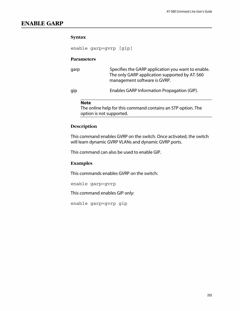
AT-S60 Command Line User’s Guide
ENABLE GARP
Syntax
enable garp=gvrp [gip]
Parameters
garp Specifies the GARP application you want to enable. The only GARP application supported by AT-S60 management software is GVRP.
gip Enables GARP Information Propagation (GIP).
NoteThe online help for this command contains an STP option. The option is not supported.
Description
This command enables GVRP on the switch. Once activated, the switch will learn dynamic GVRP VLANs and dynamic GVRP ports.
This command can also be used to enable GIP.
Examples
This commands enables GVRP on the switch:
enable garp=gvrp
This command enables GIP only:
enable garp=gvrp gip
203
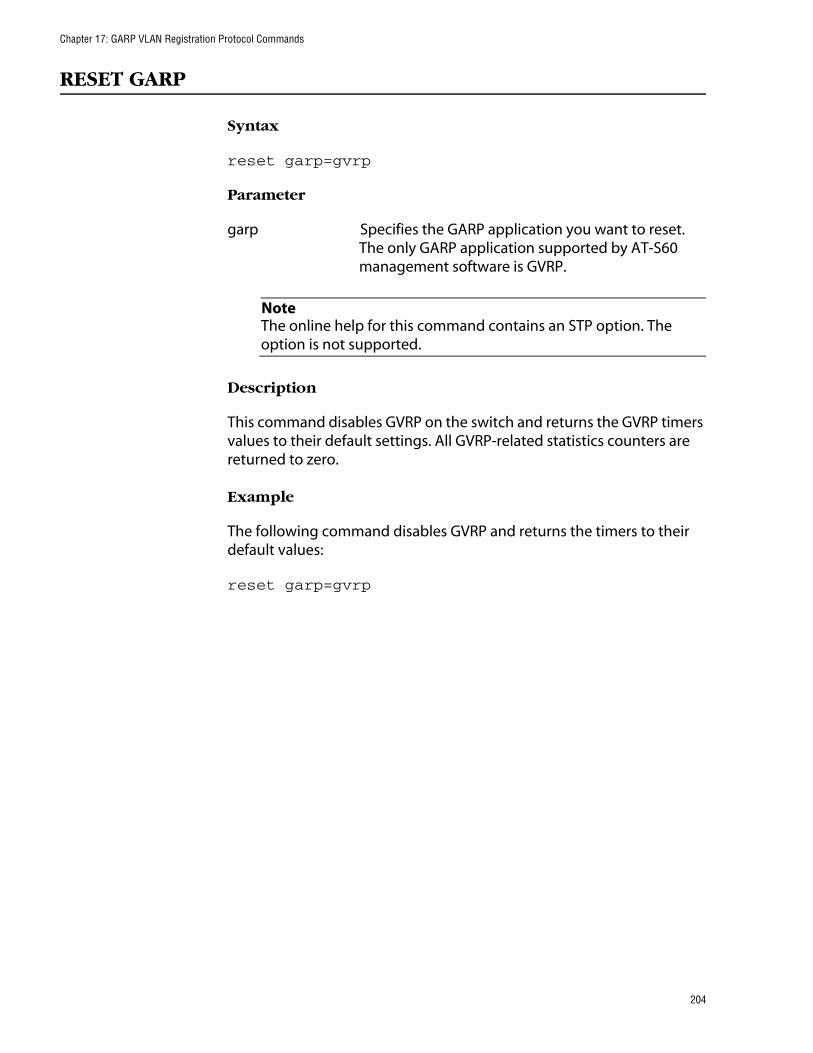
Chapter 17: GARP VLAN Registration Protocol Commands
RESET GARP
Syntax
reset garp=gvrp
Parameter
garp Specifies the GARP application you want to reset. The only GARP application supported by AT-S60 management software is GVRP.
NoteThe online help for this command contains an STP option. The option is not supported.
Description
This command disables GVRP on the switch and returns the GVRP timers values to their default settings. All GVRP-related statistics counters are returned to zero.
Example
The following command disables GVRP and returns the timers to their default values:
reset garp=gvrp
204

AT-S60 Command Line User’s Guide
SET GARP PORT
Syntax
set garp=gvrp port=port|ALL [mode=normal|none]
Parameters
garp Specifies the GARP application you want to configure. The only GARP application supported by AT-S60 management software is GVRP.
port Specifies the port (that is, slot.port) you want to configure on the switch. You can specify more than one port at a time. (For information on how to enter ports, refer to Specifying Ports on page 17.) To specify all ports on the switch, use ALL.
mode Specifies the GVRP mode of the port. Modes are:
normal The port will participate in GVRP. The port will process GVRP information and transmit PDUs. This is the default.
none The port will not participate in GVRP. The port will not process GVRP information nor transmit PDUs.
NoteThe online help for this command contains an STP option. The option is not supported.
Description
This command sets a port’s GVRP status. If you want a port to learn remote VLANs and transmit PDUs, set its mode to Normal. If you do not want a port to participate in GVRP, set its mode to None.
Examples
The following command instructs ports 1 to 4 on the line card in slot 3 to not participate in GVRP:
set garp=gvrp port=3.1-4 mode=none
205

Chapter 17: GARP VLAN Registration Protocol Commands
The following command activates GVRP on port 3 on the line card in slot 12:
set garp=gvrp port=12.3 mode=normal
206

AT-S60 Command Line User’s Guide
SET GARP TIMER
Syntax
set garp=gvrp timer [default] [jointime=integer] [leavetime=integer] [leavealltime=integer]
Parameters
garp Specifies the GARP application you want to configure. The only GARP application supported by AT-S60 management software is GVRP.
default Returns the GARP timers to their default settings.
jointime Specifies the Join Timer in centi seconds, which are one hundredths of a second. The default is 20 centi seconds.
If you change this timer, it must be in relation to the GVRP Leave Timer according to the following equation:
Join Timer <= (2 x (GVRP Leave Timer))
leavetimer Specifies the LeaveTimer in centi seconds, which are one hundredths of a second. The default is 60 centi seconds.
leavealltime Specifies the LeaveAllTimer in centi seconds. The default is 1000 centi seconds.
NoteThe online help for this command contains an STP option. The option is not supported.
Description
This command sets the GARP timers.
NoteThe settings for these timers must be the same on all GVRP-active network devices.
207

Chapter 17: GARP VLAN Registration Protocol Commands
Examples
The following command sets the Join Period timer to 0.1 second, Leave Period timer to 0.35 seconds, and the LeaveAllPeriod timer to 11 seconds for all GVRP applications:
set garp=gvrp timer jointime=10 leavetime=35 leavealltime=1100
The following command sets the timers to their default values:
set garp=gvrp timer default
208

AT-S60 Command Line User’s Guide
SHOW GARP
Syntax
show garp=gvrp
Parameter
garp Specifies the GARP application you want to display. The only GARP application supported by AT-S60 management software is GVRP.
NoteThe online help for this command contains an STP option. The option is not supported.
Description
This command displays current values for the following GARP application parameters:
❑ GARP application protocol
❑ GVRP status
❑ GVRP GIP status
❑ GVRP Join Time
❑ GVRP Leave Time
❑ GVRP Leaveall Time
❑ Port information
❑ Mode
Example
The following command displays GVRP information:
show garp
209

Chapter 17: GARP VLAN Registration Protocol Commands
SHOW GARP COUNTER
Syntax
show garp=gvrp counter
Parameter
garp Specifies the GARP application you want to display. The only GARP application supported by AT-S60 management software is GVRP.
NoteThe online help for this command contains an STP option. The option is not supported.
Description
This command displays the current values for the following GARP packet and message counters:
❑ GARP application
❑ Receive: Total GARP Packets
❑ Transmit: Total GARP Packets
❑ Receive: Invalid GARP Packets
❑ Receive Discarded: GARP Disabled
❑ Receive DIscarded: Port Not Listening
❑ Transmit Discarded: Port Not Sending
❑ Receive Discarded: Invalid Port
❑ Receive Discarded: Invalid Protocol
❑ Receive Discarded: Invalid Format
❑ Receive Discarded: Database Full
❑ Receive GARP Messages: LeaveAll
❑ Transmit GARP Messages: LeaveAll
❑ Receive GARP Messages: JoinEmpty
❑ Transmit GARP Messages: JoinEmpty
210

AT-S60 Command Line User’s Guide
❑ Receive GARP Messages: JoinIn
❑ Transmit GARP Messages: JoinIn
❑ Receive GARP Messages: LeaveEmpty
❑ Transmit GARP Messages: LeaveEmpty
❑ Receive GARP Messages: LeaveIn
❑ Transmit GARP Messages: LeaveIn
❑ Receive GARP Messages: Empty
❑ Transmit GARP Messages: Empty
❑ Receive GARP Messages: Bad Message
❑ Receive GARP Messages: Bad Attribute
Example
The following command displays information for all GARP application counters:
show garp=gvrp counter
211

Chapter 17: GARP VLAN Registration Protocol Commands
SHOW GARP DATABASE
Syntax
show garp=gvrp database
Parameters
garp Specifies the GARP application you want to display. The only GARP application supported by AT-S60 management software is GVRP.
NoteThe online help for this command contains an STP option. The option is not supported.
Description
This command displays the following parameters for the internal database for the GARP application. Each attribute is represented by a GID index within the GARP application.
❑ GARP Application
❑ GID Index
❑ Attribute
❑ Used
Example
The following command displays the database for all GARP applications:
show garp=gvrp database
212

AT-S60 Command Line User’s Guide
SHOW GARP GIP
Syntax
show garp=gvrp gip
Parameter
garp Specifies the GARP application you want to display. The only GARP application supported by AT-S60 management software is GVRP.
NoteThe online help for this command contains an STP option. The option is not supported.
Description
This command displays the following parameters for the GIP-connected ring for the GARP application:
❑ GARP Application
❑ GIP contact
❑ STP ID
Example
The following command displays the GIP-connected ring for all GARP applications:
show garp=gvrp gip
213

Chapter 17: GARP VLAN Registration Protocol Commands
SHOW GARP MACHINE
Syntax
show garp=gvrp machine
Parameter
garp Specifies the GARP application you want to display. The only GARP application supported by AT-S60 management software is GVRP.
NoteThe online help for this command contains an STP option. The option is not supported.
Description
This command displays the following parameters for the GID state machines for the GARP application. The output is shown on a per-GID index basis; each attribute is represented by a GID index within the GARP application.
❑ VLAN
❑ Port
❑ App
❑ Reg
Example
The following command displays GID state machines for all GARP applications:
show garp=gvrp machine
214

Chapter 18
MAC Address Table Commands
This chapter contains the following commands:
❑ ADD SWITCH FDB on page 216
❑ DELETE SWITCH FDB on page 218
❑ SET SWITCH AGINGTIMER on page 219
❑ SHOW SWITCH FDB on page 220
NoteRemember to save your changes with the SAVE CONFIGURATION command.
NoteRefer to the AT-S60 Management Software User’s Guide for background information on the MAC address table.
215

Chapter 18: MAC Address Table Commands
ADD SWITCH FDB
Syntax
add switch fdb macaddress=macaddress port=port vlan=name|vid
Parameters
macaddress Specifies the static unicast or multicast address added to the switch’s MAC address table. The address can be entered in either of the following formats:
xxxxxxxxxxxx or xx:xx:xx:xx:xx:xx
port Specifies the port to which the MAC address is assigned. You can specify only one port if you are adding a unicast address. You can specify more than one port if you are entering a multicast address.
vlan Specifies the VLAN to which the node designated by the MAC address is a member. You can identify the VLAN by name or VID.
Description
This command adds static unicast and multicast MAC addresses to the switch’s MAC address table. A MAC address added with this command is never timed out from the MAC address table, even when the end node or, in the case of a multicast address, the multicast application is inactive.
If you are entering a static multicast address, the address must be assigned to the port when the multicast application is located and to the ports where the host nodes are connected. Assigning the address only to the port where the multicast application is located will result in the failure of the multicast packets to be properly forwarded to the host nodes.
Examples
The following command adds the static MAC address 00:A0:D2:18:1A:11 to Port 7 in Slot 6. It assumes the node that belongs to the MAC address is a member of the Default_VLAN, which has a VID of 1:
add switch fdb macaddress=00A0D2181A11 port=6.7 vlan=1
216

AT-S60 Command Line User’s Guide
The following command adds the multicast MAC address 01:00:51:00:00 10 to Port 1-5 in Slot 6. The ports belongs to the Engineering VLAN:
add switch fdb macaddress=010051000010 port=6.1-5 vlan=Engineering
217

Chapter 18: MAC Address Table Commands
DELETE SWITCH FDB
Syntax
delete switch fdb macaddress=macaddress|dynamic [vlan=name|vid]
Parameters
macaddress Specifies the dynamic or static unicast or multicast MAC address to delete from the MAC address table. The address can be entered in either of the following formats:
xxxxxxxxxxxx or xx:xx:xx:xx:xx:xx
To delete all dynamic addresses from the table, specify DYNAMIC as the address.
vlan Specifies the VLAN containing the ports where the address was learned or assigned. The VLAN can be specified by name or VID. You must specify a VLAN if you are deleting a specific dynamic or static address.
Description
This command deletes dynamic and static unicast and multicast addresses from the switch’s MAC address table.
Examples
The following command deletes the static MAC address 00:A0:D2:18:1A:11 from the table. The port where the address was learned or assigned is part of the Default_VLAN, which has a VID of 1:
delete switch fdb macaddress=00A0D2181A11 vlan=1
The following command deletes the MAC address 00:A0:C1:11:22:44 from the table. The port where the address was learned or assigned is part of the Sales VLAN:
delete switch fdb macaddress=00a0c1112244 vlan=sales
The following command deletes all dynamic addresses from the table:
delete switch fdb macaddress=dynamic
218

AT-S60 Command Line User’s Guide
SET SWITCH AGINGTIMER
Syntax
set switch agingtimer=value
Parameter
agingtimer Specifies the aging timer for the MAC address table. The value is in seconds. The range is 1 to 512. The default is 300 seconds (5 minutes).
Description
The switch uses the aging timer to delete inactive dynamic MAC addresses from the MAC address table. When the switch detects that no packets have been sent to or received from a particular MAC address in the table after the period specified by the aging time, the switch deletes the address. This prevents the table from becoming full of addresses of nodes that are no longer active.
To view the current setting for the MAC address aging timer, use the SHOW SWITCH command.
Example
The following command sets the aging timer to 120 seconds (2 minutes):
set switch agingtimer=120
219

Chapter 18: MAC Address Table Commands
SHOW SWITCH FDB
Syntax
show switch fdb [address=macaddress] [port=port] [status=static|dynamic|multicast] [vlan=name|VID]
Parameters
address Specifies a MAC address. Use this parameter to determine the port on the switch on which a particular MAC address was learned (dynamic) or assigned (static). The address can be entered in either of the following formats:
xxxxxxxxxxxx or xx:xx:xx:xx:xx:xx
port Specifies a port on the switch. Use this parameter to view all addresses learned on a particular port. You can specify more than one port.
status Specifies the type of MAC addresses you want to view. Choices are static, dynamic, and multicast.
vlan Specifies a VLAN. Use this parameter to view the MAC addresses learned or assigned to the ports of a particular VLAN on the switch. The VLAN can be identified by name or VID.
NoteYou can specify more than one parameter at a time with this command.
Description
This command displays the MAC addresses learned or assigned to the ports on the switch.
Examples
The following command displays all MAC addresses in the switch’s MAC address table:
show switch fdb
The following command displays just the multicast addresses:
show switch fdb status=multicast
220

AT-S60 Command Line User’s Guide
The following command displays the port number on which the MAC address 00:A0:D2:18:1A:11 was learned (dynamic) or added (static):
show switch fdb address=00A0D2181A11
The following command displays the MAC addresses learned on Port 2 on the line card in Slot 6:
show switch fdb port=6.2
The following command displays the MAC addresses learned on the ports in the Sales VLAN:
show switch fdb vlan=sales
The following command displays the static MAC addresses on Port 7 on the line card in Slot 2:
show switch fdb port=2.7 status=static
221

Chapter 19
IGMP Snooping Commands
This chapter contains the following commands:
❑ SET IP IGMP on page 223
❑ SHOW IP IGMP on page 225
NoteRemember to use the SAVE CONFIGURATION command to save your changes on the switch.
NoteRefer to the AT-S60 Management Software User’s Guide for background information on IGMP Snooping.
222

AT-S60 Command Line User’s Guide
SET IP IGMP
Syntax
set ip igmp [snoopingstatus=enabled|disabled] [hoststatus=singlehost|multihost] [timeout=integer] [numbermulticastgroups=integer] [routerport=port|auto|none]
Parameters
snoopingstatus Activates and deactivates IGMP snooping on the switch. Possible settings are:
enabled Activates IGMP snooping.
disabled Deactivates IGMP snooping. This is the default setting
hoststatus Specifies the IGMP host node topology. Options are:
singlehost Activates the Single-Host/Port setting, which is appropriate when there is only one host node connected to a port on the switch. This is the default setting.
multihost Activates the Multi-Host setting, which is appropriate if there is more than one host node connected to a switch port.
timeout Specifies the time period, in seconds, used by the switch in determining inactive host nodes. An inactive host node is a node that has not sent an IGMP report during the specified time interval. The range is 1 to 86,400 seconds (24 hours). The default is 260 seconds.
223

Chapter 19: IGMP Snooping Commands
numbermulticastgroups Specifies the maximum number of multicast addresses the switch learns. This parameter is useful with networks that contain a large number of multicast groups. You can use the parameter to prevent the switch’s MAC address table from filling up with multicast addresses, leaving no room for dynamic or static MAC addresses. The range is 1 to 256 addresses. The default is 64 addresses.
routerport Specifies the ports on the switch connected to a multicast router. Options are:
port Specifies the router ports manually.
auto Activates auto-detect, where the switch automatically determines the ports with multicast routers.
none None sets the mode to manual without any router ports specifies.
Description
This command configures the IGMP snooping parameters.
Example
The following command activates IGMP snooping, sets the IGMP topology to Multi-Host, and sets the timeout value to 120 seconds:
set ip igmp snoopingstatus=enabled hoststatus=multihost timeout=120
224

AT-S60 Command Line User’s Guide
SHOW IP IGMP
Syntax
show ip igmp [hostlist] [routerlist]
Parameters
hostlist Displays a list of the multicast groups learned by the switch, as well as the ports on the switch that are connected to host nodes.
routerlist Displays the ports on the switch that are connected to multicast routers.
Description
This command displays the following IGMP parameters:
❑ IGMP snooping status
❑ Multicast host topology
❑ Host/router timeout interval
❑ Maximum multicast groups
❑ Multicast router ports
NoteFor instructions on how to set the IGMP parameters, refer to SET IP IGMP on page 223.
Examples
The following command displays the current IGMP parameter settings:
show ip igmp
The following command displays a list of host nodes:
show ip igmp hostlist
225
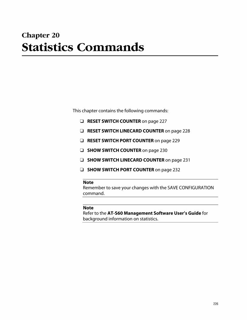
Chapter 20
Statistics Commands
This chapter contains the following commands:
❑ RESET SWITCH COUNTER on page 227
❑ RESET SWITCH LINECARD COUNTER on page 228
❑ RESET SWITCH PORT COUNTER on page 229
❑ SHOW SWITCH COUNTER on page 230
❑ SHOW SWITCH LINECARD COUNTER on page 231
❑ SHOW SWITCH PORT COUNTER on page 232
NoteRemember to save your changes with the SAVE CONFIGURATION command.
NoteRefer to the AT-S60 Management Software User’s Guide for background information on statistics.
226

AT-S60 Command Line User’s Guide
RESET SWITCH COUNTER
Syntax
reset switch counter
Parameters
None.
Description
This command returns all statistic counters on the switch to zero.
Example
The following command resets the statistic counters:
reset switch counter
227
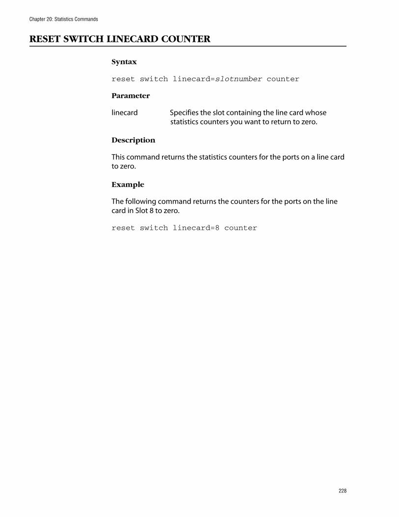
Chapter 20: Statistics Commands
RESET SWITCH LINECARD COUNTER
Syntax
reset switch linecard=slotnumber counter
Parameter
linecard Specifies the slot containing the line card whose statistics counters you want to return to zero.
Description
This command returns the statistics counters for the ports on a line card to zero.
Example
The following command returns the counters for the ports on the line card in Slot 8 to zero.
reset switch linecard=8 counter
228

AT-S60 Command Line User’s Guide
RESET SWITCH PORT COUNTER
Syntax
reset switch port=port|all counter
Parameter
port Specifies the port whose statistics counter you want to return to zero. You can specify more than one port at a time.
Description
This command returns the statistics counter for a port to zero.
Example
The following command returns the counters on Ports 4 and 5 on the line card in Slot 8 to zero.
reset switch port=8.4,5 counter
229

Chapter 20: Statistics Commands
SHOW SWITCH COUNTER
Syntax
show switch counter
Parameters
None.
Description
This command displays switch operating statistics, such as the number of packets received and transmitted, and the number of CRC errors. For a list of and definitions for the statistics, refer to the AT-S60 Management Software User’s Guide.
Example
The following command displays switch operating statistics:
show switch counter
230

AT-S60 Command Line User’s Guide
SHOW SWITCH LINECARD COUNTER
Syntax
show switch linecard=slotnumber counter
Parameter
linecard Specifies the slot containing the line card whose statistics you want to view.
Description
This command displays the operating statistics for all the ports on a line card. Examples of the statistics include the number of packets transmitted and received, and the number of CRC errors. For a list of and definitions for the statistics, refer to the AT-S60 Management Software User’s Guide.
Examples
The following command displays the operating statistics for the ports on the line card in Slot 7:
show switch linecard=7 counter
231

Chapter 20: Statistics Commands
SHOW SWITCH PORT COUNTER
Syntax
show switch port=port counter
Parameter
port Specifies the port whose statistics you want to view. You can view more than one port at a time. To view all ports, do not specify a port.
Description
This command displays the operating statistics for a port on the switch. Examples of the statistics include the number of packets transmitted and received, and the number of CRC errors. For a list of and definitions for the statistics, refer to the AT-S60 Management Software User’s Guide.
Examples
The following command displays the operating statistics for Port 4 on the line card in Slot 6:
show switch port=6.4 counter
The following command displays the operating statistics for all ports:
show switch port counter
232

Chapter 21
Web Server Commands
This chapter contains the following commands:
❑ DISABLE HTTP SERVER on page 234
❑ ENABLE HTTP SERVER on page 235
❑ RESET HTTP SERVER on page 236
❑ SET HTTP SERVER on page 237
❑ SHOW HTTP SERVER on page 241
NoteThis chapter lists some encryption commands. The encryption commands only appear in the AT-S60 version 2.0.0 software. Refer to the AT-S60 Management Software User’s Guide for background information on encryption.
NoteRemember to use the SAVE CONFIGURATION command to save your changes.
233

Chapter 21: Web Server Commands
DISABLE HTTP SERVER
Syntax
disable http server
Parameters
None.
Description
This command disables the HTTP server on the switch. When HTTP is disabled, you cannot manage the switch using a web browser management session. To view the current status of the HTTP server, see the command SHOW HTTP SERVER on page 241.
Example
The following command disables the HTTP server:
disable http server
234

AT-S60 Command Line User’s Guide
ENABLE HTTP SERVER
Syntax
enable http server
Parameters
None.
Description
This command activates the HTTP server on the switch. Activating HTTP allows you to manage the switch using a web browser management session. To view the current status of the HTTP server, see the command SHOW HTTP SERVER on page 241.
Example
The following command activates the HTTP server:
enable http server
235

Chapter 21: Web Server Commands
RESET HTTP SERVER
Syntax
reset http server
Parameters
None.
Description
This command resets the HTTP server on the switch to its default values. To view the current status of the HTTP server, see the command SHOW HTTP SERVER on page 241.
Example
The following command resets the HTTP server to its default values:
reset http server
236

AT-S60 Command Line User’s Guide
SET HTTP SERVER
Syntax
set http server [security=enabled|disabled] [sslkey=key-id] [port=port]
Parameters
security Specifies whether or not security is implemented on the switch when it is configured as an HTTP server. Possible settings are:
enabled Specifies that the server accepts only SSL connections using HTTPS.
disabled Specifies that the server accepts only HTTP connections.
sslkey Specifies a private key ID. Required if security is enabled. This key is created through the encryption commands. See CREATE ENCO KEY on page 243. The corresponding certificate must also be created before you specify the key. See CREATE PKI CERTIFICATE on page 252.
port Specifies the TCP port number that the HTTP server will listen on. If you do not specify a value for the port parameter, the following defaults are used:
— When the security parameter is set to enabled (HTTPS), the default port is port 443.
— When the security parameter is set to disabled (HTTP), the default port is port 80.
Description
This command sets the web server configuration as HTTP or HTTPS. Before you configure this command, you must disable the web server using DISABLE HTTP SERVER on page 234. After you have finished configuring this command, enable the web server.
If you set the security parameter to enabled, the server accepts only SSL connections which use HTTPS. If you set the security parameter to disabled, the server accepts only HTTP connections. The default is disabled.
237

Chapter 21: Web Server Commands
Example
The following command disables the HTTP server:
disable http server
The following command configures the switch as an HTTPS server with a key ID of 5:
set http server security=enabled sslkey=5
Creating a Self-Signed
Certificate
This section provides a procedure to configure the switch as a web server using a self-signed certificate. It is followed by an example.
For detailed information about the AT-S60 security features, see Section III: Security Features in the AT-S60 Software Management User’s Guide.
To create self-signed certificate, perform the following procedure. This procedure lists the commands you need to enter and a cross reference to the commands.
1. Set the date and time for the switch. You can do this manually using SET DATE on page 64 and SET TIME on page 66. Or, you can configure the switch to obtain the date and time from an SNTP server using ADD SNTPSERVER IPADDRESS on page 59.
2. Assign a distinguished name to the switch using SET SYSTEM DISTINGUISHEDNAME on page 261.
3. Create an encryption key pair using CREATE ENCO KEY on page 243.
4. Create a self-signed certificate using CREATE PKI CERTIFICATE on page 252.
5. Add the self-signed certificate to the certificate database using ADD PKI CERTIFICATE on page 250.
6. Disable the switch’s web server using DISABLE HTTP SERVER on page 234.
7. Configure the web server using SET HTTP SERVER on page 237.
8. Activate the web server using ENABLE HTTP SERVER on page 235.
238

AT-S60 Command Line User’s Guide
Example of Creating a Self-Signed Certificate
Here is an example of creating a self-signed certificate.
#set date 29-02-2004#set time 10:40:55#set system distinguishedname=”cn=Cleo Starfas ou=Operations o=Arctic Company l=Fairbanks s=Alaska c=us”#create enco key=1 type=rsa length=512 description=serverkey05 format=hex#create pki certifcate=accountingserver14 keypair=1 serialnumber=217#add pki certificate=keithscertificate trusted=yes type=ee location=keithscertificate.cer#disable http server#set http server security=enabled sslkeyid=1#enable http server
Creating a CACertificate
This section provides a procedure to configure the switch as a web server with a CA certificate. It is followed by an example.
For detailed information about the AT-S60 security features, see Section III: Security Features in the AT-S60 Software Management User’s Guide.
To create a CA certificate, perform the following procedure. This procedure lists the commands you need to enter and a cross reference to the commands.
1. Set the date and time for the switch. You can do this manually using SET DATE on page 64 and SET TIME on page 66. Or, you can configure the switch to obtain the date and time from an SNTP server using ADD SNTPSERVER IPADDRESS on page 59.
2. Assign a distinguished name to the switch using SET SYSTEM DISTINGUISHEDNAME on page 261.
3. Create an encryption key pair using CREATE ENCO KEY on page 243.
4. Create an enrollment request using CREATE PKI ENROLLMENTREQUEST on page 254.
5. Upload the enrollment request from the switch to a management workstation or FTP server with UPLOAD on page 134
6. Submit the enrollment request to a CA. Usually, you would email the enrollment request to a CA.
7. Once you have received a CA certificate, download it into the switch’s file system using LOAD on page 129.
8. Add the CA certificate to the certificate database using ADD PKI CERTIFICATE on page 250.
239

Chapter 21: Web Server Commands
9. Disable the switch’s web server using DISABLE HTTP SERVER on page 234.
10. Configure the web server using SET HTTP SERVER on page 237.
11. Activate the web server using ENABLE HTTP SERVER on page 235.
Example of Creating a CA Certificate
Here is an example of creating a CA certificate.
#set date 15-05-2004#set time 16:34:55#set syst distinguishedname=”cn=Anu ou=Engineering o=Ace l=Christ Church c=nz”#create enco key=2 type=rsa length=512#create enrollmentrequest=verisignrequest keypair=2 serialnumber=317#upload method=tftp destfile=c:\software\anu.cer server=149.36.11.21 file=anu.cer#load method=tftp destfile=c:\software\anu.cer server=149.36.11.21 file=anu.cer#add pki certificate=anu location=anu.cer#disable http server#set http server security=enabled sslkeyid=2#enable http server
240

AT-S60 Command Line User’s Guide
SHOW HTTP SERVER
Syntax
show http server
Parameters
None.
Description
This command displays the following information about the HTTP server on the switch:
❑ Status
❑ SSL security
❑ SSL key ID
❑ Port
❑ Listen port
Example
The following command displays the status of the HTTP server:
show http server
241

Chapter 22
Encryption Commands
This chapter contains the following commands:
❑ CREATE ENCO KEY on page 243
❑ DESTROY ENCO KEY on page 246
❑ SET ENCO KEY on page 247
❑ SHOW ENCO KEY on page 248
NoteThe encryption commands only appear in the AT-S60 version 2.0.0 software. Refer to the AT-S60 Management Software User’s Guide for background information on encryption.
NoteRemember to save your changes with the SAVE CONFIGURATION command.
242
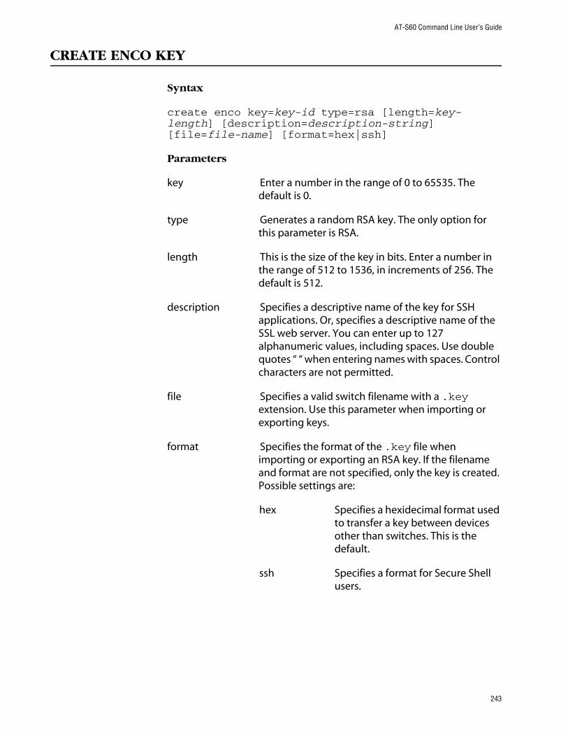
AT-S60 Command Line User’s Guide
CREATE ENCO KEY
Syntax
create enco key=key-id type=rsa [length=key-length] [description=description-string] [file=file-name] [format=hex|ssh]
Parameters
key Enter a number in the range of 0 to 65535. The default is 0.
type Generates a random RSA key. The only option for this parameter is RSA.
length This is the size of the key in bits. Enter a number in the range of 512 to 1536, in increments of 256. The default is 512.
description Specifies a descriptive name of the key for SSH applications. Or, specifies a descriptive name of the SSL web server. You can enter up to 127 alphanumeric values, including spaces. Use double quotes “ “ when entering names with spaces. Control characters are not permitted.
file Specifies a valid switch filename with a .key extension. Use this parameter when importing or exporting keys.
format Specifies the format of the .key file when importing or exporting an RSA key. If the filename and format are not specified, only the key is created. Possible settings are:
hex Specifies a hexidecimal format used to transfer a key between devices other than switches. This is the default.
ssh Specifies a format for Secure Shell users.
243

Chapter 22: Encryption Commands
Description
This command creates an encryption key and stores the key information in the switch’s file system. This command can also be used to import or export RSA keys.
The KEY parameter specifies the identification number for the key.
The TYPE parameter specifies the type of key to be created. The only option is RSA.
The LENGTH parameter specifies the bit length of the key. To configure host and server keys for SSH, there are guidelines regarding the length of the keys. The bit size of the SSH host and server keys must differ by 128 bits. The recommended bit size for a server key is 768 bits. The minimum bits size of a server key is 512 bits. For the host key, the recommended bit size is 1024 bits.
The DESCRIPTION parameter specifies a user-defined description of the web server the key is used to protect.
If the FILE parameter is specified, the RSA key is imported from or exported to the specified file. If the FILE parameter is not specified, then a random RSA key is generated.
The FILE parameter specifies name of a key file. RSA public keys may be imported from or exported to a file in either Secure Shell format or in hexadecimal format. If the file exists but the specified RSA key does not exist, then the RSA key is imported from the file. If the specified RSA key exists but the file does not exist, the RSA key is exported to the file. In addition, the FORMAT parameter must be specified when importing or exporting keys.
The FORMAT parameter specifies the format of the .key file when importing or exporting an RSA key. Specify SSH when you are using the Secure Shell feature. Specify the HEX format when transferring keys between devices. The default is HEX. If FORMAT is specified, the FILE parameter must also be present.
Examples
To create a new certificate with a new key id of 300, the type as RSA, a length of 512 bits, and a description of serverkey17 in HEX format, enter:
create enco key=300 type=rsa length=512 description=serverkey17 format=hex
244

AT-S60 Command Line User’s Guide
NoteIn the above command, you are creating a key id. Therefore, the key id of 300 must not exist before this command is executed.
To import an RSA key from the file RSA.KEY, which is in HEX format, as key 3:
create enco key=3 type=rsa file=rsa.key format=hex
To export an RSA key with an existing key id of 4 in HEX format:
create enco key=4 file=rsaexport.key format=hex
NoteIn the above command, you are exporting an existing RSA. Therefore, the key id of 4 must exist before executing this command.
245

Chapter 22: Encryption Commands
DESTROY ENCO KEY
Syntax
destroy enco key=key-id
Parameter
key A number in the range 0 to 65535. There is no default.
Description
This command destroys the specified encryption key. The memory the key occupied is overwritten to ensure that the key is irretrievable.
The KEY parameter specifies the identification number for the key. A key with the specified identification number must exist.
Example
The following command destroys an encryption key with the key identification number of 4:
destroy enco key=4
246

AT-S60 Command Line User’s Guide
SET ENCO KEY
Syntax
set enco key=key-id [description=description-string]
Parameters
key A number in the range 0 to 65535.
description A character string, 1 to 25 characters in length. Valid characters are any printable character. To add spaces to this parameter spaces, enclosed them in double quotes.
Description
This command changes the user-defined description for a specified key.
The KEY parameter specifies the identification number for the key. The specified encryption key must already exist. See CREATE ENCO KEY on page 243.
The DESCRIPTION parameter specifies a user-defined description of the key, to make it easier to keep track of different keys.
Example
This command specifies the description for key 1:
set enco key=1 description=”switch z key”
247

Chapter 22: Encryption Commands
SHOW ENCO KEY
Syntax
show enco key=key-id
Parameter
key A number in the range of 0 to 65535. There is no default.
Description
This command displays information about a specific encryption key. Of course, the key must already be configured.
Example
This command displays information about a key with a key id of 150:
show enco key=150
248
AT-S60 Command Line User’s Guide
Chapter 23
Public Key Infrastructure (PKI) Commands
This chapter contains the following commands:
❑ ADD PKI CERTIFICATE on page 250
❑ CREATE PKI CERTIFICATE on page 252
❑ CREATE PKI ENROLLMENTREQUEST on page 254
❑ DELETE PKI CERTIFICATE on page 256
❑ PURGE PKI on page 257
❑ SET PKI CERTIFICATE on page 258
❑ SET PKI CERTSTORELIMIT on page 260
❑ SET SYSTEM DISTINGUISHEDNAME on page 261
❑ SHOW PKI on page 262
❑ SHOW PKI CERTIFICATE on page 263
NoteThe Public Key Infrastructure (PKI) feature only appears in the AT-S60 version 2.0.0 software. Refer to the AT-S60 Management Software User’s Guide for background information on Public Key Infrastructure.
NoteRemember to save your changes with the SAVE CONFIGURATION command.
249

Chapter 23: PKI Commands
ADD PKI CERTIFICATE
Syntax
add pki certificate=certificate-name location=file-name [trusted=true|false] [type=ca|ee|self]
Parameters
certificate A character string, 1 to 24 characters in length. Valid characters are any printable characters. If the name contains spaces, it must be enclosed in double quotes. Wildcards are not allowed.
location Specifies the name of the certificate file with the file extension of .cer.
trusted Specifies whether or not the certificate is automatically trusted. Possible settings are:
true Indicates you manually verified the certificate is from a trusted certificate authority (CA).
false Indicates the certificate is from an untrusted CA. This is the default.
type Specifies what type of certificate is being added. Possible settings are:
ca Tags the certificate as a CA certificate.
ee Tags the certificate as belonging to another end entity (EE). This is the default.
self Tags the certificate as a self-signed certificate which is created for use on the switch.
Description
This command adds a certificate, from either a file in the switch’s file system or a trusted authority, to the switch’s certificate database. The ADD PKI CERTIFICATE requires that the file, indicated with the LOCATION parameter, already exists.
250

AT-S60 Command Line User’s Guide
The LOCATION parameter specifies the file name of the certificate. This is the name that is used to retrieve a certificate from the switch’s file system. The local file must be a valid filename with the file extension of.cer. The .cer file must already exist. There are two ways to create this type of file. Either you create a self-signed certificate using the CREATE PKI CERTIFICATE command or you download a CA certificate onto the switch.
The TRUSTED parameter specifies whether or not the certificate is automatically trusted. You must manually verify if a certificate is from a certificate authority that is trusted or untrusted. If you have manually verified a certificate is from a trusted CA, set this parameter to TRUE. Set this parameter to FALSE, if you have manually verified that the certificate is from an untrusted CA. In addition, you can set this parameter to FALSE if you have not yet manually verified the state of the CA. The default is FALSE. Typically, you set self-signed root CA certificates and certificates from a trusted third-party, such as Verisign, as automatically trusted. Check the certificate’s fingerprint and other details using SHOW PKI CERTIFICATE on page 263.
The TYPE parameter specifies what type of certificate is being added. If CA is specified, the switch tags this certificate as a CA certificate. If END ENTITY or EE is specified, the switch tags the certificate to indicate that it belongs to another end entity. If SELF is specified, the switch tags the certificate as a self-signed certificate. The default is ENDENTITY.
Example
The following command loads a trusted certificate, called “bobscertificate,” with a type of End Entity and a filename of bobscertificate.cer:
add pki certificate=bobscertificate trusted=yes type=ee location=bobcertificate.cer
251

Chapter 23: PKI Commands
CREATE PKI CERTIFICATE
Syntax
create pki certificate=certificate-name keypair=key-id serialnumber=serial-number [format=der|pem] [subject=distinguished-name]
Parameters
certificate A character string, 1 to 8 characters in length. Valid characters are uppercase letters (A-Z), lowercase letters (a-z), digits (0-9), the underscore character (“_”), the hyphen character (“-”), any printable characters, and any alphanumeric characters. If the name contains spaces, it must be enclosed in double quotes. Wildcards are not allowed.
keypair A decimal number in the range of 0 to 65535. There is no default. The key must exist. See CREATE ENCO KEY on page 243.
serialnumber A decimal number in the range of 0 to 2147483647. The default is 0.
format Specifies the type of encoding the certificate will use. Possible settings are:
der Specifies binary format which cannot be displayed. This is the default.
pem Specifies an ASCII-encoded format that allows the certificate to be displayed once it is generated.
subject Specifies a distinguished name, as described in SET SYSTEM DISTINGUISHEDNAME on page 261. This optional parameter is used to override the existing switch DN setting.
252

AT-S60 Command Line User’s Guide
Description
This command creates a self-signed certificate using an ENCO private RSA key and the switch’s distinguished name. The switch’s distinguished name, set with the SET SYSTEM DISTINGUISHEDNAME on page 261, is inserted in the issuer field of the certificate. This certificate is suitable for use with an SSL-enabled HTTP server or where third party trust is not required.
NoteBefore executing this command, set the system time correctly. See SET TIME on page 66.
The KEYPAIR parameter specifies the encryption key-id of the private RSA key that will be used to sign the certificate. This key must already be configured. See CREATE ENCO KEY on page 243.
The SERIALNUMBER parameter specifies the number to be inserted into the serial number field of the certificate. Usually, this parameter is set to 0.
The FORMAT parameter specifies the type of encoding the certificate will use. The DER encoding is binary and so it cannot be displayed in a text editor once it has been generated. The default is DER. The PEM value is ASCII-encoded and allows the certificate to be displayed in a text editor once it has been generated.
The SUBJECT parameter specifies the distinguished name inserted in the subject field of the certificate for this certificate only. If this parameter is not specified, the system distinguished name is used. See SET SYSTEM DISTINGUISHEDNAME on page 261.
NoteThe certificate is valid for two years from the current date.
Example
The following command creates a self-signed certificate in a file called mycert.cer:
create pki certificate=mycert keypair=1 serialnumber=1234
253

Chapter 23: PKI Commands
CREATE PKI ENROLLMENTREQUEST
Syntax
create pki enrollmentrequest=request-name keypair=key-id [format=der|pem] [type=pkcs10]
Parameters
enrollmentrequest A character string, 1 to 8 characters in length. Valid characters are any printable characters. If the name contains spaces, it must be enclosed in double quotes. Wildcards are not accepted.
keypair A decimal number in the range 0 to 65535. There is no default.
format Specifies the type of encoding the certificate will use. Possible settings are:
der Specifies binary format which cannot be displayed in a text editor. This is the default.
pem Specifies an ASCII-encoded format that allows the certificate to be displayed in a text editor once it is generated.
type Formats the request according to PKCS #10.
Description
This command creates a certificate enrollment request. This operation is required when you first create a new key pair and want to get it signed by a CA. The enrollment request must be transmitted to the CA manually. Usually, this is done through email.
The ENROLLMENTREQUEST parameter specifies a name of the enrollment request. This value is used to create the requested file in the format “filename.csr.” This is a file that has to be taken out of the file system with the UPLOAD command and manually sent to the CA. See UPLOAD on page 134.
The KEYPAIR parameter specifies the encryption key of the certificate. This value must be defined with the CREATE ENCO KEY command. See CREATE ENCO KEY on page 243.
254

AT-S60 Command Line User’s Guide
The FORMAT parameter specifies the type of encoding format for the request. The DER value specifies that the enrollment request is written to the binary file which cannot be displayed in a text editor. The default is DER. The PEM value specifies that the enrollment request is encoded using the “Privacy Enhanced Mail” format. The PEM encoding format can be displayed in a text editor once it has been generated.
The TYPE parameter specifies the type of request. The only option is PKCS10.
Example
The following command creates an enrollment request and a file named “mycert.csr” with a keypair of 150:
create pkienrollmentrequest=mycert keypair=150
255

Chapter 23: PKI Commands
DELETE PKI CERTIFICATE
Syntax
delete pki certificate=certificate-name
Parameter
certificate A character string, 1 to 24 characters in length. Valid characters are any printable characters. If the name contains spaces, it must be enclosed in double quotes. Wildcards are not allowed.
Description
This command deletes one or all of the certificates stored in the switch’s certificate database. The CERTIFICATE parameter specifies the name of the certificate to be deleted.
CautionIf you do not specify a certificate name, all the certificates on the switch are deleted.
Example
The following command deletes the certificate named “bobs_old_certificate”:
delete pki certificate=bobs_old_certificate
The following command deletes all the certificates on the switch:
delete pki
256
AT-S60 Command Line User’s Guide
PURGE PKI
Syntax
purge pki
Parameter
None.
Description
This command deletes any certificates saved on the switch and resets the PKI parameters to their default values. The following parameters are affected:
❑ Maximum number of certificates is reset to 256.
Example
The following command deletes certificates and resets the PKI parameters to their default values:
purge pki
257

Chapter 23: PKI Commands
SET PKI CERTIFICATE
Syntax
set pki certificate=certificate-name [trusted=true|false] [type=ca|ee|self]
Parameter
certificate A character string, 1 to 24 characters in length. Valid characters are any printable characters. If the name contains spaces, it must be enclosed in double quotes. Wildcards are not allowed.
trusted Specifies whether or not the certificate is automatically trusted. Possible settings are:
true Indicates you manually verified the certificate is from a trusted certificate authority (CA).
false Indicates the certificate is from an untrusted CA. This is the default.
type Specifies what type of certificate is being added. Possible settings are:
ca Tags the certificate as a CA certificate.
ee Tags the certificate as belonging to another end entity (EE). This is the default.
self Tags the certificate as created for use on the switch.
Description
This command allows you to update the configuration of a certificate by modifying the trust and type. To use this command, the certificate must exist in the certificate database. To list the current certificates in the certificate database, see SHOW PKI CERTIFICATE on page 263.
258

AT-S60 Command Line User’s Guide
Example
The following command configures a trusted certificate with a type of self:
set pki certificate=giftcertificate trusted=true type=self
259

Chapter 23: PKI Commands
SET PKI CERTSTORELIMIT
Syntax
set pki certstorelimit=certificate-limit
Parameter
certstorelimit A number between 12 and 256. The default is 256.
Description
This command sets the maximum number of certificates which can be stored in the switch’s certificate database. The default is 256.
Example
This command sets the certificate storage limit to 100:
set pki certstorelimit=100
260
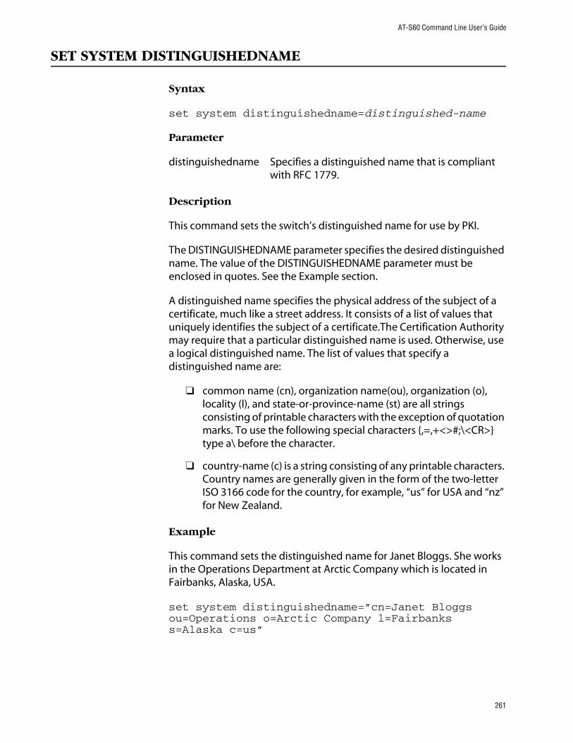
AT-S60 Command Line User’s Guide
SET SYSTEM DISTINGUISHEDNAME
Syntax
set system distinguishedname=distinguished-name
Parameter
distinguishedname Specifies a distinguished name that is compliant with RFC 1779.
Description
This command sets the switch’s distinguished name for use by PKI.
The DISTINGUISHEDNAME parameter specifies the desired distinguished name. The value of the DISTINGUISHEDNAME parameter must be enclosed in quotes. See the Example section.
A distinguished name specifies the physical address of the subject of a certificate, much like a street address. It consists of a list of values that uniquely identifies the subject of a certificate.The Certification Authority may require that a particular distinguished name is used. Otherwise, use a logical distinguished name. The list of values that specify a distinguished name are:
❑ common name (cn), organization name(ou), organization (o), locality (l), and state-or-province-name (st) are all strings consisting of printable characters with the exception of quotation marks. To use the following special characters {,=,+<>#;\<CR>} type a\ before the character.
❑ country-name (c) is a string consisting of any printable characters. Country names are generally given in the form of the two-letter ISO 3166 code for the country, for example, “us” for USA and “nz” for New Zealand.
Example
This command sets the distinguished name for Janet Bloggs. She works in the Operations Department at Arctic Company which is located in Fairbanks, Alaska, USA.
set system distinguishedname=”cn=Janet Bloggs ou=Operations o=Arctic Company l=Fairbanks s=Alaska c=us”
261

Chapter 23: PKI Commands
SHOW PKI
Syntax
show pki
Parameters
None.
Description
This command displays the following information about the PKI module:
❑ Maximum # of certificates
Example
This command shows PKI module information:
show pki
262

AT-S60 Command Line User’s Guide
SHOW PKI CERTIFICATE
Syntax
show pki certificate=certificate-name
Parameter
certificate A character string, 1 to 24 characters in length. Valid characters are any printable characters. If the name contains spaces, it must be enclosed in double quotes. Wildcards are not allowed.
Description
This command displays information about a certificate or all certificates in the switch’s certificate database.
Example
This command displays information about a PKI certificate named “bobs_certificate”:
show pki certificate=bobs_certificate
263
Chapter 24
Secure Sockets Layer (SSL) Commands
This chapter contains the following command:
❑ SET SSL on page 265
❑ SHOW SSL on page 266
NoteThe SSL feature only appears in the AT-S60 version 2.0.0 software. Refer to the AT-S60 Management Software User’s Guide for background information on SSL.
NoteRemember to save your changes with the SAVE CONFIGURATION command.
264

AT-S60 Command Line User’s Guide
SET SSL
Syntax
set ssl cachetimeout=timeout value in seconds [maxsessions=maximum-sessions]
Parameters
cachetimeout A decimal number in the range of 1 to 600. The default is 1.
maxsessions A decimal number in the range of 0 to 100.
Description
This command sets the parameters required to configure SSL.
The CACHETIMEOUT parameter determines the maximum amount of time that a session is retained in the cache. The cache stores information about closed connections so they can be resumed quickly. The default is 300 seconds.
The MAXSESSIONS parameter specifies the maximum number of sessions that are allowed in the session resumption cache. The default is 2000 sessions.
Example
The following command sets the session resumption cache to 180 seconds:
set ssl cachetimeout=180
265

Chapter 24: SSL Commands
SHOW SSL
Syntax
show ssl
Parameters
None.
Description
This command displays current values for the following SSL parameters:
❑ Version
❑ Ciphers Available
❑ Maximum Number of Sessions
❑ Cache Timeout
Example
The following command displays the SSL parameters.
show ssl
266

Chapter 25
Secure Shell (SSH) Commands
This chapter contains the following commands:
❑ DISABLE SSH SERVER on page 268
❑ ENABLE SSH SERVER on page 269
❑ SET SSH SERVER on page 270
❑ SHOW SSH on page 273
NoteThe SSL feature only appears in the AT-S60 version 2.0.0 software. Refer to the AT-S60 Management Software User’s Guide for background information on SSH.
NoteRemember to save your changes with the SAVE CONFIGURATION command.
267
Chapter 25: SSH Commands
DISABLE SSH SERVER
Syntax
disable ssh server
Parameters
None.
Description
This command disables the Secure Shell server. When the Secure Shell server is disabled, connections from Secure Shell clients are not accepted.
By default, the Secure Shell server is disabled.
Example
The following command disables the Secure Shell server:
disable ssh server
268

AT-S60 Command Line User’s Guide
ENABLE SSH SERVER
Syntax
enable ssh server hostkey=key-id serverkey=key-id [expirytime=hours] [logintimeout=seconds]
Parameters
hostkey A decimal key ID.
serverkey A decimal key ID.
expirytime The time in hours.
logintimeout The time in seconds.
Description
This command enables the Secure Shell server. When the Secure Shell server is enabled, connections from Secure Shell clients are accepted.
The HOSTKEY parameter specifies the key that is to be used for the switch host key. The specified key must exist.
The SERVERKEY parameter specifies the key that is to be used for the Secure Shell server key. The specified key must exist.
The EXPIRYTIME parameter specifies the time, in hours, after which the Secure Shell server key will expire and will be regenerated. If 0 is specified the key does not expire. The range is 0 to 5 and the default is 0.
The LOGINTIMEOUT parameter specifies the length of time the server waits before disconnecting an un-authenticated client. The range is 60 to 600 and the default is 180.
By default the Secure Shell server is disabled.
NoteBefore you enable SSH, disable the Telnet management session. Otherwise, the security provided by SSH is not active. See DISABLE TELNET on page 30.
Example
The following command enables the Secure Shell server:
enable ssh server hostkey=0 serverkey=1
269

Chapter 25: SSH Commands
SET SSH SERVER
Syntax
set ssh server hostkey=key-id serverkey=key-id [expirytime=hours] [logintimeout=seconds]
Parameters
hostkey A decimal key ID.
serverkey A decimal key ID.
expirytime The time in hours.
logintimeout The time in seconds.
Description
This command modifies the configuration of the Secure Shell server.
The HOSTKEY parameter specifies the key that is used for the switch host key. The specified key must exist.
The SERVERKEY parameter specifies the key that is used for the Secure Shell server key. The specified key must exist.
The EXPIRYTIME parameter specifies the time, in hours, after which the Secure Shell server key will expire and will be regenerated. If 0 is specified the key does not expire. The default is 0.
The LOGINTIMEOUT parameter specifies the length of time the server waits before disconnecting an un-authenticated client. The default is 180 seconds (3 minutes).
By default, the Secure Shell server is disabled. Secure Shell sessions may be initiated from the switch to another host, but inbound connections will not be accepted.
Example
The following command sets the Secure Shell server key expiry time to 1 hour:
set ssh server expirytime=1
270
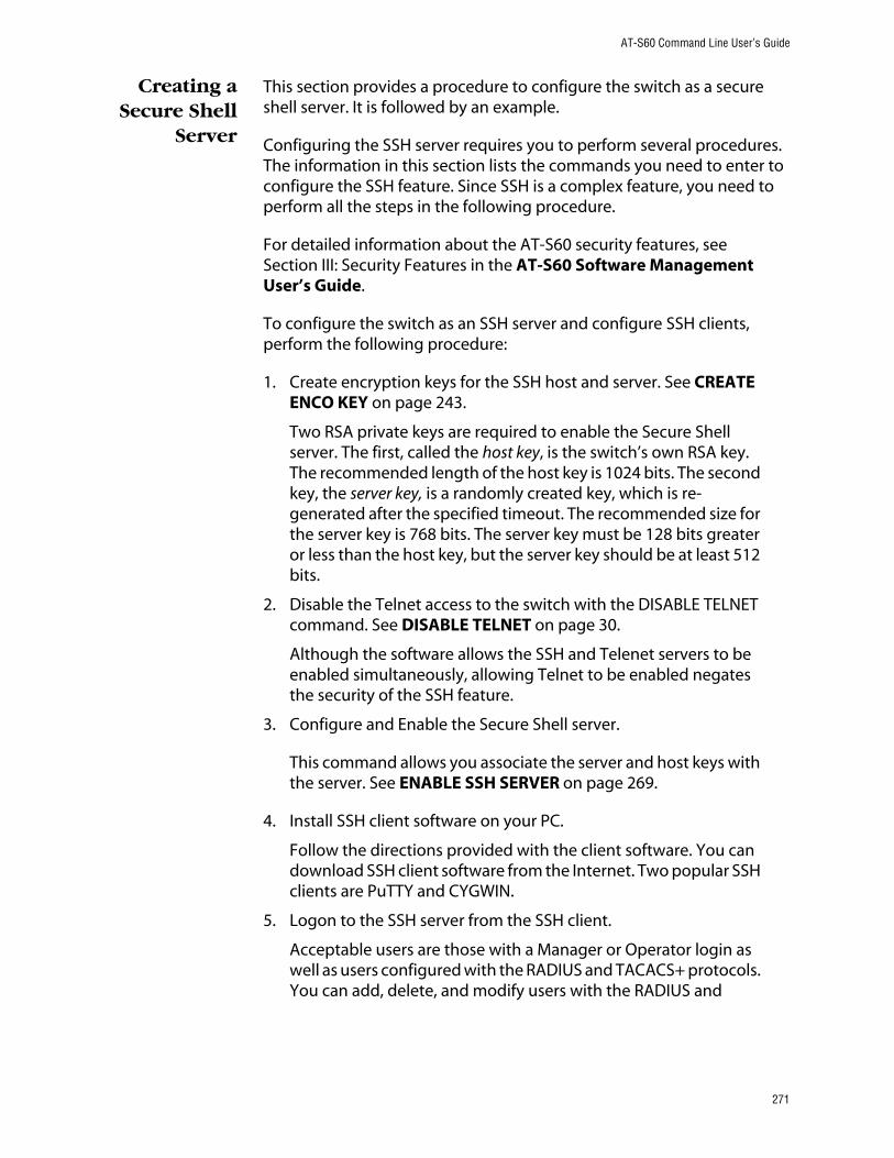
AT-S60 Command Line User’s Guide
Creating aSecure Shell
Server
This section provides a procedure to configure the switch as a secure shell server. It is followed by an example.
Configuring the SSH server requires you to perform several procedures. The information in this section lists the commands you need to enter to configure the SSH feature. Since SSH is a complex feature, you need to perform all the steps in the following procedure.
For detailed information about the AT-S60 security features, see Section III: Security Features in the AT-S60 Software Management User’s Guide.
To configure the switch as an SSH server and configure SSH clients, perform the following procedure:
1. Create encryption keys for the SSH host and server. See CREATE ENCO KEY on page 243.
Two RSA private keys are required to enable the Secure Shell server. The first, called the host key, is the switch’s own RSA key. The recommended length of the host key is 1024 bits. The second key, the server key, is a randomly created key, which is re-generated after the specified timeout. The recommended size for the server key is 768 bits. The server key must be 128 bits greater or less than the host key, but the server key should be at least 512 bits.
2. Disable the Telnet access to the switch with the DISABLE TELNET command. See DISABLE TELNET on page 30.
Although the software allows the SSH and Telenet servers to be enabled simultaneously, allowing Telnet to be enabled negates the security of the SSH feature.
3. Configure and Enable the Secure Shell server.
This command allows you associate the server and host keys with the server. See ENABLE SSH SERVER on page 269.
4. Install SSH client software on your PC.
Follow the directions provided with the client software. You can download SSH client software from the Internet. Two popular SSH clients are PuTTY and CYGWIN.
5. Logon to the SSH server from the SSH client.
Acceptable users are those with a Manager or Operator login as well as users configured with the RADIUS and TACACS+ protocols. You can add, delete, and modify users with the RADIUS and
271

Chapter 25: SSH Commands
TACACS+ feature. For information about how to configure RADIUS and TACACS+, see TACACS+ and RADIUS Commands on page 284.
Example
Here is an example of creating a SSH web server:
#create enco key=1 type=rsa length=1024 description=”host key” format=ssh#create enco key=2 type=rsa length=768 description=”server key” format=ssh#disable telnet#enable ssh server hostkey=1 serverkey=2
272

AT-S60 Command Line User’s Guide
SHOW SSH
Syntax
show ssh
Parameters
None.
Description
This command displays current values for the following SHOW SSH configuration:
❑ Versions supported
❑ Server Status
❑ Server Port
❑ Host Key ID
❑ Host Key Bits (size of host key in bits)
❑ Server Key ID
❑ Server Key Bits (size of server key in bits)
❑ Server Key Expiry (hours)
❑ Login Timeout (seconds)
❑ Authentication Available
❑ Ciphers Available
❑ MACs Available
❑ Data Compression
Example
The following command displays the configuration of the Secure Shell server:
show ssh
273

Chapter 26
802.1x Port-Based Access Control Commands
This chapter contains the following commands:
❑ DISABLE PORTACCESS on page 275
❑ ENABLE PORTACCESS on page 276
❑ SET PORTACCESS on page 277
❑ SET PORTACCESS PORT AUTHENTICATOR on page 278
❑ SET PORTACCESS PORT ROLE on page 280
❑ SET PORTACCESS PORT SUPPLICANT on page 281
❑ SHOW PORTACCESS on page 283
NoteRefer to the AT-S60 Management Software User’s Guide for background information on 802.1x Port-based Access Control.
NoteRemember to save your changes with the SAVE CONFIGURATION command.
274

AT-S60 Command Line User’s Guide
DISABLE PORTACCESS
Syntax
disable portaccess
Parameters
None.
Description
This command disables 802.1x Port-based Access Control on your switch. This is the default setting.
NoteEnabling or disabling Port Access Control can only be performed in a local management session.
Example
The following command disables 802.1x Port-based Access Control on the switch:
disable portaccess
275

Chapter 26: 802.1x Port-Based Access Control Commands
ENABLE PORTACCESS
Syntax
enable portaccess
Parameters
None.
Description
This command enables 802.1x Port-based Access Control on the switch.
NoteEnabling or disabling Port Access Control can only be performed in a local management session.
NoteYou must activate and configure the RADIUS protocol on the switch before you can activate port-based access control. Refer to SET AUTHENTICATION on page 292.
Example
The following command enables 802.1x Port-based Access Control on the switch:
enable portaccess
276

AT-S60 Command Line User’s Guide
SET PORTACCESS
Syntax
set portaccess authmethod=RADIUSEAP
Parameters
authmethod Indicates the authentication method for the switch. The default value for this parameter is RADIUSEAP. There is no other value for this parameter.
Description
This command sets RADIUS EAP as the authentication method for the switch.
Example
The following command sets RADIUS EAP as the authentication method for the switch:
set portaccess
277

Chapter 26: 802.1x Port-Based Access Control Commands
SET PORTACCESS PORT AUTHENTICATOR
Syntax
set portaccess port=port|all authenticator [control=auto|forceauthenticate| forceunauthenticate] [quietperiod=integer] [txperiod=integer] [reauthperiod=integer] [supptimeOut=integer] [servtimeout=integer] [maxreq=integer]
Parameters
port Specifies the port whose Authenticator settings you want to set. You can specify more than one port at a time. To set all ports, specify ALL. The selected ports must already be set to the Authenticator role. To set port role, see SET PORTACCESS PORT ROLE on page 280.
control This parameter can take the following values:
Force-authenticate: Disables 802.1X port-based authentication and causes the port to transition to the authorized state without any authentication exchange required. The port transmits and receives normal traffic without 802.1X-based authentication of the client.
Force-unauthenticate: Causes the port to remain in the unauthorized state, ignoring all attempts by the client to authenticate. The switch cannot provide authentication services to the client through the interface.
Auto: Enables 802.1X port-based authentication and causes the port to begin in the unauthorized state, allowing only EAPOL frames to be sent and received through the port. The authentication process begins when the link state of the port changes. The switch requests the identity of the client and begins relaying authentication messages between the client and the authentication server. Each client that attempts to access the network is uniquely identified by the switch by using the client's MAC address. This is the default setting.
278

AT-S60 Command Line User’s Guide
quietperiod Sets the number of seconds that the switch remains in the quiet state following a failed authentication exchange with the client. The default value is 60 seconds. The range is 0 to 65,535 seconds.
txperiod Sets the number of seconds that the switch waits for a response to an EAP-request/identity frame from the client before retransmitting the request. The default value is 30 seconds. The range is 1 to 65,535 seconds.
reauthperiod Enables periodic reauthentication of the client, which is disabled by default. The default value is 3600 seconds. The range is 1 to 65,535 seconds.
supptimeout Sets the switch-to-client retransmission time for the EAP-request frame. The default value for this parameter is 30 seconds. The range is 1 to 600 seconds.
servtimeout This is the timer used by the switch to determine authentication server timeout conditions. The default value for this parameter is 30 seconds. The range is 1 to 65,535 seconds.
maxreq This parameter specifies the maximum number of times that the switch retransmits an EAP Request packet to the client before it times out the authentication session. The range is 1 to 10 retransmissions and the default is 2.
Description
This command configures the settings for ports in the Authenticator role.
Example
The following command sets the servertimeout parameter to 200 seconds for Port 7 on the line card in Slot 2:
set portaccess port=2.7 authenticator servtimeout=200
279

Chapter 26: 802.1x Port-Based Access Control Commands
SET PORTACCESS PORT ROLE
Syntax
set portaccess port=port|all role=none|authenticator|supplicant
Parameters
port Specifies the port, or ports, whose role you want to set. To set all ports, specify ALL.
role Specifies the role of the port. Options are:
Authenticator Sets the port to the Authenticator role. This activates port-based access control on the port. This is the correct setting for a switch port that is connected to a supplicant node.
Supplicant Sets the port to the Supplicant role. This role requires the port to login to whatever device, typically another switch, the port is connected to.
None Disables port-based access control on the port. A device connected to a port in the None role will not have to login. This is the default setting.
Description
This command sets a port’s role for port-based access control. You must configure a port role before you configure supplicant or authenticator commands.
Examples
This command sets Port 2 on the line card in Slot 4 to Authenticator:
set portaccess port=2.4 role=authenticator
This command sets Ports 5 and 6 on the line card in Slot 8 to None:
set portaccess port=8.5-6 role=none
280

AT-S60 Command Line User’s Guide
SET PORTACCESS PORT SUPPLICANT
Syntax
set portaccess port=port|all supplicant [authperiod=integer] [heldperiod=integer] [maxstart=integer] [startperiod=integer] [name=string] [password=string]
Parameters
port Specifies the port whose Supplicant settings you want to set. You can specify more than one port at a time. To set all ports, specify ALL. The selected ports must already be set to the Supplicant role. To set port role, see SET PORTACCESS PORT ROLE on page 280.
authperiod Specifies the period of time in seconds that the supplicant waits for a reply from the authenticator after sending an EAP-Response frame. The range is 1 to 60 seconds. The default is 30 seconds.
heldperiod Specifies the amount of time, in seconds, the supplicant refrains from retrying to re-contact the authenticator in the event the end user provides an invalid username and/or password. Once the time period has expired, the supplicant can attempt to log on again. The range is 0 to 65,535. The default value is 60.
maxstart Specifies the maximum number of times the supplicant will send EAPOL-Start frames before assuming that there is no authenticator present. The range is 1 to 10. The default is 3.
startperiod Specifies the time period, in seconds, between successive attempts by the supplicant to establish contact with an authenticator when there is no reply. The range is 1 to 60. The default is 30.
name Specifies the username for the switch port. The port sends the name to the authentication server for verification when the port logs on to the network. The username can be from 1 to 64 alphanumeric characters (A to Z, a to z, and 1 to 9). Do not use spaces or special characters, such as asterisks or exclamation points. The username is case-sensitive.
281

Chapter 26: 802.1x Port-Based Access Control Commands
password Specifies the password for the port. The port sends the password to the authentication server for verification when the port logs on to the network. The password can contain alphanumeric characters (A to Z, a to z, and 1 to 9). Do not use spaces or special characters, such as asterisks or exclamation points. The password is case-sensitive.
Description
This command configures the settings for ports in the Supplicant role.
Example
The following command sets the name to “switch22” and the password to “bluebird” for Port 8 on the line card in Slot 4:
set portaccess port=4.8 supplicant name=switch22 password=bluebird
282

AT-S60 Command Line User’s Guide
SHOW PORTACCESS
Syntax
show portaccess config|status|[port=port [authenticator|supplicant] [config|status]]
Parameters
config Displays whether port-based access control is enabled or disabled on the switch.
status Displays the role and status for each port.
port Displays the port access status settings for a specific port.
Description
Use this command to display port-based access control information.
Examples
The following command displays whether port-based access control is enabled or disabled on the switch:
show portaccess config
This command displays the port role and status for each port:
show portaccess status
This command displays the status for Port 1 on the line card in Slot 6:
show portaccess status port=6.1
This command displays the configuration of supplicant port 1.2:
show portaccess port=1.2 supplicant config
283
Chapter 27
TACACS+ and RADIUS Commands
This chapter contains the following commands:
❑ ADD RADIUSSERVER on page 285
❑ ADD TACACSSERVER on page 286
❑ DELETE RADIUSSERVER on page 287
❑ DELETE TACACSSERVER on page 288
❑ DISABLE AUTHENTICATION on page 289
❑ ENABLE AUTHENTICATION on page 290
❑ RESET AUTHENTICATION on page 291
❑ SET AUTHENTICATION on page 292
❑ SHOW AUTHENTICATION on page 294
NoteRemember to save your changes with the SAVE CONFIGURATION command.
NoteRefer to the AT-S60 Management Software User’s Guide for background information on RADIUS and TACACS+.
284

AT-S60 Command Line User’s Guide
ADD RADIUSSERVER
Syntax
add radiusserver ipaddress=ipaddress order=integer [secret=string] [port=integer]
Parameters
ipaddress Specifies an IP address of a RADIUS server.
order Specifies the order that the RADIUS server is queried by the switch. You can assign order to up to 3 servers. Assigning a server to an order of 1 means this is the first server queried.
secret Specifies the encryption key used for this server.
port Specifies the UDP (User Datagram Protocol) port of the RADIUS server.
Description
Use this command to specify the IP address of a RADIUS server and the order it is queried by the switch. You may specify an encryption key and a UDP port.
Examples
The following command adds a RADIUS server with an IP address of 149.245.22.22 and specifies it is the first server in the list.
add radiusserver ipaddress=149.245.22.22 order=1
The following command adds the RADIUS server with an IP address of 149.245.22.22 IP address. In addition, it specifies the server is the third RADIUS server to be queried by the switch and has a UDP port of 3.
add radiusserver ipaddress=149.245.22.22 order=3 port=3
The following command adds a RADIUS server with an IP address of 149.245.22.22. In addition, it specifies the order is 2, the encryption key is tiger74, and the UDP port is 1.
add radiusserver ipaddress=149.245.22.22 order=2 secret=tiger74 port=1
285

Chapter 27: TACACS+ and RADIUS Commands
ADD TACACSSERVER
Syntax
add tacacsserver ipaddress=ipaddress order=integer [secret=string]
Parameters
ipaddress Specifies an IP address of a TACACS+ server.
order Specifies the order that your TACACS+ server is queried by the switch. You can assign order to up to 3 servers. Assigning a server to an order of 1 means this is the first server queried.
secret Specifies the optional encryption key used on this server.
NoteThe encryption keys in TACACS+ are specific to TACACS+ and are independent of the key set with the Encryption commands.
Description
Use this command to add the IP address of a TACACS+ server to your switch along with the order the TACACS+ server is queried and an optional encryption key.
Examples
The following command adds a TACACS+ server with an IP address of 149.245.22.20 and an order value of 1:
add tacacsserver ipaddress=149.245.22.20 order=1
The following command adds a TACACS+ server with an IP address of 149.245.22.24, an order of 2, and an encryption code of lioness54:
add tacacsserver ipaddress=149.245.22.24 order=2 secret=lioness54
The following command adds a TACACS+ server with an IP address of 149.245.22.26 and specifies that this TACACS+ server is the third TACACS+ server to be queried by the switch.
add tacacsserver ipaddress=149.245.22.26 order=3
286

AT-S60 Command Line User’s Guide
DELETE RADIUSSERVER
Syntax
delete radiusserver ipaddress=ipaddress
Parameter
ipaddress Specifies the IP address of the RADIUS server to be deleted.
Description
Use this command to delete the IP address of a RADIUS from your switch.
Example
The following command deletes the RADIUS server with the IP address of 149.245.22.22:
delete radiusserver ipaddress=149.245.22.22
287
Chapter 27: TACACS+ and RADIUS Commands
DELETE TACACSSERVER
Syntax
delete tacacsserver ipaddress=ipaddress
Parameter
ipaddress Specifies the IP address of the TACACS+ server that you want to delete.
Description
Use this command to delete the IP address of a TACACS+ server from your switch.
Example
The following command deletes the TACACS+ server with the IP address of 149.245.22.20:
delete tacacsserver ipaddress=149.245.22.20
288

AT-S60 Command Line User’s Guide
DISABLE AUTHENTICATION
Syntax
disable authentication
Parameters
None.
Description
Use this command to disable TACACS+ and RADIUS authentication on your switch. When you disable authentication you retain your current authentication parameter settings.
Example
The following command disables TACACS+ and RADIUS authentication on your switch:
disable authentication
289

Chapter 27: TACACS+ and RADIUS Commands
ENABLE AUTHENTICATION
Syntax
enable authentication
Parameters
None.
Description
Use this parameter to enable TACACS+ and RADIUS authentication on your switch.
Example
The following command enables authentication on your switch:
enable authentication
290

AT-S60 Command Line User’s Guide
RESET AUTHENTICATION
Syntax
reset authentication
Parameters
None.
Description
This command disables authentication. When you reset authentication, you retain your current command settings, including server IP addresses and encryption keys (both local and global). This command performs the same function as the DISABLE AUTHENTICATION command.
NoteThe encryption keys in TACACS+ are specific to TACACS+ and are independent of the key set with the Encryption commands.
Example
The following command resets authentication on your switch:
reset authentication
291

Chapter 27: TACACS+ and RADIUS Commands
SET AUTHENTICATION
Syntax
set authentication method=[tacacs|radius] [secret=string] [timeout=integer]
Parameters
method Specifies which protocol, TACACS+ or RADIUS, is to be the active protocol on the switch.
secret Specifies the global encryption key that is used by the TACACS+ or RADIUS servers. If the servers use different encryption keys, you can leave this parameter blank and set individual encryption keys with ADD TACACSSERVER on page 286 or ADD RADIUSSERVER on page 285.
timeout Specifies the maximum amount of times the switch waits for a response from either an authentication server before the switch assumes the server will not respond. If the timeout expires and the server has not responded, the switch queries the next server in the list. Once the switch has exhausted the list of servers, the switch defaults to the standard Manager and Operator accounts. The default is 30 seconds. The range is 1 to 300 seconds.
Description
Use this command to select the authentication protocol. Only one authentication protocol can be active on the switch at a time. You may specify a global encryption code and the maximum number of seconds the switch waits for a response from an authenticator server.
NoteThe encryption keys in TACACS+ are specific to TACACS+ and are independent of the key set with the Encryption commands.
Examples
The following command selects TACACS+ as the authentication protocol on the switch:
set authentication method=tacacs
292

AT-S60 Command Line User’s Guide
The following command selects TACACS+ as the authentication protocol and specifies a global encryption key of tiger54:
set authentication method=tacacs secret=tiger54
The following command selects RADIUS as the authentication protocol with a global encryption key of leopard09 and a timeout of 15 seconds:
set authentication method=radius secret=leopard09 timeout=15
293

Chapter 27: TACACS+ and RADIUS Commands
SHOW AUTHENTICATION
Syntax
show authentication
Parameters
None.
Description
Use this command to display the following information about the authenticated protocols on the switch:
❑ Status - The status of your authenticated protocol: enabled or disabled.
❑ Authentication Method - The authentication protocol activated on your switch. Either TACACS+ or RADIUS protocols may be active. The TACACS+ protocol is the default.
❑ The IP addresses of up to three authentication servers.
❑ The server encryption keys, if defined.
❑ TAC global secret - The global encryption key that applies to all authentication servers. This is an optional parameter.
❑ Timeout - The length of the time, in seconds, before the switch assumes the server will not respond.
Example
The following command displays authentication protocol information on your switch:
show authentication
294

Index
Numerics [0]802.1Q multiple VLAN mode 198802.1x port-based access control
authenticator portconfiguring 278displaying 283specifying 280
disabling 275displaying 283enabling 276, 277supplicant port
configuring 281displaying 283specifying 280
Aaccess control
authenticator portconfiguring 278displaying 283specifying 280
disabling 275displaying 283enabling 276, 277supplicant port
configuring 281displaying 283specifying 280
ACCESS SWITCH command 88ACTIVATE MSTP command 163ACTIVATE RSTP command 149ACTIVATE STP command 138
ADD MSTP command 164ADD PKI CERTIFICATE command 250ADD RADIUS SERVER command 285ADD SNMP COMMUNITY command 70ADD SNTPSERVER IP ADDRESS command 59ADD SWITCH FDB command 216ADD SWITCH MIRROR command 113ADD SWITCH TRUNK command 105ADD TACACSSERVER command 286ADD VLAN command 184aging timer 219AT-S60 software image
downloading 129uploading 134
AT-S60 software, resetting to factory defaults 39
authenticationdisabling 289, 291displaying 294enabling 290protocol, selecting 292resetting 291
authentication failure trapsdisabling 78enabling 81
authenticator portconfiguring 278displaying 283role 280
295

Index
Bback pressure 95Basic VLAN mode 197BOOTP
activating 42disabling 29enabling 31status, displaying 52
BPDU 154, 172bridge forwarding delay 142, 153, 171bridge hello time 142, 153, 171bridge max age 142, 153, 171bridge priority 142broadcast filter 95
Ccache timeout 265certificate database 260CIST priority 174CLEAR SCREEN command 20command line prompt 24commands, formatting 17configuration file
creating 123downloading 129name 51setting 126uploading 134
console mode, setting 25console timer, setting 47contact name
configuring 48deleting 38
COPY command 122CREATE CONFIG command 123CREATE ENCO KEY command 243CREATE MSTP command 165CREATE PKI CERTIFICATE command 252CREATE PKI ENROLLMENTREQUEST command
254CREATE SNMP COMMUNITY command 72CREATE SWITCH MIRROR command 114CREATE SWITCH TRUNK command 106CREATE VLAN command 187
Ddaylight savings time, setting 65default gateway, displaying 53DELETE FILE command 124DELETE MSTP command 166DELETE PKI CERTIFICATE command 256DELETE RADIUSSERVER command 287DELETE SNMP COMMUNITY command 75DELETE SNTPSERVER IPADDRESS command 60DELETE SWITCH FDB command 218DELETE SWITCH MIRROR command 115DELETE SWITCH TRUNK command 108DELETE TACACSSERVER command 288DELETE VLAN command 191DESTROY ENCO KEY command 246DESTROY MSTP MSTI command 167DESTROY SNMP COMMUNITY command 76DESTROY SWITCH MIRROR command 116DESTROY SWITCH TRUNK command 109DESTROY VLAN command 194DHCP
activating 42disabling 29enabling 31status, displaying 52
DISABLE AUTHENTICATION command 289DISABLE DHCPBOOTP command 29DISABLE GARP command 202DISABLE HTTP SERVER command 234DISABLE MSTP command 168DISABLE PORTACCESS command 275DISABLE RSTP command 150DISABLE SNMP AUTHENTICATETRAP command
78DISABLE SNMP command 77DISABLE SNMP COMMUNITY command 79DISABLE SNTP command 61DISABLE SSH SERVER command 268DISABLE STP command 139DISABLE SWITCH MIRROR command 117DISABLE TELNET command 30distinguished name
displaying 57setting 261
document conventions 10documentation 11downloading files 129
296

AT-S60 Command Line User’s Guide
Eedge port 156, 178ENABLE AUTHENTICATION command 290ENABLE DHCPBOOTP command 31ENABLE GARP command 203ENABLE HTTP SERVER command 235, 236ENABLE MSTP command 169ENABLE PORTACCESS command 276, 277ENABLE RSTP command 151ENABLE SNMP AUTHENTICATETRAP command
81ENABLE SNMP command 80ENABLE SNMP COMMUNITY command 82ENABLE SNTP command 62ENABLE SSH SERVER command 269ENABLE STP command 140ENABLE SWITCH MIRROR command 118ENABLE TELNET command 32encryption key
configuring 247creating 243destroying 246displaying 248
encryption key filedownloading 129uploading 134
enhanced stackingmanagement session 88switch list, displaying 92switch mode, setting 91
EXIT command 90external port cost 178
Ffactory defaults 39files
copying 122deleting 124displaying file list 127downloading 129renaming 125uploading 134
flow control 95force version 153, 171forwarding delay 142, 153, 171
GGARP
counters, displaying 210database, displaying 212disabling 202displaying 209enabling 203GID state machines 214GIP 213port GVRP status 205resetting 204timer, setting 207
gateway addressdisplaying 54resetting 36resetting to default 34, 37setting 44
GID state machines 214GIP-connected ring 213
Hhello time 142, 153, 171help, context-sensitive 16HOL blocking 95HTTP server
disabling 234displaying 241enabling 235, 236security, configuring 237
IIGMP snooping
configuring 223displaying 225
internal port cost 178intrusion action 101IP address
displaying 53resetting 36resetting to default 34setting 42
Kkeyword abbreviations 16
297

Index
Lline card counter statistics
displaying 231resetting 228
line card information, displaying 56LOAD command 129location, configuring 48LOGOFF command 21
MMAC address table
addressesadding 216deleting 218displaying 220
aging time 219multicast groups 223
MAC addressesadding 216deleting 218
management session, starting, 15management VLAN, setting 196manager password 45master switch 91max age 142, 153, 171max hops 171Mcheck 156, 178MDI mode 95MENU command 22migration check 156, 178MSTI ID
adding 164creating 165deleting 166destroying 167
MSTI priority 175MSTP
activating 163disabling 168displaying 181enabling 169resetting 170setting 171VLAN association 177
multicast router port 223multiple VLAN mode 198
Ooperator password 46
PPING command 33PKI certificate database 260PKI certificate enrollment request
creating 254downloading 129uploading 134
PKI certificatesadding 250creating 252deleting 256displaying 263downloading 129number of certificates 262uploading 134
PKI module information 262point-to-point port 156, 178port
access role 280configuring 95cost 145displaying parameters 99GVRP status, setting 205negotiation 95priority 95, 145resetting 94security 101speed, setting 95statistics counter, displaying 232statistics counter, resetting 229
port cost 156port mirror
adding 113creating 114deleting 115destroying 116disabling 117displaying 120enabling 118setting 119
port priority 156, 178port speed 95port trunk
adding 105
298

AT-S60 Command Line User’s Guide
creating 106deleting 108destroying 109displaying 111setting 110speed, setting 110
ports, specifying 17PURGE IP command 34
QQUIT command 21
RRADIUS server
adding 285deleting 287
RENAME command 125RESET ASYN command 35RESET AUTHENTICATION command 291RESET GARP command 204RESET IP command 36RESET IP ROUTE command 37RESET MSTP command 170RESET RSTP command 152RESET SNTP command 63RESET STP command 141RESET SWITCH COUNTER command 227RESET SWITCH PORT command 94RESET SWITCH PORT COUNTER command 229RESET SWITCH PORT LINECARD COUNTER
command 228RESET SYSTEM command 38RESET VLAN command 195RESTART REBOOT command 39RESTART SWITCH command 40RSTP
activating 149disabling 150displaying 159enabling 151port, setting 156resetting 152setting 153
SSAVE CONFIGURATION command 23Secure Shell (SSH)
configuration overview 271serial port
parameters, displaying 50speed
resetting 35setting 41
SET ASYN command 41SET AUTHENTICATION command 292SET CONFIG command 126SET DATE command 64SET ENCO KEY command 247SET GARP PORT command 205SET GARP TIMER command 207SET HTTP SERVER SECURITY command 237SET IP command 42SET IP IGMP command 223SET IP ROUTE command 44SET MSTP CIST command 174SET MSTP command 171SET MSTP MSTI command 175SET MSTP MSTIVLANASSOC command 177SET MSTP PORT command 178SET PASSWORD MANAGER command 45SET PASSWORD OPERATOR command 46SET PKI CERTSTORELIMIT command 260SET PORTACCESS PORT AUTHENTICATOR
command 278SET PORTACCESS PORT ROLE command 280SET PORTACCESS PORT SUPPLICANT command
281SET PROMPT command 24SET RSTP command 153SET RSTP PORT command 156SET SNMP COMMUNITY command 83SET SNTP command 65SET SSH SERVER command 270SET SSL command 265SET STP command 142SET STP PORT command 145SET SWITCH AGINGTIMER command 219SET SWITCH CONSOLEMODE command 25SET SWITCH CONSOLETIMER command 47SET SWITCH MANAGEMENTVLAN command
196SET SWITCH MIRROR command 119SET SWITCH PORT command 95
299

Index
SET SWITCH PORT SECURITYMODE command 101
SET SWITCH STACKMODE command 91SET SWITCH SWITCHMODE command 197SET SWITCH TRUNK command 110SET SYSTEM command 48SET SYSTEM DISTINGUISHED NAME command
261SET SYSTEM TEMPTHRESHOLD command 49SET TIME command 66SET VLANMODE command 198SHOW ASYN command 50SHOW AUTHENTICATION command 294SHOW CONFIG command 51SHOW DHCPBOOTP command 52SHOW ENCO KEY command 248SHOW FILE command 127SHOW GARP command 209SHOW GARP COUNTER command 210SHOW GARP DATABASE command 212SHOW GARP GIP command 213SHOW GARP MACHINE command 214SHOW HTTP SERVER command 241SHOW IP command 53SHOW IP IGMP command 225SHOW IP ROUTE command 54SHOW MSTP command 181SHOW PKI CERTIFICATE command 263SHOW PKI command 262SHOW PORTACCESS STATUS command 283SHOW REMOTELIST command 92SHOW RSTP command 159SHOW SNMP command 85SHOW SNTP command 67SHOW SSH command 273SHOW SSL command 266SHOW STP command 147SHOW SWITCH command 55SHOW SWITCH COUNTER command 230SHOW SWITCH FDB command 220SHOW SWITCH LINECARD command 56SHOW SWITCH LINECARD COUNTER command
231SHOW SWITCH MIRROR command 120SHOW SWITCH PORT command 99SHOW SWITCH PORT COUNTER command 232SHOW SWITCH TRUNK command 111
SHOW SYSTEM command 57SHOW TIME command 68SHOW USER command 26SHOW VLAN command 200slave switch 91SNMP
disabling 77information, displaying 85
SNMP communityadding 70creating 72deleting 75destroying 76disabling 79enabling 80, 82modifying 83
SNTPdisabling 61enabling 62information, displaying 67IP address
deleting 60specifying 59
resetting 63SNTP server, date, setting 64SSH configuration, displaying 273SSH server
configuring 270disabling 268enabling 269
SSLconfiguring 265displaying 266
STPactivating 138disabling 139displaying 147enabling 140port, setting 145resetting 141setting 142
subnet maskdisplaying 53resetting 36resetting to default 34setting 42
supplicant port
300

AT-S60 Command Line User’s Guide
configuring 281displaying 283role 280
switchaccessing via enhanced stacking 88configuration, displaying 51distinguished name 57information, displaying 57location, deleting 38name, deleting 38parameters, displaying 55restarting 40statistics counters, displaying 230statistics counters, resetting 227temperature, setting 49
system distinguished name, setting 261system files
downloading 129uploading 134
system name, configuring 48system time
displaying 68setting 66
TTACACS+ server
adding 286deleting 288
tagged portadding to VLAN 184deleting 191specifying 187
tagged VLAN mode 197Telnet
disabling 30enabling 32
temperature, switchdisplaying 57setting 49
Uuntagged port
adding to VLAN 184deleting 191specifying 187
UPLOAD command 134
uploading files 134UTC offset, setting 65
VVLAN
adding 184creating 187deleting 191destroying 194displaying 200mode, setting 197multiple 198resetting 195
VLAN ID 187
301


