36
ABB Instrumentation COMMANDER 300/310 Universal Process Controllers Operating Guide COMMANDER 310 COMMANDER 300 A1 A2 L R ST M 47.5 50.0 A1 A2 L R ST M 47.5 50.0
| Date post: | 23-Apr-2018 |
| Category: |
Documents |
| Upload: | hoangthien |
| View: | 227 times |
| Download: | 1 times |
ABB Instrumentation
COMMANDER 300/310UniversalProcess Controllers
Operating Guide
COMMANDER 310
COMMANDER 300
A1 A2 L R ST M
47.5
50.0
A1 A2 L R ST M
47.5
50.0
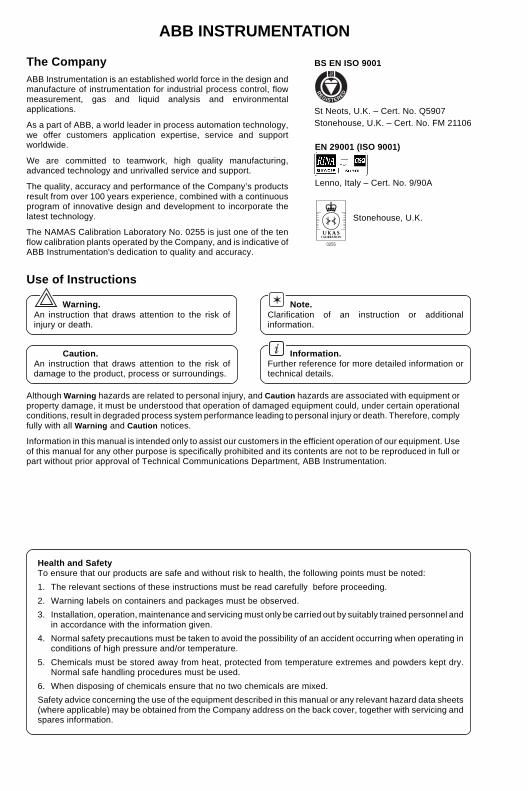
ABB INSTRUMENTATION
BS EN ISO 9001
St Neots, U.K. – Cert. No. Q5907Stonehouse, U.K. – Cert. No. FM 21106
The CompanyABB Instrumentation is an established world force in the design andmanufacture of instrumentation for industrial process control, flowmeasurement, gas and liquid analysis and environmentalapplications.
As a part of ABB, a world leader in process automation technology,we offer customers application expertise, service and supportworldwide.
We are committed to teamwork, high quality manufacturing,advanced technology and unrivalled service and support.
The quality, accuracy and performance of the Company’s productsresult from over 100 years experience, combined with a continuousprogram of innovative design and development to incorporate thelatest technology.
The NAMAS Calibration Laboratory No. 0255 is just one of the tenflow calibration plants operated by the Company, and is indicative ofABB Instrumentation's dedication to quality and accuracy.
Health and SafetyTo ensure that our products are safe and without risk to health, the following points must be noted:
1. The relevant sections of these instructions must be read carefully before proceeding.
2. Warning labels on containers and packages must be observed.
3. Installation, operation, maintenance and servicing must only be carried out by suitably trained personnel andin accordance with the information given.
4. Normal safety precautions must be taken to avoid the possibility of an accident occurring when operating inconditions of high pressure and/or temperature.
5. Chemicals must be stored away from heat, protected from temperature extremes and powders kept dry.Normal safe handling procedures must be used.
6. When disposing of chemicals ensure that no two chemicals are mixed.
Safety advice concerning the use of the equipment described in this manual or any relevant hazard data sheets(where applicable) may be obtained from the Company address on the back cover, together with servicing andspares information.
✶ Note.Clarification of an instruction or additionalinformation.
Information.Further reference for more detailed information ortechnical details.
Although Warning hazards are related to personal injury, and Caution hazards are associated with equipment orproperty damage, it must be understood that operation of damaged equipment could, under certain operationalconditions, result in degraded process system performance leading to personal injury or death. Therefore, complyfully with all Warning and Caution notices.
Information in this manual is intended only to assist our customers in the efficient operation of our equipment. Useof this manual for any other purpose is specifically prohibited and its contents are not to be reproduced in full orpart without prior approval of Technical Communications Department, ABB Instrumentation.
EN 29001 (ISO 9001)
Lenno, Italy – Cert. No. 9/90A
Use of Instructions
Warning.An instruction that draws attention to the risk ofinjury or death.
Caution.An instruction that draws attention to the risk ofdamage to the product, process or surroundings.
Stonehouse, U.K.
0255
REGISTERE
D
1
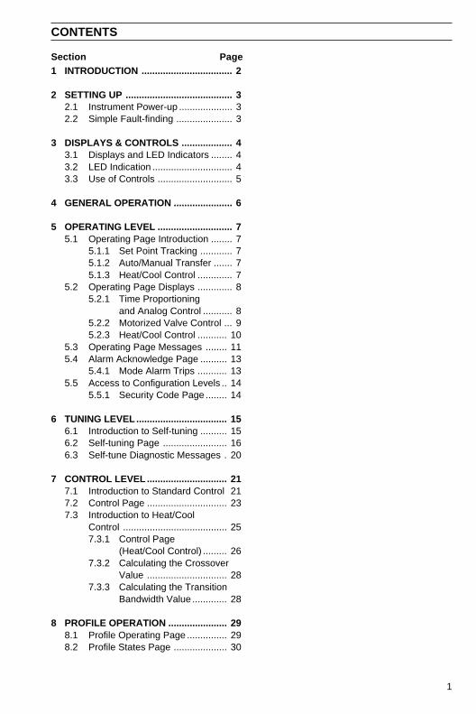
CONTENTS
Section Page1 INTRODUCTION .................................. 2
2 SETTING UP ........................................ 32.1 Instrument Power-up .................... 32.2 Simple Fault-finding ..................... 3
3 DISPLAYS & CONTROLS ................... 43.1 Displays and LED Indicators ........ 43.2 LED Indication .............................. 43.3 Use of Controls ............................ 5
4 GENERAL OPERATION ...................... 6
5 OPERATING LEVEL ............................ 75.1 Operating Page Introduction ........ 7
5.1.1 Set Point Tracking ............ 75.1.2 Auto/Manual Transfer ....... 75.1.3 Heat/Cool Control ............. 7
5.2 Operating Page Displays ............. 85.2.1 Time Proportioning
and Analog Control ........... 85.2.2 Motorized Valve Control ... 95.2.3 Heat/Cool Control ........... 10
5.3 Operating Page Messages ........ 115.4 Alarm Acknowledge Page .......... 13
5.4.1 Mode Alarm Trips ........... 135.5 Access to Configuration Levels .. 14
5.5.1 Security Code Page ........ 14
6 TUNING LEVEL .................................. 156.1 Introduction to Self-tuning .......... 156.2 Self-tuning Page ........................ 166.3 Self-tune Diagnostic Messages . 20
7 CONTROL LEVEL .............................. 217.1 Introduction to Standard Control 217.2 Control Page .............................. 237.3 Introduction to Heat/Cool
Control ....................................... 257.3.1 Control Page
(Heat/Cool Control) ......... 267.3.2 Calculating the Crossover
Value .............................. 287.3.3 Calculating the Transition
Bandwidth Value ............. 28
8 PROFILE OPERATION ...................... 298.1 Profile Operating Page ............... 298.2 Profile States Page .................... 30
2
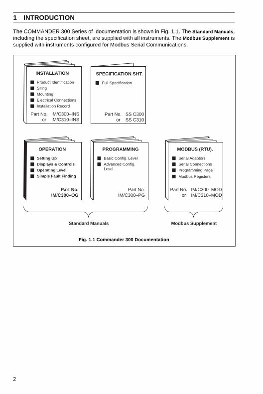
The COMMANDER 300 Series of documentation is shown in Fig. 1.1. The Standard Manuals ,including the specification sheet, are supplied with all instruments. The Modbus Supplement issupplied with instruments configured for Modbus Serial Communications.
1 INTRODUCTION
Fig. 1.1 Commander 300 Documentation
PROGRAMMING
Part No.IM/C300–PG
Basic Config. Level
Advanced Config.Level
OPERATION
Setting Up
Displays & Controls
Operating Level
Simple Fault Finding
Part No.IM/C300–OG
Part No. IM/C300–INS or IM/C310–INS
INSTALLATION
Product Identification
Siting
Mounting
Electrical Connections
Installation Record
MODBUS (RTU).
Serial Adaptors
Serial Connections
Programming Page
Part No. IM/C300–MODor IM/C310–MOD
SPECIFICATION SHT.
Full Specification
Part No. SS C300or SS C310
Modbus Registers
Standard Manuals Modbus Supplement
3
2 SETTING UP
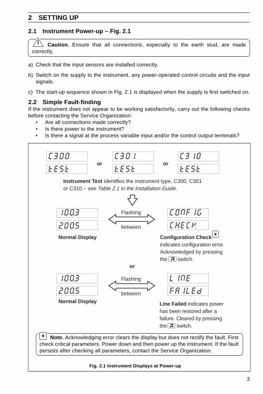
2.1 Instrument Power-up – Fig. 2.1
Caution. Ensure that all connections, especially to the earth stud, are madecorrectly.
a) Check that the input sensors are installed correctly.
b) Switch on the supply to the instrument, any power-operated control circuits and the inputsignals.
c) The start-up sequence shown in Fig. 2.1 is displayed when the supply is first switched on.
2.2 Simple Fault-findingIf the instrument does not appear to be working satisfactorliy, carry out the following checksbefore contacting the Service Organization:
• Are all connections made correctly?• Is there power to the instrument?• Is there a signal at the process variable input and/or the control output terminals?
Line Failed indicates powerhas been restored after afailure. Cleared by pressingthe switch.
Instrument Test identifies the instrument type, C300, C301or C310 – see Table 2.1 in the Installation Guide.
orC300
tESt
Configuration Checkindicates configuration error.Acknowledged by pressingthe switch.
C310
tESt
LINE
FAILEd
Flashing
between
CONFIG
CHECK
Flashing
between
or
100.3
200.5
100.3
200.5
Normal Display
Normal Display
C301
tEStor
Fig. 2.1 Instrument Displays at Power-up
Note. Acknowledging error clears the display but does not rectify the fault. Firstcheck critical parameters. Power down and then power up the instrument. If the faultpersists after checking all parameters, contact the Service Organization.
4
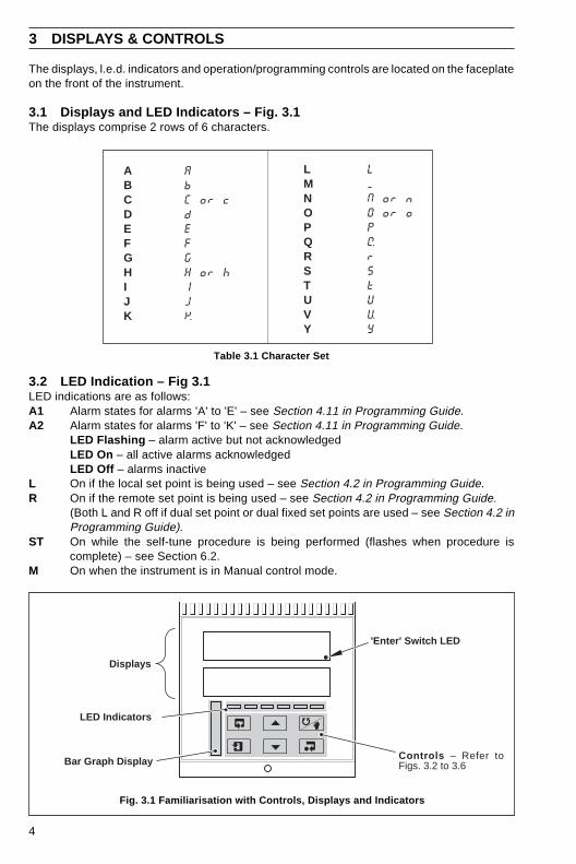
The displays, l.e.d. indicators and operation/programming controls are located on the faceplateon the front of the instrument.
3.1 Displays and LED Indicators – Fig. 3.1The displays comprise 2 rows of 6 characters.
3 DISPLAYS & CONTROLS
Table 3.1 Character Set
Fig. 3.1 Familiarisation with Controls, Displays and Indicators
3.2 LED Indication – Fig 3.1LED indications are as follows:A1 Alarm states for alarms 'A' to 'E' – see Section 4.11 in Programming Guide.A2 Alarm states for alarms 'F' to 'K' – see Section 4.11 in Programming Guide.
LED Flashing – alarm active but not acknowledgedLED On – all active alarms acknowledgedLED Off – alarms inactive
L On if the local set point is being used – see Section 4.2 in Programming Guide.R On if the remote set point is being used – see Section 4.2 in Programming Guide.
(Both L and R off if dual set point or dual fixed set points are used – see Section 4.2 inProgramming Guide).
ST On while the self-tune procedure is being performed (flashes when procedure iscomplete) – see Section 6.2.
M On when the instrument is in Manual control mode.
'Enter' Switch LED
Bar Graph Display
LED Indicators
Controls – Refer toFigs. 3.2 to 3.6
Displays
AbC or cdEFGH or hIJK
LMN or nO or oPQrStUVY
ABCDEFGHIJK
LMNOPQRSTUVY
5
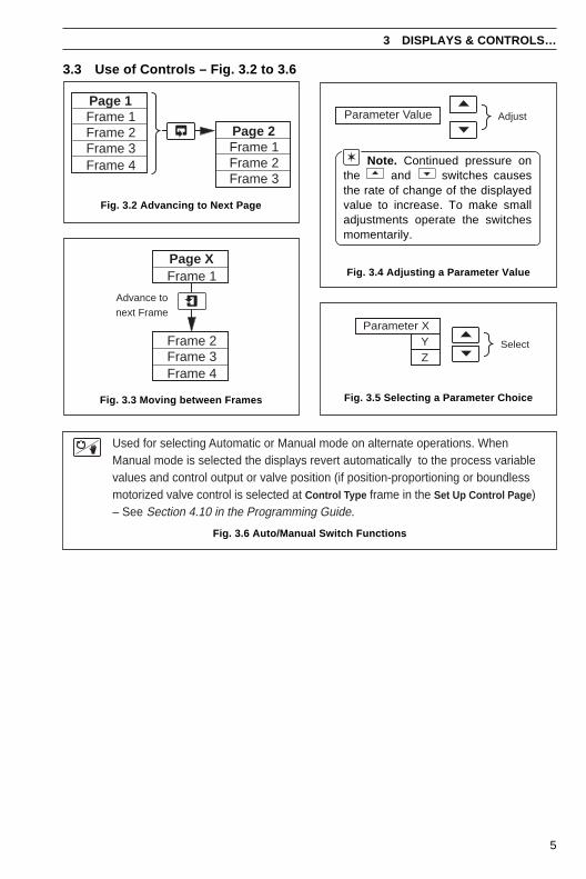
3.3 Use of Controls – Fig. 3.2 to 3.6
3 DISPLAYS & CONTROLS…
Fig. 3.2 Advancing to Next Page
Fig. 3.3 Moving between Frames
Note. Continued pressure onthe and switches causesthe rate of change of the displayedvalue to increase. To make smalladjustments operate the switchesmomentarily.
Fig. 3.4 Adjusting a Parameter Value
Fig. 3.5 Selecting a Parameter Choice
Used for selecting Automatic or Manual mode on alternate operations. WhenManual mode is selected the displays revert automatically to the process variablevalues and control output or valve position (if position-proportioning or boundlessmotorized valve control is selected at Control Type frame in the Set Up Control Page )– See Section 4.10 in the Programming Guide.
Fig. 3.6 Auto/Manual Switch Functions
Frame 1Frame 2Frame 3Frame 4
Page 1
Frame 1Frame 2Frame 3
Page 2
Frame 1
Frame 2Frame 3
Page X
Frame 4
Advance tonext Frame
AdjustParameter Value
Parameter XYZ
Select
6
4 GENERAL OPERATION
Fig
. 4.1
Sum
mar
y of
Ope
ratin
g Le
vels
Pro
gram
min
gP
ages
– S
eeP
rogr
amm
ing
Gui
de.
SELF
tUNE
PrOFLE
StAtES
SECOdE
MMMM
P-StAt
MMMM
ACKNLG
ALArMS
CONtrL
PAGE
000.00
000.00
Pro
cess
Var
iabl
e
Ope
ratin
g P
age
(Sec
tion
5.2,
Pag
e 8)
Ala
rm A
ckno
wle
dge
Pag
e(S
ectio
n 5.
4, P
age
13)
Sec
urity
Cod
e P
age
(Sec
tion
5.5,
Pag
e 14
)
Pro
file
Ope
ratin
g P
age*
(Sec
tion
8.1,
Pag
e 29
)S
elf-
tuni
ng P
age†
(Sec
tion
6.2,
Pag
e 16
)
Con
trol
Pag
e(S
ectio
n 7.
2, P
age
23)
Pro
file
Sta
tes
Pag
e*(S
ectio
n 8.
2,P
age
30)
Set
Poi
nt
*Pag
e hi
dden
if P
rofil
e F
unct
ion
is 'O
FF
'
†Pag
e hi
dden
if P
rofil
e F
unct
ion
is 'O
N' o
r 'B
ound
less
' con
trol
is s
elec
ted
Inco
rrec
t Sec
urity
Cod
eC
orre
ct S
ecur
ity C
ode
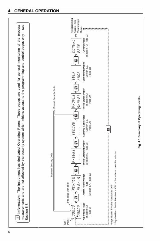
Info
rmat
ion.
The
ins
trum
ent
has
dedi
cate
d O
pera
ting
Pag
es.
The
se p
ages
are
use
d fo
r ge
nera
l m
onito
ring
of t
he p
roce
ssm
easu
rem
ents
and
are
not
affe
cted
by
the
secu
rity
syst
em w
hich
inh
ibits
acc
ess
to t
he p
rogr
amm
ing
and
cont
rol
page
s on
ly –
see
Sec
tion
5.5.
7
5 OPERATING LEVEL
5.1 Operating Page Introduction
5.1.1 Set Point TrackingWith set point tracking enabled (in the Set Points Page ), the Local set point value tracks theprocess variable when the controller is in Manual control mode. In this mode of operation theset point limits do not apply. If the set point value is outside its limits when Automatic controlmode is selected, the local set point remains outside its limits and can only be adjusted in onedirection, towards its limits. Once inside the limits they apply as normal.
With remote set point tracking enabled, the Local set point tracks the remote set point valuewhen in the remote set point mode. In this mode of operation the Local set point limits do notapply. If the set point value is outside its limits when the Local set point value is selected, theLocal set point remains outside its limits and can only be adjusted in one direction, towards itslimits. Once inside the limits they apply as normal.
5.1.2 Auto/Manual TransferAll auto-to-manual transfers are bumpless. If the Local set point is used and set point trackingis enabled, all manual-to-auto transfers are bumpless, since the set point is always at the samevalue as the process variable. Without set point tracking enabled, the response following amanual-to-auto transfer depends on the control settings. With an integral action setting theoutput is ramped up or down to remove any process variable offset from the set point (providingthe process variable is within the proportional band). If the integral action is off, the output maystep to a new value when the controller is transferred back to Automatic control mode.
With remote set point tracking enabled, the control set point switches automatically fromRemote to Local when Manual mode is selected.
5.1.3 Heat/Cool Control – Fig. 6.3When in Automatic control mode both the heat and cool outputs are turned off when in theOutput Off Hysteresis Band. In Manual control mode the Output Off Hysteresis Band has noeffect. If the PID output is within the Off Hysteresis Band when the controller is returned to autocontrol mode, the Off Hysteresis Band has no effect until either the PID output goes outside theband or becomes equal to the Crossover Value.
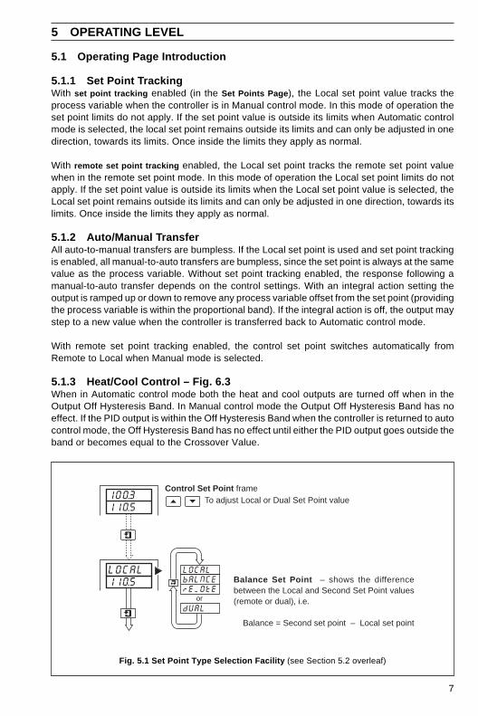
Fig. 5.1 Set Point Type Selection Facility (see Section 5.2 overleaf)
100.3110.5
LOCAL110.5
LOCALbALNCErEMOtE
dUALor
Control Set Point frame
Balance Set Point – shows the differencebetween the Local and Second Set Point values(remote or dual), i.e.
Balance = Second set point – Local set point
To adjust Local or Dual Set Point value
8
…5 OPERATING LEVEL
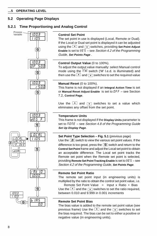
Control Set PointThe set point in use is displayed (Local, Remote or Dual).If the Local or Dual set point is displayed it can be adjustedusing the and switches, providing Set Point AdjustEnable is set to YES – see Section 4.2 of the ProgrammingGuide, Set Points Page .
Control Output Value (0 to 100%).To adjust the output value manually: select Manual controlmode using the switch ('M' l.e.d. is illuminated) andthen use the and switches to set the required value
Manual Reset (0 to 100%).This frame is not displayed if an Integral Action Time is setor Manual Reset Adjust Enable is set to OFF – see Section7.2, Control Page .
Use the and switches to set a value whicheliminates any offset from the set point.
Temperature UnitsThis frame is not displayed if the Display Units parameter isset to NONE – see Section 4.8 of the Programming GuideSet Up Display Page .
Set Point Type Selection – Fig. 5.1 (previous page)Use the switch to view the various set point values. If thedifference is too great, press the switch and return to theControl Set Point frame and adjust the Local set point to obtainan acceptable difference. The Local set point tracks theRemote set point when the Remote set point is selected,providing Remote Set Point Tracking Enable is set to YES – seeSection 4.2 of the Programming Guide, Set Points Page .
Remote Set Point RatioThe remote set point input (in engineering units) ismultiplied by the ratio to obtain the control set point value, i.e.
Remote Set Point Value = Input x Ratio + BiasUse the and the switches to set the ratio required,between 0.010 and 9.999 in 0.001 increments
Remote Set Point BiasThe bias value is added to the remote set point value (seeprevious frame) Use the and the switches to setthe bias required. The bias can be set to either a positive ornegative value (in engineering units).
100.3OP 50.0
100.3 r50.0
100.3110.5
100.3dEG F
LOCAL110.5LOCAL
bALNCErEMOtE
dUALor
rAtIO1.000
bIAS 0.0
100.3110.3
ProcessVariable
5.2 Operating Page Displays
5.2.1 Time Proportioning and Analog Control
9
5 OPERATING LEVEL…
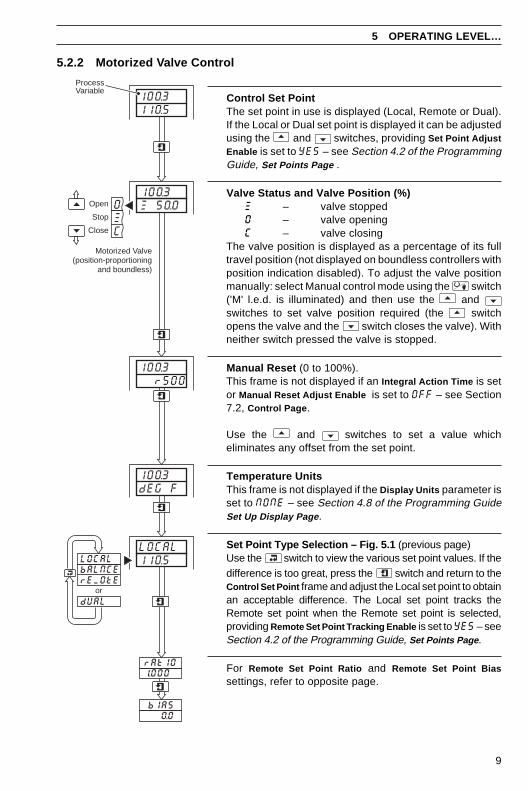
5.2.2 Motorized Valve Control
Control Set PointThe set point in use is displayed (Local, Remote or Dual).If the Local or Dual set point is displayed it can be adjustedusing the and switches, providing Set Point AdjustEnable is set to YES – see Section 4.2 of the ProgrammingGuide, Set Points Page .
Valve Status and Valve Position (%)W – valve stoppedO – valve openingC – valve closing
The valve position is displayed as a percentage of its fulltravel position (not displayed on boundless controllers withposition indication disabled). To adjust the valve positionmanually: select Manual control mode using the switch('M' l.e.d. is illuminated) and then use the and switches to set valve position required (the switchopens the valve and the switch closes the valve). Withneither switch pressed the valve is stopped.
Manual Reset (0 to 100%).This frame is not displayed if an Integral Action Time is setor Manual Reset Adjust Enable is set to OFF – see Section7.2, Control Page .
Use the and switches to set a value whicheliminates any offset from the set point.
Temperature UnitsThis frame is not displayed if the Display Units parameter isset to NONE – see Section 4.8 of the Programming GuideSet Up Display Page .
Set Point Type Selection – Fig. 5.1 (previous page)Use the switch to view the various set point values. If thedifference is too great, press the switch and return to theControl Set Point frame and adjust the Local set point to obtainan acceptable difference. The Local set point tracks theRemote set point when the Remote set point is selected,providing Remote Set Point Tracking Enable is set to YES – seeSection 4.2 of the Programming Guide, Set Points Page .
For Remote Set Point Ratio and Remote Set Point Biassettings, refer to opposite page.
100.3110.5
OWC
100.3W 50.0Open
Close
Stop
Motorized Valve(position-proportioning
and boundless)
100.3dEG F
LOCAL110.5LOCAL
bALNCErEMOtE
dUALor
rAtIO1.000
100.3 r500
bIAS 0.0
ProcessVariable
10
…5 OPERATING LEVEL
Manual Reset (Heat) Manual Reset (Cool)
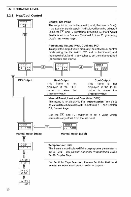
Control Set PointThe set point in use is displayed (Local, Remote or Dual).If the Local or Dual set point is displayed it can be adjustedusing the and switches, providing Set Point AdjustEnable is set to YES – see Section 4.2 of the ProgrammingGuide, Set Points Page .
Percentage Output (Heat, Cool and PID)To adjust the output value manually: select Manual controlmode using the switch ('M' l.e.d. is illuminated) andthen use the and switches to set the value required(between 0 and 100%).
Cool OutputThis frame is notdisplayed if the P.I.D.output is above theCrossover Value .
Heat OutputThis frame is notdisplayed if the P.I.D.output is below theCrossover Value .
PID Output
100.3110.5
100.3OP 50.0
100.3oh 50.0
100.3oc 50.0
100.3rc 50.0
100.3rh 50.0
100.3dEG F
rAtIO1.000
bIAS 0.0
LOCAL110.5
Manual Reset, Heat and Cool (0 to 100%).This frame is not displayed if an Integral Action Time is setor Manual Reset Adjust Enable is set to OFF – see Section7.2, Control Page .
Use the and switches to set a value whicheliminates any offset from the set point.
Temperature UnitsThis frame is not displayed if the Display Units parameter isset to NONE – see Section 4.8 of the Programming GuideSet Up Display Page .
For Set Point Type Selection , Remote Set Point Ratio andRemote Set Point Bias settings, refer to page 8.
5.2.3 Heat/Cool Control
11
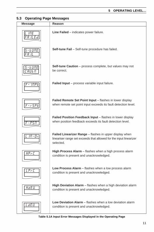
5.3 Operating Page Messages
5 OPERATING LEVEL…
Table 5.1A Input Error Messages Displayed in the Operating Page
Reason
Line Failed – indicates power failure.
Self-tune Fail – Self-tune procedure has failed.
Self-tune Caution – process complete, but values may notbe correct.
Failed Input – process variable input failure.
Failed Remote Set Point Input – flashes in lower displaywhen remote set point input exceeds its fault detection level.
Failed Position Feedback Input – flashes in lower displaywhen position feedback exceeds its fault detection level.
Failed Linearizer Range – flashes in upper display whenlineariser range set exceeds that allowed for the input linearizerselected.
High Process Alarm – flashes when a high process alarmcondition is present and unacknowledged.
Low Process Alarm – flashes when a low process alarmcondition is present and unacknowledged.
High Deviation Alarm – flashes when a high deviation alarmcondition is present and unacknowledged.
Low Deviation Alarm – flashes when a low deviation alarmcondition is present and unacknowledged.
Message
HPrC
S-tUNEFAIL
S-tUNECAUtN
F-PSN
LIN-Or
F-INPt
F-rSPt
LPrC
HdEV
LdEV
LINEFAILEd
12
…5 OPERATING LEVEL
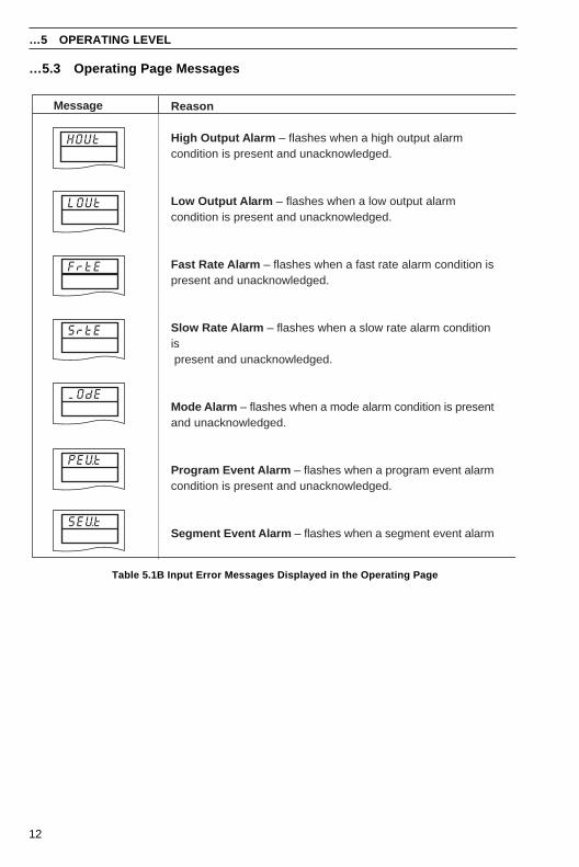
…5.3 Operating Page Messages
MOdE
PEVt
SEVt
Message Reason
High Output Alarm – flashes when a high output alarmcondition is present and unacknowledged.
Low Output Alarm – flashes when a low output alarmcondition is present and unacknowledged.
Fast Rate Alarm – flashes when a fast rate alarm condition ispresent and unacknowledged.
Slow Rate Alarm – flashes when a slow rate alarm conditionis present and unacknowledged.
Mode Alarm – flashes when a mode alarm condition is presentand unacknowledged.
Program Event Alarm – flashes when a program event alarmcondition is present and unacknowledged.
Segment Event Alarm – flashes when a segment event alarm
LOUt
HOUt
FrtE
SrtE
Table 5.1B Input Error Messages Displayed in the Operating Page
13
5 OPERATING LEVEL…
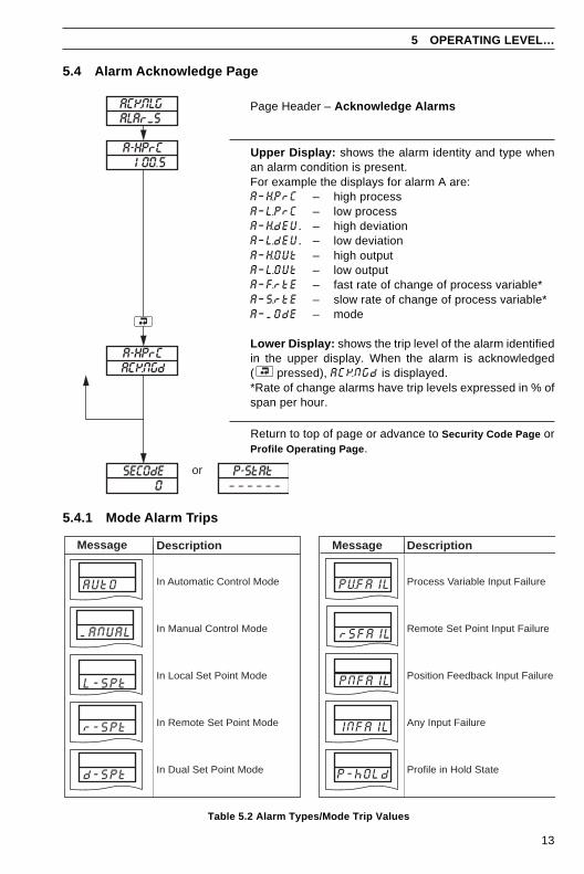
Page Header – Acknowledge Alarms
Upper Display: shows the alarm identity and type whenan alarm condition is present.For example the displays for alarm A are:A–H.PrC – high processA–L.PrC – low processA–H.dEU. – high deviationA–L.dEU. – low deviationA–H.OUt – high outputA–L.OUt – low outputA–F.rtE – fast rate of change of process variable*A–S.rtE – slow rate of change of process variable*A–MOdE – mode
Lower Display: shows the trip level of the alarm identifiedin the upper display. When the alarm is acknowledged( pressed), ACKNGd is displayed.*Rate of change alarms have trip levels expressed in % ofspan per hour.
Return to top of page or advance to Security Code Page orProfile Operating Page .
5.4 Alarm Acknowledge Page
Table 5.2 Alarm Types/Mode Trip Values
5.4.1 Mode Alarm Trips
ACKNLGALArMS
SECOdE0
P-StAt– – – – – –
or
A-HPrC100.5
ACKNGdA-HPrC
Message Description
In Automatic Control Mode
In Manual Control Mode
In Local Set Point Mode
In Remote Set Point Mode
In Dual Set Point Mode
AUtO
MANUAL
r-SPt
d-SPt
L-SPt
rSFAIL
PVFAIL
PNFAIL
INFAIL
P-hOLd
Description
Process Variable Input Failure
Remote Set Point Input Failure
Position Feedback Input Failure
Any Input Failure
Profile in Hold State
Message
14
…5 OPERATING LEVEL
5.5 Access to Configuration LevelsA security system is used to prevent tampering with the program parameters by utilizing a Tunepassword and a Configuration password.
The Tune password gives access to the self-tune and control pages.
The Configuration password gives access to all controller settings and programming pages –see Section 4.15 of the Programming Guide.
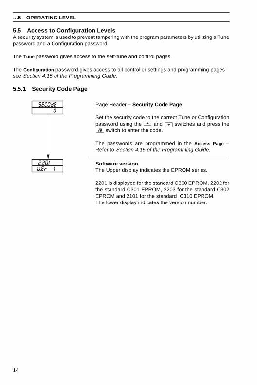
5.5.1 Security Code Page
Page Header – Security Code Page
Set the security code to the correct Tune or Configurationpassword using the and switches and press the
switch to enter the code.
The passwords are programmed in the Access Page –Refer to Section 4.15 of the Programming Guide.
Software versionThe Upper display indicates the EPROM series.
2201 is displayed for the standard C300 EPROM, 2202 forthe standard C301 EPROM, 2203 for the standard C302EPROM and 2101 for the standard C310 EPROM.The lower display indicates the version number.
SECOdE
VEr 12201
0
15
6 TUNING LEVEL
6.1 Introduction to Self-tuning
Information.• On demand user-activated tuning.
• Two types of self-tuning – initial 'Start-up' and when close to 'Set Point' .
• Tuning for P, PI or PID control can be selected.
• Tuning for 1/4 wave damped or minimum overshoot (start-up tuning only) can beselected.
• Error and Caution messages – indicate reason for tuning problems.
• Self-tune facility – not available on Heat/Cool Control and Boundless.
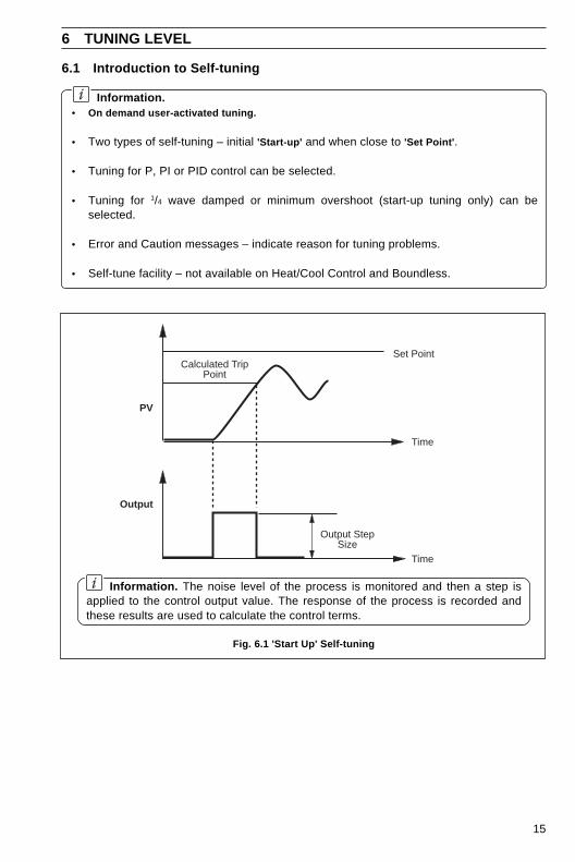
Fig. 6.1 'Start Up' Self-tuning
Information. The noise level of the process is monitored and then a step isapplied to the control output value. The response of the process is recorded andthese results are used to calculate the control terms.
Set Point
PV
Output
Time
Output StepSize
Time
Calculated TripPoint
16
…6 TUNING LEVEL
…6.1 Introduction to Self-tuning
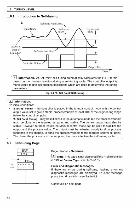
Information. 'At Set Point' self-tuning automatically calculates the P.I.D. termsbased on the process reaction during a self-tuning cycle. The controller output ismanipulated to give six process oscillations which are used to determine the tuningparameters.
Fig. 6.2 'At Set Point' Self-tuning
Information.On initial conditions:• 'Start-up' Tuning – the controller is placed in the Manual control mode with the control
output value set to give a stable process variable at least 10% of the engineering rangebelow the control set point.
• 'At Set Point ' Tuning – may be initialized in the automatic mode but the process variablemust be close to the required set point and stable. The control output must also bestable. However, for best results the Manual control mode can be used to stabilize theoutput and the process value. The output must be adjusted slowly to allow processresponse to the change, to bring the process variable to the required control set point.The closer the process is to the set point, the more effective the self-tuning cycle.
6.2 Self-tuning Page
SELF
– – – – – –– – – – – –
Error
NoError
tUNE
Self-tune High Limit
Self-tune Low Limit
HysteresisBand
HysteresisValue
Output Step
Values atStart of
Execution
Controller Output
Time
Signal Noise
Page Header – Self-tune.
Note. This page is not displayed if the Profile Functionis 'ON' or Control Type is set to 'bNdLSS'
Error and Diagnostic MessagesIf there are errors during self-tune, flashing error anddiagnostic messages are displayed. To clear message,press the switch – see Table 6.1.
Continued on next page
17
…6.2 Self-tuning Page
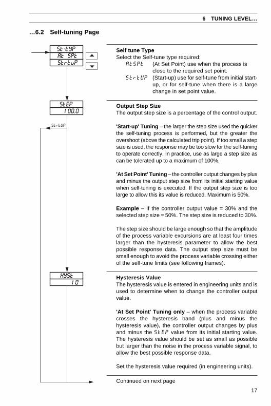
Self tune TypeSelect the Self-tune type required:
AtSPt (At Set Point) use when the process isclose to the required set point.
StrtUP (Start-up) use for self-tune from initial start-up, or for self-tune when there is a largechange in set point value.
Output Step SizeThe output step size is a percentage of the control output.
'Start-up' Tuning – the larger the step size used the quickerthe self-tuning process is performed, but the greater theovershoot (above the calculated trip point). If too small a stepsize is used, the response may be too slow for the self-tuningto operate correctly. In practice, use as large a step size ascan be tolerated up to a maximum of 100%.
'At Set Point' Tuning – the controller output changes by plusand minus the output step size from its initial starting valuewhen self-tuning is executed. If the output step size is toolarge to allow this its value is reduced. Maximum is 50%.
Example – If the controller output value = 30% and theselected step size = 50%. The step size is reduced to 30%.
The step size should be large enough so that the amplitudeof the process variable excursions are at least four timeslarger than the hysteresis parameter to allow the bestpossible response data. The output step size must besmall enough to avoid the process variable crossing eitherof the self-tune limits (see following frames).
Hysteresis ValueThe hysteresis value is entered in engineering units and isused to determine when to change the controller outputvalue.
'At Set Point' Tuning only – when the process variablecrosses the hysteresis band (plus and minus thehysteresis value), the controller output changes by plusand minus the StEP value from its initial starting value.The hysteresis value should be set as small as possiblebut larger than the noise in the process variable signal, toallow the best possible response data.
Set the hysteresis value required (in engineering units).
Continued on next page
6 TUNING LEVEL…
StrtUP
HYSt10
StEP100.0
St-tYPAt SPtStrtuP
18
…6.2 Self-tuning Page
…6 TUNING LEVEL
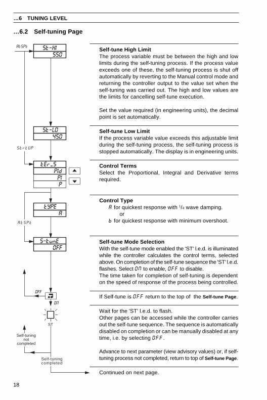
Self-tune High LimitThe process variable must be between the high and lowlimits during the self-tuning process. If the process valueexceeds one of these, the self-tuning process is shut offautomatically by reverting to the Manual control mode andreturning the controller output to the value set when theself-tuning was carried out. The high and low values arethe limits for cancelling self-tune execution.
Set the value required (in engineering units), the decimalpoint is set automatically.
Self-tune Low LimitIf the process variable value exceeds this adjustable limitduring the self-tuning process, the self-tuning process isstopped automatically. The display is in engineering units.
Control TermsSelect the Proportional, Integral and Derivative termsrequired.
Control TypeA for quickest response with 1/4 wave damping. orb for quickest response with minimum overshoot.
Self-tune Mode SelectionWith the self-tune mode enabled the 'ST' l.e.d. is illuminatedwhile the controller calculates the control terms, selectedabove. On completion of the self-tune sequence the 'ST' l.e.d.flashes. Select ON to enable, OFF to disable.The time taken for completion of self-tuning is dependenton the speed of response of the process being controlled.
If Self-tune is OFF return to the top of the Self-tune Page .
Wait for the 'ST' l.e.d. to flash.Other pages can be accessed while the controller carriesout the self-tune sequence. The sequence is automaticallydisabled on completion or can be manually disabled at anytime, i.e. by selecting OFF.
Advance to next parameter (view advisory values) or, if self-tuning process not completed, return to top of Self-tune Page .
Continued on next page.
tYPEA
S–tunEOFF
AtSPt
A t S P t
ST
Self-tuningnot
completed
Self-tuningcompleted
OFF
ON
St–HI550
tErMSPId
PIP
St–LO450
StrtUP
19
6 TUNING LEVEL…
…6.2 Self-tuning Page
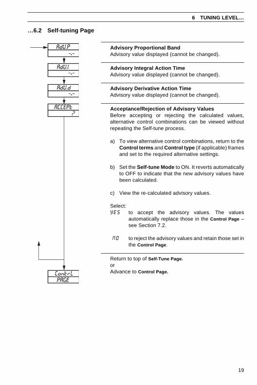
Advisory Proportional BandAdvisory value displayed (cannot be changed).
Advisory Integral Action TimeAdvisory value displayed (cannot be changed).
Advisory Derivative Action TimeAdvisory value displayed (cannot be changed).
Acceptance/Rejection of Advisory ValuesBefore accepting or rejecting the calculated values,alternative control combinations can be viewed withoutrepeating the Self-tune process.
a) To view alternative control combinations, return to theControl terms and Control type (if applicable) framesand set to the required alternative settings.
b) Set the Self-tune Mode to ON. It reverts automaticallyto OFF to indicate that the new advisory values havebeen calculated.
c) View the re-calculated advisory values.
Select:YES to accept the advisory values. The values
automatically replace those in the Control Page –see Section 7.2.
NO to reject the advisory values and retain those set inthe Control Page .
Return to top of Self-Tune Page.orAdvance to Control Page.
AdU.P
–•–AdU.I
AdU.d
ACCEPt
ContrLPAGE
?
–•–
–•–
20
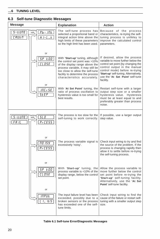
6.3 Self-tune Diagnostic Messages
…6 TUNING LEVEL
Table 6.1 Self-tune Error/Diagnostic Messages
Pb–INt
HI–LMt
SP tOO
CLOSE
INCrSE
StEP
SLO
PrCESS
NOISY
CLOSE
SP tOO
PrCESS
INPUt
LIMItS
S–tUNE
CAUtN
S–tUNE
FAIL
Flashingwith
or
or
Flashingwith
or
or
or
Message Explanation Action
The process is too slow for theself-tuning to work correctly.
The input failure level has beenexceeded, possibly due to abroken sensors or the processhas exceeded one of the self-tune limits.
With 'At Set Point' tuning, theratio of process oscillation tohysteresis value is too small forbest results.
The self-tune process hasselected a proportional band orintegral action time above thehigh limits of these parametersso the high limit has been used.
Because o f the p rocesscharacteristics, re-trying the self-tuning process is unlikley toimprove the calculated controlparameters.
Restart self-tune with a largeroutput step size or a smallerhysteresis value. Hysteresismust be at least equal to andpreferably greater than processnoise.
If possible, use a larger outputstep value.
Check input wiring to find thecause of the failure or restart self-tuning with a smaller output stepsize.
The process variable signal isexcessively 'noisy'.
Check input wiring to try and findthe source of the problem. If theprocess is changing rapidly thenallow it to settle before re-tryingthe self-tuning process.
With 'Start-up' tuning, theprocess variable is <10% of thedisplay range, below the controlset point.
Allow the process variable tomove further below the controlset point before re-trying the'Start-up' self-tuning facility.Alternatively, use the 'At SetPoint' self-tune facility.
With 'Start-up' tuning, althoughthe control set point was >10%of the display range above theprocess variable, it may still betoo close to allow the self-tunefacility to determine the processcharacterist ics accurately.
If desired, allow the processvariable to move further below thecontrol set point (by changing thecontrol output in the manualcontrol mode) before re-trying'Start-up' self-tuning. Alternatively,use the 'At Set Point' self-tunefacility.
21
7.1 Introduction to Standard Control
Information.• On/Off Control – use for applications where precise control is not required, or where frequent
switching of a contactor using time proportioning control causes premature wear.
• Proportional Control – use where:cycling action of on/off control is unacceptable,load changes are small or infrequent,offset can be tolerated or eliminated using manual reset.
• Integral Action – introduce to the control system:to eliminate offset automatically,if set point or load changes frequently.
• Derivative Action – introduce to the control system:to enable faster approach to the set point (by enabling use of a smaller proportional band),to minimize overshoot.
7 CONTROL LEVEL
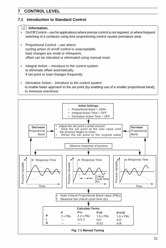
Fig. 7.1 Manual Tuning
IncreaseProportionalBand
PID
P2 x PBc——
P+I2.2 x PBctc/1.2—
P+D1.6 x PBctc/2tc/12
Time
Pro
cess
Var
iabl
e
Response Time
Time
Pro
cess
Var
iabl
e
Response Time
Pro
cess
Var
iabl
e
Response Time
CriticalCycle time(tcc
DecreaseProportional
Band
Calculate TermsP+I+D1.6 x PBctc/2tc/8
• Adjust the set point a small amount• Hold the set point at the new value until the process begins to move• Reset the set point to the original value
Observe response of process
• Note Critical Proportional Band value (PBc)• Measure the critical cycle time (tc)
Initial Settings• Proportional Band = 100%• Integral Action Time = OFF• Derivative Action Time = OFF
22
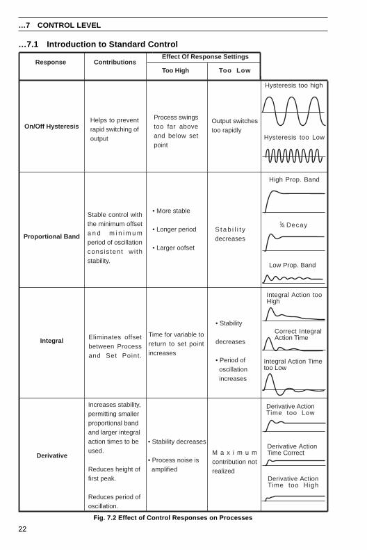
Fig. 7.2 Effect of Control Responses on Processes
…7.1 Introduction to Standard Control
…7 CONTROL LEVEL
Response ContributionsEffect Of Response Settings
Too High Too Low
On/Off HysteresisHelps to preventrapid switching ofoutput
Process swingstoo far aboveand below setpoint
Output switchestoo rapidly
Hysteresis too high
Hysteresis too Low
Proportional Band
Stable control withthe minimum offseta n d m i n i m u mperiod of oscillationconsis tent wi thstability.
• More stable
• Longer period
• Larger oofset
S t a b i l i t ydecreases
High Prop. Band
Low Prop. Band
Derivative
Increases stability,permitting smallerproportional bandand larger integralaction times to beused.
Reduces height offirst peak.
Reduces period ofoscillation.
• Stability decreases
• Process noise is amplified
M a x i m u mcontribution notrealized
Derivative ActionTime too High
Derivative ActionTime Correct
Derivative ActionTime too Low
Integral Eliminates offsetbetween Processand Set Point.
Time for variable toreturn to set pointincreases
• Stability
decreases
• Period of oscillation increases
Integral Action Timetoo Low
Integral Action tooHigh
Correct IntegralAction Time
Decay14
23
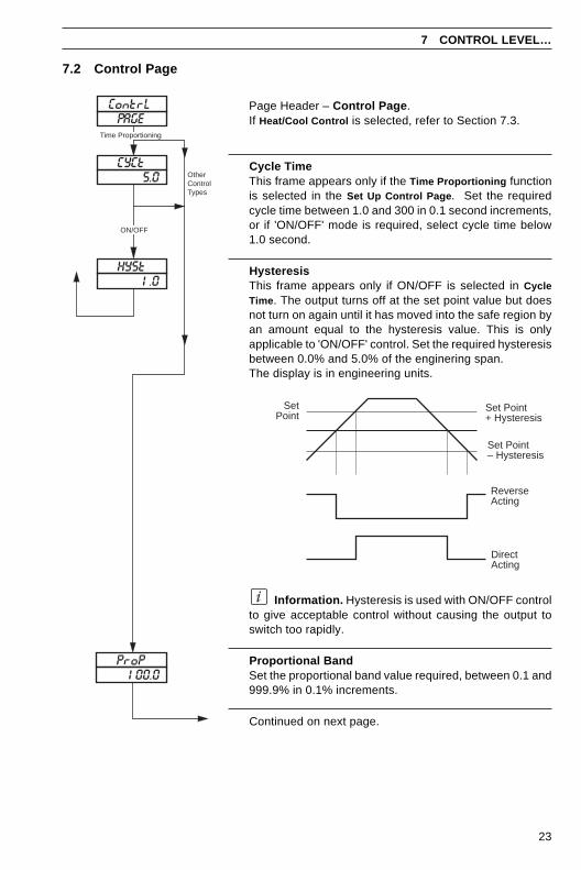
7.2 Control Page
Information. Hysteresis is used with ON/OFF controlto give acceptable control without causing the output toswitch too rapidly.
Proportional BandSet the proportional band value required, between 0.1 and999.9% in 0.1% increments.
Continued on next page.
Page Header – Control Page .If Heat/Cool Control is selected, refer to Section 7.3.
Cycle TimeThis frame appears only if the Time Proportioning functionis selected in the Set Up Control Page . Set the requiredcycle time between 1.0 and 300 in 0.1 second increments,or if 'ON/OFF' mode is required, select cycle time below1.0 second.
HysteresisThis frame appears only if ON/OFF is selected in CycleTime . The output turns off at the set point value but doesnot turn on again until it has moved into the safe region byan amount equal to the hysteresis value. This is onlyapplicable to 'ON/OFF' control. Set the required hysteresisbetween 0.0% and 5.0% of the enginering span.The display is in engineering units.
7 CONTROL LEVEL…
ContrL
CYCt5.0
HYSt1.0
ON/OFF
PAGETime Proportioning
OtherControlTypes
ProP100.0
SetPoint
ReverseActing
DirectActing
Set Point+ Hysteresis
Set Point– Hysteresis
24
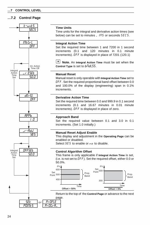
…7.2 Control Page
Return to the top of the Control Page or advance to the nextpage.
…7 CONTROL LEVEL
SetPoint
Prop.Band
500
600
400
TimeOffset = 50%
SetPoint
Prop.Band
500
Time
Offset = 0%
PV PV
300
orSEt
OFFSEt50.0
Mr–AdJ YES
PrOGrAMPrOFLE
POINtS
OFF
50.0
IntegralActionTimeSet
Int. ActionTime Off
OFF
APPb
M.r ESEt
INtGrL
dErIV
1.0
t–untSSECS
IntegralActionTimeSet
Time UnitsTime units for the integral and derivative action times (seebelow) can be set to minutes MINS or seconds SECS.
Integral Action TimeSet the required time between 1 and 7200 in 1 secondincrements (0.1 and 120 minutes in 0.1 minuteincrements). OFF is displayed in place of 7201 (120.1)
Note. An Integral Action Time must be set when theControl Type is set to bNdLSS.
Manual ResetManual reset is only operable with Integral Action Time set toOFF. Set the required proportional band offset between 0.0and 100.0% of the display (engineering) span in 0.1%increments.
Derivative Action TimeSet the required time between 0.0 and 999.9 in 0.1 secondincrements (0.1 and 16.67 minutes in 0.01 minuteincrements). OFF is displayed in place of zero.
Approach BandSet the required value between 0.1 and 3.0 in 0.1increments. (Set 1.0 initially.)
Manual Reset Adjust EnableThis display and adjustment in the Operating Page can beenabled or disabled.Select YES to enable or no to disable.
Control Algorithm OffsetThis frame is only applicable if Integral Action Time is set,(i.e. is not set to OFF). Set the required offset, either 0.0 or50.0%.
25
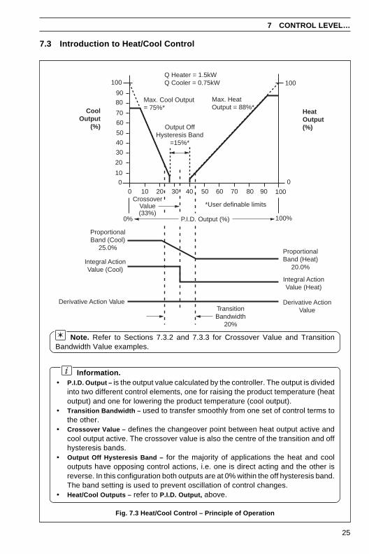
Fig. 7.3 Heat/Cool Control – Principle of Operation
7.3 Introduction to Heat/Cool Control
7 CONTROL LEVEL…
Information.• P.I.D. Output – is the output value calculated by the controller. The output is divided
into two different control elements, one for raising the product temperature (heatoutput) and one for lowering the product temperature (cool output).
• Transition Bandwidth – used to transfer smoothly from one set of control terms tothe other.
• Crossover Value – defines the changeover point between heat output active andcool output active. The crossover value is also the centre of the transition and offhysteresis bands.
• Output Off Hysteresis Band – for the majority of applications the heat and cooloutputs have opposing control actions, i.e. one is direct acting and the other isreverse. In this configuration both outputs are at 0% within the off hysteresis band.The band setting is used to prevent oscillation of control changes.
• Heat/Cool Outputs – refer to P.I.D. Output, above.
Note. Refer to Sections 7.3.2 and 7.3.3 for Crossover Value and TransitionBandwidth Value examples.
0
HeatOutput(%)
CoolOutput
(%)
1000 10 20 30 40 50 60 70 80 90
10
20
30
40
50
60
70
80
90
100
Max. Cool Output= 75%*
Max. HeatOutput = 88%*
0
100Q Heater = 1.5kWQ Cooler = 0.75kW
Output OffHysteresis Band
=15%*
*User definable limits
TransitionBandwidth
20%
ProportionalBand (Cool)
25.0%
Integral ActionValue (Cool)
Derivative Action Value
ProportionalBand (Heat)
20.0%
Integral ActionValue (Heat)
Derivative ActionValue
100%0%
CrossoverValue(33%)
P.I.D. Output (%)
26
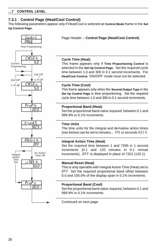
7.3.1 Control Page (Heat/Cool Control)The following parameters appear only if Heat/Cool is selected at Control Mode frame in the SetUp Control Page .
Page Header – Control Page (Heat/Cool Control) .
Cycle Time (Heat)This frame appears only if Time Proportioning Control isselected in the Set Up Control Page . Set the required cycletime between 1.0 and 300 in 0.1 second increments. ForHeat/Cool Control, 'ON/OFF' mode must not be selected.
Cycle Time (Cool)This frame appears only when the Second Output Type in theSet Up Control Page is time proportioning. Set the requiredcycle time between 1.0 and 300 in 0.1 second increments.
Proportional Band (Heat)Set the proportional band value required, between 0.1 and999.9% in 0.1% increments.
Time UnitsThe time units for the integral and derivative action times(see below) can be set to minutes MINS or seconds SECS.
Integral Action Time (Heat)Set the required time between 1 and 7200 in 1 secondincrements (0.1 and 120 minutes in 0.1 minuteincrements). OFF is displayed in place of 7201 (120.1).
Manual Reset (Heat)This is only operable with Integral Action Time (Heat) set toOFF. Set the required proportional band offset between0.0 and 100.0% of the display span in 0.1% increments.
Proportional Band (Cool)Set the proportional band value required, between 0.1 and999.9% in 0.1% increments.
Continued on next page.
…7 CONTROL LEVEL
CYCLE h5.0
OFF
t–untSSECS
ProP h100.0
50.0
IntegralActionTimeSet
Int. ActionTime Off
CYCLE c5.0
ProP c100.0
INtGrL h
MrSEt h
2nd O/P =
C–PrOP
ContrLPAGE
Time Proportioning
2nd O/P =
t–PrOP
CurrentProportioning
27
…7.3.1 Control Page (Heat/Cool Control)
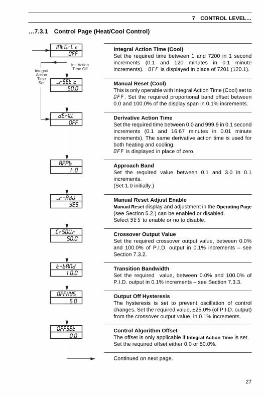
Integral Action Time (Cool)Set the required time between 1 and 7200 in 1 secondincrements (0.1 and 120 minutes in 0.1 minuteincrements). OFF is displayed in place of 7201 (120.1).
Manual Reset (Cool)This is only operable with Integral Action Time (Cool) set toOFF. Set the required proportional band offset between0.0 and 100.0% of the display span in 0.1% increments.
Derivative Action TimeSet the required time between 0.0 and 999.9 in 0.1 secondincrements (0.1 and 16.67 minutes in 0.01 minuteincrements). The same derivative action time is used forboth heating and cooling.OFF is displayed in place of zero.
Approach BandSet the required value between 0.1 and 3.0 in 0.1increments.(Set 1.0 initially.)
Manual Reset Adjust EnableManual Reset display and adjustment in the Operating Page(see Section 5.2.) can be enabled or disabled.Select YES to enable or no to disable.
Crossover Output ValueSet the required crossover output value, between 0.0%and 100.0% of P.I.D. output in 0.1% increments – seeSection 7.3.2.
Transition BandwidthSet the required value, between 0.0% and 100.0% ofP.I.D. output in 0.1% increments – see Section 7.3.3.
Output Off HysteresisThe hysteresis is set to prevent oscillation of controlchanges. Set the required value, ±25.0% (of P.I.D. output)from the crossover output value, in 0.1% increments.
Control Algorithm OffsetThe offset is only applicable if Integral Action Time is set.Set the required offset either 0.0 or 50.0%.
Continued on next page.
7 CONTROL LEVEL…
OFF
MrSEt c50.0
IntegralActionTimeSet
Int. ActionTime Off
OFF
50.0
APPb1.0
YES
10.0
OFFHYS5.0
OFFSEt0.0
INtGrL c
dErIV
Mr–AdJ
CrSOVr
t–bANd
28
7.3.2 Calculating the Crossover Value – Fig 7.3The crossover value is calculated from the expression:
Crossover Value = 100Gh/Gc + 1
Where Gh/Gc is the ratio of the two output driver gains.
The most common method for determining the Gh/Gc term is by using 'nameplate' values fromthe heat/cool device(s).
Example – if a heat/cool application can produce a maximum of 1.5kW and absorb 0.75kW:
Output Gain Ratio = 1.50.75
= 2
Crossover Value = 1002 + 1
= 33.3%
7.3.3 Calculating the Transition Bandwidth Value – Fig. 7.3The Transition Bandwidth is the percentage difference of the proportional band settings.
Example – if the proportional band settings for the heat output is 20% and for the cool outputis 25%:
Transition Bandwidth (%) = 25 – 2025
x 100
Transition Bandwidth = 20%
If the proportional band settings for both outputs are equal, the bandwidth is 0%. As a generalrule, the Transition Bandwidth should not exceed 30%.
…7 CONTROL LEVEL
29
8 PROFILE OPERATION
8.1 Profile Operating PageThis only appears if the Profile Enable frame is set to on in the Profile Program Page – seeSection 4.1 in the Programming Guide. Parameters displayed in this page cannot be modified.
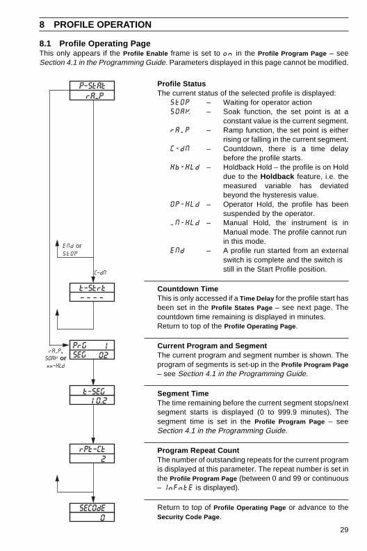
Profile StatusThe current status of the selected profile is displayed:
StOP – Waiting for operator actionSOAK – Soak function, the set point is at a
constant value is the current segment.rAMP – Ramp function, the set point is either
rising or falling in the current segment.C-dN – Countdown, there is a time delay
before the profile starts.Hb-HLd – Holdback Hold – the profile is on Hold
due to the Holdback feature, i.e. themeasured variable has deviatedbeyond the hysteresis value.
OP-HLd – Operator Hold, the profile has beensuspended by the operator.
MN-HLd – Manual Hold, the instrument is inManual mode. The profile cannot runin this mode.
ENd – A profile run started from an externalswitch is complete and the switch isstill in the Start Profile position.
Countdown TimeThis is only accessed if a Time Delay for the profile start hasbeen set in the Profile States Page – see next page. Thecountdown time remaining is displayed in minutes.Return to top of the Profile Operating Page .
Current Program and SegmentThe current program and segment number is shown. Theprogram of segments is set-up in the Profile Program Page– see Section 4.1 in the Programming Guide.
Segment TimeThe time remaining before the current segment stops/nextsegment starts is displayed (0 to 999.9 minutes). Thesegment time is set in the Profile Program Page – seeSection 4.1 in the Programming Guide.
Program Repeat CountThe number of outstanding repeats for the current programis displayed at this parameter. The repeat number is set inthe Profile Program Page (between 0 and 99 or continuous– InFntE is displayed).
Return to top of Profile Operating Page or advance to theSecurity Code Page .
021
t–SEG10.2
– – – –
rAMP,SOAK orxx–HLd
C–dN
2
SECOdE0
PrGSEG
rPt–Ct
t–Strt
rAMPP–StAt
ENd orStOP
30
…8 PROFILE OPERATION
8.2 Profile States PageThe Profile States Page is only present if the Profile Enable frame is set to on in the ProfileProgram Page – see Section 4.1 in the Programming Guide.
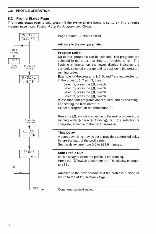
Page Header – Profile States .
Advance to the next parameter.
Program SelectUp to four programs can be selected. The programs areselected in the order that they are required to run. Theflashing character on the lower display indicates thecurrently selected program and its position in the programrunning order.Example – if the programs 1, 3, 5, and 7 are required to runin the order 1, 5, 7 and 3, then:
Select 1, press the switchSelect 5, press the switchSelect 7, press the switchSelect 3, press the switch
If less than four programs are required, end by selectingand storing the terminator 'W'.Select a program, or the terminator 'W'.
Press the switch to advance to the next program in therunning order (character flashing), or if the selection iscomplete, advance to the next parameter.
Time DelayA countdown time may be set to provide a controlled delaybefore the start of the profile run.Set the delay time from 0.0 to 999.9 minutes.
Start Profile Runno is displayed when the profile is not running.Press the switch to start the run. The display changesto YES.
Advance to the next parameter if the profile is running orreturn to top of Profile States Page .
Continued on next page.
PrOFLEStAtES
HOLd
-------NextPage
Profile notrunning
Profilerunning
1 5 7 3
SelectionComplete
20.0
noStArt
PrOGrM
tM–dLY
no
YES
31
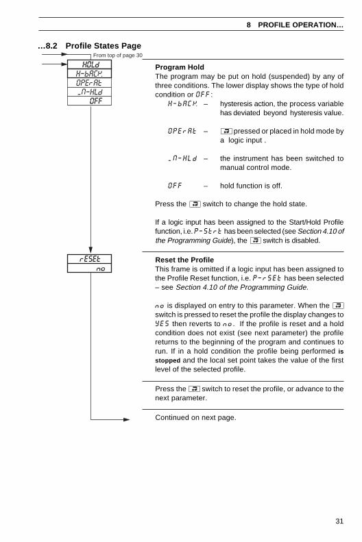
Program HoldThe program may be put on hold (suspended) by any ofthree conditions. The lower display shows the type of holdcondition or OFF:
H–bACK – hysteresis action, the process variablehas deviated beyond hysteresis value.
OPErAt – pressed or placed in hold mode bya logic input .
MN–HLd – the instrument has been switched tomanual control mode.
OFF – hold function is off.
Press the switch to change the hold state.
If a logic input has been assigned to the Start/Hold Profilefunction, i.e. P–Strt has been selected (see Section 4.10 ofthe Programming Guide), the switch is disabled.
Reset the ProfileThis frame is omitted if a logic input has been assigned tothe Profile Reset function, i.e. P–rSEt has been selected– see Section 4.10 of the Programming Guide.
no is displayed on entry to this parameter. When theswitch is pressed to reset the profile the display changes toYES then reverts to no. If the profile is reset and a holdcondition does not exist (see next parameter) the profilereturns to the beginning of the program and continues torun. If in a hold condition the profile being performed isstopped and the local set point takes the value of the firstlevel of the selected profile.
Press the switch to reset the profile, or advance to thenext parameter.
Continued on next page.
…8.2 Profile States Page
8 PROFILE OPERATION…
HOLdFrom top of page 30
OFF
H–bACKOPErAt
norESEt
MN–HLd
32
…8 PROFILE OPERATION
…8.2 Profile States Page
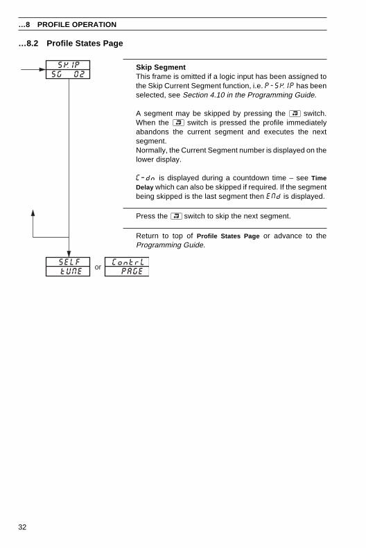
Skip SegmentThis frame is omitted if a logic input has been assigned tothe Skip Current Segment function, i.e. P-SKIP has beenselected, see Section 4.10 in the Programming Guide.
A segment may be skipped by pressing the switch.When the switch is pressed the profile immediatelyabandons the current segment and executes the nextsegment.Normally, the Current Segment number is displayed on thelower display.
C–dn is displayed during a countdown time – see TimeDelay which can also be skipped if required. If the segmentbeing skipped is the last segment then ENd is displayed.
Press the switch to skip the next segment.
Return to top of Profile States Page or advance to theProgramming Guide.
SG 02SKIP
tUNESELF
PAGEContrL
or
PRODUCTS & CUSTOMER SUPPORT
A Comprehensive Product RangeAnalytical Instrumentation
• TransmittersOn-line pH, conductivity, and dissolved oxygentransmitters and associated sensing systems.
• SensorspH, redox, selective ion, conductivity anddissolved oxygen.
• Laboratory InstrumentationpH and dissolved oxygen meters and associatedsensors.
• Water AnalyzersFor water quality monitoring in environmental,power generation and general industrialapplications including: pH, conductivity, ammonia,nitrate, phosphate, silica, sodium, chloride,fluoride, dissolved oxygen and hydrazine.
• Gas AnalyzersZirconia, paramagnetic, infrared, thermalconductivity.
Controllers & Recorders• Controllers
Digital display, electronic, pneumatic. Discretesingle-loop and multi-loop controllers which canbe linked to a common display station, processcomputer or personal computer.
• RecordersCircular and strip-chart types (single and multi-point) for temperature, pressure, flow and manyother process measurements.
Electronic Transmitters• Smart & Analog Transmitters
For draft, differential, gauge and absolutepressure measurement. Also, liquid level andtemperature.
• I to P Converters and Field Indicators
Flow Metering• Magnetic Flowmeters
Electromagnetic, insertion type probes andwatermeters.
• Turbine Flowmeters
• Wedge Flow Elements
• Mass Flow MetersTransmitters, sensors, controllers and batch/display units.
Level Control• Submersible, Capacitance & Conductivity.
Pneumatic Instrumentation• Transmitters
• Indicating Controllers
• Recording Controllers
Customer SupportABB Instrumentation provides a comprehensive aftersales service via a Worldwide Service Organization.Contact one of the following offices for details on yournearest Service and Repair Centre.
United KingdomABB Instrumentation LimitedTel: +44 (0)1480 475321Fax: +44 (0)1480 470787
United States of AmericaABB Automation Inc.Instrumentation DivisionTel: +1 215-674-6000Fax: +1 215-674-7183
ItalyABB Instrumentation SpATel: +39 (0) 344 58111Fax: +39 (0) 344 58278
Client Warranty
Prior to installation, the equipment referred to inthis manual must be stored in a clean, dryenvironment, in accordance with the Company'spublished specification. Periodic checks must bemade on the equipment's condition.
In the event of a failure under warranty, thefollowing documentation must be provided assubstantiation:
1. A listing evidencing process operation andalarm logs at time of failure.
2. Copies of operating and maintenance recordsrelating to the alleged faulty unit.

IM/C
300–
OG
Issu
e 6
The Company's policy is one of continuous productimprovement and the right is reserved to modify theinformation contained herein without notice.
© ABB 1999 Printed in UK (10.99)
ABB Instrumentation LtdSt. NeotsCambs.England, PE19 3EUTel: +44 (0) 1480 475321Fax: +44 (0) 1480 217948
ABB Automation Inc.Instrumentation Division125 E. County Line RoadWarminster, PA 18974 USATel: +1 215-674-6000Fax: +1 215-674-7183
ABB Instrumentation SpA22016 LennoComoItalyTel: +39 (0) 344 58111Fax: +39 (0) 344 58278


