Committee representation The Industry Standards Committee on Road Vehicles (ISC L) under whose authority this Malaysian Standard was developed, comprises representatives from the following organisations: Automobile Association of Malaysia Department of Environment Department of Standards Malaysia Jabatan Pengangkutan Jalan Malaysia Malaysia Automotive Institute Malaysian Automotive Association Malaysian Automotive Components Parts Manufacturers Association Malaysian Institute of Road Safety Research Ministry of Domestic Trade, Co-operatives and Consumerism Ministry of International Trade and Industry Motorcycle and Scooter Assemblers and Distributor Association of Malaysia PUSPAKOM Sdn Bhd Road Safety Department Malaysia Polis Diraja Malaysia SIRIM Berhad (Secretariat) Universiti Putra Malaysia Universiti Teknologi Malaysia Co-opted members: Motosikal dan Enjin Nasional Sdn Bhd PERODUA Manufacturing Sdn Bhd Perusahaan Otomobil Nasional Sdn Bhd The Technical Committee on Braking, Suspension Systems and Wheel Assembly which supervised the development of this Malaysian Standard consists of representatives from the following organisations: Jabatan Pengangkutan Jalan Malaysia Malaysian Automotive Association Malaysian Institute of Road Safety Research Mintye Industries Bhd. PERODUA Manufacturing Sdn Bhd Perusahaan Otomobil Nasional Berhad Polis Diraja Malaysia PUSPAKOM Sdn Bhd Sapura Industrial Berhad SIRIM Berhad (Advanced Materials Research Centre) SIRIM Berhad (Secretariat) SIRIM QAS International Sdn Bhd Universiti Teknikal Malaysia Melaka Universiti Teknologi Malaysia The Working Group on Suspension System which developed this Malaysian Standard consists of representatives from the following organisations: APM Shock Absorbers Sdn Bhd KYB-UMW Sdn Bhd Malaysian Automotive Association Perusahaan Otomobil Nasional Sdn Bhd Sapura Technical Centre Sdn Bhd SIRIM Berhad (Secretariat) SIRIM QAS International Sdn Bhd Co-opt member: PERODUA Manufacturing Sdn Bhd
Foreword This Malaysian Standard was developed by the Working Group on Suspension System under the authority of the Industry Standards Committee on Road Vehicles. Compliance with a Malaysian Standard does not of itself confer immunity from legal obligations.
Introduction This Malaysian Standard is formulated to ensure safe and quality products with regards to suspension strut and telescopic shock absorbers. In order to completely validate the product before being introduced into the market, both component level as well as in combination as a system fitted to the vehicle need to be evaluated. This standard is specifically to ensure the mechanical strength of these components only, therefore it is recommended that the below Malaysian Standards are to be used in combination to ensure overall safe dynamic behaviour of the vehicle. 1. MS 1944: Part 1, Passenger cars - Test track for a severe lane-change manoeuvre -
Part 1: Double lane-change;
2. MS 1944: Part 2, Passenger cars - Test track for a severe lane-change manoeuvre - Part 2: Obstacle avoidance; and
3. M S 1944: Part 3, Passenger car - Test track for a severe lane-change manoeuvre - Part 3: Vehicle preparation prior to testing.
Road vehicles - Suspension strut and telescopic shock absorbers strength and durability
1 Scope This Malaysian Standard specifies the strength and durability requirements for suspension strut and telescopic shock absorbers of M1 and N1 category. NOTE. For category M1 and N1, refer to MS 1822. 2 Normative references The following normative references are indispensable for the application of this standard. For dated references, only the edition cited applies. For undated references, the latest edition of the normative reference (including any amendments) applies. MS 1822, Classification and definition of power-driven vehicles and trailers JIS Z 2371, Methods of salt spray testing 3 Terms and definitions For the purposes of this standard, the following terms and definitions apply. 3.1 Suspension strut 3.1.1 ABS sensor bracket An integral mounting bracket to mount the ABS sensor wire harness to the strut. 3.1.2 brake hose bracket An integral mounting bracket to mount the brake hose to the strut. 3.1.3 knuckle bracket A bracket used to mount the complete hub assembly with the strut. 3.1.4 spring seat A supporting metal pan for the coil spring, normally welded, press fitted or can be a threaded collar mounted to the body of the strut. 3.1.5 stabiliser bar bracket An integral mounting bracket to mount the stabiliser bar to the strut.
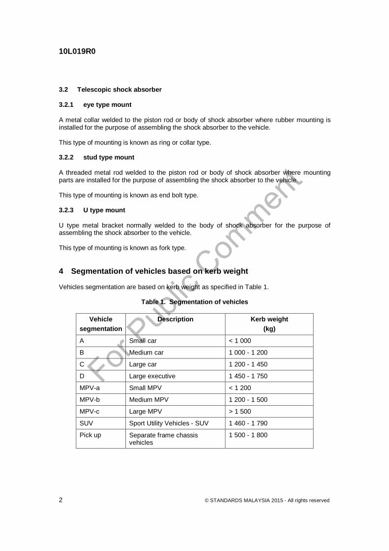
3.2 Telescopic shock absorber 3.2.1 eye type mount A metal collar welded to the piston rod or body of shock absorber where rubber mounting is installed for the purpose of assembling the shock absorber to the vehicle. This type of mounting is known as ring or collar type. 3.2.2 stud type mount A threaded metal rod welded to the piston rod or body of shock absorber where mounting parts are installed for the purpose of assembling the shock absorber to the vehicle. This type of mounting is known as end bolt type. 3.2.3 U type mount U type metal bracket normally welded to the body of shock absorber for the purpose of assembling the shock absorber to the vehicle. This type of mounting is known as fork type. 4 Segmentation of vehicles based on kerb weight Vehicles segmentation are based on kerb weight as specified in Table 1.
5 Requirements 5.1 Welding strength for suspension strut Suspension strut for each vehicle segmentation shall fulfil the specified minimum welding strength as in Table 2.
Table 2. Welding strength for suspension strut
Vehicle segmentation
Spring seat
force, min. (kN)
Stabiliser bracket force, min. (kN)
Brake hose
bracket force, min. (kN)
ABS sensor bracket
force, min. (kN)
Knuckle bracket force, min.
(kN)
Single bracket
Double brackets
A 19.6 14.7 9.8 9.8 29.4 19.6
B 19.6 14.7 9.8 9.8 29.4 19.6
C 19.6 14.7 9.8 9.8 58.8 29.4
D 19.6 14.7 9.8 9.8 58.8 29.4
MPV-a 19.6 14.7 9.8 9.8 29.4 19.6
MPV-b 19.6 14.7 9.8 9.8 29.4 19.6
MPV-c 19.6 14.7 9.8 9.8 - 29.4
SUV 19.6 14.7 14.7 14.7 58.8 29.4
Pick up 28 - - - - - NOTE. For pick up segment, shock absorber is using telescopic type without any bracket attachments. In some cases, spring seat may not be available. This segment is likely subjected to heavy duty usage.
5.2 Welding strength for telescopic shock absorber Telescopic shock absorber for each vehicle segmentation shall fulfil the specified minimum welding strength as in Table 3.
Table 3. Welding strength (tensile and impact) for telescopic shock absorber
Vehicle segmentation
Welding tensile strength, F, min
(kN)
Welding impact strength, F, min (N.m)
Eye type Stud type U type Eye type Stud type U type A 24.5 24.5 24.5 250 250 340
B 24.5 24.5 24.5 250 250 340
C 24.5 24.5 24.5 250 250 340
D 24.5 24.5 24.5 250 250 340
MPV-a 24.5 24.5 24.5 250 250 340
MPV-b 24.5 24.5 24.5 250 250 340
MPV-c 24.5 24.5 24.5 250 250 340
SUV 29.4 24.5 29.4 290 290 340
Pick up 29.4 24.5 29.4 290 290 - NOTE. 1. The welding strength value can be applied to upper and bottom part. 2. 1 N.m = 1 Joule
5.3 Surface treatment Materials used for surface treatment shall be free from substances of environmental concern (SOC) as listed below: a) mercury; b) lead; c) hexavalent chromium; and d) cadmium. 5.4 Corrosion Coating and painting shall fulfil minimum of 300 h salt spray test. For judgement method, agreement between manufacturer and customer shall be consulted. 5.5 Oil seal durability test Suspension strut and telescopic shock absorber shall fulfil the specified requirements as in Table 4.
± 25 0.3 1 x 10⁶ a) Reduction rate of damping force at piston speed 0.3 m/s shall be 25 % maximum both rebound and compression sides. b) No oil leakage, wear and internal parts/valves damage.
C and D
2 500 (ST) 150 (SA)
± 25 0.3 1 x 10⁶
MPV-a and MPV-b
2 500 (ST) 150 (SA)
± 25 0.3 1 x 10⁶
MPV-c 2 900 (ST) 150 (SA)
± 25 0.3 1 x 10⁶
SUV and pick up
2 900 (ST) 150 (SA)
± 25 0.3 1 x 10⁶
Legend: ST = Suspension strut SA = Telescopic shock absorber
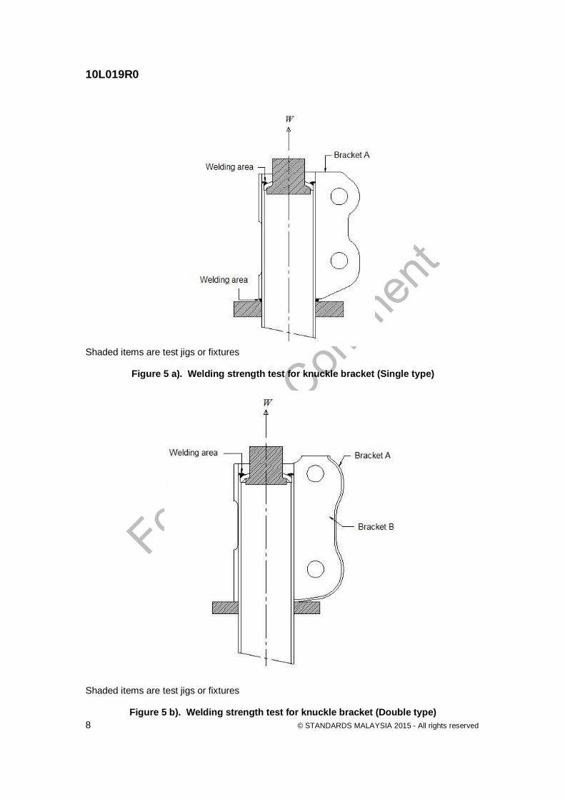
6 Test methods 6.1 Welding strength for suspension strut 6.1.1 The purpose of the test is to determine the strength of welding brackets and spring seat of suspension strut. 6.1.2 Test procedure and recording of result The following test procedure and evaluation method are applicable to all items in Table 2 that are subjected to welding strength test. a) Mount the test piece to an appropriately design test jig which is able to apply load to the
direction prescribed in Figures 1, 2, 3, 4, 5 a) and 5 b). b) Apply the appropriate load, W accordingly at the average speed rate 10 mm/min as
shown in Figures 1, 2, 3, 4, 5 a) and 5 b) until the test piece deforms or breaks. Record the peak value achieved.
c) Evaluation of the test items shall be according to the values in the Table 2.
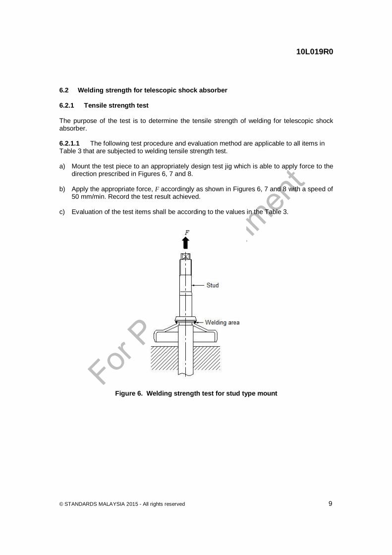
6.2 Welding strength for telescopic shock absorber 6.2.1 Tensile strength test The purpose of the test is to determine the tensile strength of welding for telescopic shock absorber. 6.2.1.1 The following test procedure and evaluation method are applicable to all items in Table 3 that are subjected to welding tensile strength test. a) Mount the test piece to an appropriately design test jig which is able to apply force to the
direction prescribed in Figures 6, 7 and 8. b) Apply the appropriate force, F accordingly as shown in Figures 6, 7 and 8 with a speed of
50 mm/min. Record the test result achieved. c) Evaluation of the test items shall be according to the values in the Table 3.
Figure 6. Welding strength test for stud type mount
Figure 7. Welding strength test for eye type mount
Figure 8. Welding strength test for U type mount
6.2.2 Impact strength test The purpose of the test is to determine the impact strength of welding for telescopic shock absorber. 6.2.2.1 The impact force requirements shall refer to Table 3. However, setting methods depend on individual test machines and operators shall adjust accordingly.
The following test procedure and evaluation method are applicable to all items that are subjected to welding impact strength test. a) Mount the test piece to an appropriately design test jig which is able to withstand the
impact force, F to the direction prescribed in Figures 9, 10 and 11. b) Record the test result achieved. c) Evaluation of the test items shall be according to the values in the Table 3.
6.5 Oil seal durability test 6.5.1 The purpose of the test is to determine the oil seal life span of strut and telescopic shock absorbers. 6.5.2 The following test procedure and evaluation method are applicable to all items that are subjected to oil seal durability test. a) Measure and record the damping force before the oil seal endurance test as shown in
5.5.2. b) Fit the upper part of test item on the equipment. c) Set the piston rod stroke to the middle position which is half of its piston rod length
exposed from its body, L. Refer to Figure 15. d) Fit the lower part. e) Apply a constant lateral side load, F to the rod guide of test item according to Table 4. f) Adjust the temperature to be in the range of (70 ± 10) C. Cooling fan can be used to
maintain constant temperature. g) Continuously test the test item up to the specified number of cycle as according to
Table 4. h) Check and observe for any abnormal oil leakages at an interval of 50 000 cycles. The test
shall be stopped if any abnormalities are observed. i) Measure and record damping force of test item after the completion of the oil seal
endurance test as according to 5.5.2. j) Check and observe for any abnormal wear on the functional parts by disassembling and
examining the item after the test. Refer Table 4 for evaluation criteria.
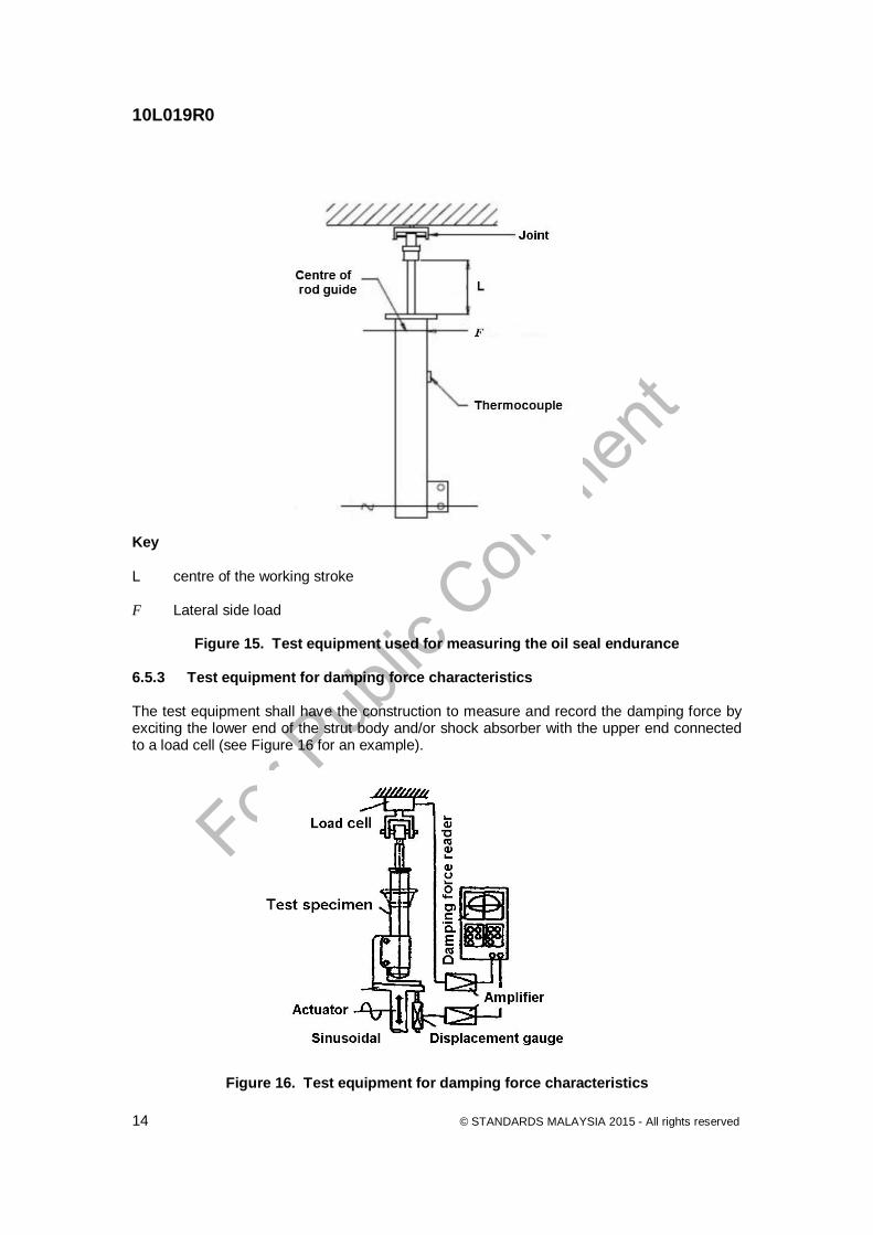
Key L centre of the working stroke F Lateral side load
Figure 15. Test equipment used for measuring the oil seal endurance 6.5.3 Test equipment for damping force characteristics The test equipment shall have the construction to measure and record the damping force by exciting the lower end of the strut body and/or shock absorber with the upper end connected to a load cell (see Figure 16 for an example).
Figure 16. Test equipment for damping force characteristics
Acknowledgements Members of Technical Committee on Braking, Suspension Systems and Wheel Assembly Name Organisation Prof Dr Sha'ri Mohd Yusof (Chairman) Universiti Teknologi Malaysia Ms Nik Aida Azura Nik Md Salleh (Secretary) SIRIM Berhad Mr Mohd Fairuz Izani/Mr Azzaharin Alias Jabatan Pengangkutan Jalan Malaysia Mr Zulhaidi Mohd Jawi@Said Mr Wee Soon Huat/ Ms Goh Ju Lee Mr Qamarul Bahrain Mohd Badiuzzaman
Malaysian Institute of Road Safety Research Mintye Industries Bhd. PERODUA Manufacturing Sdn Bhd
Ms Raja Zaidatul Akhma Raja Fuaddin Perusahaan Otomobil Nasional Sdn Bhd (Testing and Homologation)
Mr Jasni Dewa Perusahaan Otomobil Nasional Sdn Bhd (Vehicle Engineering Division)
ASP Afzanizar Ahmad Polis Diraja Malaysia Mr Zainol Arifen Said PUSPAKOM Sdn Bhd Mr Kamaluddin Abdul Aziz/ Mr Azmul Fadhli Kamaruzaman
Sapura Industrial Berhad
Mr Mohd Faizar Mustafa SIRIM QAS International Sdn Bhd Members of Working Group on Suspension System Name Organisation Mr Stephen Oo (Chairman) Malaysian Automotive Association Ms Nik Aida Azura Nik Md Salleh (Secretary) SIRIM Berhad Mr Hoh Kim Yong APM Shock Absorbers Sdn Bhd Mr Khalili Zulkifli Independent Mr Azmi Mohd Tahir KYB-UMW Sdn Bhd Mr Azrifin Amin Perusahaan Otomobil Nasional Sdn Bhd Mr Mohd Faizar Mustafa SIRIM QAS International Sdn Bhd Mr Muhamad Nurizan Fakir Sapura Technical Centre Sdn Bhd
Co-opted member Mr Qamarul Bahrain Mohd Badiuzzaman PERODUA Manufacturing Sdn Bhd