47
Comments on injector linac for INDUS‐II RRCAT, Indore 11 March, 2010 T. Higo, KEK

Comments on injector linac for INDUS‐II
RRCAT, Indore
11 March, 2010
T. Higo, KEK

Thoughts and discussions today• 700MeV or higher / 40m in total
– Minimum requirement
– Can be based on KEKB
– Higher injection rate with multi‐bunch operation?
– Or anything other to consider
• 2.5GeV full‐energy injection– Pros on ring acceptance and injection rate and others
– Cost , Space ?
2010/3/11 2Higo at RRCAT

Existing TW linac examplesKEK‐B (S) ATF (S) KEKB (C) XFEL(C)
E GeV 8 1.3 test 8
Acc str freq. Band S S C C
Acc str length m 2 3 1 1.8
# acc str ~4*8*8 17+2 5 2*4*16
Eacc MV/m 20 26 40 35
Acc length/ klystron m 8 6 4 3.6
P_kly MW 41 60 40 50
P_kly / Lacc MW/m 5 10 10 14
These show the feasibility of S‐band linac at 30MV/m and C‐band at 40MV/m?
2010/3/11 3Higo at RRCAT

Rough idea for today’s discussion
• Robust and probably cheap solution– S‐band long acc structure
• Worthwhile to consider – Energy booster section with higher frequency?
– C‐band at 40MV/m level is feasible
– X‐band at 40~60MV/m is to be considered
2010/3/11 Higo at RRCAT 4
Firm base at S‐band
• Most matured technology• Possibly most cheap as for accelerator
– Take advantage of medium mass production at various high energy linac
– But optimize design to further optimization pursuing cost, efeciency, etc.
• But big power is needed to go higher gradient to shorten linac
2010/3/11 Higo at RRCAT 5

Let us start with KEKB linac unit configuration
Klystron
Acc str (1)
Acc str (2)
Acc str (3)
Acc str (4)
SLED
Tunnel
Kly gallery
2010/3/11 6Higo at RRCAT
Modulator
Power source
Pulse compressor
Transport line
Distribution to multi acc sections

KEKB 8‐GeV injector linac “nominal”
• Linac: 1GeV/sector * 8 sectors– 512m acceleration
• Sector: 160MeV * 8 units– 64m acceleration
• RF Unit: 40MeV * 4 acc structures– klystron SLED 4 acc structures– 41MW klystron– 8m acceleration at 20MV/m
Starting point for design of GeV‐scale linac
2010/3/11 7Higo at RRCAT

Structure parameters• Pseudo CG section
– 5 types (A‐E) of 2m section for HOM cancellation to suppress BBU
• Typical parameters of type‐C– 2a = 24~20mm
– τ = 0.333– Rs = 54~62 MΩ/m– Vg/c = 1.75~0.92%
2010/3/11 8Higo at RRCAT

Possible optimization with CG
2m section nominal
3m section with higher power
3m section with extending smaller a
Z
Vg/c
2m smaller aperture choice
2010/3/11 9Higo at RRCAT
Smaller aperture higher shunt impedance.Higher power enable to contain larger aperture.
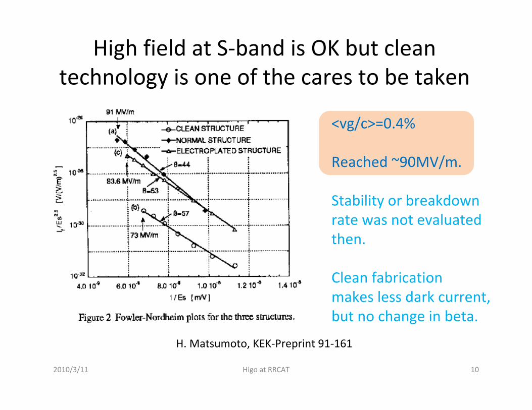
High field at S‐band is OK but clean technology is one of the cares to be taken
H. Matsumoto, KEK‐Preprint 91‐161
<vg/c>=0.4%
Reached ~90MV/m.
Stability or breakdown rate was not evaluated then.
Clean fabrication makes less dark current, but no change in beta.
2010/3/11 10Higo at RRCAT
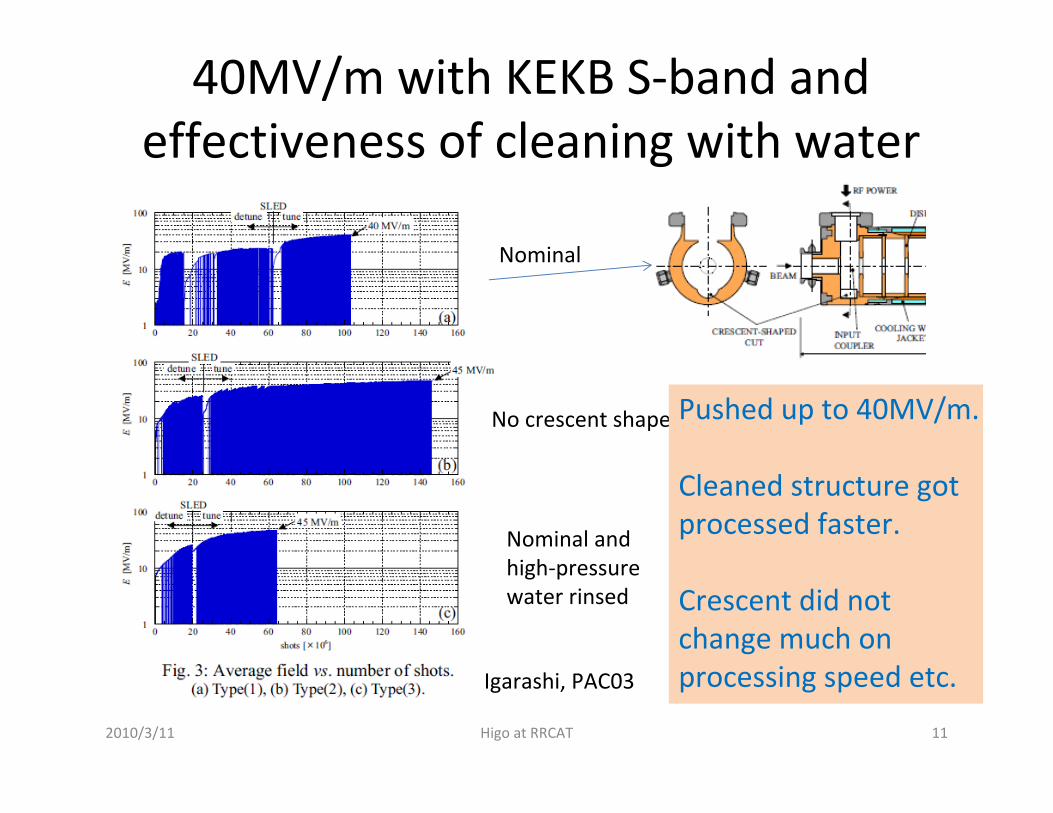
40MV/m with KEKB S‐band and effectiveness of cleaning with water
No crescent shape
Nominal
Nominal and high‐pressure water rinsed
Igarashi, PAC03
Pushed up to 40MV/m.
Cleaned structure got processed faster.
Crescent did not change much on processing speed etc.
2010/3/11 11Higo at RRCAT

Dark current evolution in general and surface quality variation
Yamaguchi,
Processing makesless and less dark current.
smaller field enhancement factor, beta value2010/3/11 12Higo at RRCAT

Pulse compression for high peak power
To obtain higher peak power with 4 microsec and Q0=105
Beam integration in accelerator section makes acceleration voltage gain by a factor 2.
Structure output
SLED output
2010/3/11 13Higo at RRCAT
Well established

>700MeV design with based on half KEKB unit
• KEKB 2m*4 acc str with SLED 9.6m in total
• Half KEKB unit 2m * 2 acc str 5m• 42MW kly SLED 2 acc str• 27.5 MV/m 110MeV/unit• 7 units 770 MeV / 35m
• 2a=24.4~20.4mm , τ=0.333, vg/c=1.7~0.9%
2010/3/11 14Higo at RRCAT

Some natural improvement with 3m
• ATF 3m*2 acc str with SLED
• ATF unit 3m * 2 acc str 7m• 42MW kly SLED 2 acc str• 23.5 MV/m 144MeV/unit• 5 units 720 MeV / 35m
• a=12.6~9.5mm, τ=0.45, vg/c=2.2~0.9%
2010/3/11 15Higo at RRCAT

Possibility to increase gradient
• Smaller aperture– If beam stability is satisfied
• Check single bunch loading
• Longer structure– Mechanically not preferable
• Higher Q pulse compressor
2010/3/11 16Higo at RRCAT

Possibility to increase intensity
• Multi‐bunch– Energy equalization with
• SLED phase control?
• With multi‐bunch energy compensator– Different frequency?
– Phase / amplitude modulation without SLED
2010/3/11 17Higo at RRCAT

Possibility to reduce cost
• Take established technology and configuration
• Explore some room for further optimization on efficiency
• Take higher gradient with higher frequency with the same average power for modulator
2010/3/11 18Higo at RRCAT

Possibility to use C‐band• Present SuperKEKB(C)
– Double # acc str / klystron than KEKB(S)• 2 acc str / klystron
– Keep klystron peak power the same 42MW– Reduce klystron pulse width by half 2microsec– Double the acc field 40MV/m 20MV/m– Beam hole aperture 2a=14.5 ~ 12.5 ~ 10.5
• Comparing to KEK(S) 2a=24.4~20.4• How about
– Single‐bunch beam stability?– Energy spread?
2010/3/11 19Higo at RRCAT
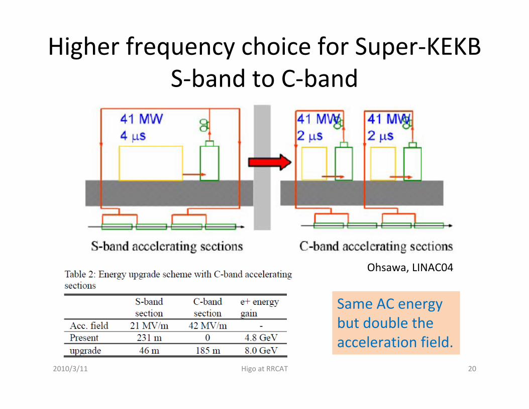
Higher frequency choice for Super‐KEKB S‐band to C‐band
Ohsawa, LINAC04
Same AC energy but double the acceleration field.
2010/3/11 20Higo at RRCAT
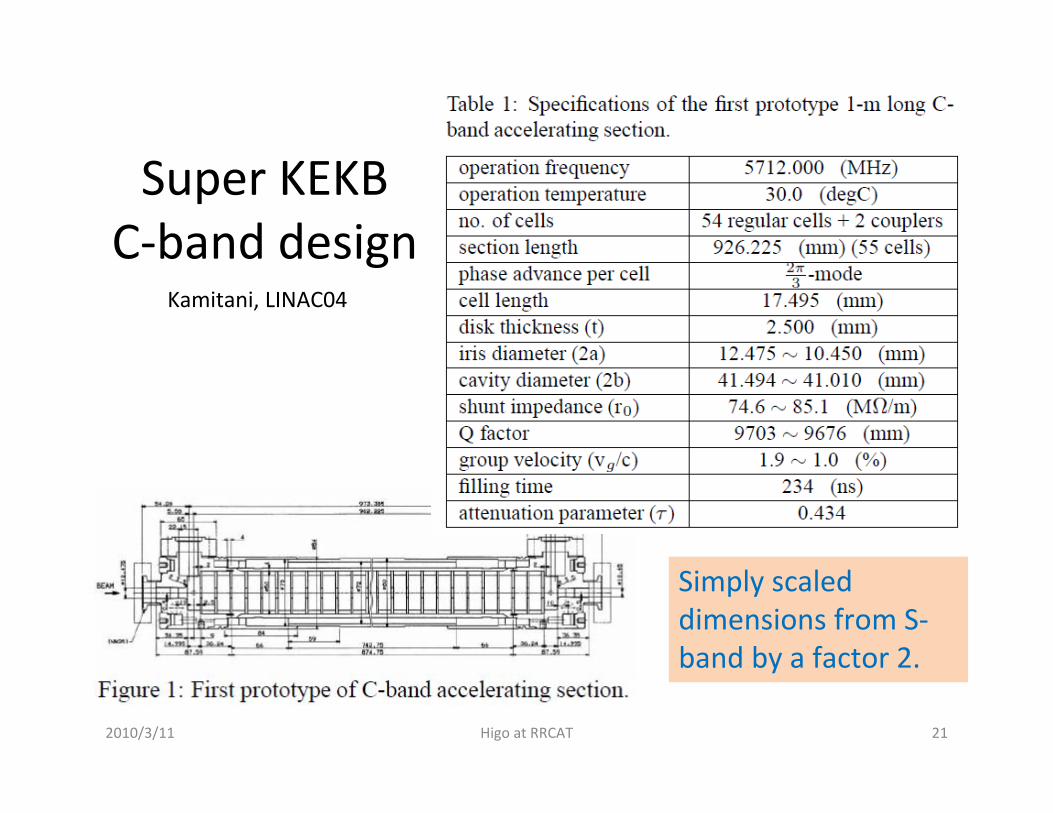
Super KEKB C‐band design
Kamitani, LINAC04
Simply scaled dimensions from S‐band by a factor 2.
2010/3/11 21Higo at RRCAT
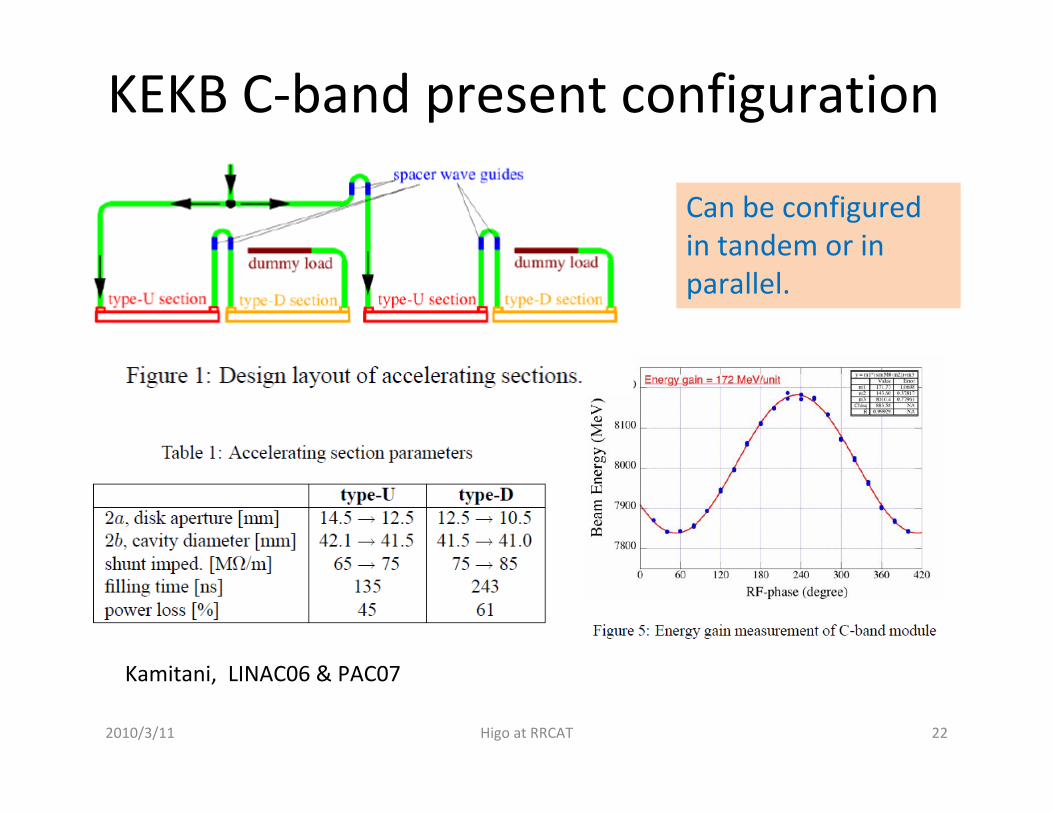
KEKB C‐band present configuration
Kamitani, LINAC06 & PAC07
Can be configured in tandem or in parallel.
2010/3/11 22Higo at RRCAT

Processing to higher field with C‐band
Kamitani, LINAC04
Easy processing up to 40MV/m in 10 days.
2010/3/11 23Higo at RRCAT

Problem in coupler iris
Kamitani, LINAC04Damage was speculated to be due to thin iris between coupler cell and waveguide
2010/3/11 24Higo at RRCAT

C‐band coupler design evolution
Sugimura, PAC05
(a)
Thin Thick Thick and round
Breakdowns at coupler were reduced.
2010/3/11 25Higo at RRCAT

X‐band case, 0th order estimation
• Based on 60cm‐long high‐phase advance structure– 2a=7.5~8mm– 60cm– 5π/6 mode– Tf~100ns– 50MW input ( 22MW)– 60MV/m ( 40MV/m)– 72MeV / unit ( 96MeV/unit)– 1.5m ( 3m) / unit – 35 RF units ( 26 units)– 50m ( 78m) / 2.5 GeV
2010/3/11 Higo at RRCAT 26

X‐band possible system
2010/3/11 Higo at RRCAT 27
50MW , ~1microsec
X2.5 in power
Transmission lossA few ~ 20%
50MW, 200ns
50MW, 200ns
60MV/m, 100ns beam
72MeV / 1.5m ~ 50MV/m in reality 50m for 2.5GeV?
60cm acc str 1 60cm acc str 2

Technical feasibility• Klystron
– SLAC 50MW XL‐4, KEK PPM exist• Pulse compression
– Delay line type or cavity type > X2.5 feasible• Transport
– TE01, etc. low‐loss mode, OK in practice• Accelerating structure
– High phase advance structure, confirmed• Load
– Various candidate exist
2010/3/11 Higo at RRCAT 28

KEK PPM klystron
2010/3/11 Higo at RRCAT 29

PPM klystron performance
2010/3/11 Higo at RRCAT 30
0
20
40
60
80
100
120
0 200 400 600 800 1000 1200 1400 1600
Pulse Shotening of PPM#4 Klystron
Power [MW]
Pulse width [ns]
1/Tpulse
0.0
10.0
20.0
30.0
40.0
50.0
60.0
70.0
80.0
90.0
350.0 400.0 450.0 500.0 550.0C athode V oltage (kV )
Power (MW) / Eff.
P ow er
Efficiency

22m PC for 300ns being constructed at KEK Nextef
2010/3/11 Higo at RRCAT 31
22m delay line

Cavity type compressor developed now by CERN
2010/3/11 Higo at RRCAT 32
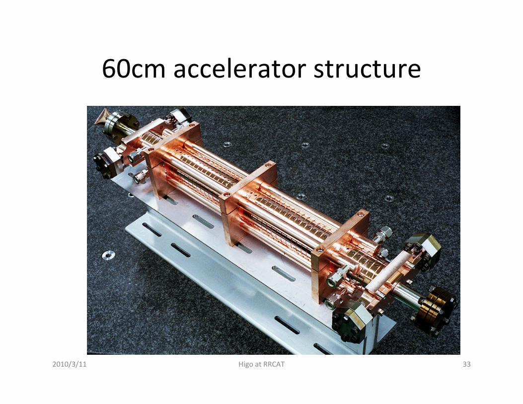
60cm accelerator structure
2010/3/11 Higo at RRCAT 33

2010/3/11 Higo at RRCAT 34
10-8
10-7
10-6
10-5
10-4
10-3
60 70 80 90 100 110 120
加速管放電頻度 (BD/pulse/m)BDR_KX01 60cm 400nsBDR_KX03 60cm 400nsBDR_T53VG3MC 100nsBDR_H75VG4S18 150ns BDR_T18_#2 252nsBDR_T18_#2 400nsKX03 fitKX01 fit
Eacc (MV/m)
Feasible field levelAccelerator structure breakdown rate
0.6m
0.2m
0.5m0.75m
50~65 …. 90~100 MV/m is feasiblein 0.5~1m size X‐band accelerator structure.

Possible unit configuration
KEKB (S) KEKB (C) X(1) X(2) X(3)
Freq MHz 2856 5712 11424 11424 11424
Acc str length m 3 2 0.6 0.6 1.3
# acc str / unit 4 2 2 4 1
Eacc MV/m 20 40 60 40
Acc length/ unit m 8 4 1.2 2.4 1.3
P_kly MW 42 42 50 50
PC Yes / No Y Y Y Y Y
Linac length m 150 80 50 50
2010/3/11 35Higo at RRCAT

Choice of even higher frequency?X‐band or higher
• X‐band (within a practical choice)– NLCTA acceleration in usual operation ~50MV/m?– LCLS bunch compressor– High gradient studies for > several thousand hours
• NLCTA (SLAC), Nextef (KEK)• >65MV/m for 0.6m section• ~100MV/m for 0.2m section
• 30GHz (beyond present‐day choice)– CTF2, CTF3 only brief test from my view point– Need power source idea
2010/3/11 36Higo at RRCAT

Issues to be considered other than high gradient ∵ stronger wake field
• Short‐range wake field– Single bunch emittance– Alignment of beam aperture– Bunch length– Energy spread
• Long‐range wake field– Multi‐bunch BBU HOM suppression– Multi‐bunch energy compensation– Alignment SBPM
2010/3/11 37Higo at RRCAT
These should be estimated, but straightforward because all calculable.

Short range transverse wake field
38
})/()/1(1{4)( 00400 ssExpss
ascZsWT −+−=
π
17.1
38.079.1
00 169.0,377L
gasZ =Ω=
402)(a
cZsWs T π
=∂∂
Initial slope;
Transverse wake field for NLC structure;
10.0 0.2 0.4 0.6 0.8 1.0
50
100
150
200
a=3mm
a=4mm
a=5mm
s [mm]
WT [V
/pC/mm/m
]
Transverse wake field for NLC.
0
0
100
200
Linear slope andstrong dependence on “a”!
2010/3/11 Higo at RRCAT

Aperture will be increased by taking higher phase advance
Medium‐damped and detuned for HOM suppression.High phase advance (150 deg/cell) for large aperture.
If this scales simply to C‐band, it becomesLs=1.2m, 2a=18 in average, 66MW 35MV/m
To realize larger aperture without reducing shunt impedance much.
2010/3/11 39Higo at RRCAT

Long‐range wake field for HOMDetuning by varying (a,t)
40
(a,t) distribution along structure
Dipole modedistribution in frequency and kick factor
Contour of dipole mode frequency vs (a,t)
2010/3/11 Higo at RRCAT

Long‐range wake field for HOMWeak damping by manifold
12000
14000
16000
18000
20000
0 30 60 90 120 150 180
RDDS1 DispersionFd1(97-102)Fd2(97-102)Mahifold(97-102)
Phase shift / cell
2nd dipole
Manifold
1st dipole
Example of middle cells of RDDS1
Avoided crossing due to the coupling of cavity dipole mode and manifold mode.
Example cell shape
Manifold Cell
2010/3/11 41Higo at RRCAT

DS and DDS scheme
• Initial fast damping with detuning
• Truncation makes recurrence
• Weak damping suppress the recurrence
• Interleaving among structures helps.
42
• These design were established in X‐band but applicable to S or C.
2010/3/11 Higo at RRCAT

Actual DDS example
43
Input / output waveguide
HOM damping waveguide
Detuned cells
Manifold to carry HOM to outside
This shows DDS example.DS becomes much simpler configuration,
almost the same as usual CG structure!2010/3/11 Higo at RRCAT

Alignment by Structure BPM
44
0
100
200
300
400
500
-400 -300 -200 -100 0 100 200 300 400
15 GHz Dipole Power Scan
Parabolic Fit
Measured Power
Sign
al P
ower
(au)
Beam Y Position (Microns)
Excited power
0
50
100
150
200
-400 -300 -200 -100 0 100 200 300 400
15 GHz Dipole Phase Scan
Measured Phase
Arctan(Y/27)
Phas
e (d
egre
es)
Beam Y Position (Microns)
Phase of excited fieldMeasured structure straightness
Power from manifold
Frequency filtered
Phase and amplitude
Frequency‐to‐position
Straightness measure
2010/3/11 Higo at RRCAT
SBPM gives a few micron precision misalighment info w.r.t. beam

Do we choose higher frequency?• Worthwhile to consider design based on higher frequency
• It depends on beam specification is required– intensity, bunch shape, single/multi, ….
• Methods to suppress wake field can be applied also at lower frequency design
• The availability of the power source may determine the frequency choice, in addition to the cost
2010/3/11 Higo at RRCAT 45

Frequency choice • S‐band ~20MV/m linac is already in operation
– With more power, 30~40MV/m seems available– Well matured technology
• C‐band ~40MV/m linac is realized– Technology mostly established
• X‐band ~65MV/m or higher is proved– Potential to higher field operation– Power source and components are to be improved for higher
field• Determine with estimating
– Required beam intensity and pattern– Final energy and available space– Total cost including infrastructure and needed developments
with manpower from lab.
2010/3/11 Higo at RRCAT 46

Conclusion
• Cost effective
• Robust
• Well established at somewhere
• Then take S‐band design– With some improvement on efficiency, cost, etc.
– By choosing optimized parameters
– With cares to safely reach ~50MV/m surface field
2010/3/11 Higo at RRCAT 47


