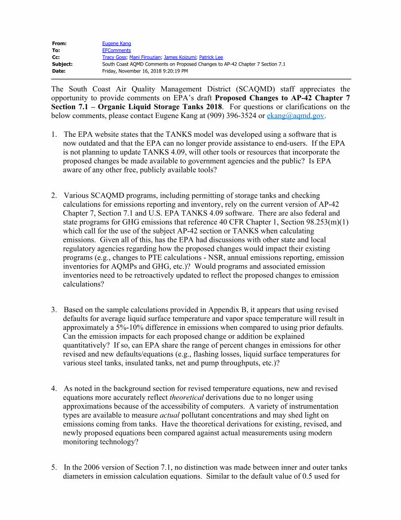
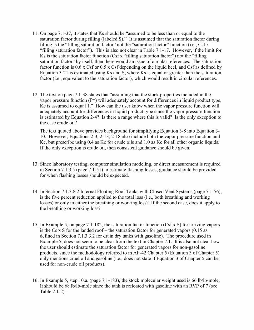
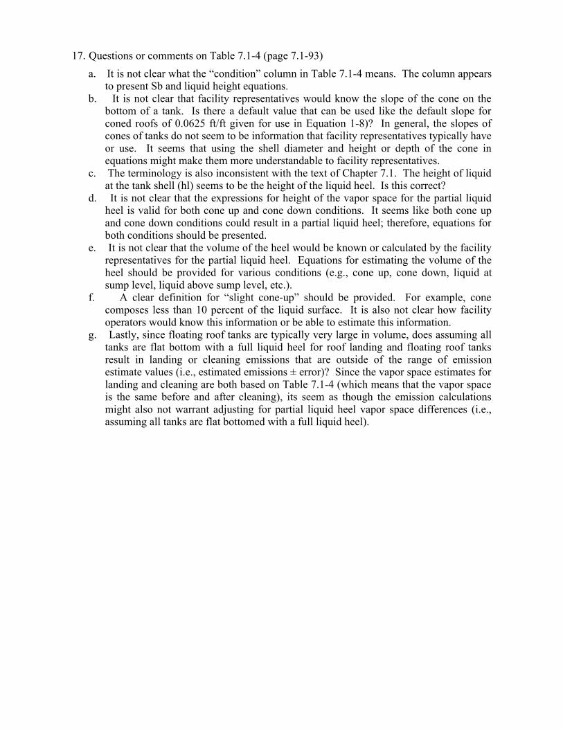
Comments Received For Revisions to Chapter 7 Section 7.1 Comment Period Closed November 26, 2018
Transcript
Comments Received For Revisions to Chapter 7 Section 71
Comment Period Closed November 26 2018
From Henkes John L (DEC)To EFCommentsCc Cronin Michael P (DEC)Subject Proposed Revisions to Chapter 7 Section 71- Organic Liquid Storage TanksDate Thursday July 26 2018 11417 PMAttachments image007png
image008png
To whom it may concern
Are there any conclusions as to the magnitude (+ or - )these changes will have on emissionestimation
Is there any guidance on past TANK 4 estimations Is there an urgency in recalculating emissionestimations from the current 71 or TANKS program
Thanks
John L Henkes PEEnvironmental Engineer II Bureau of Stationary Sources Division of Air Resources
New York State Department of Environmental Conservation
625 Broadway Albany NY 12233-3254P (518) 402-8403 | F (518) 402-9035 | JohnHenkesdecnygov
wwwdecnygov | |
From Chakrabarty Renu MTo EFCommentsSubject RE [chief] AP 42 Chapter 7 Section 71 Organic Liquid Storage Tanks Suggested UpdatesDate Wednesday August 01 2018 33644 PM
This response is to express that EPA has not provided sufficient characterization what the proposedchanges are and their expected impact to allow for informed comment and feedback
A summary of which pollutants are changing under which scenarios and how (increasing ordecreasing) would have provided the regulated community regulators and the public with sufficientinformation to determine whether additional review or comment would be warranted The absenceof any characterization of the changes and their expected impact leaves only those with specializedknowledge of the algorithms and operating scenarios and the resources to run them with any wayto know what the changes may be in order to then comment on them with credibility
Thank you Renu
Renu M Chakrabarty PEAssistant Director of Air Monitoring Laboratory amp Air ToxicsDivision of Air QualityWest Virginia Department of Environmental Protection
601 57th Street SECharleston WV 25304
Tel (304) 926-0499 ext 1246Fax (304) 926-0499
From CHIEF Info ltinfochiefepagovgt Sent Wednesday July 25 2018 305 PMTo Measurement Policy Group ltchieflistsepagovgtSubject [chief] AP 42 Chapter 7 Section 71 Organic Liquid Storage Tanks Suggested Updates
AP 42 Section 71 utilizes methodologies developed by the American Petroleum Institute(API) for estimating air emissions from organic liquid storage tanks It also containsdetailed descriptions of typical varieties of such tanks including horizontal vertical andunderground fixed roof tanks and internal and external floating roof tanks
Since the last time EPA revised AP 42 Section 71 there have been many updates andadditions to the methodologies described throughout the section Collectively API andEPA have worked together to propose necessary revisions to the emissions estimationsmethodologies for liquid storage tanks Information pertaining to this action andsupporting documentation can be accessed at the following link httpswwwepagovair-
From Wells - CDPHE DaleTo EFComments Emmett Malone - CDPHE Kevin Briggs Rebecca Simpson Darla Potter Tom Moore
jgrantrambollcomSubject proposed revisions to Chapter 7 Section 71 of AP-42Date Tuesday August 14 2018 41234 PM
7135 Flashing Loss is a new section on estimating flashing emissions The section refers topressurized liquid sampling but does not describe itnor how to analyze a pressurized liquidsample Pressurized liquid sampling is used to determine the rate of flash emissions and todesign controls but is fraught with problems
Noble Energy entered into a consent decree with EPA DOJ and the State of Colorado that inpart resulted in a study Pressurized Hydrocarbon Liquids Sampling and Analysis Study DataAssessment and Analysis Report that can be found here httpsjointagreementnoblecoloradocomwp-contentuploads201805SPL_PHLSA-Study_Final-Report_020718pdf
This document lists the difficulties in pressurized liquid sampling and analysis and makesrecommendations about how to perform and use the results of such sampling This workshould be integrated into AP42
--
Dale WellsModeling and Emission Inventory UnitTechnical Services ProgramAir Pollution Control DivisionColorado Department of Public Health and EnvironmentAPCD-TS-B14300 Cherry Creek Drive SouthDenver CO 80246-1530303-692-3237| dalewellsstatecousTo learn about ground-level ozone in Colorado visit our ozone webpage
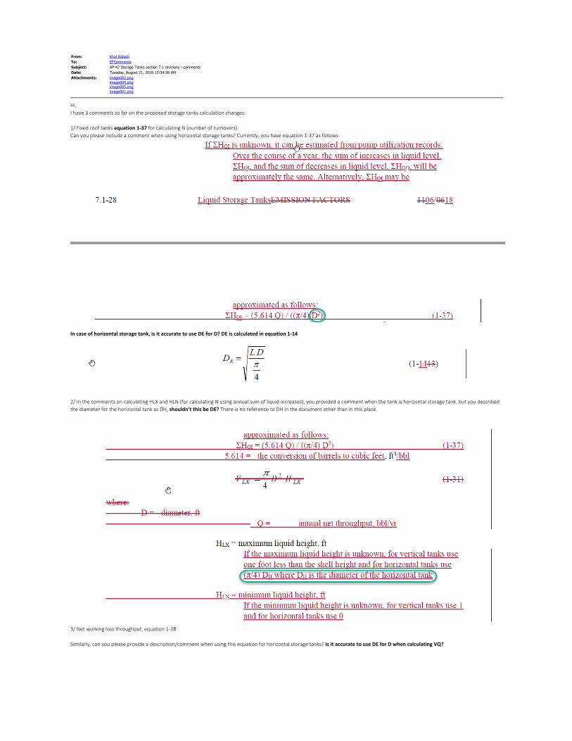
From Khal RabadiTo EFCommentsSubject AP-42 Storage Tanks section 71 revisions - commentsDate Tuesday August 21 2018 123438 AMAttachments image002png
image004pngimage005pngimage001png
HiI have 3 comments so far on the proposed storage tanks calculation changes 1 Fixed roof tanks equation 1-37 for calculating N (number of turnovers)Can you please include a comment when using horizontal storage tanks Currently you have equation 1-37 as follows
In case of horizontal storage tank is it accurate to use DE for D DE is calculated in equation 1-14
2 In the comments on calculating HLX and HLN (for calculating N using annual sum of liquid increases) you provided a comment when the tank is horizontal storage tank but you describedthe diameter for the horizontal tank as DH shouldnrsquot this be DE There is no reference to DH in the document other than in this place
3 Net working loss throughout equation 1-38 Similarly can you please provide a descriptioncomment when using this equation for horizontal storage tanks Is it accurate to use DE for D when calculating VQ
Regards
Khal Rabadi972 814-6529
From Janet L GreenbergTo EFCommentsSubject AP-42 Chapter 71Date Monday September 17 2018 114951 AM
We have these questions about the proposed revisions to AP-42 Chapter 71 for estimating emissionsfrom Tanks
1 There are mentions of using Distillate Flooding in the text accompanied by a statement that the vaporspace will equilibrate with the new liquid heel within 24 hours Is this time frame based upon a certaintank size That is if we are using distillate flooding with a relatively small tank is there a rule-of-thumb fora lesser time frame in which we could begin cleaning and presume that the vapor space has equilibrated
2 This statement is being removed regarding Constant Level TanksAlternatively a default turnover rate of four could be used based on data from these type tanksHas it been found to be unacceptable Was there originally a basis for the assumption of 4 turnoversbased upon calculation assumptions We have used this for many years for constant level wastewatersurge tanks and feel that the more extensive calculation procedure may be inappropriate for such tanks We typically choose a likely floating organic that could accumulate on top of the wastewater then assumethe vapor space is 100 saturated with that organic at 4 turnovers per year
From Madison MillerTo EFCommentsCc Phil MartinSubject Comment on Proposed Revisions to AP-42 Chapter 7Date Wednesday September 19 2018 52346 PMAttachments Comments on Proposed Revisions Chapter 7_1 (2)docx
To Whom It May Concern Attached please find comments on the Proposed Revisions to AP-42 Chapter 7 Section 71 from theOklahoma Department of Environmental Quality Please let me know if you have trouble with thedocument or need anything further Thank you Madison MillerSupervising Attorney Air Quality DivisionOffice of General CounselOklahoma Department of Environmental QualityOffice (918) 293-1625
Comments submitted by the Oklahoma Department of Environmental Quality (ODEQ)
September 19 2018
AP-42 Changes
The proposed revisions include emissions estimating methodologies for the following types of events and situations
bullLanding a floating roof
bullTank cleaning
bullTanks containing unstable liquids such as tanks which have air or other gases injected into the liquid (sparging) tanks storing liquids at or above their boiling point (boiling) or tanks storing liquids which contain gases that have the potential to flash out of solution (flashing)
bullVariable vapor space tanks
bullPressure tanks designed as closed systems without emissions to the atmosphere
bullTime periods shorter than one year
bullInternal floating roof tanks with closed vent systems
Additionally the proposed revisions include the following guidance
bullCase-specific liquid surface temperature determination
bullAdapting equations for heating cycles in fixed roof tanks
bullApplying Raoultrsquos Law to calculate the contribution of individual chemical species to the total emissions
bullWorked examples (Section 715)
Finally equations in Section 716 that have been used historically to obtain approximate values have been replaced with more accurate equations
From Henkes John L (DEC)To EFCommentsCc Cronin Michael P (DEC)Subject Proposed Revisions to Chapter 7 Section 71- Organic Liquid Storage TanksDate Thursday July 26 2018 11417 PMAttachments image007png
image008png
To whom it may concern
Are there any conclusions as to the magnitude (+ or - )these changes will have on emissionestimation
Is there any guidance on past TANK 4 estimations Is there an urgency in recalculating emissionestimations from the current 71 or TANKS program
Thanks
John L Henkes PEEnvironmental Engineer II Bureau of Stationary Sources Division of Air Resources
New York State Department of Environmental Conservation
625 Broadway Albany NY 12233-3254P (518) 402-8403 | F (518) 402-9035 | JohnHenkesdecnygov
wwwdecnygov | |
From Chakrabarty Renu MTo EFCommentsSubject RE [chief] AP 42 Chapter 7 Section 71 Organic Liquid Storage Tanks Suggested UpdatesDate Wednesday August 01 2018 33644 PM
This response is to express that EPA has not provided sufficient characterization what the proposedchanges are and their expected impact to allow for informed comment and feedback
A summary of which pollutants are changing under which scenarios and how (increasing ordecreasing) would have provided the regulated community regulators and the public with sufficientinformation to determine whether additional review or comment would be warranted The absenceof any characterization of the changes and their expected impact leaves only those with specializedknowledge of the algorithms and operating scenarios and the resources to run them with any wayto know what the changes may be in order to then comment on them with credibility
Thank you Renu
Renu M Chakrabarty PEAssistant Director of Air Monitoring Laboratory amp Air ToxicsDivision of Air QualityWest Virginia Department of Environmental Protection
601 57th Street SECharleston WV 25304
Tel (304) 926-0499 ext 1246Fax (304) 926-0499
From CHIEF Info ltinfochiefepagovgt Sent Wednesday July 25 2018 305 PMTo Measurement Policy Group ltchieflistsepagovgtSubject [chief] AP 42 Chapter 7 Section 71 Organic Liquid Storage Tanks Suggested Updates
AP 42 Section 71 utilizes methodologies developed by the American Petroleum Institute(API) for estimating air emissions from organic liquid storage tanks It also containsdetailed descriptions of typical varieties of such tanks including horizontal vertical andunderground fixed roof tanks and internal and external floating roof tanks
Since the last time EPA revised AP 42 Section 71 there have been many updates andadditions to the methodologies described throughout the section Collectively API andEPA have worked together to propose necessary revisions to the emissions estimationsmethodologies for liquid storage tanks Information pertaining to this action andsupporting documentation can be accessed at the following link httpswwwepagovair-
From Wells - CDPHE DaleTo EFComments Emmett Malone - CDPHE Kevin Briggs Rebecca Simpson Darla Potter Tom Moore
jgrantrambollcomSubject proposed revisions to Chapter 7 Section 71 of AP-42Date Tuesday August 14 2018 41234 PM
7135 Flashing Loss is a new section on estimating flashing emissions The section refers topressurized liquid sampling but does not describe itnor how to analyze a pressurized liquidsample Pressurized liquid sampling is used to determine the rate of flash emissions and todesign controls but is fraught with problems
Noble Energy entered into a consent decree with EPA DOJ and the State of Colorado that inpart resulted in a study Pressurized Hydrocarbon Liquids Sampling and Analysis Study DataAssessment and Analysis Report that can be found here httpsjointagreementnoblecoloradocomwp-contentuploads201805SPL_PHLSA-Study_Final-Report_020718pdf
This document lists the difficulties in pressurized liquid sampling and analysis and makesrecommendations about how to perform and use the results of such sampling This workshould be integrated into AP42
--
Dale WellsModeling and Emission Inventory UnitTechnical Services ProgramAir Pollution Control DivisionColorado Department of Public Health and EnvironmentAPCD-TS-B14300 Cherry Creek Drive SouthDenver CO 80246-1530303-692-3237| dalewellsstatecousTo learn about ground-level ozone in Colorado visit our ozone webpage
From Khal RabadiTo EFCommentsSubject AP-42 Storage Tanks section 71 revisions - commentsDate Tuesday August 21 2018 123438 AMAttachments image002png
image004pngimage005pngimage001png
HiI have 3 comments so far on the proposed storage tanks calculation changes 1 Fixed roof tanks equation 1-37 for calculating N (number of turnovers)Can you please include a comment when using horizontal storage tanks Currently you have equation 1-37 as follows
In case of horizontal storage tank is it accurate to use DE for D DE is calculated in equation 1-14
2 In the comments on calculating HLX and HLN (for calculating N using annual sum of liquid increases) you provided a comment when the tank is horizontal storage tank but you describedthe diameter for the horizontal tank as DH shouldnrsquot this be DE There is no reference to DH in the document other than in this place
3 Net working loss throughout equation 1-38 Similarly can you please provide a descriptioncomment when using this equation for horizontal storage tanks Is it accurate to use DE for D when calculating VQ
Regards
Khal Rabadi972 814-6529
From Janet L GreenbergTo EFCommentsSubject AP-42 Chapter 71Date Monday September 17 2018 114951 AM
We have these questions about the proposed revisions to AP-42 Chapter 71 for estimating emissionsfrom Tanks
1 There are mentions of using Distillate Flooding in the text accompanied by a statement that the vaporspace will equilibrate with the new liquid heel within 24 hours Is this time frame based upon a certaintank size That is if we are using distillate flooding with a relatively small tank is there a rule-of-thumb fora lesser time frame in which we could begin cleaning and presume that the vapor space has equilibrated
2 This statement is being removed regarding Constant Level TanksAlternatively a default turnover rate of four could be used based on data from these type tanksHas it been found to be unacceptable Was there originally a basis for the assumption of 4 turnoversbased upon calculation assumptions We have used this for many years for constant level wastewatersurge tanks and feel that the more extensive calculation procedure may be inappropriate for such tanks We typically choose a likely floating organic that could accumulate on top of the wastewater then assumethe vapor space is 100 saturated with that organic at 4 turnovers per year
From Madison MillerTo EFCommentsCc Phil MartinSubject Comment on Proposed Revisions to AP-42 Chapter 7Date Wednesday September 19 2018 52346 PMAttachments Comments on Proposed Revisions Chapter 7_1 (2)docx
To Whom It May Concern Attached please find comments on the Proposed Revisions to AP-42 Chapter 7 Section 71 from theOklahoma Department of Environmental Quality Please let me know if you have trouble with thedocument or need anything further Thank you Madison MillerSupervising Attorney Air Quality DivisionOffice of General CounselOklahoma Department of Environmental QualityOffice (918) 293-1625
Comments submitted by the Oklahoma Department of Environmental Quality (ODEQ)
September 19 2018
AP-42 Changes
The proposed revisions include emissions estimating methodologies for the following types of events and situations
bullLanding a floating roof
bullTank cleaning
bullTanks containing unstable liquids such as tanks which have air or other gases injected into the liquid (sparging) tanks storing liquids at or above their boiling point (boiling) or tanks storing liquids which contain gases that have the potential to flash out of solution (flashing)
bullVariable vapor space tanks
bullPressure tanks designed as closed systems without emissions to the atmosphere
bullTime periods shorter than one year
bullInternal floating roof tanks with closed vent systems
Additionally the proposed revisions include the following guidance
bullCase-specific liquid surface temperature determination
bullAdapting equations for heating cycles in fixed roof tanks
bullApplying Raoultrsquos Law to calculate the contribution of individual chemical species to the total emissions
bullWorked examples (Section 715)
Finally equations in Section 716 that have been used historically to obtain approximate values have been replaced with more accurate equations