48
12-135.4 • JULY, 2014 COMMERCIAL FIN TUBE RADIATION

12-135.4 • JULY, 2014
COMMERCIAL FIN TUBE RADIATION

2 12-135.4
Table of Contents PageModel Location . . . . . . . . . . . . . . . . . . . . . . . . . . . . . . . . . . . . . . . . . . . . . . . . . . . . . . . . . . . . . . . . . . . . . . . . 3Design Features - System Components/Accessories . . . . . . . . . . . . . . . . . . . . . . . . . . . . . . . . . . . . . . . . . . . 4Installation . . . . . . . . . . . . . . . . . . . . . . . . . . . . . . . . . . . . . . . . . . . . . . . . . . . . . . . . . . . . . . . . . . . . . . . . . . . . 6Sample Sizing Calculations . . . . . . . . . . . . . . . . . . . . . . . . . . . . . . . . . . . . . . . . . . . . . . . . . . . . . . . . . . . . . . . 8Correction Factors . . . . . . . . . . . . . . . . . . . . . . . . . . . . . . . . . . . . . . . . . . . . . . . . . . . . . . . . . . . . . . . . . . . . . 10Model Information (see Page 3) . . . . . . . . . . . . . . . . . . . . . . . . . . . . . . . . . . . . . . . . . . . . . . . . . . . . . . . . . . 12Specifications . . . . . . . . . . . . . . . . . . . . . . . . . . . . . . . . . . . . . . . . . . . . . . . . . . . . . . . . . . . . . . . . . . . . . . . . 47
TABLE OF CONTENTS / NOMENCLATURE
The Modine Breeze® AccuSpec is the fastest way to generate performance data based on actual job conditions . The Breeze® AccuSpec program is a web-based sizing and selection program . The program provides a series of step-by-step questions that allow for the easy configuration of Modine products . After a model has been configured, the program can generate Submittal Schedules, Submittal Data (including performance and dimensional drawings), and Specifications .
1,2,3 4,5,6 7,8 9 10,11,12ET EH MG DMP EL
1,2,3 - Enclosure Type (ET) S - Slope TopSP - TrimFin Slope TopR - Front and Top OutletF - Front OutletT - Top OutletTA - Top Outlet, Architectural GrilleSF - Slope Top Floor MountRF - Front and Top Outlet Floor MountP - Pedestal MountPA - Pedestal with Architectural GrillePS - Slope Top SecurityEM - Expanded Metal Element CoverFT - Flat Top Element CoverBIP - Bottom Inlet Panel
4,5,6 - Enclosure Height (EH) 001 - 1 Row Wide Pedestal002 - 2 Row Wide Pedestal003 - TrimFin Bottom Inlet Panel004 - 4" High Enclosure005 - Std Bottom Inlet Panel008 - 8" High Enclosure010 - 10" High Enclosure 012 - 12" High Enclosure014 - 14" High Enclosure018 - 18" High Enclosure024 - 24" High Enclosure
7,8 - Material Gauge (MG) 14 - 14 Gauge16 - 16 Gauge18 - 18 Gauge20 - 20 Gauge 9 - Damper (DMP) N - No DamperK - Knob Damper S - Security Damper
10,11,12 - Enclosure Length (EL)020 - 2' 0" Length 025 - 2' 6" Length 030 - 3' 0" Length 035 - 3' 6" Length 040 - 4' 0" Length 045 - 4' 6" Length 050 - 5' 0" Length 055 - 5' 6" Length 060 - 6' 0" Length 065 - 6' 6" Length 070 - 7' 0" Length 075 - 7' 6" Length 080 - 8' 0" Length
1,2,3 4,5,6 7,8 9 10,11,12TM TD FSP FSZ EL
1,2,3 - Tube Material (TM) CP - Copper 4,5,6 - Tube Diameter (TD) 075 - 0 .75" 100 - 1 .00" 125 - 1 .25" 7,8 - Fin Spacing (FSP) 34 - 34 fins/ft . 42 - 42 fins/ft . 50 - 50 fins/ft . 9 - Fin Size (FSZ) A - 2 .75" x 4 .25" Fin B - 2 .75" x 3 .25" Fin C - 4 .25" x 4 .25" Fin
10,11,12 - Element Length (EL)020 - 2' 0" Length 025 - 2' 6" Length 030 - 3' 0" Length 035 - 3' 6" Length 040 - 4' 0" Length 045 - 4' 6" Length 050 - 5' 0" Length 055 - 5' 6" Length 060 - 6' 0" Length 065 - 6' 6" Length 070 - 7' 0" Length 075 - 7' 6" Length 080 - 8' 0" Length 085 - 8' 6" Length 090 - 9' 0" Length 095 - 9' 6" Length 100 - 10' 0" Length 105 - 10' 6" Length 110 - 11' 0" Length 115 - 11' 6" Length 120 - 12' 0" Length
Enclosure Nomenclature Element Nomenclature

312-135.4
Model S Slope TopPage 14
Model SP Slope Top - Trimfin™
Page 12
Model T Top OutletPage 19
Model PS Security Slope TopPage 17
Model F Front OutletPage 22
Model R Front and Top OutletPage 25
Model TA Architectural Top OutletPage 28
Model SF Slope Top, Floor MountedPage 31
Model RF Front and Top Outlet, Floor MountedPage 33
Model P Pedestal StylePage 35
Model PA Architectural Pedestal StylePage 37
Model FT Flat Top Element CoverPage 40
Model EM Expanded Metal Element CoverPage 42
Model CP Bare Heating ElementPage 44
COMMERCIAL FIN TUBE RADIATION

4 12-135.4
Refer to Figure 4.2
Refer to numbered notes below
*
*
Refer toFigures 4.3 and 4.4
DESIGN FEATURES - SYSTEM COMPONENTS/ACCESSORIES
1 . Hanger strip provides an easy and sturdy method to properly align all components . Enclosure rests in the top V-bend of the hanger strip and positions the enclosure 1/16" from the wall and 3/16" above the top of the hanger strip so it is not visible, creating a clean, one piece appearance (see Figure 4 .2) . Standard hanger strip is 20 gauge aluminized steel in 4 and 8 foot lengths . Also available with full back panel .
2 . Enclosure/element support brackets with heating element cradle are suspended from the bottom V-bend of the hanger strip (see Figure 4 .2) . Infinite side to side location of brackets allows installation at strongest support points, such as wall studs . The hanger strip bears most of the weight, so only one wall fastener is required for each bracket . Holes are provided near the top of the bracket for installation of return pipe hanger (not available if using a damper in Note 7) .
3 . All element cradles rest on a full bearing nylon washer . There is no metal to metal contact and no noise from element expansion . Cradle and washer are fastened to bracket with a nylon rivet (see Figure 4 .3) .
4 . The double V-bend of the enclosure rests in the bottom V-bend of the enclosure support bracket (see Figure 4 .4) . A quarter turn latch (shown in locked position) allows insertion of the enclosure and securely holds it to the bracket . Latch is rotated by using a socket wrench on the Hex head bolt underneath .
5 . Copper tube/aluminum fin heating element is available in 3 tube diameters, 2 fin sizes, and 3 fin spacings .
6 . Enclosure sections are joined together utilizing a slip joint connection . Viewed from the interior of the enclosure, the slip joint is comprised of left and right hand spot welded clips (see Figure 4 .5) . Slip joint connections produce a barely noticeable joint on the exterior of the enclosure . Certain accessory parts, such as end caps, are also assembled with slip joint connections .
7 . Optional dampers are available with either exposed knob type damper operator or tamper-proof operator to prevent unauthorized damper operation or adjustment (see Figure 5 .1) . Damper blades are painted to match the enclosure . The damper blades are adjustable to any position between open and closed using a screw type operator . The damper blade assembly is factory installed and permanently attached to the enclosure . The damper operator mechanism is field installed .
Figure 4.1 - Typical System Components
See Note 1
See Note 2
Figure 4.3 - Element/Enclosure Support Assemblies
Figure 4.4 - Bottom Enclosure Support
Latch1/4 TurnLatch
Hex Bolt
Figure 4.5 - Enclosure Slip Fit Connections

512-135.4
DESIGN FEATURES - SYSTEM COMPONENTS/ACCESSORIES
8 . The bottom inlet panel is available to provide security cover to the open inlet at the bottom of the enclosure . It is fastened to the enclosure support brackets with a plastic expansion dart . See Figure 5 .2
9 . A wall support is used to support overlapping enclosure extensions at a wall . A 5" wide enclosure extension completes the gap between the enclosure and the wall . Fold over tabs at the bottom hold the extension firmly in place . Some accessory items, 12" wide extensions, 12" wide end enclosures are available with access doors . See Figure 5 .3 .
Figure 5.1 - Damper Operators
Figure 5.2 - Bottom Inlet Panel
Figure 5.3 - Enclosure Accessories
➅ ➃ ➄
➁➀
➂
Ref. No. Accessory Description ➀ ➁ Fit Type ➂ 1 Wall Support (R or L) 2 5" or 12" Wide Enclosure Extension (O) 2 12" Wide Enclosure Extension with Access Door (O) 3 12" or 18" Wide Valve Compartment (S) 4 90° Inside Corner (O) 5 90° Outside Corner (O) 6 12" Wide End Enclosure (S) (R or L) 6 12" Wide End Enclosure with Access Door (S) (R or L) 7 End Cap (S) (R or L) 8 135° Inside Corner (O) 9 135° Outside Corner (O)
➂ ➃ ➄ ➅ ➆➁➀
➀ Accessories constructed of 20 gauge CRS ➁ See Page 39 for Pedestal support and accessories➂ (O)=Overlapping, (S)=Slip, (R or L)=Right or Left Hand Configurations
135˚
135˚
135˚
135˚
➈➇
Figure 5.4 - Typical Enclosure Layout

6 12-135.4
1 . Create a level line at the required mounting height (recommended 4" clearance below element support bracket) . Fasten the hanger strip or hanger strip with full back panel at the desired height .
For styles SF or RF, a second line may be set on the floor to locate the floor angle location .
For style P, attach pedestal base to floor . Insert pedestal assembly and adjust height .
2 . Place the Enclosure Wall Support (EWS) on the hanger strip . Position the EWS to assure location directly over wall supports . Fasten each EWS with one fastener to a wall support . EWS placement is recommended every 3 feet . All EWS are equipped with a concealed enclosure lock . If the EWS has been ordered with integral element cradles, skip step 3 .
3 . When element pitch or other adjustment is required, a separate Element Support Assembly (ESA) is used . The ESA hooks into slots on the EWS . For 12" high style S enclosure, the ESA must be located in the lowest slot to avoid element contact with the enclosure .
4 . Return Pipe hangers (RPH) are attached into holes on the upper portion of the EWS to accommodate return piping . RPH is not to be used in combination with a damper for styles S or SF enclosures .
5 . In the fin-tube element placement, position the cradle on the EWS to allow for expansion of the element .
INSTALLATION
2
3
1a
1b
5
4a 4b
If dampers are included, the operator must be pre-assembled prior to enclosure installation .

712-135.4
INSTALLATION
6 . The first enclosure section should be set in place as noted by the Room Schedule (style S is shown at right) . Engage the enclosure into the hanger strip, then into the bottom bend of the Enclosure Wall Support (EWS) . Once in place, secure the enclosure to the bracket with a quarter turn of the hex headed enclosure latch .
7 . Adjoining sections of enclosure can be added to the first by means of interlocking slip-joints . The male strip always faces to the left, the concealed female clip always right . Start enclosure slip-joints from the top before engaging the hanger strip and EWS . Enclosures may be tapped together to protect the edge of the adjoining enclosure . As with the first enclosure, all other enclosures should be secured to the EWS by a quarter-turn of the built-in enclosure latch .
8 . Enclosure End Caps terminate enclosure when not running wall-to-wall and join to enclosures with concealed slip-joints . Each end cap adds to the overall length of fin-tube enclosures . End Caps with access door are also available . For fin-tube covers, EM and FT end caps overlap .
9 . Valve Compartments have concealed interlocking slip-joints to mate up with enclosures to provide valve access within an enclosure run . Locate as directed on Room Schedule .
10 . Enclosure extensions overlap enclosures and make up
length differences when running to a wall . Place extension over enclosure, then bend tabs to secure the extension to the bottom of the enclosure .
11 . Inside or Outside corners allow an enclosure run to continue around a corner . Corners overlap enclosures to make up length difference between walls . Corners have fold-over tabs . Place corner over enclosure, then bend tabs to secure the corner to the bottom of the enclosure .
6
7
9
10
11
8

8 12-135.4
Example 1 - Hot Water At Decreased FlowDetermine fin tube length required:
Conditions: Standard air temperature = 65°F Average water temperature = 200°F Water velocity = 1 .0 ft/sec Calculated heat loss of room = 20,000 Btu/hr .
Water Velocity Correction:A water velocity correction factor must be used if the water velocity is other than the 3 .0 ft/sec .
Heat Loss = Btu/hr if the water velocity is Correction Factor 3 .0 ft/sec
Water velocity correction factor for 1 .0 ft/sec = .957 (Refer to Table 9 .2 on page 9)
20,000 Btu/hr = 20,899 Btu/hr if the water 0 .957 velocity is 3 .0 ft/sec
Selection of Unit:A model ‘S’ Slope Top with an enclosure height of 12" and one row of 3/4" copper tube with aluminum fin size of 4-1/4" X 4-1/4" is desired .
Determine hot water ratings for desired tube and fin size (Refer to Table 15 .1 on page 15):
34 fins/ft = 1160 Btu/hr/ft 20,899 Btu/hr = 18 .0 linear ft . 1160 Btu/hr/ft
42 fins/ft = 1380 Btu/hr/ft 20,899 Btu/hr = 15 .1 linear ft . 1380 Btu/hr/ft
50 fins/ft = 1390 Btu/hr/ft 20,899 Btu/hr = 15 .0 linear ft . 1390 Btu/hr/ft
Example 2 - Hot Water, Air And Water Temperature Other Than StandardDetermine fin tube length required:
Conditions: Air temperature = 55°F Average water temperature = 210°F Water velocity = 3 .0 ft/sec (standard) Calculated heat loss of room = 20,000 Btu/hr .
Air And Water Temperature Correction:A correction factor must be used if the air and/or water temperatures other than standard conditions
Heat Loss = Btu/hr if the air and/or water Correction Factor temperature are not standard
Air and water correction factor = 1 .05 (Refer to Table 10 .2 on page 10)
20,000 Btu/hr = 19,048 Btu/hr if standard 1 .05 conditions
Selection of Unit:A model ‘S’ Slope Top with an enclosure height of 18" and two rows of 3/4" copper tube with aluminum fin size of 4-1/4" X 4-1/4" is desired .
Determine hot water ratings for desired tube and fin size (Refer to Table 15 .1 on page 15):
34 fins/ft = 2130 Btu/hr/ft 19,048 Btu/hr = 8 .9 linear ft ., 2130 Btu/hr/ft two rows
42 fins/ft = 2340 Btu/hr/ft 19,048 Btu/hr = 8 .1 linear ft ., 2340 Btu/hr/ft two rows
50 fins/ft = 2560 Btu/hr/ft 19,048 Btu/hr = 7 .4 linear ft ., 2560 Btu/hr/ft two rows
SAMPLE SIZING CALCULATIONS

912-135.4
Example 3 - Steam Systems At Non-Standard Air Temperature And Steam PressureDetermine fin tube length required:
Conditions: Air temperature = 55°F Steam pressure = 25 psi Calculated heat loss of room = 25,000 Btu/hr .
Air Temperature And Steam Pressure Correction:A model ‘S’ Slope Top with an enclosure height of 24" and three rows of 3/4" copper tube with aluminum fin size of 4-1/4" X 4-1/4" is desired .
A correction factor must be used for steam systems .
Standard Output X Correction Factor = Output at Conditions
34 fins/ft: 2630 Btu/hr/ft X 1 .59 = 4182 Btu/hr/ft
42 fins/ft: 2910 Btu/hr/ft X 1 .59 = 4627 Btu/hr/ft
50 fins/ft: 3160 Btu/hr/ft X 1 .59 = 5024 Btu/hr/ft
Refer to Table 15 .1 on page 15 for ratings Refer to Table 10 .3 on page 10 for correction factors
Selection of Unit:Determine fin tube length required:
34 fins/ft = 4182 Btu/hr/ft 25,000 Btu/hr = 6 .0 linear ft ., 4182 Btu/hr/ft three rows
42 fins/ft = 4627 Btu/hr/ft 25,000 Btu/hr = 5 .4 linear ft ., 4627 Btu/hr/ft three rows
50 fins/ft = 5024 Btu/hr/ft 25,000 Btu/hr = 5 .0 linear ft ., 5024 Btu/hr/ft three rows
Example 4 - Ethylene Glycol Solution CorrectionDetermine fin tube length required:
Conditions: Standard air temperature = 65°F Average solution temperature = 150°F Percent Ethylene Glycol = 50% Calculated heat loss of room = 20,000 Btu/hr .
Ethylene Glycol Correction:A model ‘S’ Slope Top with an enclosure height of 24" and one row of 3/4" copper tube with aluminum fin size of 4-1/4" X 4-1/4" is desired .
A correction factor must be used if an ethylene glycol solution is used .
Standard Output X Correction Factor = Output with 50% Glycol
34 fins/ft: 790 Btu/hr/ft X 0 .90 = 711 Btu/hr/ft
42 fins/ft: 860 Btu/hr/ft X 0 .90 = 774 Btu/hr/ft
50 fins/ft: 940 Btu/hr/ft X 0 .90 = 846 Btu/hr/ft
Refer to Table 15 .1 on page 15 for ratings Refer to Table 10 .1 on page 10 for correction factors
Selection of Unit:Determine fin tube length required:
34 fins/ft = 711 Btu/hr/ft 20,000 Btu/hr = 28 .1 linear ft . 711 Btu/hr/ft
42 fins/ft = 774 Btu/hr/ft 20,000 Btu/hr = 25 .8 linear ft . 774 Btu/hr/ft
50 fins/ft = 846 Btu/hr/ft 20,000 Btu/hr = 23 .6 linear ft . 846 Btu/hr/ft
SAMPLE SIZING CALCULATIONS

10 12-135.4
Entering Air Temperature °F Average Water Std . Temp . °F 45 55 65 70 75 80 85 90 95 100 100 0 .25 0 .19 0 .13 0 .11 0 .08 0 .06 110 0 .31 0 .25 0 .19 0 .16 0 .13 0 .11 0 .08 0 .06 120 0 .38 0 .31 0 .25 0 .22 0 .19 0 .16 0 .13 0 .11 0 .08 0 .06 130 0 .45 0 .38 0 .31 0 .28 0 .25 0 .22 0 .19 0 .16 0 .13 0 .11 140 0 .53 0 .45 0 .38 0 .34 0 .31 0 .28 0 .25 0 .22 0 .19 0 .16 150 0 .61 0 .53 0 .45 0 .42 0 .38 0 .34 0 .31 0 .28 0 .25 0 .22 160 0 .69 0 .61 0 .53 0 .49 0 .45 0 .42 0 .38 0 .34 0 .31 0 .28 170 0 .78 0 .69 0 .61 0 .57 0 .53 0 .49 0 .45 0 .42 0 .38 0 .34 180 0 .86 0 .78 0 .69 0 .65 0 .61 0 .57 0 .53 0 .49 0 .45 0 .42 190 0 .95 0 .86 0 .78 0 .73 0 .69 0 .65 0 .61 0 .57 0 .53 0 .49 200 1 .05 0 .95 0 .86 0 .82 0 .78 0 .73 0 .69 0 .65 0 .61 0 .57 210 1 .14 1 .05 0 .95 0 .91 0 .86 0 .82 0 .78 0 .73 0 .69 0 .65
Table 10.2 - Factors for Non-Standard Water Temperature and Air Temperature ➁
Entering Air Temperature °F Steam Pressure psi 45 55 65 70 75 80 85 90 100 110 0 .899 1 .22 1 .11 1 .00 0 .95 0 .90 0 .84 0 .80 0 .75 0 .65 0 .57 5 1 .34 1 .22 1 .11 1 .05 1 .00 0 .95 0 .90 0 .81 0 .75 0 .66 10 1 .45 1 .33 1 .22 1 .17 1 .11 1 .05 1 .00 0 .91 0 .85 0 .75 15 1 .55 1 .43 1 .31 1 .26 1 .20 1 .14 1 .09 1 .00 0 .94 0 .84 20 1 .63 1 .52 1 .40 1 .33 1 .28 1 .23 1 .17 1 .07 1 .02 0 .92 25 1 .71 1 .59 1 .47 1 .41 1 .36 1 .30 1 .25 1 .15 1 .09 0 .98 30 1 .78 1 .66 1 .54 1 .48 1 .42 1 .37 1 .31 1 .21 1 .15 1 .05 40 1 .91 1 .79 1 .66 1 .61 1 .54 1 .49 1 .43 1 .32 1 .27 1 .16 50 2 .02 1 .90 1 .77 1 .71 1 .65 1 .60 1 .54 1 .42 1 .37 1 .26 60 2 .10 2 .00 1 .87 1 .81 1 .75 1 .69 1 .63 1 .51 1 .47 1 .35 70 2 .20 2 .09 1 .95 1 .89 1 .83 1 .77 1 .71 1 .59 1 .55 1 .44 80 2 .27 2 .17 2 .03 1 .97 1 .91 1 .85 1 .80 1 .69 1 .63 1 .52 90 2 .36 2 .24 2 .11 2 .05 1 .98 1 .93 1 .87 1 .74 1 .70 1 .59 100 2 .43 2 .31 2 .18 2 .11 2 .05 2 .00 1 .94 1 .81 1 .77 1 .65 125 2 .59 2 .47 2 .33 2 .27 2 .21 2 .16 2 .10 1 .96 1 .92 1 .80 150 2 .73 2 .62 2 .47 2 .43 2 .35 2 .29 2 .23 2 .08 2 .05 1 .94 175 2 .86 2 .74 2 .60 2 .54 2 .47 2 .41 2 .35 2 .21 2 .17 2 .05 200 2 .95 2 .85 2 .71 2 .63 2 .58 2 .52 2 .47 2 .31 2 .29 2 .17
Table 10.3 - Factors for Non-Standard Steam Pressure and Air Temperature ➂
Figure 10.1 - Expansion in Copper Tubing
300°
200°
100°
0 1/2" 1" 1-1/2" 2" 2-1/2" 3" 3-1/2"ExPANSION-INCHES PER 100 LINEAR FEET
TEM
PER
ATU
RE
RIS
E °F
Copper
Average Water Temperature Factor
100 0 .15
110 0 .20
120 0 .26
130 0 .33
140 0 .40
150 0 .45
155 0 .49
160 0 .53
165 0 .57
170 0 .61
175 0 .65
180 0 .69
Table 10.1 - Converting AHRI Steam Ratings to Hot Water Ratings at Indicated Temperature ➀
Average Water Temperature Factor
185 0 .73
190 0 .78
195 0 .82
200 0 .86
205 0 .91
210 0 .95
215 1 .00
220 1 .05
225 1 .09
230 1 .14
235 1 .20
240 1 .25➀Multiply correction factor x 1 PSI steam rating to determine
Btu at actual water temperature rating .
➁Multiply correction factor x 1 PSI steam rating to determine Btu at non-standard water and air temperature .
➂Multiply correction factor x 1 PSI steam rating to determine Btu at non-standard steam pressure and air temperature .
CORRECTION FACTORS

1112-135.4
Enclosure Inlet Height
4" 3" 2" 1-1/2" 1" 3/4" 1/2" All Styles 1 .00 1 .00 0 .99 0 .97 0 .85 0 .63 0 .40
Ethylene Glycol Solution % Solution Temperature (°F) 20% 30% 40% 50% 60% 70% 80% 100 0 .99 0 .96 0 .93 0 .89 0 .85 0 .81 0 .76 150 0 .99 0 .96 0 .94 0 .90 0 .87 0 .83 0 .78 200 0 .99 0 .97 0 .94 0 .92 0 .88 0 .85 0 .81 250 0 .98 0 .96 0 .94 0 .92 0 .89 0 .86 0 .82
Table 11.1 - Ethylene Glycol Correction Factors ➀
Gallons Per Minute Copper Ft ./Sec . Correction Velocity 3/4" Dia . 1" Dia . 1-1/4" Dia . Factor 3 .0 5 .0 8 .5 12 .9 1 .000 2 .5 4 .2 7 .1 10 .7 0 .992 2 .0 3 .3 5 .7 8 .6 0 .984 1 .5 2 .5 4 .2 6 .4 0 .973 1 .0 1 .7 2 .8 4 .3 0 .957 0 .5 0 .8 1 .4 2 .1 0 .931 0 .25 0 .4 0 .7 1 .1 0 .905
Table 11.2 - Factors for Reduced G.P.M. and Velocity ➀
Table 11.3 - Factor for Enclosure Mounted Lower Than Recommended 4" Inlet Height ➀
➀ When inlet height is less than 4", use these Correction Factors to determine BTU at actual mounting height .
Enclosure Total Height 18" or less 19" 20" 21" 22" 23" 24" 25" 26" 27" 28" 29" 30" 32" 34" 36" or more S 1 .10 1 .09 1 .09 1 .08 1 .07 1 .07 1 .06 1 .05 1 .05 1 .04 1 .03 1 .03 1 .02 1 .01 1 .01 1 .00 R, F, FT, EM 1 .15 1 .14 1 .13 1 .12 1 .11 1 .10 1 .09 1 .08 1 .07 1 .06 1 .05 1 .04 1 .03 1 .02 1 .01 1 .00
Table 11.4 - Factors for Enclosure Mounted Higher Than Recommended 4" Inlet Height ➀
➀ When enclosures are mounted more than 4" above floor, use the following formula to determine BTU at actual mounting height .
➀ The factors in this table may be used only when the water flow rate through the finned tube unit is known and where the flow rate is less than three feet per second . To determine the output at less than three feet per second, multiply the AHRI Water Rating by the factor in this table which applies to the known flow rate .
Actual Mounting Height Factor = CORRECTION FACTOR Recommended Mounting Height Factor
EXAMPLE - S12
12 inch enclosure height + 4 inch inlet height = 16 inch recommended Mounting Height .Change to 12 inch enclosure height + 12 inch inlet height = 24 inch actual Mounting Height .
Factors from Table 11 .4:At 16 inches, factor = 1 .10 At 24 inches, factor = 1 .06Apply to formula: 1 .06 = CORRECTION FACTOR 1 .10
Correction Factor X Catalog Rating (BTU) = BTU at Actual Mounting Height .
➀ For Propylene Glycol solution correction factor, multiply Ethylene Glycol correction factor by 0 .95 .
CORRECTION FACTORS
If the unit is to be installed at a different height than recommended, the AHRI Rating shall be adjusted as follows:

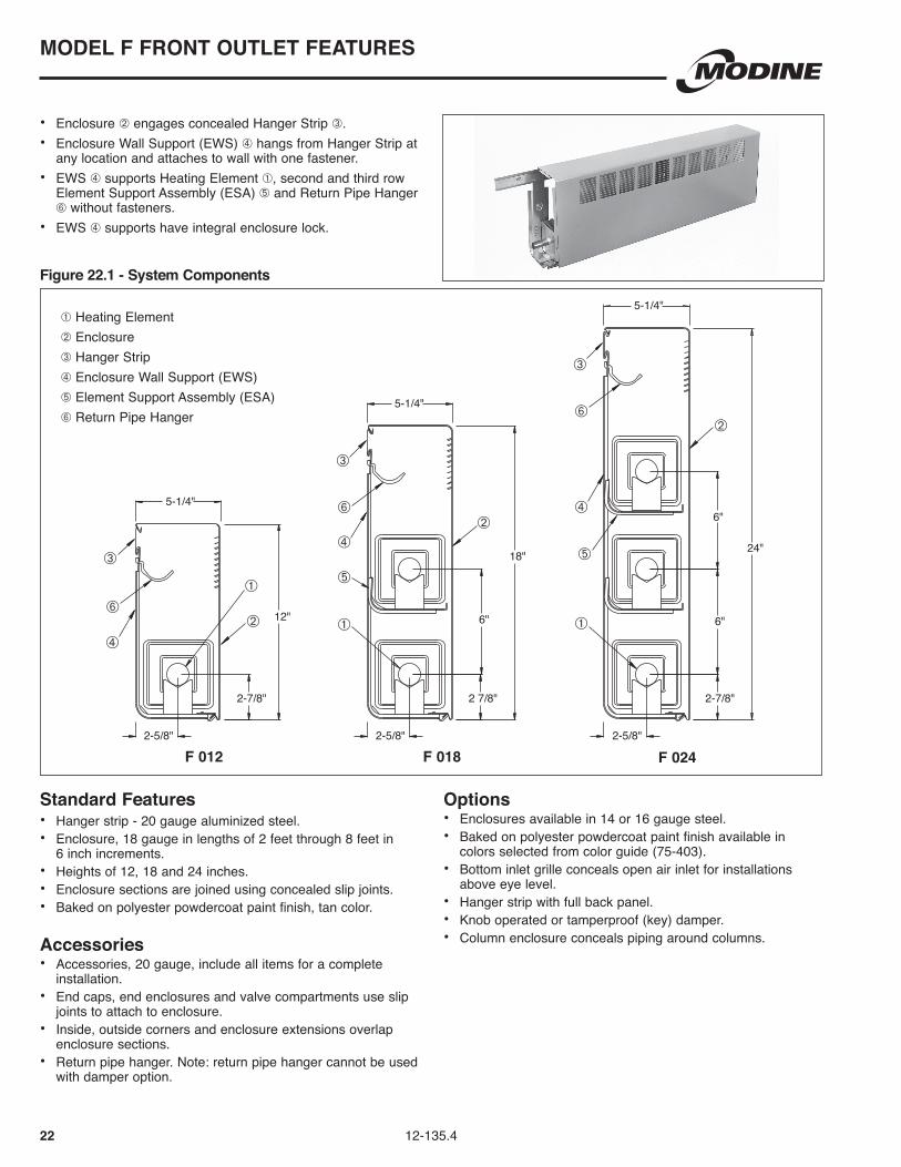
12 12-135.4
• Enclosure ➁ engages with concealed Hanger Strip ➂ .• Enclosure Wall Support (EWS) ➃ hangs from Hanger Strip at
any location and attaches to wall with one fastener .• EWS ➃ supports Heating Element ➀, second and third row
Element Support Assembly (ESA) ➄ and Return Pipe Hanger ➅ without fasteners .
• EWS ➃ supports have integral enclosure lock .
8"
3-5/8"
3-5/8"
10"
3-5/8"
14"
5"
2-9/16"
1-15/16"1-15/16"
2-9/16"
1-15/16"
2-9/16"
Standard Features• Hanger strip - 20 gauge aluminized steel .• Enclosure, 18 gauge in lengths of 2 feet through 8 feet in
6 inch increments .• Heights of 8, 10, and 14 inches .• Enclosure sections are joined using concealed slip joints .• Baked on polyester powdercoat paint finish, tan color .
Accessories• Accessories, 18 gauge, include all items for a complete
installation .• End caps, end enclosures and valve compartments use slip
joints to attach to enclosure .• Inside, outside corners and enclosure extensions overlap
enclosure sections .• Return pipe hanger . Note: return pipe hanger cannot be used
with damper option .
Options• Enclosures available in 14 or 16 gauge steel .• Baked on polyester powdercoat paint finish available in
colors selected from color guide (75-403) .• Bottom inlet grille conceals open air inlet for installations
above eye level .• Hanger strip with full back panel .• Knob operated or tamperproof (key) damper .
SP 008 SP 010 SP 014
MODEL SP SLOPE TOP TRIMFINTM FEATURES
➀ Heating Element➁ Enclosure➂ Hanger Strip➃ Enclosure Wall Support (EWS)➄ Element Support Assembly (ESA)➅ Return Pipe Hanger
Figure 12.1 - System Components

1312-135.4
FIN SIZE - 4-1/4" x 2-3/4" ALUMINUM
Heating Enclosure Rows of 1 PSI Hot Water Ratings - BTU/HR/FT - AWT °F Element Height Element Steam Fin Spacing (Inches) 210 200 190 180 170 160 150 140
3/4" Copper 10 1 960 910 830 750 660 590 510 430 380 34 Fins/ft . 14 1 1030 980 890 800 710 630 550 460 410 3/4" Copper 10 1 1040 990 890 810 720 630 550 470 420 42 Fins/ft . 14 1 1110 1050 950 870 770 680 590 500 440 3/4" Copper 10 1 1130 1070 970 880 780 690 600 510 450 50 Fins/ft . 14 1 1170 1110 1010 910 810 710 620 530 470 1" Copper 10 1 950 900 820 740 660 580 500 430 380 34 Fins/ft . 14 1 1010 960 870 790 700 620 540 450 400 1" Copper 10 1 1030 980 890 800 710 630 550 460 410 42 Fins/ft . 14 1 1080 1030 930 840 750 660 570 490 430 1" Copper 10 1 1110 1050 950 870 770 680 590 500 440 50 Fins/ft . 14 1 1160 1100 1000 900 800 710 610 520 460 1-1/4" Copper 10 1 940 890 810 730 650 570 500 420 380 34 Fins/ft . 14 1 980 930 840 760 680 600 520 440 390 1-1/4" Copper 10 1 1020 970 880 800 700 620 540 460 410 42 Fins/ft . 14 1 1060 1010 910 830 730 650 560 480 420 1-1/4" Copper 10 1 1100 1050 950 860 760 670 580 500 440 50 Fins/ft . 14 1 1140 1080 980 890 790 700 600 510 460
Table 13.1 - Steam and Hot Water Ratings - Fin Size - 3-1/4" x 2-3/4"
Table 13.2 - Steam and Hot Water Ratings - Fin Size - 4-1/4" x 2-3/4"
FIN SIZE - 3-1/4" x 2-3/4" ALUMINUM
Heating Enclosure Rows of 1 PSI Hot Water Ratings - BTU/HR/FT - AWT °F Element Height Element Steam Fin Spacing (Inches) 210 200 190 180 170 160 150 140 8 1 840 800 720 660 580 510 450 380 340 3/4" Copper 10 1 860 820 740 670 590 520 460 390 340 34 Fins/ft . 14 1 910 860 780 710 630 560 480 410 360 14 2 @ 5" 1420 1350 1220 1110 980 870 750 640 570 8 1 910 860 780 710 630 560 480 410 360 3/4" Copper 10 1 950 900 820 740 660 580 500 430 380 42 Fins/ft . 14 1 1040 990 890 810 720 630 550 470 420 14 2 @ 5" 1480 1410 1270 1150 1020 900 780 670 590 8 1 980 930 840 760 680 600 520 440 390 3/4" Copper 10 1 1040 990 890 810 720 630 550 470 420 50 Fins/ft . 14 1 1160 1100 1000 900 800 710 610 520 460 14 2 @ 5" 1540 1460 1320 1200 1060 940 820 690 620 8 1 820 780 710 640 570 500 430 370 330 1" Copper 10 1 850 810 730 660 590 520 450 380 340 34 Fins/ft . 14 1 900 860 770 700 620 550 480 410 360 14 2 @ 5" 1370 1300 1180 1070 950 840 730 620 550 8 1 880 840 760 690 610 540 470 400 350 1" Copper 10 1 930 880 800 730 640 570 490 420 370 42 Fins/ft . 14 1 1020 970 880 800 700 620 540 460 410 14 2 @ 5" 1410 1340 1210 1100 970 860 750 630 560 8 1 940 890 810 730 650 570 500 420 380 1" Copper 10 1 1010 960 870 790 700 620 540 450 400 50 Fins/ft . 14 1 1130 1070 970 880 780 690 600 510 450 14 2 @ 5" 1450 1380 1250 1130 1000 880 770 650 580 8 1 810 770 700 630 560 490 430 360 320 1-1/4" Copper 10 1 840 800 720 660 580 510 450 380 340 34 Fins/ft . 14 1 890 850 770 690 610 540 470 400 360 14 2 @ 5" 1310 1240 1130 1020 900 800 690 590 520 8 1 860 820 740 670 590 520 460 390 340 1-1/4" Copper 10 1 910 860 780 710 630 560 480 410 360 42 Fins/ft . 14 1 1000 950 860 780 690 610 530 450 400 14 2 @ 5" 1340 1270 1150 1050 920 820 710 600 540 8 1 910 860 780 710 630 560 480 410 360 1-1/4" Copper 10 1 980 930 840 760 680 600 520 440 390 50 Fins/ft . 14 1 1110 1050 950 870 770 680 590 500 440 14 2 @ 5" 1360 1290 1170 1060 940 830 720 610 540
MODEL SP PERFORMANCE
• Bottom of enclosure mounted 2 inches above floor. Refer to page 11 for correction factors for other mounting heights.• Ratings are based on finned length with 65°F entering air, 1 PSI steam or average water temperature (215°F) at
3 ft/sec . water velocity . These water ratings, applicable to water flow rates of three or more feet per second, have been determined by applying the factors listed on page 11 to the AHRI Steam Ratings, which have been approved by AHRI .
• Finned length is the specified element length - 6" (3" plain end each side).
Bold, italicized units are

14 12-135.4
• Enclosure ➁ engages concealed Hanger Strip ➂ .• Enclosure Wall Support (EWS) ➃ hangs from Hanger Strip
at any location and attaches to wall with one fastener .• EWS ➃ supports Heating Element ➀, second and third
row Element Support Assembly (ESA) ➄ and Return Pipe Hanger ➅ without fasteners .
• EWS ➃ supports have integral enclosure lock .
5-1/4"
24"
2-5/8"
6"
6"
2-7/8"
5-1/4"
18"
2-5/8"
6"
2-7/8"
5-1/4"
12"
2-5/8"
2-7/8"
Standard Features• Hanger strip - 20 gauge aluminized steel .• Enclosure, 18 gauge in lengths of 2 feet through 8 feet in
6 inch increments .• Heights of 12, 18 and 24 inches .• Enclosure sections are joined using concealed slip joints .• Baked on polyester powdercoat paint finish, tan color .
Accessories• Accessories, 20 gauge, include all items for a complete
installation .• End caps, end enclosures and valve compartments use slip
joints to attach to enclosure .• Inside, outside corners and enclosure extensions overlap
enclosure sections .• Return pipe hanger . Note: return pipe hanger cannot be used
with damper option .
Options• Enclosures available in 14 or 16 gauge steel .• Baked on polyester powdercoat paint finish available in
colors selected from color guide (75-403) .• Bottom inlet grille conceals open air inlet for installations
above eye level .• Hanger strip with full back panel .• Knob operated or tamperproof (key) damper .• Column enclosure conceals piping around columns .
S 012 S 018 S 024
MODEL S SLOPE TOP FEATURES
➀ Heating Element➁ Enclosure➂ Hanger Strip➃ Enclosure Wall Support (EWS)➄ Element Support Assembly (ESA)➅ Return Pipe Hanger
Figure 14.1 - System Components

1512-135.4
FIN SIZE - 4-1/4" x 4-1/4" ALUMINUM
Heating Enclosure Rows of 1 PSI Hot Water Ratings - BTU/HR/FT - AWT °F Element Height Element Steam Fin Spacing (Inches) 210 200 190 180 170 160 150 140
12 1 1350 1280 1160 1050 930 820 720 610 540 18 1 1660 1580 1430 1290 1150 1010 880 750 660 3/4" Copper 24 1 1750 1660 1510 1370 1210 1070 930 790 700 18 2 @ 6" 2130 2020 1830 1660 1470 1300 1130 960 850 34 Fins/ft . 24 2 @ 6" 2250 2140 1940 1760 1550 1370 1190 1010 900 24 2 @ 12" 2330 2210 2000 1820 1610 1420 1230 1050 930 24 3 @ 6" 2630 2500 2260 2050 1810 1600 1390 1180 1050 12 1 1610 1530 1380 1260 1110 980 850 720 640 18 1 1820 1730 1570 1420 1260 1110 960 820 730 3/4" Copper 24 1 1920 1820 1650 1500 1320 1170 1020 860 770 18 2 @ 6" 2340 2220 2010 1830 1610 1430 1240 1050 940 42 Fins/ft . 24 2 @ 6" 2480 2360 2130 1930 1710 1510 1310 1120 990 24 2 @ 12" 2570 2440 2210 2000 1770 1570 1360 1160 1030 24 3 @ 6" 2910 2760 2500 2270 2010 1780 1540 1310 1160 12 1 1620 1540 1390 1260 1120 990 860 730 650 18 1 1980 1880 1700 1540 1370 1210 1050 890 790 3/4" Copper 24 1 2090 1990 1800 1630 1440 1270 1110 940 840 18 2 @ 6" 2560 2430 2200 2000 1770 1560 1360 1150 1020 50 Fins/ft . 24 2 @ 6" 2700 2570 2320 2110 1860 1650 1430 1220 1080 24 2 @ 12" 2800 2660 2410 2180 1930 1710 1480 1260 1120 24 3 @ 6" 3160 3000 2720 2460 2180 1930 1670 1420 1260 12 1 1430 1360 1230 1120 990 870 760 640 570 18 1 1740 1650 1500 1360 1200 1060 920 780 700 1" Copper 24 1 1850 1760 1590 1440 1280 1130 980 830 740 18 2 @ 6" 2250 2140 1940 1760 1550 1370 1190 1010 900 34 Fins/ft . 24 2 @ 6" 2380 2260 2050 1860 1640 1450 1260 1070 950 24 2 @ 12" 2460 2340 2120 1920 1700 1500 1300 1110 980 24 3 @ 6" 2760 2620 2370 2150 1900 1680 1460 1240 1100 12 1 1610 1530 1380 1260 1110 980 850 720 640 18 1 1910 1810 1640 1490 1320 1170 1010 860 760 1" Copper 24 1 2020 1920 1740 1580 1390 1230 1070 910 810 18 2 @ 6" 2460 2340 2120 1920 1700 1500 1300 1110 980 42 Fins/ft . 24 2 @ 6" 2600 2470 2240 2030 1790 1590 1380 1170 1040 24 2 @ 12" 2700 2570 2320 2110 1860 1650 1430 1220 1080 24 3 @ 6" 3050 2900 2620 2380 2100 1860 1620 1370 1220 12 1 1680 1600 1440 1310 1160 1020 890 760 670 18 1 2050 1950 1760 1600 1410 1250 1090 920 820 1" Copper 24 1 2160 2050 1860 1680 1490 1320 1140 970 860 18 2 @ 6" 2650 2520 2280 2070 1830 1620 1400 1190 1060 50 Fins/ft . 24 2 @ 6" 2800 2660 2410 2180 1930 1710 1480 1260 1120 24 2 @ 12" 2900 2760 2490 2260 2000 1770 1540 1310 1160 24 3 @ 6" 3280 3120 2820 2560 2260 2000 1740 1480 1310 12 1 1500 1430 1290 1170 1040 920 800 680 600 18 1 1830 1740 1570 1430 1260 1120 970 820 730 1-1/4" Copper 24 1 1940 1840 1670 1510 1340 1180 1030 870 780 18 2 @ 6" 2370 2250 2040 1850 1640 1450 1260 1070 950 34 Fins/ft . 24 2 @ 6" 2510 2380 2160 1960 1730 1530 1330 1130 1000 24 2 @ 12" 2600 2470 2240 2030 1790 1590 1380 1170 1040 24 3 @ 6" 2930 2780 2520 2290 2020 1790 1550 1320 1170 12 1 1610 1530 1380 1260 1110 980 850 720 640 18 1 2000 1900 1720 1560 1380 1220 1060 900 800 1-1/4" Copper 24 1 2120 2010 1820 1650 1460 1290 1120 950 850 18 2 @ 6" 2590 2460 2230 2020 1790 1580 1370 1170 1040 42 Fins/ft . 24 2 @ 6" 2740 2600 2360 2140 1890 1670 1450 1230 1100 24 2 @ 12" 2840 2700 2440 2220 1960 1730 1510 1280 1140 24 3 @ 6" 3200 3040 2750 2500 2210 1950 1700 1440 1280 12 1 1730 1640 1490 1350 1190 1060 920 780 690 18 1 2120 2010 1820 1650 1460 1290 1120 950 850 1-1/4" Copper 24 1 2240 2130 1930 1750 1550 1370 1190 1010 900 18 2 @ 6" 2740 2600 2360 2140 1890 1670 1450 1230 1100 50 Fins/ft . 24 2 @ 6" 2890 2750 2490 2250 1990 1760 1530 1300 1160 24 2 @ 12" 3000 2850 2580 2340 2070 1830 1590 1350 1200 24 3 @ 6" 3380 3210 2910 2640 2330 2060 1790 1520 1350
Table 15.1 - Steam and Hot Water Ratings - Fin Size - 4-1/4" x 4-1/4"
MODEL S PERFORMANCE
• Bottom of enclosure mounted 2 inches above floor. Refer to page 11 for correction factors for other mounting heights.• Ratings are based on finned length with 65°F entering air, 1 PSI steam or average water temperature (215°F) at
3 ft/sec . water velocity . These water ratings, applicable to water flow rates of three or more feet per second, have been determined by applying the factors listed on page 11 to the AHRI Steam Ratings, which have been approved by AHRI .
• Finned length is the specified element length - 6" (3" plain end each side).
Bold, italicized units are

16 12-135.4
Table 16.1 - Steam and Hot Water Ratings - Fin Size - 2-3/4" x 4-1/4"FIN SIZE - 2-3/4" x 4-1/4" ALUMINUM
Heating Enclosure Rows of 1 PSI Hot Water Ratings - BTU/HR/FT - AWT °F Element Height Element Steam Fin Spacing (Inches) 210 200 190 180 170 160 150 140
12 1 1230 1170 1060 960 850 750 650 550 490 18 1 1500 1430 1290 1170 1040 920 800 680 600 3/4" Copper 24 1 1590 1510 1370 1240 1100 970 840 720 640 18 2 @ 6" 1880 1790 1620 1470 1300 1150 1000 850 750 34 Fins/ft . 24 2 @ 6" 1990 1890 1710 1550 1370 1210 1050 900 800 24 2 @ 12" 2060 1960 1770 1610 1420 1260 1090 930 820 24 3 @ 6" 2250 2140 1940 1760 1550 1370 1190 1010 900 12 1 1400 1330 1200 1090 970 850 740 630 560 18 1 1710 1620 1470 1330 1180 1040 910 770 680 3/4" Copper 24 1 1810 1720 1560 1410 1250 1100 960 810 720 18 2 @ 6" 2140 2030 1840 1670 1480 1310 1130 960 860 42 Fins/ft . 24 2 @ 6" 2260 2150 1940 1760 1560 1380 1200 1020 900 24 2 @ 12" 2340 2220 2010 1830 1610 1430 1240 1050 940 24 3 @ 6" 2560 2430 2200 2000 1770 1560 1360 1150 1020 12 1 1580 1500 1360 1230 1090 960 840 710 630 18 1 1930 1830 1660 1510 1330 1180 1020 870 770 3/4" Copper 24 1 2040 1940 1750 1590 1410 1240 1080 920 820 18 2 @ 6" 2410 2290 2070 1880 1660 1470 1280 1080 960 50 Fins/ft . 24 2 @ 6" 2550 2420 2190 1990 1760 1560 1350 1150 1020 24 2 @ 12" 2640 2510 2270 2060 1820 1610 1400 1190 1060 24 3 @ 6" 2880 2740 2480 2250 1990 1760 1530 1300 1150 12 1 1220 1160 1050 950 840 740 650 550 490 18 1 1480 1410 1270 1150 1020 900 780 670 590 1" Copper 24 1 1560 1480 1340 1220 1080 950 830 700 620 18 2 @ 6" 1850 1760 1590 1440 1280 1130 980 830 740 34 Fins/ft . 24 2 @ 6" 1960 1860 1690 1530 1350 1200 1040 880 780 24 2 @ 12" 2030 1930 1750 1580 1400 1240 1080 910 810 24 3 @ 6" 2200 2090 1890 1720 1520 1340 1170 990 880 12 1 1390 1320 1200 1080 960 850 740 630 560 18 1 1650 1570 1420 1290 1140 1010 870 740 660 1" Copper 24 1 1740 1650 1500 1360 1200 1060 920 780 700 18 2 @ 6" 2060 1960 1770 1610 1420 1260 1090 930 820 42 Fins/ft . 24 2 @ 6" 2180 2070 1870 1700 1500 1330 1160 980 870 24 2@ 12" 2260 2150 1940 1760 1560 1380 1200 1020 900 24 3 @ 6" 2460 2340 2120 1920 1700 1500 1300 1110 980 12 1 1560 1480 1340 1220 1080 950 830 700 620 18 1 1820 1730 1570 1420 1260 1110 960 820 730 1" Copper 24 1 1930 1830 1660 1510 1330 1180 1020 870 770 18 2 @ 6" 2280 2170 1960 1780 1570 1390 1210 1030 910 50 Fins/ft . 24 2 @ 6" 2410 2290 2070 1880 1660 1470 1280 1080 960 24 2 @ 12" 2500 2380 2150 1950 1730 1530 1330 1130 1000 24 3 @ 6" 2730 2590 2350 2130 1880 1670 1450 1230 1090 12 1 1200 1140 1030 940 830 730 640 540 480 18 1 1410 1340 1210 1100 970 860 750 630 560 1-1/4" Copper 24 1 1490 1420 1280 1160 1030 910 790 670 600 18 2 @ 6" 1770 1680 1520 1380 1220 1080 940 800 710 34 Fins/ft . 24 2 @ 6" 1880 1790 1620 1470 1300 1150 1000 850 750 24 2 @ 12" 1940 1840 1670 1510 1340 1180 1030 870 780 24 3 @ 6" 2120 2010 1820 1650 1460 1290 1120 950 850 12 1 1370 1300 1180 1070 950 840 730 620 550 18 1 1560 1480 1340 1220 1080 950 830 700 620 1-1/4" Copper 24 1 1650 1570 1420 1290 1140 1010 870 740 660 18 2 @ 6" 1960 1860 1690 1530 1350 1200 1040 880 780 42 Fins/ft . 24 2 @ 6" 2070 1970 1780 1610 1430 1260 1100 930 830 24 2 @ 12" 2140 2030 1840 1670 1480 1310 1130 960 860 24 3 @ 6" 2330 2210 2000 1820 1610 1420 1230 1050 930 12 1 1540 1460 1320 1200 1060 940 820 690 620 18 1 1720 1630 1480 1340 1190 1050 910 770 690 1-1/4" Copper 24 1 1820 1730 1570 1420 1260 1110 960 820 730 18 2 @ 6" 2150 2040 1850 1680 1480 1310 1140 970 860 50 Fins/ft . 24 2 @ 6" 2270 2160 1950 1770 1570 1380 1200 1020 910 24 2 @ 12" 2360 2240 2030 1840 1630 1440 1250 1060 940 24 3 @ 6" 2560 2430 2200 2000 1770 1560 1360 1150 1020
MODEL S PERFORMANCE
• Bottom of enclosure mounted 4 inches above floor. Refer to page 11 for correction factors for other mounting heights.• Ratings are based on finned length with 65°F entering air, 1 PSI steam or average water temperature (215°F) at
3 ft/sec . water velocity . These water ratings, applicable to water flow rates of three or more feet per second, have been determined by applying the factors listed on page 11 to the AHRI Steam Ratings, which have been approved by AHRI .
• Finned length is the specified element length - 6" (3" plain end each side).
Bold, italicized units are

1712-135.4
PS SECURITY SLOPE TOP FEATURES
• Enclosure ➁ engages concealed Hanger Strip ➂ .• Heating Elements are supported by Inverted Element
Bracket (IEB) ➃ .
Standard Features• Hanger strip - 16 gauge aluminized steel .• Enclosure, 14 gauge in lengths of 2 feet through 8 feet in
6 inch increments .• Height of 12 inches .• Enclosure sections are joined using concealed slip joints .• Baked on polyester powdercoat paint finish, tan color .
Accessories• Accessories, 14 gauge, include all items for a complete
installation .• End caps, end enclosures and valve compartments use slip
joints to attach to enclosure .• Inside, outside corners and enclosure extensions overlap
enclosure sections .
Options• Baked on polyester powdercoat paint finish available in
colors selected from color guide (75-403) .• Hanger strip with full back panel .• Tamperproof (key) damper .• Column enclosure conceals piping around columns .
PS 012
➀ Heating Element➁ Enclosure➂ Hanger Strip➃ Inverted Element Support Bracket (IEB)
Figure 17.1 - System Components
2-7/8"
12"
2-5/8"
5-1/4"
1
2
3
4
18 12-135.4
MODEL PS PERFORMANCE
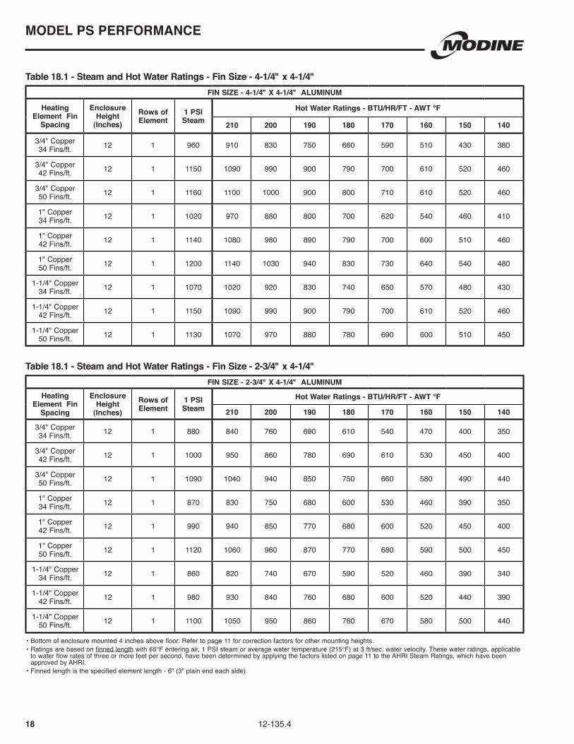
Table 18.1 - Steam and Hot Water Ratings - Fin Size - 4-1/4" x 4-1/4"
Table 18.1 - Steam and Hot Water Ratings - Fin Size - 2-3/4" x 4-1/4"
• Bottom of enclosure mounted 4 inches above floor. Refer to page 11 for correction factors for other mounting heights.• Ratings are based on finned length with 65°F entering air, 1 PSI steam or average water temperature (215°F) at 3 ft/sec . water velocity . These water ratings, applicable
to water flow rates of three or more feet per second, have been determined by applying the factors listed on page 11 to the AHRI Steam Ratings, which have been approved by AHRI .
• Finned length is the specified element length - 6" (3" plain end each side).
FIN SIZE - 4-1/4" x 4-1/4" ALUMINUM
Heating Element Fin
Spacing
Enclosure Height
(Inches)Rows of Element
1 PSI Steam
Hot Water Ratings - BTU/HR/FT - AWT °F
210 200 190 180 170 160 150 140
3/4" Copper 34 Fins/ft . 12 1 960 910 830 750 660 590 510 430 380
3/4" Copper 42 Fins/ft . 12 1 1150 1090 990 900 790 700 610 520 460
3/4" Copper 50 Fins/ft . 12 1 1160 1100 1000 900 800 710 610 520 460
1" Copper 34 Fins/ft . 12 1 1020 970 880 800 700 620 540 460 410
1" Copper 42 Fins/ft . 12 1 1140 1080 980 890 790 700 600 510 460
1" Copper 50 Fins/ft . 12 1 1200 1140 1030 940 830 730 640 540 480
1-1/4" Copper 34 Fins/ft . 12 1 1070 1020 920 830 740 650 570 480 430
1-1/4" Copper 42 Fins/ft . 12 1 1150 1090 990 900 790 700 610 520 460
1-1/4" Copper 50 Fins/ft . 12 1 1130 1070 970 880 780 690 600 510 450
FIN SIZE - 2-3/4" x 4-1/4" ALUMINUMHeating
Element Fin Spacing
Enclosure Height
(Inches)Rows of Element
1 PSI Steam
Hot Water Ratings - BTU/HR/FT - AWT °F
210 200 190 180 170 160 150 140
3/4" Copper 34 Fins/ft . 12 1 880 840 760 690 610 540 470 400 350
3/4" Copper 42 Fins/ft . 12 1 1000 950 860 780 690 610 530 450 400
3/4" Copper 50 Fins/ft . 12 1 1090 1040 940 850 750 660 580 490 440
1" Copper 34 Fins/ft . 12 1 870 830 750 680 600 530 460 390 350
1" Copper 42 Fins/ft . 12 1 990 940 850 770 680 600 520 450 400
1" Copper 50 Fins/ft . 12 1 1120 1060 960 870 770 680 590 500 450
1-1/4" Copper 34 Fins/ft . 12 1 860 820 740 670 590 520 460 390 340
1-1/4" Copper 42 Fins/ft . 12 1 980 930 840 760 680 600 520 440 390
1-1/4" Copper 50 Fins/ft . 12 1 1100 1050 950 860 760 670 580 500 440

1912-135.4
• Enclosure ➁ engages concealed Hanger Strip ➂ .• Enclosure Wall Support (EWS) ➃ hangs from Hanger Strip at
any location and attaches to wall with one fastener .• EWS ➃ supports Heating Element ➀, second and third
row Element Support Assembly (ESA) ➄ and Return Pipe Hanger ➅ without fasteners .
• EWS ➃ supports have integral enclosure lock .
5-1/4"
24"
6"
6"
5-1/4"
18"
2-5/8" 2-5/8"
6"
5-1/4"
12"
2-5/8"
2-7/8" 2-7/8" 2-7/8"
➀ Heating Element➁ Enclosure➂ Hanger Strip➃ Enclosure Wall Support (EWS)➄ Element Support Assembly (ESA)➅ Return Pipe Hanger
Standard Features• Hanger strip - 20 gauge aluminized steel .• Enclosure, 18 gauge in lengths of 2 feet through 8 feet in 6
inch increments .• Heights of 12, 18 and 24 inches .• Enclosure sections are joined using concealed slip joints .• Baked on polyester powdercoat paint finish, tan color .
Accessories• Accessories, 20 gauge, include all items for a complete
installation .• End caps, end enclosures and valve compartments use slip
joints to attach to enclosure .• Inside, outside corners and enclosure extensions overlap
enclosure sections .• Return pipe hanger . Note: return pipe hanger cannot be used
with damper option .
Options• Enclosures available in 14 or 16 gauge steel .• Baked on polyester powdercoat paint finish available in
colors selected from color guide (75-403) .• Bottom inlet grille conceals open air inlet for installations
above eye level .• Hanger strip with full back panel .• Knob operated or tamperproof (key) damper .• Column enclosure conceals piping around columns .
T 012 T 018 T 024
MODEL T TOP OUTLET FEATURES
Figure 19.1 - System Components

20 12-135.4
FIN SIZE - 4-1/4" x 4-1/4" ALUMINUM Heating Enclosure Rows of 1 PSI Hot Water Ratings - BTU/HR/FT - AWT °F Element Height Element Steam Fin Spacing (Inches) 210 200 190 180 170 160 150 140 12 1 1240 1180 1070 970 860 760 660 560 500 18 1 1480 1410 1270 1150 1020 900 780 670 590 3/4" Copper 24 1 1520 1440 1310 1190 1050 930 810 680 610 18 2 @ 6" 1900 1810 1630 1480 1310 1160 1010 860 760 34 Fins/ft . 24 2 @ 6" 1950 1850 1680 1520 1350 1190 1030 880 780 24 2 @ 12" 2020 1920 1740 1580 1390 1230 1070 910 810 24 3 @ 6" 2280 2170 1960 1780 1570 1390 1210 1030 910 12 1 1370 1300 1180 1070 950 840 730 620 550 18 1 1620 1540 1390 1260 1120 990 860 730 650 3/4" Copper 24 1 1660 1580 1430 1290 1150 1010 880 750 660 18 2 @ 6" 2090 1990 1800 1630 1440 1270 1110 940 840 42 Fins/ft . 24 2 @ 6" 2140 2030 1840 1670 1480 1310 1130 960 860 24 2 @ 12" 2220 2110 1910 1730 1530 1350 1180 1000 890 24 3 @ 6" 2520 2390 2170 1970 1740 1540 1340 1130 1010 12 1 1490 1420 1280 1160 1030 910 790 670 600 18 1 1760 1670 1510 1370 1210 1070 930 790 700 3/4" Copper 24 1 1810 1720 1560 1410 1250 1100 960 810 720 18 2 @ 6" 2280 2170 1960 1780 1570 1390 1210 1030 910 50 Fins/ft . 24 2 @ 6" 2340 2220 2010 1830 1610 1430 1240 1050 940 24 2 @ 12" 2430 2310 2090 1900 1680 1480 1290 1090 970 24 3 @ 6" 2740 2600 2360 2140 1890 1670 1450 1230 1100 12 1 1310 1240 1130 1020 900 800 690 590 520 18 1 1610 1530 1380 1260 1110 980 850 720 640 1" Copper 24 1 1770 1680 1520 1380 1220 1080 940 800 710 18 2 @ 6" 2080 1980 1790 1620 1440 1270 1100 940 830 34 Fins/ft . 24 2 @ 6" 2280 2170 1960 1780 1570 1390 1210 1030 910 24 2 @ 12" 2370 2250 2040 1850 1640 1450 1260 1070 950 24 3 @ 6" 2650 2520 2280 2070 1830 1620 1400 1190 1060 12 1 1430 1360 1230 1120 990 870 760 640 570 18 1 1760 1670 1510 1370 1210 1070 930 790 700 1" Copper 24 1 1940 1840 1670 1510 1340 1180 1030 870 780 18 2 @ 6" 2280 2170 1960 1780 1570 1390 1210 1030 910 42 Fins/ft . 24 2 @ 6" 2500 2380 2150 1950 1730 1530 1330 1130 1000 24 2 @ 12" 2590 2460 2230 2020 1790 1580 1370 1170 1040 24 3 @ 6" 2930 2780 2520 2290 2020 1790 1550 1320 1170 12 1 1540 1460 1320 1200 1060 940 820 690 620 18 1 1890 1800 1630 1470 1300 1150 1000 850 760 1" Copper 24 1 2080 1980 1790 1620 1440 1270 1100 940 830 18 2 @ 6" 2450 2330 2110 1910 1690 1490 1300 1100 980 50 Fins/ft . 24 2 @ 6" 2690 2560 2310 2100 1860 1640 1430 1210 1080 24 2 @ 12" 2780 2640 2390 2170 1920 1700 1470 1250 1110 24 3 @ 6" 3150 2990 2710 2460 2170 1920 1670 1420 1260 12 1 1380 1310 1190 1080 950 840 730 620 550 18 1 1700 1620 1460 1330 1170 1040 900 770 680 1-1/4" Copper 24 1 1860 1770 1600 1450 1280 1130 990 840 740 18 2 @ 6" 2190 2080 1880 1710 1510 1340 1160 990 880 34 Fins/ft . 24 2 @ 6" 2410 2290 2070 1880 1660 1470 1280 1080 960 24 2 @ 12" 2490 2370 2140 1940 1720 1520 1320 1120 1000 24 3 @ 6" 2810 2670 2420 2190 1940 1710 1490 1260 1120 12 1 1500 1430 1290 1170 1040 920 800 680 600 18 1 1850 1760 1590 1440 1280 1130 980 830 740 1-1/4" Copper 24 1 2030 1930 1750 1580 1400 1240 1080 910 810 18 2 @ 6" 2390 2270 2060 1860 1650 1460 1270 1080 960 42 Fins/ft . 24 2 @ 6" 2630 2500 2260 2050 1810 1600 1390 1180 1050 24 2 @ 12" 2720 2580 2340 2120 1880 1660 1440 1220 1090 24 3 @ 6" 3070 2920 2640 2390 2120 1870 1630 1380 1230 12 1 1590 1510 1370 1240 1100 970 840 720 640 18 1 1960 1860 1690 1530 1350 1200 1040 880 780 1-1/4" Copper 24 1 2150 2040 1850 1680 1480 1310 1140 970 860 18 2 @ 6" 2530 2400 2180 1970 1750 1540 1340 1140 1010 50 Fins/ft . 24 2 @ 6" 2780 2640 2390 2170 1920 1700 1470 1250 1110 24 2 @ 12" 2880 2740 2480 2250 1990 1760 1530 1300 1150 24 3 @ 6" 3250 3090 2800 2540 2240 1980 1720 1460 1300
Table 20.1 - Steam and Hot Water Ratings - Fin Size - 4-1/4" x 4-1/4"
MODEL T PERFORMANCE
• Bottom of enclosure mounted 4 inches above floor. Refer to page 11 for correction factors for other mounting heights.• Ratings are based on finned length with 65°F entering air, 1 PSI steam or average water temperature (215°F) at
3 ft/sec . water velocity . These water ratings, applicable to water flow rates of three or more feet per second, have been determined by applying the factors listed on page 11 to the AHRI Steam Ratings, which have been approved by AHRI .
• Finned length is the specified element length - 6" (3" plain end each side).
Bold, italicized units are

2112-135.4
Table 21.1 - Steam and Hot Water Ratings - Fin Size - 2-3/4" x 4-1/4"FIN SIZE - 2-3/4" x 4-1/4" ALUMINUM
Heating Enclosure Rows of 1 PSI Hot Water Ratings - BTU/HR/FT - AWT °F Element Height Element Steam Fin Spacing (Inches) 210 200 190 180 170 160 150 140
12 1 1130 1070 970 880 780 690 600 510 450 18 1 1340 1270 1150 1050 920 820 710 600 540 3/4" Copper 24 1 1380 1310 1190 1080 950 840 730 620 550 18 2 @ 6" 1680 1600 1440 1310 1160 1020 890 760 670 34 Fins/ft . 24 2 @ 6" 1720 1630 1480 1340 1190 1050 910 770 690 24 2 @ 12" 1790 1700 1540 1400 1240 1090 950 810 720 24 3 @ 6" 1950 1850 1680 1520 1350 1190 1030 880 780 12 1 1310 1240 1130 1020 900 800 690 590 520 18 1 1500 1430 1290 1170 1040 920 800 680 600 3/4" Copper 24 1 1570 1490 1350 1220 1080 960 830 710 630 18 2 @ 6" 1910 1810 1640 1490 1320 1170 1010 860 760 42 Fins/ft . 24 2 @ 6" 1960 1860 1690 1530 1350 1200 1040 880 780 24 2 @ 12" 2030 1930 1750 1580 1400 1240 1080 910 810 24 3 @ 6" 2220 2110 1910 1730 1530 1350 1180 1000 890 12 1 1450 1380 1250 1130 1000 880 770 650 580 18 1 1720 1630 1480 1340 1190 1050 910 770 690 3/4" Copper 24 1 1770 1680 1520 1380 1220 1080 940 800 710 18 2 @ 6" 2150 2040 1850 1680 1480 1310 1140 970 860 50 Fins/ft . 24 2 @ 6" 2210 2100 1900 1720 1520 1350 1170 990 880 24 2 @ 12" 2290 2180 1970 1790 1580 1400 1210 1030 920 24 3 @ 6" 2490 2370 2140 1940 1720 1520 1320 1120 1000 12 1 1110 1050 950 870 770 680 590 500 440 18 1 1370 1300 1180 1070 950 840 730 620 550 1" Copper 24 1 1500 1430 1290 1170 1040 920 800 680 600 18 2 @ 6" 1710 1620 1470 1330 1180 1040 910 770 680 34 Fins/ft . 24 2 @ 6" 1880 1790 1620 1470 1300 1150 1000 850 750 24 2 @ 12" 1950 1850 1680 1520 1350 1190 1030 880 780 24 3 @ 6" 2110 2000 1810 1650 1460 1290 1120 950 840 12 1 1240 1180 1070 970 860 760 660 560 500 18 1 1530 1450 1320 1190 1060 930 810 690 610 1" Copper 24 1 1670 1590 1440 1300 1150 1020 890 750 670 18 2 @ 6" 1910 1810 1640 1490 1320 1170 1010 860 760 42 Fins/ft . 24 2 @ 6" 2090 1990 1800 1630 1440 1270 1110 940 840 24 2 @ 12" 2170 2060 1870 1690 1500 1320 1150 980 870 24 3 @ 6" 2360 2240 2030 1840 1630 1440 1250 1060 940 12 1 1370 1300 1180 1070 950 840 730 620 550 18 1 1690 1610 1450 1320 1170 1030 900 760 680 1" Copper 24 1 1850 1760 1590 1440 1280 1130 980 830 740 18 2 @ 6" 2110 2000 1810 1650 1460 1290 1120 950 840 50 Fins/ft . 24 2 @ 6" 2310 2190 1990 1800 1590 1410 1220 1040 920 24 2 @ 12" 2400 2280 2060 1870 1660 1460 1270 1080 960 24 3 @ 6" 2620 2490 2250 2040 1810 1600 1390 1180 1050 12 1 1060 1010 910 830 730 650 560 480 420 18 1 1300 1240 1120 1010 900 790 690 590 520 1-1/4" Copper 24 1 1430 1360 1230 1120 990 870 760 640 570 18 2 @ 6" 1640 1560 1410 1280 1130 1000 870 740 660 34 Fins/ft . 24 2 @ 6" 1800 1710 1550 1400 1240 1100 950 810 720 24 2 @ 12" 1870 1780 1610 1460 1290 1140 990 840 750 24 3 @ 6" 2040 1940 1750 1590 1410 1240 1080 920 820 12 1 1180 1120 1010 920 810 720 630 530 470 18 1 1450 1380 1250 1130 1000 880 770 650 580 1-1/4" Copper 24 1 1590 1510 1370 1240 1100 970 840 720 640 18 2 @ 6" 1810 1720 1560 1410 1250 1100 960 810 720 42 Fins/ft . 24 2 @ 6" 1990 1890 1710 1550 1370 1210 1050 900 800 24 2 @ 12" 2060 1960 1770 1610 1420 1260 1090 930 820 24 3 @ 6" 2240 2130 1930 1750 1550 1370 1190 1010 900 12 1 1290 1230 1110 1010 890 790 680 580 520 18 1 1590 1510 1370 1240 1100 970 840 720 640 1-1/4" Copper 24 1 1740 1650 1500 1360 1200 1060 920 780 700 18 2 @ 6" 1990 1890 1710 1550 1370 1210 1050 900 800 50 Fins/ft . 24 2 @ 6" 2180 2070 1870 1700 1500 1330 1160 980 870 24 2 @ 12" 2260 2150 1940 1760 1560 1380 1200 1020 900 24 3 @ 6" 2460 2340 2120 1920 1700 1500 1300 1110 980
MODEL T PERFORMANCE
• Bottom of enclosure mounted 4 inches above floor. Refer to page 11 for correction factors for other mounting heights.• Ratings are based on finned length with 65°F entering air, 1 PSI steam or average water temperature (215°F) at 3 ft/sec . water velocity . These water ratings, applicable
to water flow rates of three or more feet per second, have been determined by applying the factors listed on page 11 to the AHRI Steam Ratings, which have been approved by AHRI .
• Finned length is the specified element length - 6" (3" plain end each side).
22 12-135.4
• Enclosure ➁ engages concealed Hanger Strip ➂ .• Enclosure Wall Support (EWS) ➃ hangs from Hanger Strip at
any location and attaches to wall with one fastener .• EWS ➃ supports Heating Element ➀, second and third row
Element Support Assembly (ESA) ➄ and Return Pipe Hanger ➅ without fasteners .
• EWS ➃ supports have integral enclosure lock .
5-1/4"
24"
2-5/8"
6"
2-7/8"
5-1/4"
18"
2-5/8"
6"
2 7/8"
5-1/4"
12"
2-5/8"
2-7/8"
6"
F 012 F 018 F 024
MODEL F FRONT OUTLET FEATURES
➀ Heating Element➁ Enclosure➂ Hanger Strip➃ Enclosure Wall Support (EWS)➄ Element Support Assembly (ESA)➅ Return Pipe Hanger
Standard Features• Hanger strip - 20 gauge aluminized steel .• Enclosure, 18 gauge in lengths of 2 feet through 8 feet in
6 inch increments .• Heights of 12, 18 and 24 inches .• Enclosure sections are joined using concealed slip joints .• Baked on polyester powdercoat paint finish, tan color .
Accessories• Accessories, 20 gauge, include all items for a complete
installation .• End caps, end enclosures and valve compartments use slip
joints to attach to enclosure .• Inside, outside corners and enclosure extensions overlap
enclosure sections .• Return pipe hanger . Note: return pipe hanger cannot be used
with damper option .
Options• Enclosures available in 14 or 16 gauge steel .• Baked on polyester powdercoat paint finish available in
colors selected from color guide (75-403) .• Bottom inlet grille conceals open air inlet for installations
above eye level .• Hanger strip with full back panel .• Knob operated or tamperproof (key) damper .• Column enclosure conceals piping around columns .
Figure 22.1 - System Components

2312-135.4
Table 23.1 - Steam and Hot Water Ratings - Fin Size - 4-1/4" x 4-1/4"FIN SIZE - 4-1/4" x 4-1/4" ALUMINUM
Heating Enclosure Rows of 1 PSI Hot Water Ratings - BTU/HR/FT - AWT °F Element Height Element Steam Fin Spacing (Inches) 210 200 190 180 170 160 150 140
12 1 1350 1280 1160 1050 930 820 720 610 540 18 1 1620 1540 1390 1260 1120 990 860 730 650 3/4" Copper 24 1 1680 1600 1440 1310 1160 1020 890 760 670 18 2 @ 6" 2080 1980 1790 1620 1440 1270 1100 940 830 34 Fins/ft . 24 2 @ 6" 2160 2050 1860 1680 1490 1320 1140 970 860 24 2 @ 12" 2240 2130 1930 1750 1550 1370 1190 1010 900 24 3 @ 6" 2520 2390 2170 1970 1740 1540 1340 1130 1010 12 1 1480 1410 1270 1150 1020 900 780 670 590 18 1 1780 1690 1530 1390 1230 1090 940 800 710 3/4" Copper 24 1 1840 1750 1580 1440 1270 1120 980 830 740 18 2 @ 6" 2290 2180 1970 1790 1580 1400 1210 1030 920 42 Fins/ft . 24 2 @ 6" 2380 2260 2050 1860 1640 1450 1260 1070 950 24 2 @ 12" 2460 2340 2120 1920 1700 1500 1300 1110 980 24 3 @ 6" 2800 2660 2410 2180 1930 1710 1480 1260 1120 12 1 1610 1530 1380 1260 1110 980 850 720 640 18 1 1930 1830 1660 1510 1330 1180 1020 870 770 3/4" Copper 24 1 2010 1910 1730 1570 1390 1230 1070 900 800 18 2 @ 6" 2500 2380 2150 1950 1730 1530 1330 1130 1000 50 Fins/ft . 24 2 @ 6" 2590 2460 2230 2020 1790 1580 1370 1170 1040 24 2 @ 12" 2690 2560 2310 2100 1860 1640 1430 1210 1080 24 3 @ 6" 3040 2890 2610 2370 2100 1850 1610 1370 1220 12 1 1420 1350 1220 1110 980 870 750 640 570 18 1 1700 1620 1460 1330 1170 1040 900 770 680 1" Copper 24 1 1770 1680 1520 1380 1220 1080 940 800 710 18 2 @ 6" 2200 2090 1890 1720 1520 1340 1170 990 880 34 Fins/ft . 24 2 @ 6" 2280 2170 1960 1780 1570 1390 1210 1030 910 24 2 @ 12" 2360 2240 2030 1840 1630 1440 1250 1060 940 24 3 @ 6" 2650 2520 2280 2070 1830 1620 1400 1190 1060 12 1 1550 1470 1330 1210 1070 950 820 700 620 18 1 1860 1770 1600 1450 1280 1130 990 840 740 1" Copper 24 1 1940 1840 1670 1510 1340 1180 1030 870 780 18 2 @ 6" 2410 2290 2070 1880 1660 1470 1280 1080 960 42 Fins/ft . 24 2 @ 6" 2500 2380 2150 1950 1730 1530 1330 1130 1000 24 2 @ 12" 2590 2460 2230 2020 1790 1580 1370 1170 1040 24 3 @ 6" 2930 2780 2520 2290 2020 1790 1550 1320 1170 12 1 1670 1590 1440 1300 1150 1020 890 750 670 18 1 2000 1900 1720 1560 1380 1220 1060 900 800 1" Copper 24 1 2080 1980 1790 1620 1440 1270 1100 940 830 18 2 @ 6" 2580 2450 2220 2010 1780 1570 1370 1160 1030 50 Fins/ft . 24 2 @ 6" 2680 2550 2300 2090 1850 1630 1420 1210 1070 24 2 @ 12" 2780 2640 2390 2170 1920 1700 1470 1250 1110 24 3 @ 6" 3150 2990 2710 2460 2170 1920 1670 1420 1260 12 1 1490 1420 1280 1160 1030 910 790 670 600 18 1 1790 1700 1540 1400 1240 1090 950 810 720 1-1/4" Copper 24 1 1860 1770 1600 1450 1280 1130 990 840 740 18 2 @ 6" 2320 2200 2000 1810 1600 1420 1230 1040 930 34 Fins/ft . 24 2 @ 6" 2410 2290 2070 1880 1660 1470 1280 1080 960 24 2 @ 12" 2490 2370 2140 1940 1720 1520 1320 1120 1000 24 3 @ 6" 2810 2670 2420 2190 1940 1710 1490 1260 1120 12 1 1630 1550 1400 1270 1120 990 860 730 650 18 1 1950 1850 1680 1520 1350 1190 1030 880 780 1-1/4" Copper 24 1 2030 1930 1750 1580 1400 1240 1080 910 810 18 2 @ 6" 2530 2400 2180 1970 1750 1540 1340 1140 1010 42 Fins/ft . 24 2 @ 6" 2620 2490 2250 2040 1810 1600 1390 1180 1050 24 2 @ 12" 2720 2580 2340 2120 1880 1660 1440 1220 1090 24 3 @ 6" 3070 2920 2640 2390 2120 1870 1630 1380 1230 12 1 1720 1630 1480 1340 1190 1050 910 770 690 18 1 2070 1970 1780 1610 1430 1260 1100 930 830 1-1/4" Copper 24 1 2150 2040 1850 1680 1480 1310 1140 970 860 18 2 @ 6" 2670 2540 2300 2080 1840 1630 1420 1200 1070 50 Fins/ft . 24 2 @ 6" 2780 2640 2390 2170 1920 1700 1470 1250 1110 24 2 @ 12" 2880 2740 2480 2250 1990 1760 1530 1300 1150 24 3 @ 6" 3240 3080 2790 2530 2240 1980 1720 1460 1300
MODEL F PERFORMANCE
• Bottom of enclosure mounted 4 inches above floor. Refer to page 11 for correction factors for other mounting heights.• Ratings are based on finned length with 65°F entering air, 1 PSI steam or average water temperature (215°F) at
3 ft/sec . water velocity . These water ratings, applicable to water flow rates of three or more feet per second, have been determined by applying the factors listed on page 11 to the AHRI Steam Ratings, which have been approved by AHRI .
• Finned length is the specified element length - 6" (3" plain end each side).
Bold, italicized units are

24 12-135.4
Table 24.1 - Steam and Hot Water Ratings - Fin Size - 2-3/4" x 4-1/4"FIN SIZE - 2-3/4" x 4-1/4" ALUMINUM
Heating Enclosure Rows of 1 PSI Hot Water Ratings - BTU/HR/FT - AWT °F Element Height Element Steam Fin Spacing (Inches) 210 200 190 180 170 160 150 140 12 1 1230 1170 1060 960 850 750 650 550 490 18 1 1470 1400 1260 1150 1010 900 780 660 590 3/4" Copper 24 1 1530 1450 1320 1190 1060 930 810 690 610 18 2 @ 6" 1840 1750 1580 1440 1270 1120 980 830 740 34 Fins/ft . 24 2 @ 6" 1910 1810 1640 1490 1320 1170 1010 860 760 24 2 @ 12" 1980 1880 1700 1540 1370 1210 1050 890 790 24 3 @ 6" 2160 2050 1860 1680 1490 1320 1140 970 860 12 1 1400 1330 1200 1090 970 850 740 630 560 18 1 1670 1590 1440 1300 1150 1020 890 750 670 3/4" Copper 24 1 1740 1650 1500 1360 1200 1060 920 780 700 18 2 @ 6" 2090 1990 1800 1630 1440 1270 1110 940 840 42 Fins/ft . 24 2 @ 6" 2170 2060 1870 1690 1500 1320 1150 980 870 24 2 @ 12" 2250 2140 1940 1760 1550 1370 1190 1010 900 24 3 @ 6" 2460 2340 2120 1920 1700 1500 1300 1110 980 12 1 1570 1490 1350 1220 1080 960 830 710 630 18 1 1880 1790 1620 1470 1300 1150 1000 850 750 3/4" Copper 24 1 1960 1860 1690 1530 1350 1200 1040 880 780 18 2 @ 6" 2360 2240 2030 1840 1630 1440 1250 1060 940 50 Fins/ft . 24 2 @ 6" 2450 2330 2110 1910 1690 1490 1300 1100 980 24 2 @ 12" 2540 2410 2180 1980 1750 1550 1350 1140 1020 24 3 @ 6" 2760 2620 2370 2150 1900 1680 1460 1240 1100 12 1 1200 1140 1030 940 830 730 640 540 480 18 1 1440 1370 1240 1120 990 880 760 650 580 1" Copper 24 1 1500 1430 1290 1170 1040 920 800 680 600 18 2 @ 6" 1810 1720 1560 1410 1250 1100 960 810 720 34 Fins/ft . 24 2 @ 6" 1880 1790 1620 1470 1300 1150 1000 850 750 24 2 @ 12" 1950 1850 1680 1520 1350 1190 1030 880 780 24 3 @ 6" 2110 2000 1810 1650 1460 1290 1120 950 840 12 1 1340 1270 1150 1050 920 820 710 600 540 18 1 1610 1530 1380 1260 1110 980 850 720 640 1" Copper 24 1 1670 1590 1440 1300 1150 1020 890 750 670 18 2 @ 6" 2010 1910 1730 1570 1390 1230 1070 900 800 42 Fins/ft . 24 2 @ 6" 2090 1990 1800 1630 1440 1270 1110 940 840 24 2 @ 12" 2170 2060 1870 1690 1500 1320 1150 980 870 24 3 @ 6" 2360 2240 2030 1840 1630 1440 1250 1060 940 12 1 1490 1420 1280 1160 1030 910 790 670 600 18 1 1780 1690 1530 1390 1230 1090 940 800 710 1" Copper 24 1 1850 1760 1590 1440 1280 1130 980 830 740 18 2 @ 6" 2230 2120 1920 1740 1540 1360 1180 1000 890 50 Fins/ft . 24 2 @ 6" 2310 2190 1990 1800 1590 1410 1220 1040 920 24 2 @ 12" 2400 2280 2060 1870 1660 1460 1270 1080 960 24 3 @ 6" 2620 2490 2250 2040 1810 1600 1390 1180 1050 12 1 1150 1090 990 900 790 700 610 520 460 18 1 1380 1310 1190 1080 950 840 730 620 550 1-1/4" Copper 24 1 1430 1360 1230 1120 990 870 760 640 570 18 2 @ 6" 1730 1640 1490 1350 1190 1060 920 780 690 34 Fins/ft . 24 2 @ 6" 1800 1710 1550 1400 1240 1100 950 810 720 24 2 @ 12" 1860 1770 1600 1450 1280 1130 990 840 740 24 3 @ 6" 2040 1940 1750 1590 1410 1240 1080 920 820 12 1 1280 1220 1100 1000 880 780 680 580 510 18 1 1530 1450 1320 1190 1060 930 810 690 610 1-1/4" Copper 24 1 1590 1510 1370 1240 1100 970 840 720 640 18 2 @ 6" 1910 1810 1640 1490 1320 1170 1010 860 760 42 Fins/ft . 24 2 @ 6" 1990 1890 1710 1550 1370 1210 1050 900 800 24 2 @ 12" 2060 1960 1770 1610 1420 1260 1090 930 820 24 3 @ 6" 2230 2120 1920 1740 1540 1360 1180 1000 890 12 1 1400 1330 1200 1090 970 850 740 630 560 18 1 1680 1600 1440 1310 1160 1020 890 760 670 1-1/4" Copper 24 1 1740 1650 1500 1360 1200 1060 920 780 700 18 2 @ 6" 2100 2000 1810 1640 1450 1280 1110 950 840 50 Fins/ft . 24 2 @ 6" 2180 2070 1870 1700 1500 1330 1160 980 870 24 2 @ 12" 2260 2150 1940 1760 1560 1380 1200 1020 900 24 3 @ 6" 2460 2340 2120 1920 1700 1500 1300 1110 980
MODEL F PERFORMANCE
• Bottom of enclosure mounted 4 inches above floor. Refer to page 11 for correction factors for other mounting heights.• Ratings are based on finned length with 65°F entering air, 1 PSI steam or average water temperature (215°F) at 3 ft/sec . water velocity . These water ratings, applicable
to water flow rates of three or more feet per second, have been determined by applying the factors listed on page 11 to the AHRI Steam Ratings, which have been approved by AHRI .
• Finned length is the specified element length - 6" (3" plain end each side).

2512-135.4
• Enclosure (2) engages concealed Hanger Strip ➂ .• Enclosure Wall Support (EWS) ➃ hangs from Hanger Strip at
any location and attaches to wall with one fastener .• EWS (4) supports Heating Element ➀, second and third row
Element Support Assembly (ESA) ➄ and Return Pipe Hanger ➅ without fasteners .
• EWS ➃ supports have integral enclosure lock .
5-1/4"
24"
2-5/8"
6"
6"
2-7/8"
5-1/4"
18"
2-5/8"
6"
2-7/8"
5-1/4"
12"
2-5/8"
2-7/8"
Standard Features• Hanger strip - 20 gauge aluminized steel .• Enclosure, 18 gauge in lengths of 2 feet through 8 feet in 6
inch increments .• Heights of 12, 18 and 24 inches .• Enclosure sections are joined using concealed slip joints .• Baked on polyester powdercoat paint finish, tan color .
Accessories• Accessories, 20 gauge, include all items for a complete
installation .• End caps, end enclosures and valve compartments use slip
joints to attach to enclosure .• Inside, outside corners and enclosure extensions overlap
enclosure sections .• Return pipe hanger . Note: return pipe hanger cannot be used
with damper option .
Options• Enclosures available in 14 or 16 gauge steel .• Baked on polyester powdercoat paint finish available in
colors selected from color guide (75-403) .• Bottom inlet grille conceals open air inlet for installations
above eye level .• Hanger strip with full back panel .• Knob operated or tamperproof (key) damper .• Column enclosure conceals piping around columns .
R 012 R 018 R 024
MODEL R FRONT AND TOP OUTLET FEATURES
➀ Heating Element➁ Enclosure➂ Hanger Strip➃ Enclosure Wall Support (EWS)➄ Element Support Assembly (ESA)➅ Return Pipe Hanger
Figure 25.1 - System Components

26 12-135.4
FIN SIZE - 4-1/4" x 4-1/4" ALUMINUM Heating Enclosure Rows of 1 PSI Hot Water Ratings - BTU/HR/FT - AWT °F Element Height Element Steam Fin Spacing (Inches) 210 200 190 180 170 160 150 140 12 1 1400 1330 1200 1090 970 850 740 630 560 18 1 1710 1620 1470 1330 1180 1040 910 770 680 3/4" Copper 24 1 1830 1740 1570 1430 1260 1120 970 820 730 18 2 @ 6" 2200 2090 1890 1720 1520 1340 1170 990 880 34 Fins/ft . 24 2 @ 6" 2350 2230 2020 1830 1620 1430 1250 1060 940 24 2 @ 12" 2430 2310 2090 1900 1680 1480 1290 1090 970 24 3 @ 6" 2740 2600 2360 2140 1890 1670 1450 1230 1100 12 1 1540 1460 1320 1200 1060 940 820 690 620 18 1 1880 1790 1620 1470 1300 1150 1000 850 750 3/4" Copper 24 1 2000 1900 1720 1560 1380 1220 1060 900 800 18 2 @ 6" 2420 2300 2080 1890 1670 1480 1280 1090 970 42 Fins/ft . 24 2 @ 6" 2580 2450 2220 2010 1780 1570 1370 1160 1030 24 2 @ 12" 2680 2550 2300 2090 1850 1630 1420 1210 1070 24 3 @ 6" 3040 2890 2610 2370 2100 1850 1610 1370 1220 12 1 1670 1590 1440 1300 1150 1020 890 750 670 18 1 2040 1940 1750 1590 1410 1240 1080 920 820 3/4" Copper 24 1 2180 2070 1870 1700 1500 1330 1160 980 870 18 2 @ 6" 2640 2510 2270 2060 1820 1610 1400 1190 1060 50 Fins/ft . 24 2 @ 6" 2820 2680 2430 2200 1950 1720 1490 1270 1130 24 2 @ 12" 2920 2770 2510 2280 2010 1780 1550 1310 1170 24 3 @ 6" 3300 3140 2840 2570 2280 2010 1750 1490 1320 12 1 1470 1400 1260 1150 1010 900 780 660 590 18 1 1800 1710 1550 1400 1240 1100 950 810 720 1" Copper 24 1 1920 1820 1650 1500 1320 1170 1020 860 770 18 2 @ 6" 2320 2200 2000 1810 1600 1420 1230 1040 930 34 Fins/ft . 24 2 @ 6" 2480 2360 2130 1930 1710 1510 1310 1120 990 24 2 @ 12" 2570 2440 2210 2000 1770 1570 1360 1160 1030 24 3 @ 6" 2880 2740 2480 2250 1990 1760 1530 1300 1150 12 1 1610 1530 1380 1260 1110 980 850 720 640 18 1 1970 1870 1690 1540 1360 1200 1040 890 790 1" Copper 24 1 2100 2000 1810 1640 1450 1280 1110 950 840 18 2 @ 6" 2540 2410 2180 1980 1750 1550 1350 1140 1020 42 Fins/ft . 24 2 @ 6" 2710 2570 2330 2110 1870 1650 1440 1220 1080 24 2 @ 12" 2810 2670 2420 2190 1940 1710 1490 1260 1120 24 3 @ 6" 3180 3020 2730 2480 2190 1940 1690 1430 1270 12 1 1730 1640 1490 1350 1190 1060 920 780 690 18 1 2110 2000 1810 1650 1460 1290 1120 950 840 1" Copper 24 1 2250 2140 1940 1760 1550 1370 1190 1010 900 18 2 @ 6" 2730 2590 2350 2130 1880 1670 1450 1230 1090 50 Fins/ft . 24 2 @ 6" 2910 2760 2500 2270 2010 1780 1540 1310 1160 24 2 @ 12" 3020 2870 2600 2360 2080 1840 1600 1360 1210 24 3 @ 6" 3420 3250 2940 2670 2360 2090 1810 1540 1370 12 1 1550 1470 1330 1210 1070 950 820 700 620 18 1 1890 1800 1630 1470 1300 1150 1000 850 760 1-1/4" Copper 24 1 2020 1920 1740 1580 1390 1230 1070 910 810 18 2 @ 6" 2450 2330 2110 1910 1690 1490 1300 1100 980 34 Fins/ft . 24 2 @ 6" 2610 2480 2240 2040 1800 1590 1380 1170 1040 24 2 @ 12" 2710 2570 2330 2110 1870 1650 1440 1220 1080 24 3 @ 6" 3050 2900 2620 2380 2100 1860 1620 1370 1220 12 1 1690 1610 1450 1320 1170 1030 900 760 680 18 1 2070 1970 1780 1610 1430 1260 1100 930 830 1-1/4" Copper 24 1 2200 2090 1890 1720 1520 1340 1170 990 880 18 2 @ 6" 2670 2540 2300 2080 1840 1630 1420 1200 1070 42 Fins/ft . 24 2 @ 6" 2850 2710 2450 2220 1970 1740 1510 1280 1140 24 2 @ 12" 2950 2800 2540 2300 2040 1800 1560 1330 1180 24 3 @ 6" 3330 3160 2860 2600 2300 2030 1760 1500 1330 12 1 1790 1700 1540 1400 1240 1090 950 810 720 18 1 2190 2080 1880 1710 1510 1340 1160 990 880 1-1/4" Copper 24 1 2330 2210 2000 1820 1610 1420 1230 1050 930 18 2 @ 6" 2830 2690 2430 2210 1950 1730 1500 1270 1130 50 Fins/ft . 24 2 @ 6" 3010 2860 2590 2350 2080 1840 1600 1350 1200 24 2 @ 12" 3120 2960 2680 2430 2150 1900 1650 1400 1250 24 3 @ 6" 3520 3340 3030 2750 2430 2150 1870 1580 1410
Table 26.1 - Steam and Hot Water Ratings - Fin Size - 4-1/4" x 4-1/4"
MODEL R PERFORMANCE
• Bottom of enclosure mounted 4 inches above floor. Refer to page 11 for correction factors for other mounting heights.• Ratings are based on finned length with 65°F entering air, 1 PSI steam or average water temperature (215°F) at
3 ft/sec . water velocity . These water ratings, applicable to water flow rates of three or more feet per second, have been determined by applying the factors listed on page 11 to the AHRI Steam Ratings, which have been approved by AHRI .
• Finned length is the specified element length - 6" (3" plain end each side).
Bold, italicized units are

2712-135.4
Table 27.1 - Steam and Hot Water Ratings - Fin Size - 2-3/4" x 4-1/4"FIN SIZE - 2-3/4" x 4-1/4" ALUMINUM
Heating Enclosure Rows of 1 PSI Hot Water Ratings - BTU/HR/FT - AWT °F Element Height Element Steam Fin Spacing (Inches) 210 200 190 180 170 160 150 140
12 1 1270 1210 1090 990 880 770 670 570 510 18 1 1550 1470 1330 1210 1070 950 820 700 620 3/4" Copper 24 1 1660 1580 1430 1290 1150 1010 880 750 660 18 2 @ 6" 1940 1840 1670 1510 1340 1180 1030 870 780 34 Fins/ft . 24 2 @ 6" 2070 1970 1780 1610 1430 1260 1100 930 830 24 2 @ 12" 2150 2040 1850 1680 1480 1310 1140 970 860 24 3 @ 6" 2340 2220 2010 1830 1610 1430 1240 1050 940 12 1 1450 1380 1250 1130 1000 880 770 650 580 18 1 1770 1680 1520 1380 1220 1080 940 800 710 3/4" Copper 24 1 1890 1800 1630 1470 1300 1150 1000 850 760 18 2 @ 6" 2210 2100 1900 1720 1520 1350 1170 990 880 42 Fins/ft . 24 2 @ 6" 2360 2240 2030 1840 1630 1440 1250 1060 940 24 2 @ 12" 2440 2320 2100 1900 1680 1490 1290 1100 980 24 3 @ 6" 2670 2540 2300 2080 1840 1630 1420 1200 1070 12 1 1630 1550 1400 1270 1120 990 860 730 650 18 1 1990 1890 1710 1550 1370 1210 1050 900 800 3/4" Copper 24 1 2120 2010 1820 1650 1460 1290 1120 950 850 18 2 @ 6" 2490 2370 2140 1940 1720 1520 1320 1120 1000 50 Fins/ft . 24 2 @ 6" 2660 2530 2290 2070 1840 1620 1410 1200 1060 24 2 @ 12" 2760 2620 2370 2150 1900 1680 1460 1240 1100 24 3 @ 6" 3000 2850 2580 2340 2070 1830 1590 1350 1200 12 1 1250 1190 1080 980 860 760 660 560 500 18 1 1520 1440 1310 1190 1050 930 810 680 610 1" Copper 24 1 1630 1550 1400 1270 1120 990 860 730 650 18 2 @ 6" 1910 1810 1640 1490 1320 1170 1010 860 760 34 Fins/ft . 24 2 @ 6" 2040 1940 1750 1590 1410 1240 1080 920 820 24 2 @ 12" 2110 2000 1810 1650 1460 1290 1120 950 840 24 3 @ 6" 2300 2190 1980 1790 1590 1400 1220 1040 920 12 1 1390 1320 1200 1080 960 850 740 630 560 18 1 1700 1620 1460 1330 1170 1040 900 770 680 1" Copper 24 1 1820 1730 1570 1420 1260 1110 960 820 730 18 2 @ 6" 2130 2020 1830 1660 1470 1300 1130 960 850 42 Fins/ft . 24 2 @ 6" 2270 2160 1950 1770 1570 1380 1200 1020 910 24 2 @ 12" 2350 2230 2020 1830 1620 1430 1250 1060 940 24 3 @ 6" 2560 2430 2200 2000 1770 1560 1360 1150 1020 12 1 1540 1460 1320 1200 1060 940 820 690 620 18 1 1880 1790 1620 1470 1300 1150 1000 850 750 1" Copper 24 1 2010 1910 1730 1570 1390 1230 1070 900 800 18 2 @ 6" 2360 2240 2030 1840 1630 1440 1250 1060 940 50 Fins/ft . 24 2 @ 6" 2510 2380 2160 1960 1730 1530 1330 1130 1000 24 2 @ 12" 2600 2470 2240 2030 1790 1590 1380 1170 1040 24 3 @ 6" 2840 2700 2440 2220 1960 1730 1510 1280 1140 12 1 1190 1130 1020 930 820 730 630 540 480 18 1 1460 1390 1260 1140 1010 890 770 660 580 1-1/4" Copper 24 1 1550 1470 1330 1210 1070 950 820 700 620 18 2 @ 6" 1830 1740 1570 1430 1260 1120 970 820 730 34 Fins/ft . 24 2 @ 6" 1950 1850 1680 1520 1350 1190 1030 880 780 24 2 @ 12" 2020 1920 1740 1580 1390 1230 1070 910 810 24 3 @ 6" 2210 2100 1900 1720 1520 1350 1170 990 880 12 1 1320 1250 1140 1030 910 810 700 590 530 18 1 1620 1540 1390 1260 1120 990 860 730 650 1-1/4" Copper 24 1 1720 1630 1480 1340 1190 1050 910 770 690 18 2 @ 6" 2020 1920 1740 1580 1390 1230 1070 910 810 42 Fins/ft . 24 2 @ 6" 2160 2050 1860 1680 1490 1320 1140 970 860 24 2 @ 12" 2230 2120 1920 1740 1540 1360 1180 1000 890 24 3 @ 6" 2430 2310 2090 1900 1680 1480 1290 1090 970 12 1 1550 1470 1330 1210 1070 950 820 700 620 18 1 1780 1690 1530 1390 1230 1090 940 800 710 1-1/4" Copper 24 1 1890 1800 1630 1470 1300 1150 1000 850 760 18 2 @ 6" 2220 2110 1910 1730 1530 1350 1180 1000 890 50 Fins/ft . 24 2 @ 6" 2370 2250 2040 1850 1640 1450 1260 1070 950 24 2 @ 12" 2460 2340 2120 1920 1700 1500 1300 1110 980 24 3 @ 6" 2670 2540 2300 2080 1840 1630 1420 1200 1070
MODEL R PERFORMANCE
• Bottom of enclosure mounted 4 inches above floor. Refer to page 11 for correction factors for other mounting heights.• Ratings are based on finned length with 65°F entering air, 1 PSI steam or average water temperature (215°F) at 3 ft/sec . water velocity . These water ratings, applicable
to water flow rates of three or more feet per second, have been determined by applying the factors listed on page 11 to the AHRI Steam Ratings, which have been approved by AHRI
• Finned length is the specified element length - 6" (3" plain end each side).

28 12-135.4
6"
6"
2-7/8"
6"
2-7/8"
5-1/4"
12"
2-5/8"
2-7/8"
5-1/4"
24"
2-5/8"
18"
5-1/4"
2-5/8"
Standard Features• Hanger strip - 20 gauge aluminized steel .• Enclosure, 16 gauge in lengths of 2 feet through 8 feet in
6 inch increments .• Heights of 12, 18 and 24 inches .• Enclosure sections are joined using concealed slip joints .• Aluminum bar grille at top outlet .• Baked on polyester powdercoat paint finish, tan color .
Accessories• Accessories, 20 gauge, include all items for a complete
installation .• End caps, end enclosures and valve compartments use slip
joints to attach to enclosure .• Inside, outside corners and enclosure extensions overlap
enclosure sections .• Return pipe hanger . Note: return pipe hanger cannot be used
with damper option .
Options• Enclosures available in 14 gauge steel .• Baked on polyester powdercoat paint finish available in
colors selected from color guide (75-403) .• Bottom inlet grille conceals open air inlet for installations
above eye level .• Hanger strip with full back panel .• Knob operated or tamperproof (key) damper .• Column enclosure conceals piping around columns .
TA 012 TA 018 TA 024
MODEL TA ARCHITECTURAL TOP OUTLET FEATURES
➀ Heating Element➁ Enclosure➂ Hanger Strip➃ Enclosure Wall Support (EWS)➄ Element Support Assembly (ESA)➅ Return Pipe Hanger
• Enclosure ➁ engages concealed Hanger Strip ➂ .• Enclosure Wall Support (EWS) ➃ hangs from Hanger Strip at
any location and attaches to wall with one fastener .• EWS ➃ supports Heating Element ➀, second and third row
Element Support Assembly (ESA) ➄ and Return Pipe Hanger ➅ without fasteners .
• EWS ➃ supports have integral enclosure lock .
Figure 28.1 - System Components

2912-135.4
Table 29.1 - Steam and Hot Water Ratings - Fin Size - 4-1/4" x 4-1/4"FIN SIZE - 4-1/4" x 4-1/4" ALUMINUM
Heating Enclosure Rows of 1 PSI Hot Water Ratings - BTU/HR/FT - AWT °F Element Height Element Steam Fin Spacing (Inches) 210 200 190 180 170 160 150 140
12 1 1390 1320 1200 1080 960 850 740 630 560 18 1 1710 1620 1470 1330 1180 1040 910 770 680 3/4" Copper 24 1 1880 1790 1620 1470 1300 1150 1000 850 750 18 2 @ 6" 2200 2090 1890 1720 1520 1340 1170 990 880 34 Fins/ft . 24 2 @ 6" 2420 2300 2080 1890 1670 1480 1280 1090 970 24 2 @ 12" 2500 2380 2150 1950 1730 1530 1330 1130 1000 24 3 @ 6" 2820 2680 2430 2200 1950 1720 1490 1270 1130 12 1 1530 1450 1320 1190 1060 930 810 690 610 18 1 1880 1790 1620 1470 1300 1150 1000 850 750 3/4" Copper 24 1 2060 1960 1770 1610 1420 1260 1090 930 820 18 2 @ 6" 2420 2300 2080 1890 1670 1480 1280 1090 970 42 Fins/ft . 24 2 @ 6" 2660 2530 2290 2070 1840 1620 1410 1200 1060 24 2 @ 12" 2760 2620 2370 2150 1900 1680 1460 1240 1100 24 3 @ 6" 3130 2970 2690 2440 2160 1910 1660 1410 1250 12 1 1600 1520 1380 1250 1100 980 850 720 610 18 1 2040 1940 1750 1590 1410 1240 1080 920 820 3/4" Copper 24 1 2240 2130 1930 1750 1550 1370 1190 1010 900 18 2 @ 6" 2640 2510 2270 2060 1820 1610 1400 1190 1060 50 Fins/ft . 24 2 @ 6" 2900 2760 2490 2260 2000 1770 1540 1310 1160 24 2 @ 12" 3010 2860 2590 2350 2080 1840 1600 1350 1200 24 3 @ 6" 3390 3220 2920 2640 2340 2070 1800 1530 1360 12 1 1470 1400 1260 1150 1010 900 780 660 590 18 1 1800 1710 1550 1400 1240 1100 950 810 720 1" Copper 24 1 1980 1880 1700 1540 1370 1210 1050 890 790 18 2 @ 6" 2320 2200 2000 1810 1600 1420 1230 1040 930 34 Fins/ft . 24 2 @ 6" 2550 2420 2190 1990 1760 1560 1350 1150 1020 24 2 @ 12" 2640 2510 2270 2060 1820 1610 1400 1190 1060 24 3 @ 6" 2960 2810 2550 2310 2040 1810 1570 1330 1180 12 1 1600 1520 1380 1250 1100 980 850 720 640 18 1 1970 1870 1690 1540 1360 1200 1040 890 790 1" Copper 24 1 2170 2060 1870 1690 1500 1320 1150 980 870 18 2 @ 6" 2550 2420 2190 1990 1760 1560 1350 1150 1020 42 Fins/ft . 24 2 @ 6" 2800 2660 2410 2180 1930 1710 1480 1260 1120 24 2 @ 12" 2900 2760 2490 2260 2000 1770 1540 1310 1160 24 3 @ 6" 3280 3120 2820 2560 2260 2000 1740 1480 1310 12 1 1720 1630 1480 1340 1190 1050 910 770 690 18 1 2120 2010 1820 1650 1460 1290 1120 950 850 1" Copper 24 1 2320 2200 2000 1810 1600 1420 1230 1040 930 18 2 @ 6" 2730 2590 2350 2130 1880 1670 1450 1230 1090 50 Fins/ft . 24 2 @ 6" 3000 2850 2580 2340 2070 1830 1590 1350 1200 24 2 @ 12" 3110 2950 2670 2430 2150 1900 1650 1400 1240 24 3 @ 6" 3520 3340 3030 2750 2430 2150 1870 1580 1410 12 1 1540 1460 1320 1200 1060 940 820 690 620 18 1 1900 1810 1630 1480 1310 1160 1010 860 760 1-1/4" Copper 24 1 2080 1980 1790 1620 1440 1270 1100 940 830 18 2 @ 6" 2450 2330 2110 1910 1690 1490 1300 1100 980 34 Fins/ft . 24 2 @ 6" 2690 2560 2310 2100 1860 1640 1430 1210 1080 24 2 @ 12" 2790 2650 2400 2180 1930 1700 1480 1260 1120 24 3 @ 6" 3140 2980 2700 2450 2170 1920 1660 1410 1260 12 1 1680 1600 1440 1310 1160 1020 890 760 670 18 1 2070 1970 1780 1610 1430 1260 1100 930 830 1-1/4" Copper 24 1 2270 2160 1950 1770 1570 1380 1200 1020 910 18 2 @ 6" 2670 2540 2300 2080 1840 1630 1420 1200 1070 42 Fins/ft . 24 2 @ 6" 2940 2790 2530 2290 2030 1790 1560 1320 1180 24 2 @ 12" 3040 2890 2610 2370 2100 1850 1610 1370 1220 24 3 @ 6" 3430 3260 2950 2680 2370 2090 1820 1540 1370 12 1 1780 1690 1530 1390 1230 1090 940 800 710 18 1 2190 2080 1880 1710 1510 1340 1160 990 880 1-1/4" Copper 24 1 2400 2280 2060 1870 1660 1460 1270 1080 960 18 2 @ 6" 2830 2690 2430 2210 1950 1730 1500 1270 1130 50 Fins/ft . 24 2 @ 6" 3100 2950 2670 2420 2140 1890 1640 1400 1240 24 2 @ 12" 3220 3060 2770 2510 2220 1960 1710 1450 1290 24 3 @ 6" 3630 3450 3120 2830 2500 2210 1920 1630 1450
MODEL TA PERFORMANCE
• Bottom of enclosure mounted 4 inches above floor. Refer to page 11 for correction factors for other mounting heights.• Ratings are based on finned length with 65°F entering air, 1 PSI steam or average water temperature (215°F) at
3 ft/sec . water velocity . These water ratings, applicable to water flow rates of three or more feet per second, have been determined by applying the factors listed on page 11 to the AHRI Steam Ratings, which have been approved by AHRI .
• Finned length is the specified element length - 6" (3" plain end each side).
Bold, italicized units are

30 12-135.4
Table 30.1 - Steam and Hot Water Ratings - Fin Size - 2-3/4" x 4-1/4"FIN SIZE - 2-3/4" x 4-1/4" ALUMINUM
Heating Enclosure Rows of 1 PSI Hot Water Ratings - BTU/HR/FT - AWT °F Element Height Element Steam Fin Spacing (Inches) 210 200 190 180 170 160 150 140 12 1 1270 1210 1090 990 880 770 670 570 510 18 1 1560 1480 1340 1220 1080 950 830 700 620 3/4" Copper 24 1 1710 1620 1470 1330 1180 1040 910 770 680 18 2 @ 6" 1940 1840 1670 1510 1340 1180 1030 870 780 34 Fins/ft . 24 2 @ 6" 2130 2020 1830 1660 1470 1300 1130 960 850 24 2 @ 12" 2210 2100 1900 1720 1520 1350 1170 990 880 24 3 @ 6" 2410 2290 2070 1880 1660 1470 1280 1080 960 12 1 1440 1370 1240 1120 990 880 760 650 580 18 1 1770 1680 1520 1380 1220 1080 940 800 710 3/4" Copper 24 1 1950 1850 1680 1520 1350 1190 1030 880 780 18 2 @ 6" 2210 2100 1900 1720 1520 1350 1170 990 880 42 Fins/ft . 24 2 @ 6" 2430 2310 2090 1900 1680 1480 1290 1090 970 24 2 @ 12" 2520 2390 2170 1970 1740 1540 1340 1130 1010 24 3 @ 6" 2750 2610 2370 2150 1900 1680 1460 1240 1100 12 1 1620 1540 1390 1260 1120 990 860 730 650 18 1 1990 1890 1710 1550 1370 1210 1050 900 800 3/4" Copper 24 1 2190 2080 1880 1710 1510 1340 1160 990 880 18 2 @ 6" 2490 2370 2140 1940 1720 1520 1320 1120 1000 50 Fins/ft . 24 2 @ 6" 2740 2600 2360 2140 1890 1670 1450 1230 1100 24 2 @ 12" 2840 2700 2440 2220 1960 1730 1510 1280 1140 24 3 @ 6" 3090 2940 2660 2410 2130 1880 1640 1390 1240 12 1 1240 1180 1070 970 860 760 660 560 500 18 1 1530 1450 1320 1190 1060 930 810 690 610 1" Copper 24 1 1680 1600 1440 1310 1160 1020 890 760 670 18 2 @ 6" 1910 1810 1640 1490 1320 1170 1010 860 760 34 Fins/ft . 24 2 @ 6" 2100 2000 1810 1640 1450 1280 1110 950 840 24 2 @ 12" 2180 2070 1870 1700 1500 1330 1160 980 870 24 3 @ 6" 2360 2240 2030 1840 1630 1440 1250 1060 940 12 1 1390 1320 1200 1080 960 850 740 630 560 18 1 1710 1620 1470 1330 1180 1040 910 770 680 1" Copper 24 1 1870 1780 1610 1460 1290 1140 990 840 750 18 2 @ 6" 2130 2020 1830 1660 1470 1300 1130 960 850 42 Fins/ft . 24 2 @ 6" 2340 2220 2010 1830 1610 1430 1240 1050 940 24 2 @ 12" 2420 2300 2080 1890 1670 1480 1280 1090 970 24 3 @ 6" 2640 2510 2270 2060 1820 1610 1400 1190 1060 12 1 1530 1450 1320 1190 1060 930 810 690 610 18 1 1880 1790 1620 1470 1300 1150 1000 850 750 1" Copper 24 1 2070 1970 1780 1610 1430 1260 1100 930 830 18 2 @ 6" 2360 2240 2030 1840 1630 1440 1250 1060 940 50 Fins/ft . 24 2 @ 6" 2590 2460 2230 2020 1790 1580 1370 1170 1040 24 2 @ 12" 2680 2550 2300 2090 1850 1630 1420 1210 1070 24 3 @ 6" 2930 2780 2520 2290 2020 1790 1550 1320 1170 12 1 1190 1130 1020 930 820 730 630 540 480 18 1 1460 1390 1260 1140 1010 890 770 660 580 1-1/4" Copper 24 1 1600 1520 1380 1250 1100 980 850 720 640 18 2 @ 6" 1830 1740 1570 1430 1260 1120 970 820 730 34 Fins/ft . 24 2 @ 6" 2010 1910 1730 1570 1390 1230 1070 900 800 24 2 @ 12" 2090 1990 1800 1630 1440 1270 1110 940 840 24 3 @ 6" 2280 2170 1960 1780 1570 1390 1210 1030 910 12 1 1320 1250 1140 1030 910 810 700 590 530 18 1 1620 1540 1390 1260 1120 990 860 730 650 1-1/4" Copper 24 1 1780 1690 1530 1390 1230 1090 940 800 710 18 2 @ 6" 2020 1920 1740 1580 1390 1230 1070 910 810 42 Fins/ft . 24 2 @ 6" 2220 2110 1910 1730 1530 1350 1180 1000 890 24 2 @ 12" 2300 2190 1980 1790 1590 1400 1220 1040 920 24 3 @ 6" 2500 2380 2150 1950 1730 1530 1330 1130 1000 12 1 1440 1370 1240 1120 990 880 760 650 580 18 1 1780 1690 1530 1390 1230 1090 940 800 710 1-1/4" Copper 24 1 1950 1850 1680 1520 1350 1190 1030 880 780 18 2 @ 6" 2220 2110 1910 1730 1530 1350 1180 1000 890 50 Fins/ft . 24 2 @ 6" 2440 2320 2100 1900 1680 1490 1290 1100 980 24 2 @ 12" 2530 2400 2180 1970 1750 1540 1340 1140 1010 24 3 @ 6" 2750 2610 2370 2150 1900 1680 1460 1240 1100
MODEL TA PERFORMANCE
• Bottom of enclosure mounted 4 inches above floor. Refer to page 11 for correction factors for other mounting heights.• Ratings are based on finned length with 65°F entering air, 1 PSI steam or average water temperature (215°F) at 3 ft/sec . water velocity . These water ratings, applicable
to water flow rates of three or more feet per second, have been determined by applying the factors listed on page 11 to the AHRI Steam Ratings, which have been approved by AHRI
• Finned length is the specified element length - 6" (3" plain end each side).

3112-135.4
5-1/4"
24"6"
2-5/8"9"9"
2-5/8"
24"
5-1/4"
5-1/4"
18"
2-5/8"9"
Standard Features• Hanger strip - 20 gauge aluminized steel .• Enclosure, 18 gauge in lengths of 2 feet through 8 feet in 6
inch increments .• Heights of 18 and 24 inches .• Enclosure sections are joined using concealed slip joints .• Baked on polyester powdercoat paint finish, tan color .
Accessories• Accessories, 20 gauge, include all items for a complete
installation .• End caps, end enclosures and valve compartments use slip
joints to attach to enclosure .• Inside, outside corners and enclosure extensions overlap
enclosure sections .• Return pipe hanger . Note: return pipe hanger cannot be
used with damper option .
Options• Enclosures available in 14 or 16 gauge steel .• Baked on polyester powdercoat paint finish available in
colors selected from color guide (75-403) .• Single floor angle using screws or double floor angle without
screws to anchor enclosure to floor .• Hanger strip with full back panel .• Knob operated or tamperproof (key) damper .• Column enclosure conceals piping around columns .
SF 018 SF 024 SF 024
MODEL SF SLOPE TOP, FLOOR MOUNTED FEATURES
➀ Heating Element➁ Enclosure➂ Hanger Strip➃ Enclosure Wall Support (EWS)➄ Element Support Assembly (ESA)➅ Return Pipe Hanger➆ Single or Double Floor Angle
• Enclosure ➁ engages concealed Hanger Strip ➂ .• Enclosure Wall Support (EWS) ➃ hangs from Hanger Strip at
any location and attaches to wall with one fastener .• EWS ➃ supports Heating Element ➀, first and/or second
row Element Support Assembly (ESA) ➄ and Return Pipe Hanger ➅ without fasteners .
• Single or double Floor Angle ➆ anchors enclosure to floor .
Figure 31.1 - System Components

32 12-135.4
Table 32.1 - Steam and Hot Water Ratings - Fin Size - 4-1/4" x 4-1/4"
Table 32.2 - Steam and Hot Water Ratings - Fin Size - 2-3/4" x 4-1/4"
FIN SIZE - 4-1/4" x 4-1/4" ALUMINUM Heating Enclosure Rows of 1 PSI Hot Water Ratings - BTU/HR/FT - AWT °F Element Height Element Steam Fin Spacing (Inches) 210 200 190 180 170 160 150 140 3/4" Copper 18 1 1570 1490 1350 1220 1080 960 830 710 630 24 1 1660 1580 1430 1290 1150 1010 880 750 660 34 Fins/ft . 24 2 @ 6" 2130 2020 1830 1660 1470 1300 1130 960 850 3/4" Copper 18 1 1720 1630 1480 1340 1190 1050 910 770 690 24 1 1820 1730 1570 1420 1260 1110 960 820 730 42 Fins/ft . 24 2 @ 6" 2340 2220 2010 1830 1610 1430 1240 1050 940 3/4" Copper 18 1 1870 1780 1610 1460 1290 1140 990 840 750 24 1 1980 1880 1700 1540 1370 1210 1050 890 790 50 Fins/ft . 24 2 @ 6" 2560 2430 2200 2000 1770 1560 1360 1150 1020 1" Copper 18 1 1650 1570 1420 1290 1140 1010 870 740 660 24 1 1750 1660 1510 1370 1210 1070 930 790 700 34 Fins/ft . 24 2 @ 6" 2250 2140 1940 1760 1550 1370 1190 1010 900 1" Copper 18 1 1810 1720 1560 1410 1250 1100 960 810 720 24 1 1910 1810 1640 1490 1320 1170 1010 860 760 42 Fins/ft . 24 2 @ 6" 2460 2340 2120 1920 1700 1500 1300 1110 980 1" Copper 18 1 1940 1840 1670 1510 1340 1180 1030 870 780 24 1 2050 1950 1760 1600 1410 1250 1090 920 820 50 Fins/ft . 24 2 @ 6" 2650 2520 2280 2070 1830 1620 1400 1190 1060 1-1/4" Copper 18 1 1730 1640 1490 1350 1190 1060 920 780 690 24 1 1830 1740 1570 1430 1260 1120 970 820 730 34 Fins/ft . 24 2 @ 6" 2370 2250 2040 1850 1640 1450 1260 1070 950 1-1/4" Copper 18 1 1890 1800 1630 1470 1300 1150 1000 850 760 24 1 2000 1900 1720 1560 1380 1220 1060 900 800 42 Fins/ft . 24 2 @ 6" 2590 2460 2230 2020 1790 1580 1370 1170 1040 1-1/4" Copper 18 1 2000 1900 1720 1560 1380 1220 1060 900 800 24 1 2120 2010 1820 1650 1460 1290 1120 950 850 50 Fins/ft . 24 2 @ 6" 2740 2600 2360 2140 1890 1670 1450 1230 1100
FIN SIZE - 2-3/4" x 4-1/4" ALUMINUM Heating Enclosure Rows of 1 PSI Hot Water Ratings - BTU/HR/FT - AWT °F Element Height Element Steam Fin Spacing (Inches) 210 200 190 180 170 160 150 140 3/4" Copper 18 1 1420 1350 1220 1110 980 870 750 640 570 24 1 1510 1430 1300 1180 1040 920 800 680 600 34 Fins/ft . 24 2 @ 6" 1880 1790 1620 1470 1300 1150 1000 850 750 3/4" Copper 18 1 1620 1540 1390 1260 1120 990 860 730 650 24 1 1710 1620 1470 1330 1180 1040 910 770 680 42 Fins/ft . 24 2 @ 6" 2140 2030 1840 1670 1480 1310 1130 960 860 3/4" Copper 18 1 1820 1730 1570 1420 1260 1110 960 820 730 24 1 1930 1830 1660 1510 1330 1180 1020 870 770 50 Fins/ft . 24 2 @ 6" 2410 2290 2070 1880 1660 1470 1280 1080 960 1" Copper 18 1 1400 1330 1200 1090 970 850 740 630 560 24 1 1480 1410 1270 1150 1020 900 780 670 590 34 Fins/ft . 24 2 @ 6" 1850 1760 1590 1440 1280 1130 980 830 740 1" Copper 18 1 1560 1480 1340 1220 1080 950 830 700 620 24 1 1650 1570 1420 1290 1140 1010 870 740 660 42 Fins/ft . 24 2 @ 6" 2060 1960 1770 1610 1420 1260 1090 930 820 1" Copper 18 1 1720 1630 1480 1340 1190 1050 910 770 690 24 1 1820 1730 1570 1420 1260 1110 960 820 730 50 Fins/ft . 24 2 @ 6" 2280 2170 1960 1780 1570 1390 1210 1030 910 1-1/4" Copper 18 1 1330 1260 1140 1040 920 810 700 600 530 24 1 1410 1340 1210 1100 970 860 750 630 560 34 Fins/ft . 24 2 @ 6" 1770 1680 1520 1380 1220 1080 940 800 710 1-1/4" Copper 18 1 1480 1410 1270 1150 1020 900 780 670 590 24 1 1560 1480 1340 1220 1080 950 830 700 620 42 Fins/ft . 24 2 @ 6" 1960 1860 1690 1530 1350 1200 1040 880 780 1-1/4" Copper 18 1 1630 1550 1400 1270 1120 990 860 730 650 24 1 1720 1630 1480 1340 1190 1050 910 770 690 50 Fins/ft . 24 2 @ 6" 2150 2040 1850 1680 1480 1310 1140 970 860• Ratings are based on finned length with 65°F entering air, 1 PSI steam or average water temperature (215°F) at 3 ft/sec . water velocity . These water ratings, applicable
to water flow rates of three or more feet per second, have been determined by applying the factors listed on page 11 to the AHRI Steam Ratings, which have been approved by AHRI .
• Finned length is the specified element length - 6" (3" plain end each side).
MODEL SF PERFORMANCE

3312-135.4
• Enclosure ➁ engages concealed Hanger Strip ➂ .• Enclosure Wall Support (EWS) ➃ hangs from Hanger Strip at
any location and attaches to wall with one fastener .• EWS ➃ supports Heating Element ➀, first and/or second
row Element Support Assembly (ESA) ➄ and Return Pipe Hanger ➅ without fasteners .
• Single or double Floor Angle ➆ anchors enclosure to floor .
5-1/4"
2"
24"6"
2-5/8"9"9"
2-5/8"
24"
5-1/4"
5-1/4"
18"
2-5/8"9"
Standard Features• Hanger strip - 20 gauge aluminized steel .• Enclosure, 18 gauge in lengths of 2 feet through 8 feet in 6
inch increments .• Heights of 18 and 24 inches .• Enclosure sections are joined using concealed slip joints .• Baked on polyester powdercoat paint finish, tan color .
Accessories• Accessories, 20 gauge, include all items for a complete
installation .• End caps, end enclosures and valve compartments use slip
joints to attach to enclosure .• Inside, outside corners and enclosure extensions overlap
enclosure sections .• Return pipe hanger . Note: return pipe hanger cannot be
used with damper option .
Options• Enclosures available in 14 or 16 gauge steel .• Baked on polyester powdercoat paint finish available in
colors selected from color guide (75-403) .• Single floor angle using screws or double floor angle without
screws to anchor enclosure to floor .• Hanger strip with full back panel .• Knob operated or tamperproof (key) damper .• Column enclosure conceals piping around columns .
RF 018 RF 024 RF 024
MODEL RF FRONT/TOP OUTLET, FLOOR MOUNTED FEATURES
➀ Heating Element➁ Enclosure➂ Hanger Strip➃ Enclosure Wall Support (EWS)➄ Element Support Assembly (ESA)➅ Return Pipe Hanger➆ Single or Double Floor Angle
Figure 33.1 - System Components

34 12-135.4
Table 34.1 - Steam and Hot Water Ratings - Fin Size - 4-1/4" x 4-1/4"
Table 34.2 - Steam and Hot Water Ratings - Fin Size - 2-3/4" x 4-1/4"
FIN SIZE - 4-1/4" x 4-1/4" ALUMINUM Heating Enclosure Rows of 1 PSI Hot Water Ratings - BTU/HR/FT - AWT °F Element Height Element Steam Fin Spacing (Inches) 210 200 190 180 170 160 150 140 3/4" Copper 18 1 1620 1540 1390 1260 1120 990 860 730 650 24 1 1730 1640 1490 1350 1190 1060 920 780 690 34 Fins/ft . 24 2 @ 6" 2220 2110 1910 1730 1530 1350 1180 1000 890 3/4" Copper 18 1 1780 1690 1530 1390 1230 1090 940 800 710 24 1 1890 1800 1630 1470 1300 1150 1000 850 760 42 Fins/ft . 24 2 @ 6" 2440 2320 2100 1900 1680 1490 1290 1100 980 3/4" Copper 18 1 1930 1830 1660 1510 1330 1180 1020 870 770 24 1 2060 1960 1770 1610 1420 1260 1090 930 820 50 Fins/ft . 24 2 @ 6" 2660 2530 2290 2070 1840 1620 1410 1200 1060 1" Copper 18 1 1700 1620 1460 1330 1170 1040 900 770 680 24 1 1820 1730 1570 1420 1260 1110 960 820 730 34 Fins/ft . 24 2 @ 6" 2340 2220 2010 1830 1610 1430 1240 1050 940 1" Copper 18 1 1860 1770 1600 1450 1280 1130 990 840 740 24 1 1990 1890 1710 1550 1370 1210 1050 900 800 42 Fins/ft . 24 2 @ 6" 2570 2440 2210 2000 1770 1570 1360 1160 1030 1" Copper 18 1 2000 1900 1720 1560 1380 1220 1060 900 800 24 1 2130 2020 1830 1660 1470 1300 1130 960 850 50 Fins/ft . 24 2 @ 6" 2760 2620 2370 2150 1900 1680 1460 1240 1100
1-1/4" Copper 18 1 1790 1700 1540 1400 1240 1090 950 810 720 24 1 1910 1810 1640 1490 1320 1170 1010 860 760 34 Fins/ft . 24 2 @ 6" 2470 2350 2120 1930 1700 1510 1310 1110 990 1-1/4" Copper 18 1 1960 1860 1690 1530 1350 1200 1040 880 780 24 1 2090 1990 1800 1630 1440 1270 1110 940 840 42 Fins/ft . 24 2 @ 6" 2700 2570 2320 2110 1860 1650 1430 1220 1080 1-1/4" Copper 18 1 2070 1970 1780 1610 1430 1260 1100 930 830 24 1 2210 2100 1900 1720 1520 1350 1170 990 880 50 Fins/ft . 24 2 @ 6" 2850 2710 2450 2220 1970 1740 1510 1280 1140
• Ratings are based on finned length with 65°F entering air, 1 PSI steam or average water temperature (215°F) at 3 ft/sec . water velocity . These water ratings, applicable to water flow rates of three or more feet per second, have been determined by applying the factors listed on page 11 to the AHRI Steam Ratings, which have been approved by AHRI .
• Finned length is the specified element length - 6" (3" plain end each side).
FIN SIZE - 2-3/4" x 4-1/4" ALUMINUM
Heating Enclosure Rows of 1 PSI Hot Water Ratings - BTU/HR/FT - AWT °F Element Height Element Steam Fin Spacing (Inches) 210 200 190 180 170 160 150 140
3/4" Copper 18 1 1470 1400 1260 1150 1010 900 780 660 590 24 1 1570 1490 1350 1220 1080 960 830 710 630 34 Fins/ft . 24 2 @ 6" 1960 1860 1690 1530 1350 1200 1040 880 780 3/4" Copper 18 1 1630 1550 1400 1270 1120 990 860 730 650 24 1 1790 1700 1540 1400 1240 1090 950 810 720 42 Fins/ft . 24 2 @ 6" 2230 2120 1920 1740 1540 1360 1180 1000 890 3/4" Copper 18 1 1880 1790 1620 1470 1300 1150 1000 850 750 24 1 2010 1910 1730 1570 1390 1230 1070 900 800 50 Fins/ft . 24 2 @ 6" 2510 2380 2160 1960 1730 1530 1330 1130 1000 1" Copper 18 1 1440 1370 1240 1120 990 880 760 650 580 24 1 1540 1460 1320 1200 1060 940 820 690 620 34 Fins/ft . 24 2 @ 6" 1930 1830 1660 1510 1330 1180 1020 870 770 1" Copper 18 1 1610 1530 1380 1260 1110 980 850 720 640 24 1 1720 1630 1480 1340 1190 1050 910 770 690 42 Fins/ft . 24 2 @ 6" 2150 2040 1850 1680 1480 1310 1140 970 860
1" Copper 18 1 1780 1690 1530 1390 1230 1090 940 800 710 24 1 1900 1810 1630 1480 1310 1160 1010 860 760 50 Fins/ft . 24 2 @ 6" 2380 2260 2050 1860 1640 1450 1260 1070 950 1-1/4" Copper 18 1 1380 1310 1190 1080 950 840 730 620 550 24 1 1470 1400 1260 1150 1010 900 780 660 590 34 Fins/ft . 24 2 @ 6" 1850 1760 1590 1440 1280 1130 980 830 740 1-1/4" Copper 18 1 1530 1450 1320 1190 1060 930 810 690 610 24 1 1630 1550 1400 1270 1120 990 860 730 650 42 Fins/ft . 24 2 @ 6" 2040 1940 1750 1590 1410 1240 1080 920 820 1-1/4" Copper 18 1 1680 1600 1440 1310 1160 1020 890 760 670 24 1 1790 1700 1540 1400 1240 1090 950 810 720 50 Fins/ft . 24 2 @ 6" 2240 2130 1930 1750 1550 1370 1190 1010 900
MODEL RF PERFORMANCE

3512-135.4
2-3/4"
5-1/2"
6-3/4"
4-1/2"
2-3/4"
10"
6-3/4"
6-1/2"6-1/2"
Standard Features• Enclosure, 16 gauge in lengths of 2 feet through 8 feet in
6 inch increments .• Enclosure and Heating Element in one or two rows wide .• Enclosure sections are joined using concealed slip joints .• Baked on polyester powdercoat paint finish, tan color .
Accessories• Accessories, 20 gauge, include all items for a complete
installation .• End caps and end enclosures use slip joints to attach to
enclosure .• Inside, outside corners and enclosure extensions overlap
enclosure sections .
Options• Enclosures available in 14 gauge steel .• Baked on polyester powdercoat paint finish available in
colors selected from color guide (75-403) .• Column enclosure conceals piping around columns .
P 001 P 002
MODEL P PEDESTAL STYLE FEATURES
➀ Heating Element➁ Enclosure➂ Pedestal Assembly
• Enclosure ➁ attaches to height adjustable floor mounted pedestal Assembly ➂ .
• Heating Element ➀ supported by cradle on each Pedestal ➂, two rows wide has 2 cradles .
• Pedestal ➂ base anchored to the floor with one fastener .
Figure 35.1 - System Components

36 12-135.4
Table 36.1 - Steam and Hot Water Ratings - Fin Size - 4-1/4" x 4-1/4"
Table 36.2 - Steam and Hot Water Ratings - Fin Size - 2-3/4" x 4-1/4"
FIN SIZE - 4-1/4" x 4-1/4" ALUMINUM Heating Enclosure Rows of 1 PSI Hot Water Ratings - BTU/HR/FT - AWT °F Element Type Element Steam Fin Spacing 210 200 190 180 170 160 150 140 3/4" Copper P 001 1 1170 1110 1010 910 810 710 620 530 470 34 Fins/ft . P 002 2 2330 2210 2000 1820 1610 1420 1230 1050 930 3/4" Copper P 001 1 1280 1220 1100 1000 880 780 680 580 510 42 Fins/ft . P 002 2 2560 2430 2200 2000 1770 1560 1360 1150 1020 3/4" Copper P 001 1 1390 1320 1200 1080 960 850 740 630 560 50 Fins/ft . P 002 2 2780 2640 2390 2170 1920 1700 1470 1250 1110 1" Copper P 001 1 1210 1150 1040 940 830 740 640 540 480 34 Fins/ft . P 002 2 2420 2300 2080 1890 1670 1480 1280 1090 970 1" Copper P 001 1 1320 1250 1140 1030 910 810 700 590 530 42 Fins/ft . P 002 2 2650 2520 2280 2070 1830 1620 1400 1190 1060 1" Copper P 001 1 1420 1350 1220 1110 980 870 750 640 570 50 Fins/ft . P 002 2 2840 2700 2440 2220 1960 1730 1510 1280 1140 1-1/4" Copper P 001 1 1260 1200 1080 980 870 770 670 570 500 34 Fins/ft . P 002 2 2510 2380 2160 1960 1730 1530 1330 1130 1000 1-1/4" Copper P 001 1 1370 1300 1180 1070 950 840 730 620 550 42 Fins/ft . P 002 2 2740 2600 2360 2140 1890 1670 1450 1230 1100 1-1/4" Copper P 001 1 1450 1380 1250 1130 1000 880 770 650 580 50 Fins/ft . P 002 2 2900 2760 2490 2260 2000 1770 1540 1310 1160
FIN SIZE - 2-3/4" x 4-1/4" ALUMINUM Heating Enclosure Rows of 1 PSI Hot Water Ratings - BTU/HR/FT - AWT °F Element Type Element Steam Fin Spacing 210 200 190 180 170 160 150 140 3/4" Copper P 001 1 970 920 830 760 670 590 510 440 390 34 Fins/ft . P 002 2 1930 1830 1660 1510 1330 1180 1020 870 770 3/4" Copper P 001 1 1090 1040 940 850 750 660 580 490 440 42 Fins/ft . P 002 2 2170 2060 1870 1690 1500 1320 1150 980 870 3/4" Copper P 001 1 1210 1150 1040 940 830 740 640 540 480 50 Fins/ft . P 002 2 2410 2290 2070 1880 1660 1470 1280 1080 960 1" Copper P 001 1 960 910 830 750 660 590 510 430 380 34 Fins/ft . P 002 2 1930 1830 1660 1510 1330 1180 1020 870 770 1" Copper P 001 1 1080 1030 930 840 750 660 570 490 430 42 Fins/ft . P 002 2 2150 2040 1850 1680 1480 1310 1140 970 860 1" Copper P 001 1 1190 1130 1020 930 820 730 630 540 480 50 Fins/ft . P 002 2 2380 2260 2050 1860 1640 1450 1260 1070 950 1-1/4" Copper P 001 1 960 910 830 750 660 590 510 430 380 34 Fins/ft . P 002 2 1920 1820 1650 1500 1320 1170 1020 860 770 1-1/4" Copper P 001 1 1070 1020 920 830 740 650 570 480 430 42 Fins/ft . P 002 2 2130 2020 1830 1660 1470 1300 1130 960 850 1-1/4" Copper P 001 1 1170 1110 1010 910 810 710 620 530 470 50 Fins/ft . P 002 2 2340 2220 2010 1830 1610 1430 1240 1050 940
MODEL P PERFORMANCE
• Ratings are based on finned length with 65°F entering air, 1 PSI steam or average water temperature (215°F) at 3 ft/sec . water velocity . These water ratings, applicable to water flow rates of three or more feet per second, have been determined by applying the factors listed on page 11 to the AHRI Steam Ratings, which have been approved by AHRI .
• Finned length is the specified element length - 6" (3" plain end each side).
Bold, italicized units are

3712-135.4
• Enclosure ➁ attaches to height adjustable floor mounted pedestal Assembly ➂ .
• Heating Element ➀ supported by cradle on each Pedestal ➂, two rows wide has 2 cradles .
• Pedestal ➂ base anchored to the floor with one fastener .
2-3/4"
5-1/2"
6-3/4"
4-1/2"
2-3/4"
10"
6-3/4"
6-1/2" 6-1/2"
Standard Features• Enclosure, 16 gauge in lengths of 2 feet through 8 feet in 6
inch increments .• Enclosure and Heating Element in one or two rows wide .• Enclosure sections are joined using concealed slip joints .• Aluminum bar grille at top outlet .• Baked on polyester powdercoat paint finish, tan color .
Accessories• Accessories, 20 gauge, include all items for a complete
installation .• End caps and end enclosures use slip joints to attach to
enclosure .• Inside, outside corners and enclosure extensions overlap
enclosure sections .
Options• Enclosures available in 14 gauge steel .• Baked on polyester powdercoat paint finish available in
colors selected from color guide (75-403) .• Column enclosure conceals piping around columns .
PA 001 PA 002
MODEL PA ARCHITECTURAL PEDESTAL STYLE FEATURES
➀ Heating Element➁ Enclosure➂ Pedestal Assembly
Figure 37.1 - System Components

38 12-135.4
FIN SIZE - 4-1/4" x 4-1/4" ALUMINUM
Heating Enclosure Rows of 1 PSI Hot Water Ratings - BTU/HR/FT - AWT °F Element Type Element Steam Fin Spacing 210 200 190 180 170 160 150 140 3/4" Copper PA 001 1 1090 1040 940 850 750 660 580 490 440 34 Fins/ft . PA 002 2 2190 2080 1880 1710 1510 1340 1160 990 880 3/4" Copper PA 001 1 1200 1140 1030 940 830 730 640 540 480 42 Fins/ft . PA 002 2 2400 2280 2060 1870 1660 1460 1270 1080 960 3/4" Copper PA 001 1 1310 1240 1130 1020 900 800 690 590 520 50 Fins/ft . PA 002 2 2610 2480 2240 2040 1800 1590 1380 1170 1040 1" Copper PA 001 1 1140 1080 980 890 790 700 600 510 460 34 Fins/ft . PA 002 2 2270 2160 1950 1770 1570 1380 1200 1020 910 1" Copper PA 001 1 1240 1180 1070 970 860 760 660 560 500 42 Fins/ft . PA 002 2 2490 2370 2140 1940 1720 1520 1320 1120 1000 1" Copper PA 001 1 1330 1260 1140 1040 920 810 700 600 530 50 Fins/ft . PA 002 2 2670 2540 2300 2080 1840 1630 1420 1200 1070 1-1/4" Copper PA 001 1 1180 1120 1010 920 810 720 630 530 470 34 Fins/ft . PA 002 2 2360 2240 2030 1840 1630 1440 1250 1060 940 1-1/4" Copper PA 001 1 1290 1230 1110 1010 890 790 680 580 520 42 Fins/ft . PA 002 2 2570 2440 2210 2000 1770 1570 1360 1160 1030 1-1/4" Copper PA 001 1 1360 1290 1170 1060 940 830 720 610 540 50 Fins/ft . PA 002 2 2720 2580 2340 2120 1880 1660 1440 1220 1090
Table 38.1 - Steam and Hot Water Ratings - Fin Size - 4-1/4" x 4-1/4"
Table 38.2 - Steam and Hot Water Ratings - Fin Size - 2-3/4" x 4-1/4"FIN SIZE - 2-3/4" x 4-1/4" ALUMINUM
Heating Enclosure Rows of 1 PSI Hot Water Ratings - BTU/HR/FT - AWT °F Element Type Element Steam Fin Spacing 210 200 190 180 170 160 150 140
3/4" Copper PA 001 1 910 860 780 710 630 560 480 410 360 34 Fins/ft . PA 002 2 1810 1720 1560 1410 1250 1100 960 810 720 3/4" Copper PA 001 1 1020 970 880 800 700 620 540 460 410 42 Fins/ft . PA 002 2 2040 1940 1750 1590 1410 1240 1080 920 820 3/4" Copper PA 001 1 1130 1070 970 880 780 690 600 510 450 50 Fins/ft . PA 002 2 2270 2160 1950 1770 1570 1380 1200 1020 910 1" Copper PA 001 1 900 860 770 700 620 550 480 410 360 34 Fins/ft . PA 002 2 1810 1720 1560 1410 1250 1100 960 810 720 1" Copper PA 001 1 1010 960 870 790 700 620 540 450 400 42 Fins/ft . PA 002 2 2020 1920 1740 1580 1390 1230 1070 910 810 1" Copper PA 001 1 1120 1060 960 870 770 680 590 500 450 50 Fins/ft . PA 002 2 2230 2120 1920 1740 1540 1360 1180 1000 890 1-1/4" Copper PA 001 1 900 860 770 700 620 550 480 410 360 34 Fins/ft . PA 002 2 1800 1710 1550 1400 1240 1100 950 810 720 1-1/4" Copper PA 001 1 1000 950 860 780 690 610 530 450 400 42 Fins/ft . PA 002 2 2000 1900 1720 1560 1380 1220 1060 900 800 1-1/4" Copper PA 001 1 1100 1050 950 860 760 670 580 500 440 50 Fins/ft . PA 002 2 2200 2090 1890 1720 1520 1340 1170 990 880
MODEL PA PERFORMANCE
• Ratings are based on finned length with 65°F entering air, 1 PSI steam or average water temperature (215°F) at 3 ft/sec . water velocity . These water ratings, applicable to water flow rates of three or more feet per second, have been determined by applying the factors listed on page 11 to the AHRI Steam Ratings, which have been approved by AHRI .
• Finned length is the specified element length - 6" (3" plain end each side).
Bold, italicized units are

3912-135.4
Ref. No. Accessory Description ➀➁ Fit Type ➂ 1 Wall Support (R or L) 2 5" or 12" Wide Enclosure Extension (O) 3 12" Wide Enclosure Extension with Access Door (O) 4 90° Inside/Outside Corner (O) 5 135° Inside/Outside Corner (O) 6 12" Wide End Enclosure (S) (R or L) 7 12" Wide End Enclosure with Access Door (S) (R or L) 8 End Cap (S) (R or L)
➀At least two pedestals are required for each enclosure section . Allow a pedestal every 3' .➁ Accessories constructed of 20 gauge CRS➂ (O)=Overlapping, (S)=Slip, (R or L)=Right or Left Hand Configurations
Pedestal Support Bracket1-Row
MODEL P AND PA ACCESSORIES
➀ ➂
➃
➆ ➇
Figure 39.1 - Model P and PA Enclosure Accessories
➁ ➅
➄
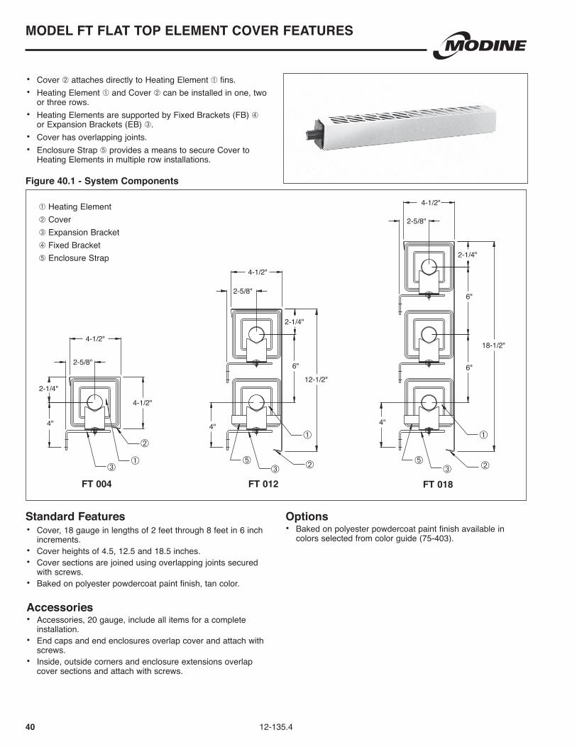
40 12-135.4
• Cover ➁ attaches directly to Heating Element ➀ fins .• Heating Element ➀ and Cover ➁ can be installed in one, two
or three rows .• Heating Elements are supported by Fixed Brackets (FB) ➃
or Expansion Brackets (EB) ➂ .• Cover has overlapping joints .• Enclosure Strap ➄ provides a means to secure Cover to
Heating Elements in multiple row installations .
6"
6"
6"
2-1/4"
2-5/8"
4-1/2"
2-1/4"
2-5/8"
4-1/2"
2-1/4"
2-5/8"
4-1/2"
4-1/2"
12-1/2"
18-1/2"
4"4" 4"
Standard Features• Cover, 18 gauge in lengths of 2 feet through 8 feet in 6 inch
increments .• Cover heights of 4 .5, 12 .5 and 18 .5 inches .• Cover sections are joined using overlapping joints secured
with screws .• Baked on polyester powdercoat paint finish, tan color .
Accessories• Accessories, 20 gauge, include all items for a complete
installation .• End caps and end enclosures overlap cover and attach with
screws .• Inside, outside corners and enclosure extensions overlap
cover sections and attach with screws .
Options• Baked on polyester powdercoat paint finish available in
colors selected from color guide (75-403) .
FT 004 FT 012 FT 018
MODEL FT FLAT TOP ELEMENT COVER FEATURES
➀ Heating Element➁ Cover➂ Expansion Bracket➃ Fixed Bracket➄ Enclosure Strap
Figure 40.1 - System Components
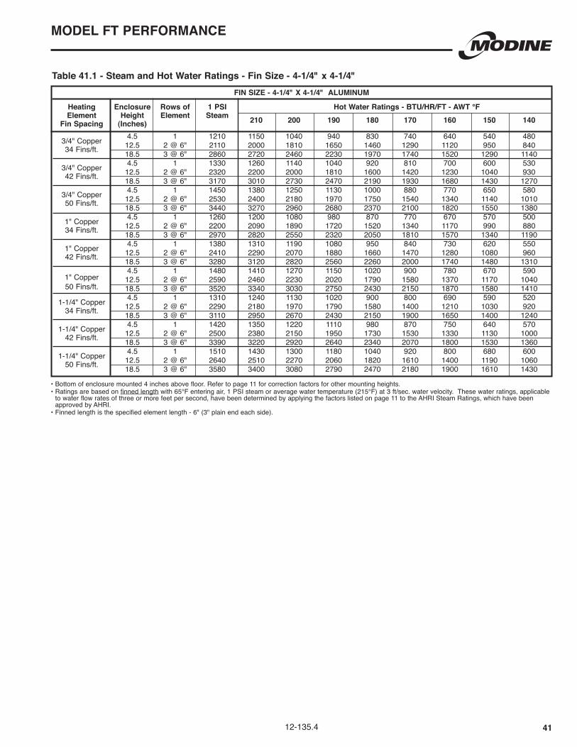
4112-135.4
• Bottom of enclosure mounted 4 inches above floor. Refer to page 11 for correction factors for other mounting heights.• Ratings are based on finned length with 65°F entering air, 1 PSI steam or average water temperature (215°F) at 3 ft/sec . water velocity . These water ratings, applicable
to water flow rates of three or more feet per second, have been determined by applying the factors listed on page 11 to the AHRI Steam Ratings, which have been approved by AHRI .
• Finned length is the specified element length - 6" (3" plain end each side).
Table 41.1 - Steam and Hot Water Ratings - Fin Size - 4-1/4" x 4-1/4"FIN SIZE - 4-1/4" x 4-1/4" ALUMINUM
Heating Enclosure Rows of 1 PSI Hot Water Ratings - BTU/HR/FT - AWT °F Element Height Element Steam Fin Spacing (Inches) 210 200 190 180 170 160 150 140
3/4" Copper 4 .5 1 1210 1150 1040 940 830 740 640 540 480 12 .5 2 @ 6" 2110 2000 1810 1650 1460 1290 1120 950 840 34 Fins/ft . 18 .5 3 @ 6" 2860 2720 2460 2230 1970 1740 1520 1290 1140 3/4" Copper 4 .5 1 1330 1260 1140 1040 920 810 700 600 530 12 .5 2 @ 6" 2320 2200 2000 1810 1600 1420 1230 1040 930 42 Fins/ft . 18 .5 3 @ 6" 3170 3010 2730 2470 2190 1930 1680 1430 1270 3/4" Copper 4 .5 1 1450 1380 1250 1130 1000 880 770 650 580 12 .5 2 @ 6" 2530 2400 2180 1970 1750 1540 1340 1140 1010 50 Fins/ft . 18 .5 3 @ 6" 3440 3270 2960 2680 2370 2100 1820 1550 1380 1" Copper 4 .5 1 1260 1200 1080 980 870 770 670 570 500 12 .5 2 @ 6" 2200 2090 1890 1720 1520 1340 1170 990 880 34 Fins/ft . 18 .5 3 @ 6" 2970 2820 2550 2320 2050 1810 1570 1340 1190 1" Copper 4 .5 1 1380 1310 1190 1080 950 840 730 620 550 12 .5 2 @ 6" 2410 2290 2070 1880 1660 1470 1280 1080 960 42 Fins/ft . 18 .5 3 @ 6" 3280 3120 2820 2560 2260 2000 1740 1480 1310
1" Copper 4 .5 1 1480 1410 1270 1150 1020 900 780 670 590
12 .5 2 @ 6" 2590 2460 2230 2020 1790 1580 1370 1170 1040 50 Fins/ft . 18 .5 3 @ 6" 3520 3340 3030 2750 2430 2150 1870 1580 1410
1-1/4" Copper 4 .5 1 1310 1240 1130 1020 900 800 690 590 520 12 .5 2 @ 6" 2290 2180 1970 1790 1580 1400 1210 1030 920 34 Fins/ft . 18 .5 3 @ 6" 3110 2950 2670 2430 2150 1900 1650 1400 1240 1-1/4" Copper 4 .5 1 1420 1350 1220 1110 980 870 750 640 570 12 .5 2 @ 6" 2500 2380 2150 1950 1730 1530 1330 1130 1000 42 Fins/ft . 18 .5 3 @ 6" 3390 3220 2920 2640 2340 2070 1800 1530 1360 1-1/4" Copper 4 .5 1 1510 1430 1300 1180 1040 920 800 680 600 12 .5 2 @ 6" 2640 2510 2270 2060 1820 1610 1400 1190 1060 50 Fins/ft . 18 .5 3 @ 6" 3580 3400 3080 2790 2470 2180 1900 1610 1430
MODEL FT PERFORMANCE

42 12-135.4
• Cover ➁ attaches directly to Heating Element ➀ fins .• Heating Element ➀ and Cover ➁ can be installed in one, two
or three rows .• Heating Elements are supported by Fixed Brackets (FB) ➃
or Expansion Brackets (EB) ➂ .• Cover has butting joints .• Enclosure Strap ➄ provides a means to secure Cover to
Heating Elements in multiple row installations .
6"
6"
6"
2-1/4"
2-5/8"
4-1/2"
2-1/4"
2-5/8"
4-1/2"
2-1/4"
2-5/8"
4-1/2"
4"
4-1/2"
12-1/2"
18-1/2"
4" 4"
Standard Features• Cover, 18 gauge in lengths of 2 feet through 8 feet in 6 inch
increments .• Cover heights of 4 .5, 12 .5 and 18 .5 inches .• Cover sections are joined using butt joints .• Baked on polyester powdercoat paint finish, tan color .
Accessories• Accessories, 20 gauge, include all items for a complete
installation .• End caps and end enclosures overlap cover and attach with
screws .• Inside, outside corners and enclosure extensions overlap
cover sections and attach with screws .
Options• Baked on polyester powdercoat paint finish available in
colors selected from color guide (75-403) .
EM 004 EM 012 EM 018
MODEL EM ExPANDED METAL ELEMENT COVER FEATURES
➀ Heating Element➁ Cover➂ Expansion Bracket➃ Fixed Bracket➄ Enclosure Strap
Figure 42.1 - System Components

4312-135.4
Table 43.1 - Steam and Hot Water Ratings - Fin Size - 4-1/4" x 4-1/4"FIN SIZE - 4-1/4" x 4-1/4" ALUMINUM
Heating Enclosure Rows of 1 PSI Hot Water Ratings - BTU/HR/FT - AWT °F Element Height Element Steam Fin Spacing (Inches) 210 200 190 180 170 160 150 140
3/4" Copper 4 .5 1 1310 1240 1130 1020 900 800 690 590 520 12 .5 2 @ 6" 2280 2170 1960 1780 1570 1390 1210 1030 910 34 Fins/ft . 18 .5 3 @ 6" 3080 2930 2650 2400 2130 1880 1630 1390 1230 3/4" Copper 4 .5 1 1430 1360 1230 1120 990 870 760 640 570 12 .5 2 @ 6" 2500 2380 2150 1950 1730 1530 1330 1130 1000 42 Fins/ft . 18 .5 3 @ 6" 3420 3250 2940 2670 2360 2090 1810 1540 1370 3/4" Copper 4 .5 1 1560 1480 1340 1220 1080 950 830 700 620 12 .5 2 @ 6" 2730 2590 2350 2130 1880 1670 1450 1230 1090 50 Fins/ft . 18 .5 3 @ 6" 3710 3520 3190 2890 2560 2260 1970 1670 1480 1" Copper 4 .5 1 1360 1290 1170 1060 940 830 720 610 540 12 .5 2 @ 6" 2370 2250 2040 1850 1640 1450 1260 1070 950 34 Fins/ft . 18 .5 3 @ 6" 3200 3040 2750 2500 2210 1950 1700 1440 1280 1" Copper 4 .5 1 1480 1410 1270 1150 1020 900 780 670 590 12 .5 2 @ 6" 2600 2470 2240 2030 1790 1590 1380 1170 1040 42 Fins/ft . 18 .5 3 @ 6" 3520 3340 3030 2750 2430 2150 1870 1580 1410 1" Copper 4 .5 1 1590 1510 1370 1240 1100 970 840 720 640 12 .5 2 @ 6" 2790 2650 2400 2180 1930 1700 1480 1260 1120 50 Fins/ft . 18 .5 3 @ 6" 3800 3610 3270 2960 2620 2320 2010 1710 1520 1-1/4" Copper 4 .5 1 1410 1340 1210 1100 970 860 750 630 560 12 .5 2 @ 6" 2470 2350 2120 1930 1700 1510 1310 1110 990 34 Fins/ft . 18 .5 3 @ 6" 3350 3180 2880 2610 2310 2040 1780 1510 1340 1-1/4" Copper 4 .5 1 1530 1450 1320 1190 1060 930 810 690 610 12 .5 2 @ 6" 2690 2560 2310 2100 1860 1640 1430 1210 1080 42 Fins/ft . 18 .5 3 @ 6" 3650 3470 3140 2850 2520 2230 1930 1640 1460 1-1/4" Copper 4 .5 1 1620 1540 1390 1260 1120 990 860 730 650 12 .5 2 @ 6" 2850 2710 2450 2220 1970 1740 1510 1280 1140 50 Fins/ft . 18 .5 3 @ 6" 3860 3670 3320 3010 2660 2350 2050 1740 1540
MODEL EM PERFORMANCE
• Bottom of enclosure mounted 4 inches above floor. Refer to page 11 for correction factors for other mounting heights.• Ratings are based on finned length with 65°F entering air, 1 PSI steam or average water temperature (215°F) at 3 ft/sec . water velocity . These water ratings, applicable
to water flow rates of three or more feet per second, have been determined by applying the factors listed on page 11 to the AHRI Steam Ratings, which have been approved by AHRI .
• Finned length is the specified element length - 6" (3" plain end each side).

44 12-135.4
• Copper Tube/Aluminum Fin .• Heating Element ➀ can be installed in one, two or three
rows .• Heating Elements are supported by Fixed Brackets (FB) ➂ or
Expansion Brackets (EB) ➁ .
6"
6"
6"
2-5/8"
2-5/8"
2-5/8"
4" 4" 4"
4-1/4"
4-1/4"
4-1/4"
4-1/4"
Copper Tube/Aluminum Fin• Lengths of 2 feet through 12 feet in 6 inch increments for
1-1/4" diameter . Lengths are 2 feet through 8 feet in 6 inch increments for 3/4" and 1" diameter .
• Aluminum fins are 4-1/4" x 4-1/4" x 0 .018" thick or 2-3/4" x 4-1/4" x 0 .018" thick .
• Fins/foot are 34, 42 or 50 .
1-ROW 2-ROW 3-ROW
Element Length**Includes 3" plain ends each side .
MODEL CP BARE HEATING ELEMENT FEATURES
➀ Heating Element➁ Expansion Bracket➂ Fixed Bracket
Figure 44.1 - System Components

4512-135.4
Table 45.1 - Steam and Hot Water Ratings - Fin Size - 4-1/4" x 4-1/4"
Table 45.2 - Steam and Hot Water Ratings - Fin Size - 2-3/4" x 4-1/4"
FIN SIZE - 4-1/4" x 4-1/4" ALUMINUM
Heating Mounting Rows of 1 PSI Hot Water Ratings - BTU/HR/FT - AWT °F Element Height Element Steam Fin Spacing (Inches) 210 200 190 180 170 160 150 140
3/4" Copper 9-1/4 1 1350 1280 1160 1050 930 820 720 610 540 15-1/4 2 @ 6" 2350 2230 2020 1830 1620 1430 1250 1060 940 34 Fins/ft . 21-1/4 3 @ 6" 3040 2890 2610 2370 2100 1850 1610 1370 1220 3/4" Copper 9-1/4 1 1480 1410 1270 1150 1020 900 780 670 590 15-1/4 2 @ 6" 2840 2700 2440 2220 1960 1730 1510 1280 1140 42 Fins/ft . 21-1/4 3 @ 6" 3720 3530 3200 2900 2570 2270 1970 1670 1490 3/4" Copper 9-1/4 1 1610 1530 1380 1260 1110 980 850 720 640 15-1/4 2 @ 6" 2820 2680 2430 2200 1950 1720 1490 1270 1130 50 Fins/ft . 21-1/4 3 @ 6" 3660 3480 3150 2850 2530 2230 1940 1650 1460 1" Copper 9-1/4 1 1400 1330 1200 1090 970 850 740 630 560 15-1/4 2 @ 6" 2440 2320 2100 1900 1680 1490 1290 1100 980 34 Fins/ft . 21-1/4 3 @ 6" 3150 2990 2710 2460 2170 1920 1670 1420 1260 1" Copper 9-1/4 1 1530 1450 1320 1190 1060 930 810 690 610 15-1/4 2 @ 6" 2770 2630 2380 2160 1910 1690 1470 1250 1110 42 Fins/ft . 21-1/4 3 @ 6" 3630 3450 3120 2830 2500 2210 1920 1630 1450 1" Copper 9-1/4 1 1640 1560 1410 1280 1130 1000 870 740 660 15-1/4 2 @ 6" 2880 2740 2480 2250 1990 1760 1530 1300 1150 50 Fins/ft . 21-1/4 3 @ 6" 3740 3550 3220 2920 2580 2280 1980 1680 1500 1-1/4" Copper 9-1/4 1 1450 1380 1250 1130 1000 880 770 650 580 15-1/4 2 @ 6" 2540 2410 2180 1980 1750 1550 1350 1140 1020 34 Fins/ft . 21-1/4 3 @ 6" 3330 3160 2860 2600 2300 2030 1760 1500 1330 1-1/4" Copper 9-1/4 1 1580 1500 1360 1230 1090 960 840 710 630 15-1/4 2 @ 6" 2690 2560 2310 2100 1860 1640 1430 1210 1080 42 Fins/ft . 21-1/4 3 @ 6" 3520 3340 3030 2750 2430 2150 1870 1580 1410 1-1/4" Copper 9-1/4 1 1670 1590 1440 1300 1150 1020 890 750 670 15-1/4 2 @ 6" 2670 2540 2300 2080 1840 1630 1420 1200 1070 50 Fins/ft . 21-1/4 3 @ 6" 3480 3310 2990 2710 2400 2120 1840 1570 1390
FIN SIZE - 2-3/4" x 4-1/4" ALUMINUM
Heating Mounting Rows of 1 PSI Hot Water Ratings - BTU/HR/FT - AWT °F Element Height Element Steam Fin Spacing (Inches) 210 200 190 180 170 160 150 140
3/4" Copper 6-3/4 1 1110 1050 950 870 770 680 590 500 440 12-3/4 2 @ 6" 1890 1800 1630 1470 1300 1150 1000 850 760 34 Fins/ft . 18-3/4 3 @ 6" 2480 2360 2130 1930 1710 1510 1310 1120 990 3/4" Copper 6-3/4 1 1250 1190 1080 980 860 760 660 560 500 12-3/4 2 @ 6" 2120 2010 1820 1650 1460 1290 1120 950 850 42 Fins/ft . 18-3/4 3 @ 6" 2790 2650 2400 2180 1930 1700 1480 1260 1120 3/4" Copper 6-3/4 1 1390 1320 1200 1080 960 850 740 630 560 12-3/4 2 @ 6" 2360 2240 2030 1840 1630 1440 1250 1060 940 50 Fins/ft . 18-3/4 3 @ 6" 3090 2940 2660 2410 2130 1880 1640 1390 1240 1" Copper 6-3/4 1 1110 1050 950 870 770 680 590 500 440 12-3/4 2 @ 6" 1880 1790 1620 1470 1300 1150 1000 850 750 34 Fins/ft . 18-3/4 3 @ 6" 2470 2350 2120 1930 1700 1510 1310 1110 990 1" Copper 6-3/4 1 1240 1180 1070 970 860 760 660 560 500 12-3/4 2 @ 6" 2100 2000 1810 1640 1450 1280 1110 950 840 42 Fins/ft . 18-3/4 3 @ 6" 2760 2620 2370 2150 1900 1680 1460 1240 1100 1" Copper 6-3/4 1 1370 1300 1180 1070 950 840 730 620 550 12-3/4 2 @ 6" 2330 2210 2000 1820 1610 1420 1230 1050 930 50 Fins/ft . 18-3/4 3 @ 6" 3060 2910 2630 2390 2110 1870 1620 1380 1220 1-1/4" Copper 6-3/4 1 1110 1050 950 870 770 680 590 500 440 12-3/4 2 @ 6" 1890 1800 1630 1470 1300 1150 1000 850 760 34 Fins/ft . 18-3/4 3 @ 6" 2480 2360 2130 1930 1710 1510 1310 1120 990 1-1/4" Copper 6-3/4 1 1230 1170 1060 960 850 750 650 550 490 12-3/4 2 @ 6" 2100 2000 1810 1640 1450 1280 1110 950 840 42 Fins/ft . 18-3/4 3 @ 6" 2740 2600 2360 2140 1890 1670 1450 1230 1100 1-1/4" Copper 6-3/4 1 1350 1280 1160 1050 930 820 720 610 540 12-3/4 2 @ 6" 2300 2190 1980 1790 1590 1400 1220 1040 920 50 Fins/ft . 18-3/4 3 @ 6" 3010 2860 2590 2350 2080 1840 1600 1350 1200
MODEL CP PERORMANCE
• Refer to page 11 for correction factors for other mounting heights. • Ratings are based on finned length with 65°F entering air, 1 PSI steam or average water temperature (215°F) at
3 ft/sec . water velocity These water ratings, applicable to water flow rates of three or more feet per second, have been determined by applying the factors listed on page 11 to the AHRI Steam Ratings, which have been approved by AHRI .
• Finned length is the specified element length - 6" (3" plain end each side).
Bold, italicized units are

46 12-135.4
FIN SIZE - 3-1/4" x 2-3/4" ALUMINUM Heating Rows of 1 PSI Hot Water Ratings - BTU/HR/FT - AWT °F Element Element Steam Fin Spacing 210 200 190 180 170 160 150 140 3/4" Copper 1 880 840 760 690 610 540 470 400 350 34 Fins/ft . 3/4" Copper 1 970 920 830 760 670 590 510 440 390 42 Fins/ft . 3/4" Copper 1 1050 1000 900 820 720 640 560 470 420 50 Fins/ft . 1" Copper 1 870 830 750 680 600 530 460 390 350 34 Fins/ft . 1" Copper 1 940 890 810 730 650 570 500 420 380 42 Fins/ft . 1" Copper 1 1020 970 880 800 700 620 540 460 410 50 Fins/ft . 1-1/4" Copper 1 850 810 730 660 590 520 450 380 340 34 Fins/ft . 1-1/4" Copper 1 920 870 790 720 630 560 490 410 370 42 Fins/ft . 1-1/4" Copper 1 990 940 850 770 680 600 520 450 400 50 Fins/ft .
• Refer to page 11 for correction factors for other mounting heights. • Ratings are based on finned length with 65°F entering air, 1 PSI steam or average water temperature (215°F) at 3 ft/sec . water velocity .
These water ratings, applicable to water flow rates of three or more feet per second, have been determined by applying the factors listed on page 11 to the AHRI Steam Ratings, which have been approved by AHRI .
• Finned length is the specified element length - 6" (3" plain end each side).
Table 46.1 - Steam and Hot Water Ratings - Fin Size - 3-1/4" x 2-3/4"
Table 46.2 - Steam and Hot Water Ratings - Fin Size - 4-1/4" x 2-3/4"FIN SIZE - 4-1/4" x 2-3/4" ALUMINUM
Heating Rows of 1 PSI Hot Water Ratings - BTU/HR/FT - AWT °F Element Element Steam Fin Spacing 210 200 190 180 170 160 150 140 3/4" Copper 1 1000 950 860 780 690 610 530 450 400 34 Fins/ft . 3/4" Copper 1 1140 1080 980 890 790 700 600 510 460 42 Fins/ft . 3/4" Copper 1 1280 1220 1100 1000 880 780 680 580 510 50 Fins/ft . 1" Copper 1 990 940 850 770 680 600 520 450 400 34 Fins/ft . 1" Copper 1 1120 1060 960 870 770 680 590 500 450 42 Fins/ft . 1" Copper 1 1250 1190 1080 980 860 760 660 560 500 50 Fins/ft . 1-1/4" Copper 1 960 910 830 750 660 590 510 430 380 34 Fins/ft . 1-1/4" Copper 1 1080 1030 930 840 750 660 570 490 430 42 Fins/ft . 1-1/4" Copper 1 1200 1140 1030 940 830 730 640 540 480 50 Fins/ft .
MODEL CP PERFORMANCE

4712-135.4
Heating ElementsCopper tube/Aluminum fin elements are available in 3/4, 1, and 1-1/4 inch outer diameter seamless copper tubing . Fins are either 2-3/4 x 3-1/4, 2-3/4 x 4-1/4, or 4-1/4 x 4-1/4 inches with 34, 42, or 50 fins/ft ., and are unpainted and bonded to the tube by mechanical expansion of the tube . Maximum element length is 8 feet for 3/4 and 1 inch diameter tubes and 12 feet for 1-1/4 inch diameter tubes . Maximum working pressure at 300° F is 250 psi for 3/4 inch tubes, 185 psi for 1 inch tube and 190 psi for 1-1/4 inch tubes .
Hangers and SupportsEnclosure wall supports attach to the 20 gauge aluminized steel hanger strip . Enclosure wall supports may be placed at any location along the hanger strip allowing installation directly over wall supports .
One fastener is required for each enclosure wall support in order to properly secure it .
Enclosure wall supports have a V-bend at the bottom which fully engages the enclosure and supports its weight .
Element support assembly and return pipe hangers hook into the wall support “pegboard style” .
Enclosure and element supports are die-formed in 16 gauge galvanized steel with integral stiffening ribs . All return pipe hangers are wire formed for ease of adjustment . No fasteners or sub-assembly are required for any element or return pipe support .
Element support cradles give two-point support to the element and allow over 2-1/2 inches of lateral movement . Cradles slide on full bearing polymeric discs and are held in place with a polymeric rivet .
Fin Tube EnclosuresAll standard Commercial enclosures are manufactured in 18 gauge (14 gauge for model PS) cold-rolled steel . Enclosure lengths range from 2 feet to 8 feet in 6 inch increments .
Air discharge louver banks are 3 inches on center and have a “pencil proof” design .
All standard enclosures have a tan color, baked-on polyester powdercoat paint finish, which may be used as a final coat or repainted .
All enclosure styles include interlocking slip-joints for smooth hairline joints, with no fasteners required . All friction clips and back-up strips include stiffening angles for added reinforcement at all enclosure joints .
Fin Tube Element CoversTypes FT and EM element covers overlap and clip over the fin area of the element . No hanger strip is required . The element must be supported by either a fixed bracket (FB) or expansion bracket (EB) .
All covers are made of 18 gauge steel and are finished in tan baked on polyester powdercoat paint finish . Type EM covers butt together . Type FT covers overlap one another . Cover straps are available for use with multiple rows of element, to secure the cover to the lower row of element .
AccessoriesAccessories are manufactured in either 14, 18, or 20 gauge cold-rolled steel, depending on the piece . Accessories are cleaned, phosphatized, and finished with a baked on polyester powdercoat paint finish to match enclosures . Valve compartments, end caps, and end enclosures have slip joints to attach to the end of the enclosure . Corners and extensions are telescoping and overlap adjacent corners . They incorporate fold-over tabs to secure the accessory to the enclosure without fasteners, except for model PS accessories which attach to the enclosure with tamperproof fasteners .
SPECIFICATIONS

Products from Modine are designed to provide indoor air-comfort and ventilation solutions for residential, commercial, institutional and industrial applications. Whatever your heating, ventilating and air conditioning requirements, Modine has the product to satisfy your needs, including:
HVAC
• Unit Heaters:
– Gas
– Hydronic
– Electric
– Oil
• Ceiling Cassettes
• Duct Furnaces
• Hydronic Cabinet Unit Heaters, Fin Tube, Convectors
• Infrared Heaters
• Make-up Air Systems
• Unit Ventilators
Ventilation
• Packaged Rooftop Ventilation
School Products
• Vertical Packaged Classroom HVAC:
– DX Cooling/Heat Pump
– Water/Ground Source Heat Pump
– Horizontal/Vertical Unit Ventilators
Geothermal
• Water-to-Water
• Water-to-Air
• Combination Specific catalogs are available for each product. Catalogs 75-136 and 75-137 provide details on all Modine HVAC equipment.
Modine Manufacturing Company
1500 DeKoven Avenue
Racine, Wisconsin 53403-2552
Phone: 1.800.828.4328 (HEAT)
www.modinehvac.com
© Modine Manufacturing Company 2014
The Modine brand has been the
industry standard since Arthur B.
Modine invented and patented
the first lightweight, suspended
hydronic unit heater in 1923.
No other manufacturer can
provide the combined application
flexibility, technical expertise and
fast delivery found at Modine.
Consult your local Modine
distributor for help in solving your
indoor air problems.

![RSPAMD - Heinlein Support...Rspamd - neue Konzepte im Antispam [SLAC 2019] Carsten Rosenberg Rspamd – Symbols and Scores Every function registers](https://static.documents.pub/doc/80x56/5f09a9ad7e708231d427ea5b/rspamd-heinlein-support-rspamd-neue-konzepte-im-antispam-slac-2019-carsten.jpg)

![Ioakimidis,Demetre-[Le livre d'or de la science-fiction-24]Heinlein(1981).OCR.French.ebook.AlexandriZ.pdf](https://static.documents.pub/doc/80x56/55cf9b32550346d033a515ca/ioakimidisdemetre-le-livre-dor-de-la-science-fiction-24heinlein1981ocrfrenchebookalexandrizpdf.jpg)


