19
Commercial gas range 17 – 1890kW Commercial gas range Range: 17 – 1890kW TECHNICAL INFORMATION
Commercial gas range17 – 1890kW
Commercial gas rangeRange: 17 – 1890kW
TEC
HN
ICA
L IN
FORM
ATI
ON
2 3
Commercial gas range
ELCO provides one of the fi nest ranges of condensing gas boilers and CHP units on the market.
ELCO Heating Solutions 2
Range overview 4
Robustness 6
High effi ciency 8
Effi ciency and emissions 10
Modular construction 12
Low water content 14
Applications 16
Connectivity 18
THISION® L EVO 19
TRIGON® XL 23
R3400 – R3600 27
VARION® C-POWER 31
Full range of accessories 35
ContentsELCO Heating Solutions
More information:www.elco.co.uk
A full range of application engineering and customised solutions for commercial installations. Plus, ELCO offers complete peace of mind with a range of services, including:
• Maintenance contracts
• Extended warranties
• Start up/Commissioning
• Connectivity
• Repairs
• System upgrade
Applications and services
Get started
This extensive brochure explains the technology and engineering utilised in ELCO's comprehensive manufacturing processes, as well as the superb features incorporated into each product.
From a straightforward replacement, to the most complex commercial system, specifi ers can choose the right ELCO product for the application.
Commercial
Ren
ewab
les
HIU
Hot
wat
erG
asO
ilA
cces
sori
es
Air source heat pumps – outdoorGround source heat pumps – outdoorSolar thermal – tubes
Gas fi red condensing water heaters – instantaneous
Gas fi red condensing water heaters – storage
Cylinders – 80-3,000L
Gas condensing boilers – wall mountedGas condensing boilers – fl oor standingCombined heat and power units (CHP)
Heat interface units – direct and indirectHeat interface units – storageCooling units
Oil condensing boilers – fl oor standing
Controls, fl ue gas systems and pressurisation units

4 5
ELCO commercial gas boilers – overview
TRIGON® XLVARION® C-POWER R3400 - R3600THISION® L EVO
4 5
PRODUCT RANGE OUTPUT RANGE
Single Cascade XX XX XX
60 – 140kW
2 – 50kWel / 5 – 100kWth
150 – 575kW
600 – 1,890kW
120 – 1,100kWTHISION® L EVO
300 – 4,600kWTRIGON® XL
1.2 – 15MWR3400 – R3600
10 – 150kWel / 24 – 300kWth
XXXX
VARION® C-POWER
TYPICAL APPLICATION
• High effi ciency• Low emissions• Intelligent controls• Cascade systems
up to 1.1MW• Seasonal effi ciency
up to 109.4%
Page 19
• High effi ciency• Low emissions• Intelligent controls• Compact design• Super silent• Seasonal effi ciency
up to 109.5%
• High effi ciency• Low emissions• Modular concept• Intelligent controls• Compact design• Cascade systems
up to 4.6MW• Seasonal effi ciency
up to 110.4%
• High effi ciency• Low emissions• Modular concept• Intelligent controls• Compact design• Cascade systems
up to 15MW• Seasonal effi ciency
up to 109.8%
Page 35 Page 23 Page 27
2 – 50kWel
5 – 100kWth
150 – 575kW
600 – 1,890kW
60 – 140kW
Multi family house Budget – 3 star hotel 4 – 5 star hotel + wellness Hospital Swimming pool Sports facility Offi ces Industry

6 7
Robustness – stainless steel heat exchangers for tough conditions
Flue gas side
ELCO utilises high grade stainless steel on its heat exchangers to resist corrosion from fl ue gas condensate – enhancing a boiler's durability and longevity.
Water side
The water quality in a system is of high importance when optimising effi ciency and long term performance of heating equipment. One of the key factors to consider is the pH value.
The potential problems
If water quality is not maintained at the correct pH level (7 to 8.5), there is a high risk of the pipework corroding, or scale forming on the internal surface.
The pH of water
Soft water has a low pH value and can cause corrosion within the system due to the presence of hydrogen molecules. In hard water areas, scaling can form on the inside of the system pipework.
The combustion of gas and air
Due to impurities in gas and air, the combustion process produces acids. However, at high temperatures, there is limited impact from corrosion due to the lack of water present.
Stainless steel heat exchanger
Stainless steel is the preferred material for heat exchangers as it is far more resistant to corrosion than other metals.
50
Alkalinity (mg/L CaCO3)
06
6.5
7
7.5
8
8.5
pH
Val
ues
9
9.5
10
100 150 200 250 300 350
Hard water(scale forming region)
Soft water(corrosion region)
Acidic
1 2 3 4 5 6 7 8 9 10 11 12
Alkaline
Battery acid Vinegar
2.9 - 4.0Flue gas condensate
Typical householdsewage
Lemonjuice
Rainwater Distilled
water(neutral)
Clean rain
water
Tap water
Lake waterAmmonia
Gastric acid
25
Return water temperature (ºC)
Increasingcondensation
Point ofcondensation
Bo
iler
effic
ienc
y (%
)St
ead
y st
ate
/ Fu
ll fir
e
80
85
90
95
100
40 50 60 70 80
Water quality
The quality of water within a heating system is rarely stable, with pH values likely to increase over time and also cause corrosion.
Condensing boiler effi ciency
Below the point of condensation (57.2ºC at 10% excess air) where condensate is present, dissolved sulphuric and nitric acids can corrode the heat exchanger material.
Nitricacid
Sulphuricacid
Heating fl ow
Waste gas
Condensation drain
Heating return
Heating fl ow
Condensation drain
Heating return
Natural gas
Air

8 9
Stainless steel for high effi ciency
A unique robotised laser welding process
ELCO utilises the latest laser welding technology to ensure its stainless steel heat exchangers provide best in class effi ciencies,excellent reliability and unbeatable performance over their lifetime.
Overall heat transfer vs. exposure time
Stainless steel vs. other metals
Although a stainless steel heat exchanger starts its life cycle with a lower heat transfer rate, the material is far more effi cient over its entire lifetime – performing better for longer.
Aluminium Stainlesssteel
5
2 4 6
% Chromium
Scal
ing
& w
eig
ht lo
ss
8 10 12 14 16 18 20 22 24
10
15
20
25
30
35
40
4550
Effect of chromium content on scaling resistance (at 1,800ºF or 963ºC)
Stainless steel consists of iron and at least 11% chromium. If enough chromium is added, a protective passive fi lm will form to protect the metal from corrosion.
Aluminium
Other metals, such as aluminium, also produce a protective oxide layer. However, in the presence of moisture and high temperatures a porous oxide/hydroxide layer can form – reducing scale resistance and increasing risk of corrosion.
Days 100200
300400
500600
800
600
400
200
0
Ove
rall
hea
t tra
nsfe
r ra
tes
Stainless steel
A passive fi lm of chromium oxide (10nm thick) prevents any corrosive attack, ensuring surfaces remain smooth and bright. This eliminates the accumulation of fouling and deposits.
Crevice-free weld
A thin weld seam between the fi n edge and tube allows extremely fast heat transfer, while providing long term material stability.
Deformed material
Due to the material deforming from standard welding, heat up times are far slower, reducing overall effi ciency and product longevity.
Deformed material
A standard welded joint
250
Temp. (ºC)
240
220
210
45
260
Temp. (ºC)
220
150
115
105
Crevice-free weld
A laser welded joint
250
Temp. (ºC)
240
220
210
45
260
Temp. (ºC)
220
150
115
105

10 11
Effi ciency and emissions – experts in combustion technology
Water cooled heat exchanger
By cleverly channelling water through the heat exchanger walls, the combustion chamber is effectively cooled without the need for insulation.
Furthermore, this process allows additional energy to be recovered and transferred to the heating water – increasing boiler effi ciency and reducing radiation losses.
Low emissions
A water-cooled cold fl ame burner, combined with an optimised combustion zone, achieve extremely low NOx and CO emissions, which already comply with future NOx class 6 requirements.
Heat exchanger geometry
ELCO's state-of-the-art heat exchangers have a unique geometry, providing reliable and robust performance. They are all specifi cally designed for optimised effi ciency and functionality during their entire lifetime.
Optimised heat transfer
The cooling tube expands into the heat exchanger wall and provides an enhanced surface contact, which maximises heat transfer.
Hydroforming process
To maximise heat extraction throughout the cooling tubes, hydroforming technology isused during manufacturing.
This specialised process, which is popular in the automotive industry, consists of the cooling tubes being fi xed in place under the infl uence of a highly pressurised fl uid. This increases the diameter of the tube and forms a perfect seal.
Before After
12 1312 13
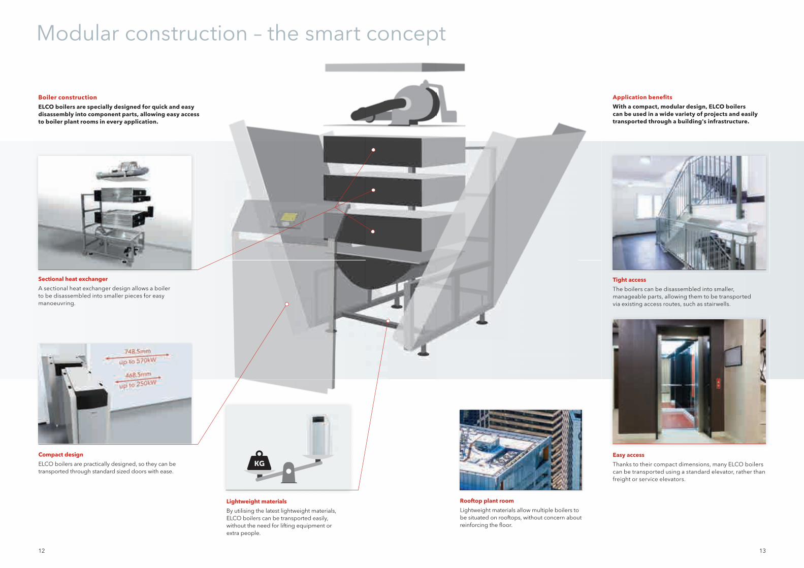
Modular construction – the smart concept
Boiler construction
ELCO boilers are specially designed for quick and easy disassembly into component parts, allowing easy access to boiler plant rooms in every application.
Application benefi ts
With a compact, modular design, ELCO boilers can be used in a wide variety of projects and easily transported through a building's infrastructure.
Lightweight materials
By utilising the latest lightweight materials, ELCO boilers can be transported easily, without the need for lifting equipment or extra people.
Easy access
Thanks to their compact dimensions, many ELCO boilers can be transported using a standard elevator, rather than freight or service elevators.
Compact design
ELCO boilers are practically designed, so they can be transported through standard sized doors with ease.
Rooftop plant room
Lightweight materials allow multiple boilers to be situated on rooftops, without concern about reinforcing the fl oor.
Tight access
The boilers can be disassembled into smaller, manageable parts, allowing them to be transported via existing access routes, such as stairwells.
Sectional heat exchanger
A sectional heat exchanger design allows a boiler to be disassembled into smaller pieces for easy manoeuvring.

14 15
Installation costs
When all aspects of an installation – such as transport, connections, pumps and low loss headers – are considered, a low water content unit offers substantial savings on installation time.
Energy consumption
With considerable differences in gas consumption and start up/stand still losses, low water content boilers deliver huge lifetime savings.
Calculation is based on a reference project with 800kW power.
= 5 man hours
Low water content – winning the effi ciency race
0ºC 20ºC 40ºC 60ºC 80ºC
Low water content
0º – 80ºC30 seconds
High water content
0º – 80ºC280 seconds
LWC boiler: 27 man hours
TOTAL SAVING: OVER 50%
HWC boiler: 64 man hours
Fast and furious
ELCO's state-of-the-art low water content boilers are capable of adapting to the changing demands of every application. A low water volume allows the units to respond rapidly to the changing temperature demand from the system and provide a perfect hydraulic balance – even in more complex installations when combined with other heat sources.
Light and robust
The low water content design allows ELCO heat exchangers to be mechanically decoupled, using fl exible seals and gaskets.
Compared to units which have one completely cast or welded sections, ELCO boilers are specifi cally designed to handle thermal stress when heating up and cooling down, even at higher temperature differentials.
O-ring
Space for movement
HWC boiler LWC boiler
PO
UN
DS
OV
ER
20
YE
AR
S
TOTAL SAVING:
£46,000
Start up losses (5K)
Start up losses (2 x heat up)
Gas consumption
Stand still losses
Electrical energy
16 17
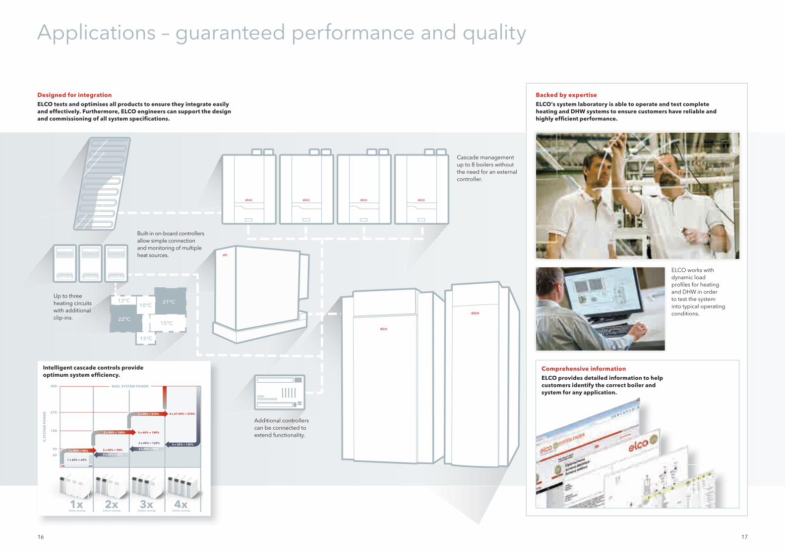
Applications – guaranteed performance and quality
Designed for integration
ELCO tests and optimises all products to ensure they integrate easily and effectively. Furthermore, ELCO engineers can support the design and commissioning of all system specifi cations.
Backed by expertise
ELCO‘s system laboratory is able to operate and test complete heating and DHW systems to ensure customers have reliable and highly effi cient performance.
ELCO works with dynamic load profi les for heating and DHW in order to test the system into typical operating conditions.
Comprehensive information
ELCO provides detailed information to help customers identify the correct boiler and system for any application.
Additional controllers can be connected to extend functionality.
21ºC
22ºC
12ºC
15ºC
15ºC
10ºC
60
90
180
270
400
% S
YST
EM
PO
WE
R
MAX. SYSTEM POWER
3 x 60% = 180%
4 x 67.50% = 270%
1xboiler running
2xboilers running
3xboilers running
4xboilers running
ON OFF
1 x 60% = 60%
1 x 90% = 90% 2 x 45% = 90%
2 x 30% = 60%
2 x 90% = 180%
3 x 90% = 270%
3 x 40% = 120%
3 x 30% = 90%
4 x 30% = 120%
Cascade management up to 8 boilers without the need for an external controller.
Built-in on-board controllers allow simple connection and monitoring of multiple heat sources.
Up to three heating circuits with additional clip-ins.
Intelligent cascade controls provide optimum system effi ciency.
18 19
THISION® L EVOConnectivity
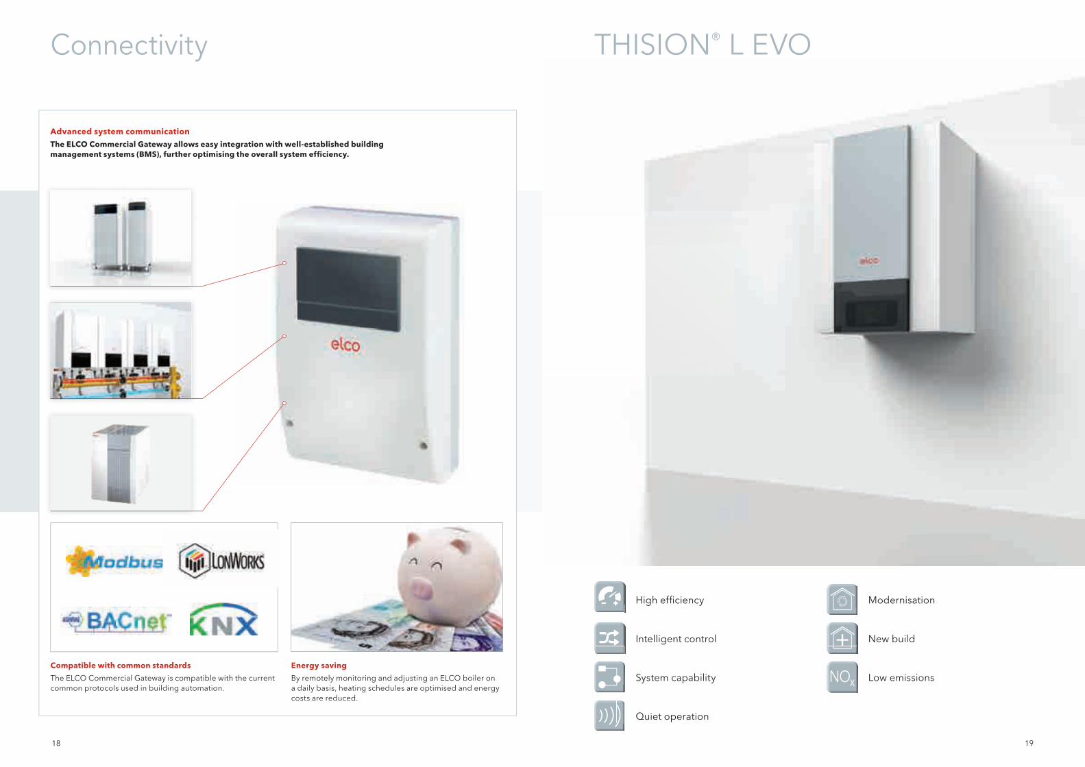
Energy saving
By remotely monitoring and adjusting an ELCO boiler on a daily basis, heating schedules are optimised and energy costs are reduced.
Compatible with common standards
The ELCO Commercial Gateway is compatible with the current common protocols used in building automation.
High effi ciency Modernisation
Intelligent control New build
System capability Low emissions
Quiet operation
Advanced system communication
The ELCO Commercial Gateway allows easy integration with well-established building management systems (BMS), further optimising the overall system effi ciency.

20 21
THISION® L EVO – Stunning fl exibility in every application
20 21
30ºC (30K) fl ow/return temperature differentialAn improved temperature differential allows easier integration with district heating systems while maintaining optimum effi ciency.
8 bar max water pressure With an enhanced capacity to supply heating and hot water to higher buildings, there is no need for hydraulic system separation.
Comprehensive control features A clear text display with integrated master-slave cascade functionality makes commissioning simple. Plus, an upgraded module capacity provides straightforward connections for additional heating zones, solar system or external heat sources.
ΔT 30K
Cascade packages In line and back-to-back arrangements facilitate quick installation of systems up to 1.1MW — even in limited plant room spaces. They also provide inherent back up and system security.
Low auxiliary energy consumptionAn extremely low resistance within the heat exchanger’s geometry ensures less than 0.15kW of electrical energy is needed to run a 140kW boiler at full load.
Double helix coilMinimum hydraulic resistance provides signifi cant reduction in electrical energy usage by the boiler pump.
Robust heat exchanger with double-wall geometrySuperb heat transfer at both full and partial load, achieving a fl ue gas temperature only 2ºC above the return temperature at full load. A stainless steel construction also maintains effi ciencies for the lifetime of the boiler.
22
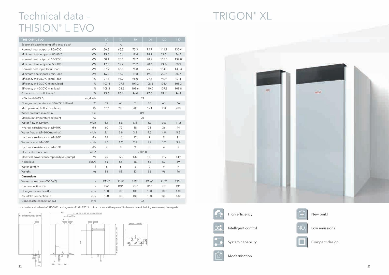
Technical data –THISION® L EVO
THISION® L EVO 60 70 80 100 120 140
Seasonal space heating effi ciency class* - A A - - - -
Nominal heat output at 80/60ºC kW 56.5 65.5 75.3 92.9 111.9 130.4
Minimum heat output at 80/60ºC kW 15.5 15.6 19.4 18.7 22.5 26.2
Nominal heat output at 50/30ºC kW 60.4 70.0 79.7 98.9 118.5 137.8
Minimum heat output at 50/30ºC kW 17.2 17.2 21.2 20.6 24.8 28.9
Nominal heat input Hi full load kW 57.9 66.8 76.8 95.2 114.3 133.3
Minimum heat input Hi min. load kW 16.0 16.0 19.8 19.0 22.9 26.7
Effi ciency at 80/60ºC Hi full load % 97.6 98.0 98.0 97.6 97.9 97.8
Effi ciency at 50/30ºC Hi min. load % 107.4 107.3 107.2 108.5 108.4 108.3
Effi ciency at 40/30ºC min. load % 108.3 108.5 108.6 110.0 109.9 109.8
Gross seasonal effi ciency** % 95.6 96.1 96.0 97.0 97.1 96.8
NOx level @ 0% 02 mg/kWh 39
Flue gas temperature at 80/60ºC full load ºC 59 60 61 60 63 66
Max. permissible fl ue resistance Pa 167 200 200 173 134 200
Water pressure max./min. bar 8/1
Maximum temperature setpoint ºC 90
Water flow at ∆T=10K m3/h 4.8 5.6 6.4 8.0 9.6 11.2
Hydraulic resistance at ∆T=10K kPa 60 72 88 28 36 44
Water flow at ∆T=20K (nominal) m3/h 2.4 2.8 3.2 4.0 4.8 5.6
Hydraulic resistance at ∆T=20K kPa 15 18 22 7 9 11
Water flow at ∆T=30K m3/h 1.6 1.9 2.1 2.7 3.2 3.7
Hydraulic resistance at ∆T=30K kPa 7 8 9 3 4 5
Electrical connection V/HZ 230/50
Electrical power consumption (excl. pump) W 96 122 130 131 119 149
Noise level dB(A) 55 55 56 62 57 59
Water content l 6 6 6 9 9 9
Weight kg 83 83 83 96 96 96
DimensionsWater connections (W1/W2) - R1¼ “ R1¼ “ R1¼ “ R1½ “ R1½ “ R1½ “
Gas connection (G) - R¾ “ R¾ “ R¾ “ R1“ R1“ R1“
Flue gas connection (F) mm 100 100 100 100 100 130
Air intake connection (A) mm 100 100 100 100 100 130
Condensate connection (C) mm 22
630 140 (60, 70, 80, 100, 120) or 190 (140)
A
W1 W2G
C
F
100
153 162 162
81
605
74
154
638
810
(60,
70 &
80)
or
950
(100
,120
& 1
40)
115 (60, 70, 80, 100, 120) or 130 (140)
23
High effi ciency New build
Intelligent control Low emissions
System capability Compact design
Modernisation
TRIGON® XL
*In accordance with directive 2010/30/EU and regulation (EU) 813/2013 **In accordance with equation 2 in the non-domestic building services compliance guide
24 25
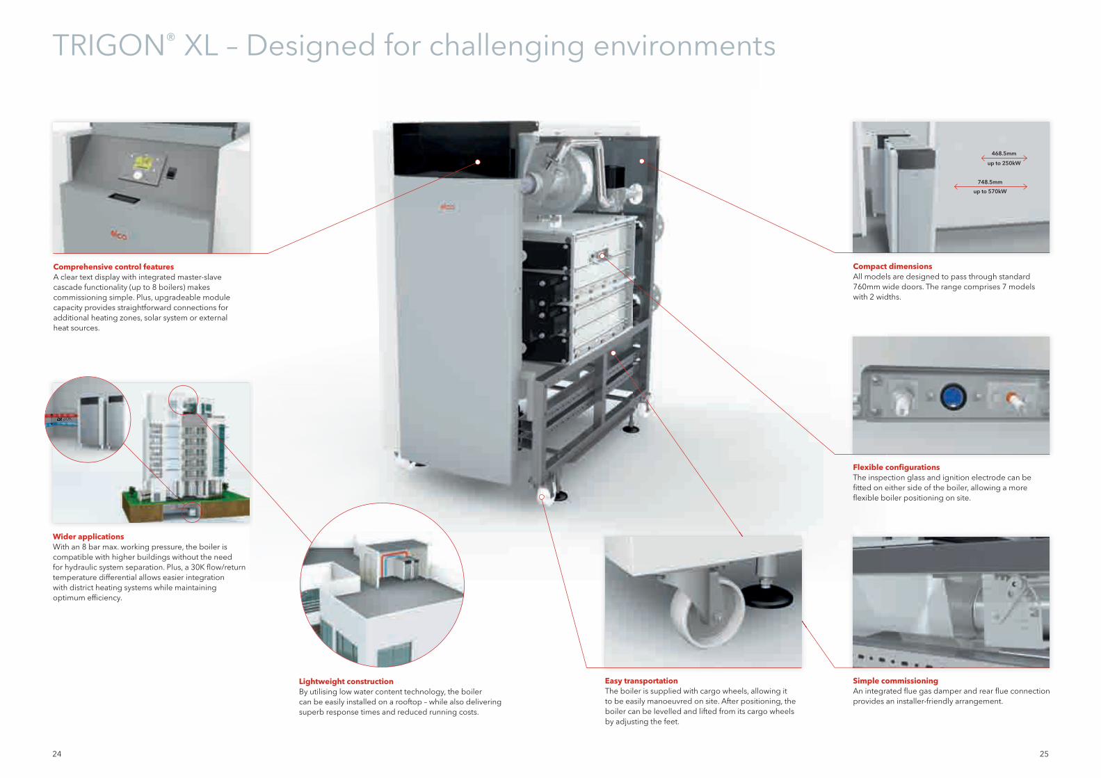
Comprehensive control featuresA clear text display with integrated master-slavecascade functionality (up to 8 boilers) makes commissioning simple. Plus, upgradeable module capacity provides straightforward connections for additional heating zones, solar system or external heat sources.
Compact dimensions All models are designed to pass through standard 760mm wide doors. The range comprises 7 models with 2 widths.
Flexible confi gurationsThe inspection glass and ignition electrode can be fi tted on either side of the boiler, allowing a more fl exible boiler positioning on site.
Easy transportationThe boiler is supplied with cargo wheels, allowing it to be easily manoeuvred on site. After positioning, the boiler can be levelled and lifted from its cargo wheels by adjusting the feet.
Simple commissioningAn integrated fl ue gas damper and rear fl ue connection provides an installer-friendly arrangement.
Wider applicationsWith an 8 bar max. working pressure, the boiler is compatible with higher buildings without the need for hydraulic system separation. Plus, a 30K fl ow/return temperature differential allows easier integration with district heating systems while maintaining optimum effi ciency.
Lightweight constructionBy utilising low water content technology, the boiler can be easily installed on a rooftop – while also delivering superb response times and reduced running costs.
∆t 30K∆t 30K
748.5mm
up to 570kW
468.5mm
up to 250kW
TRIGON® XL – Designed for challenging environments
26 27
Technical data – TRIGON® XL
R3400 – R3600
L1
L2 128
G A
S
0
178
490
601
967
1156 1131
D
10
374.2
W1
W2 147
0 1
460
748.5
L1
L2
10
145
5 1
466
G
W1
W2
A
S
131 105
234
0
178
482
1130
602
968 1124
D
468.5
TRIGON® XL 150 200 250 300 400 500 570
Nominal heat output at 80/60 ºC kW 142.3 190.4 237.6 285.7 381.3 476.7 540.2
Minimum heat output at 80/60 ºC kW 31.3 42.0 47.0 56.5 75.2 94.6 120.0
Nominal heat output at 50/30 ºC kW 149.4 199.9 249.7 300.3 401.1 503.2 572.8
Minimum heat output at 50/30 ºC kW 35.1 47.0 52.9 63.6 85.0 106.1 133.4
Nominal heat input Hi full load kW 145.0 194.0 242.0 291.0 388.0 485.0 550.0
Minimum heat input Hi min. load kW 32.2 43.1 48.4 58.2 77.6 97.0 122.2
Effi ciency at 80/60 ºC full load % 98.2 98.2 98.2 98.2 98.3 98.3 98.2
Effi ciency at 50/30 ºC min. load % 109.2 109.2 109.4 109.4 109.5 109.4 109.2
Effi ciency at 40/30 ºC min. load % 110.0 110.0 110.3 110.3 110.3 110.3 110.5
Gross seasonal effi ciency* % 97.1 97.1 97.3 97.3 97.3 97.3 97.5
NOx level @ 0% 02 mg/kWh 38 38 36 36 34 37 40
Flue gas temperature at 80/60 ºC full load ºC 75 75 75 75 75 75 76
Max. permissible fl ue resistance Pa 200 200 200 160 400 300 400
Water pressure max./min. bar 8/1 8/1 8/1 8/1 8/1 8/1 8/1
Maximum temperature setpoint ºC 90 90 90 90 90 90 90
Water flow at ∆T=10K m³/h 12.1 16.2 20.3 24.4 32.5 40.8 46.1
Hydraulic resistance at ∆T=10K kPa 45 107 125 48 129 137 228
Water flow at ∆T=20K m³/h 6.1 8.1 10.1 12.2 16.3 20.3 23.1
Hydraulic resistance at ∆T=20K kPa 11 27 31 12 32 34 57
Water flow at ∆T=30K m³/h 4.0 5.4 6.8 8.1 10.8 13.6 15.4
Hydraulic resistance at ∆T=30K kPa 5 12 14 5 14 15 25
Electrical connection V 230/400 230/400 230/400 230/400 230/400 230/400 230/400
Electrical power consumption (excl. pump) W 176 267 286 230 504 620 676
Noise level dB(A) 70.3 70.3 70.3 70.3 77.3 77.3 77.3
Water content l 27 31 35 61 68 75 82
Weight (empty) kg 290 332 336 434 496 540 595
Dimensions
Water connections (W1/W2) – R2“ R2“ R2“DN65 PN16
DN65 PN16
DN65 PN16
DN65 PN16
Gas connection (G) – R1½ “ R1½ “ R1½ “ R1½ “ R1½ “ R2“ R2“
Flue gas connection (D) mm 150 150 200 200 250 250 250
Air intake connection (A) (for room sealed use) mm 130 130 130 130 130 150 150
Condensate connection (S) mm 32 32 32 32 32 32 32
Boiler length with water connection (L1) mm 1349 1499 1649 1348 1496 1646 1769
Boiler length without water connection (L2) mm 1165 1315 1465 1152 1302 1452 1602
TRIGON® XL 150, 200 & 250 TRIGON® XL 300, 400, 500 & 570
High effi ciency New build
Intelligent control Low emissions
System capability Compact design
Modernisation
* In accordance with equation 2 in the non-domestic building services compliance guide
28 29
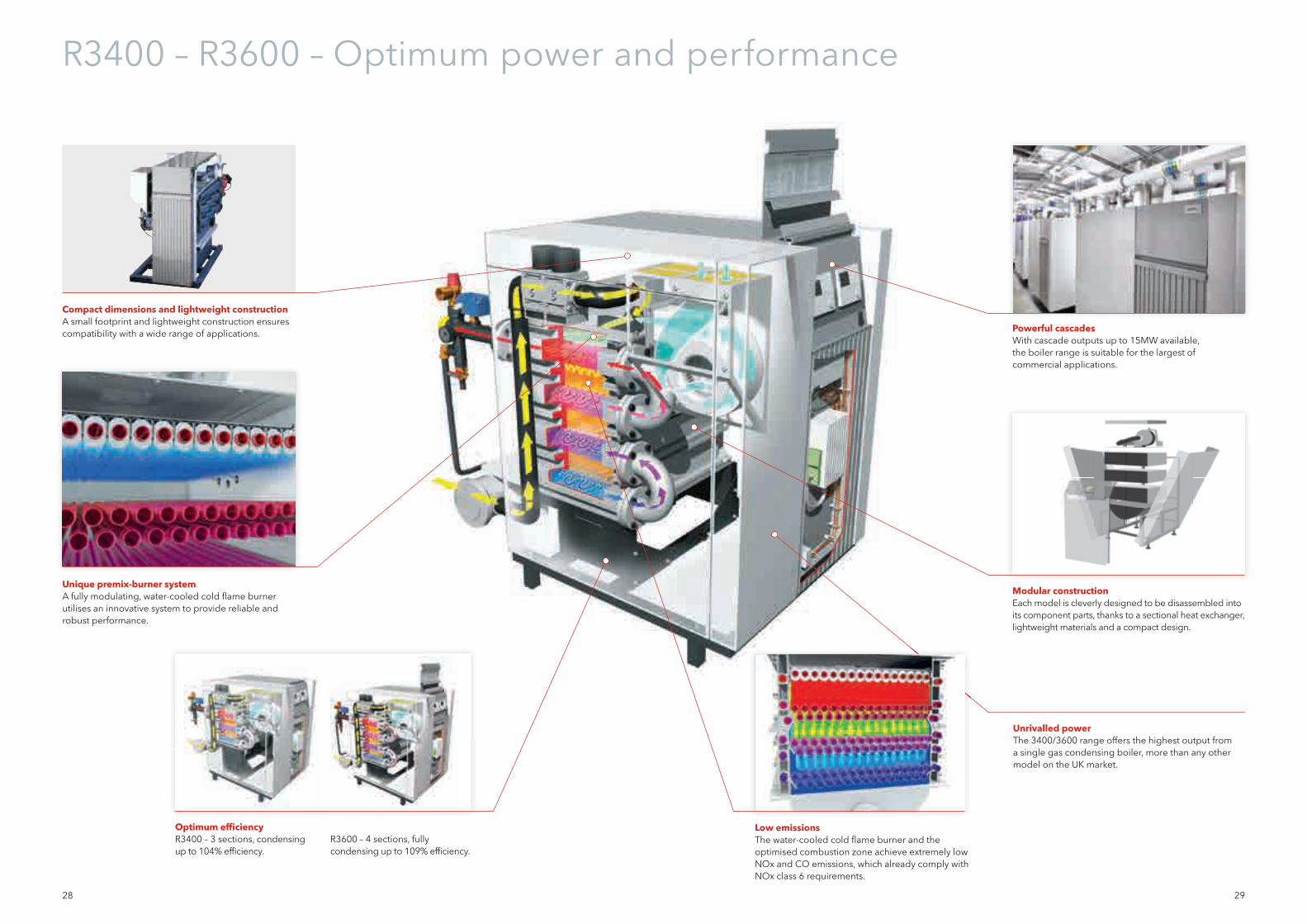
Powerful cascadesWith cascade outputs up to 15MW available, the boiler range is suitable for the largest of commercial applications.
Modular constructionEach model is cleverly designed to be disassembled into its component parts, thanks to a sectional heat exchanger, lightweight materials and a compact design.
Compact dimensions and lightweight constructionA small footprint and lightweight construction ensures compatibility with a wide range of applications.
Unique premix-burner systemA fully modulating, water-cooled cold fl ame burner utilises an innovative system to provide reliable and robust performance.
Low emissionsThe water-cooled cold fl ame burner and the optimised combustion zone achieve extremely low NOx and CO emissions, which already comply with NOx class 6 requirements.
R3400 – R3600 – Optimum power and performance
Optimum effi ciencyR3400 – 3 sections, condensing up to 104% effi ciency.
R3600 – 4 sections, fully condensing up to 109% effi ciency.
Unrivalled powerThe 3400/3600 range offers the highest output from a single gas condensing boiler, more than any other model on the UK market.

30 31
VARION® C-POWERTechnical data – R3400 / R3600
High effi ciency Modernisation
Remote control New build
System capability Compact design
Quiet operation*In accordance with equation 2 in the non-domestic building services compliance guide
R3400 R3401 R3403 R3404 R3406 R3407 R3408 R3410
Nominal heat output at 80/60 ºC kW 656.4 857.4 970.5 1195.9 1309.0 1496.0 1870.0
Minimum heat output at 80/60 ºC kW 164.0 213.4 242.3 298.2 326.2 372.8 466.0
Nominal heat input Hi full load kW 702.0 917.0 1038.0 1279,0 1400.0 1600.0 2000.0
Minimum heat input Hi min. load kW 176.0 229.0 260.0 320.0 350.0 400.0 500.0
Effi ciency at 80/60 ºC full load % 93.5 93.5 93.5 93.5 93.5 93.5 93.5
Gross seasonal effi ciency* % 90.95 90.95 90.95 90.95 90.95 90.95 90.95
NOx level @ 0% 02 mg/kWh 61 61 61 61 61 61 61
Water pressure max./min. bar 8/1 8/1 8/1 8/1 8/1 8/1 8/1
Maximum temperature setpoint ºC 90 90 90 90 90 90 90
Water flow at ∆T=20K m³/h 28.5 37.0 41.8 51.6 56,1 64.1 80.1
Hydraulic resistance at ∆T=20K kPa 46 36 43 58 91 60 165
Noise level dB(A) 64 64 64 64 64 64 64
Water content l 50.0 70.0 75.0 85.0 97.0 109.0 123.0
Weight (empty) kg 675 840 950 1200 1210 1525 1745
Dimensions
Water connections – DN65 PN16 DN80 PN16 DN80 PN16 DN80 PN16 DN80 PN16 DN80 PN16 DN80 PN16
Gas connection – Rp2“ Rp2“ Rp2“ DN65 PN16 DN65 PN16 DN65 PN16 DN80 PN16
Flue gas connection mm 300 350 400 400 450 450 500
Air intake connection (for room sealed use) mm 250 300 355 355 - - -
Condensate connection mm 40 40 40 40 40 40 40
Boiler length with water connection mm 2265 2653 2653 2658 2755 3265 3265
Boiler width mm 1330 1130 1130 1330 1530 1330 1530
Boiler height mm 1355 1355 1355 1355 1370 1370 1370
R3600 R3601 R3602 R3603 R3605
Nominal heat output at 80/60 ºC kW 638.6 747.2 846.0 1042.5
Minimum heat output at 80/60 ºC kW 182.1 212.3 240.6 297,1
Nominal heat input Hi full load kW 653.0 764.0 865.0 1066.0
Minimum heat input Hi min. load kW 187.0 218.0 247.0 305.0
Effi ciency at 80/60 ºC full load % 97.8 97.8 97.8 97.8
Gross seasonal effi ciency* % 95.84 95.84 95.84 95.84
NOx level @ 0% 02 mg/kWh 11 11 11 11
Water pressure max./min. bar 8/1 8/1 8/1 8/1
Maximum temperature setpoint ºC 90 90 90 90
Water flow at ∆T=20K m³/h 27.6 32.2 36.5 45.0
Hydraulic resistance at ∆T=20K kPa 56 38 45 60
Noise level dB(A) 64 64 64 64
Water content l 73.0 97.0 104.0 117.0
Weight (empty) kg 890 1040 1150 1410
Dimensions
Water connections – DN65 PN16 DN80 PN16 DN80 PN16 DN80 PN16
Gas connection – Rp2“ Rp2“ Rp2“ DN65 PN16
Flue gas connection mm 300 350 350 400
Air intake connection (for room sealed use) mm 250 300 300 355
Condensate connection mm 40 40 40 40
Boiler length with water connection mm 2265 2653 2653 2658
Boiler width mm 1330 1130 1130 1330
Boiler height mm 1405 1405 1405 1405
32 33
VARION® C-POWER – One range for all commercial applications
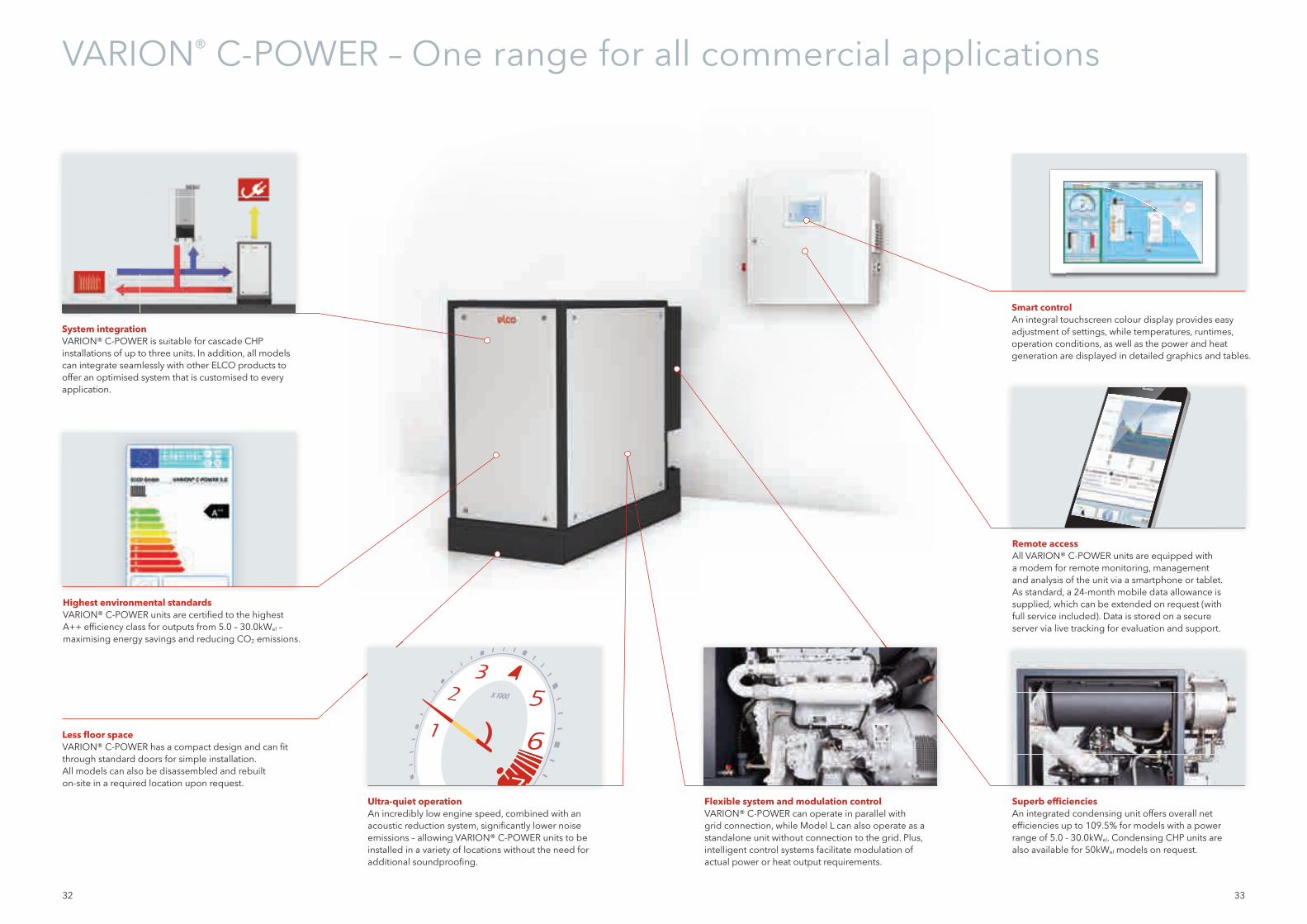
Flexible system and modulation controlVARION® C-POWER can operate in parallel with grid connection, while Model L can also operate as a standalone unit without connection to the grid. Plus, intelligent control systems facilitate modulation of actual power or heat output requirements.
System integrationVARION® C-POWER is suitable for cascade CHP installations of up to three units. In addition, all models can integrate seamlessly with other ELCO products to offer an optimised system that is customised to every application.
Remote accessAll VARION® C-POWER units are equipped with a modem for remote monitoring, management and analysis of the unit via a smartphone or tablet. As standard, a 24-month mobile data allowance is supplied, which can be extended on request (with full service included). Data is stored on a secure server via live tracking for evaluation and support.
Superb effi ciencies An integrated condensing unit offers overall net effi ciencies up to 109.5% for models with a power range of 5.0 - 30.0kWel. Condensing CHP units are also available for 50kWel models on request.
Ultra-quiet operation An incredibly low engine speed, combined with an acoustic reduction system, signifi cantly lower noise emissions – allowing VARION® C-POWER units to be installed in a variety of locations without the need for additional soundproofi ng.
Less fl oor space VARION® C-POWER has a compact design and can fi t through standard doors for simple installation. All models can also be disassembled and rebuilt on-site in a required location upon request.
Smart controlAn integral touchscreen colour display provides easy adjustment of settings, while temperatures, runtimes, operation conditions, as well as the power and heat generation are displayed in detailed graphics and tables.
Highest environmental standardsVARION® C-POWER units are certifi ed to the highest A++ effi ciency class for outputs from 5.0 – 30.0kWel – maximising energy savings and reducing CO2 emissions.
34 35
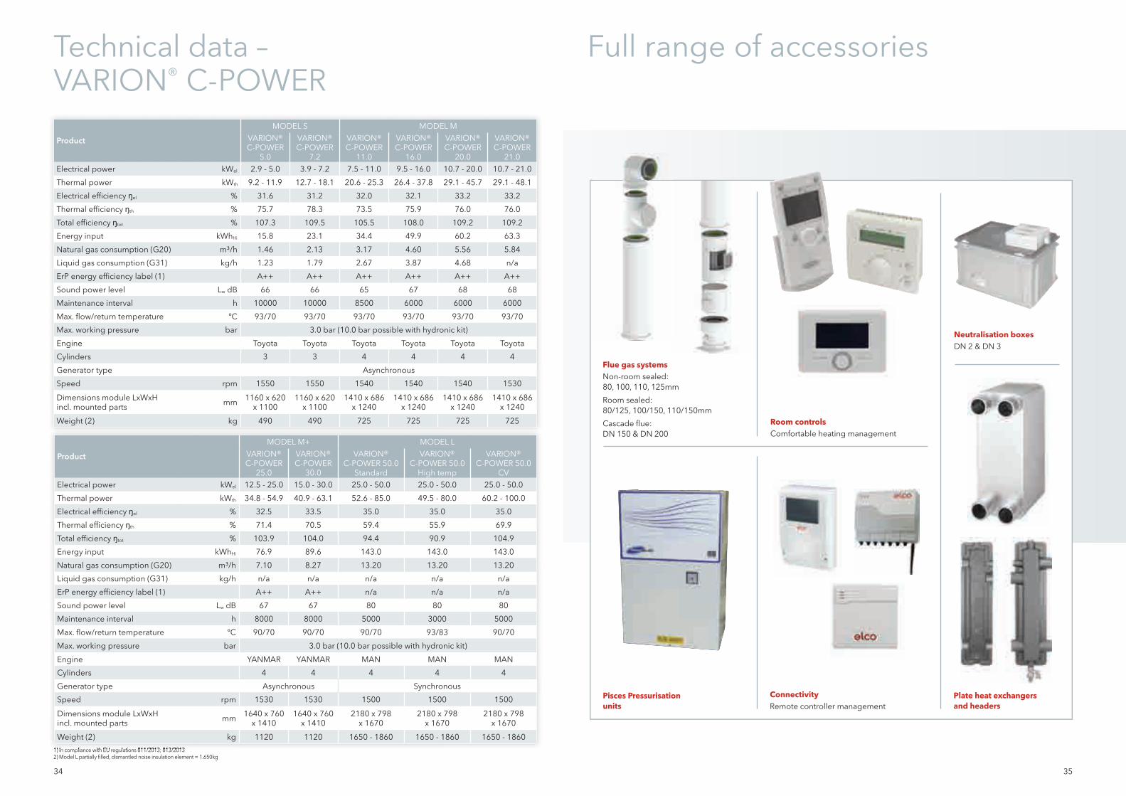
Technical data – VARION® C-POWER
Full range of accessories
Flue gas systemsNon-room sealed:80, 100, 110, 125mm
Room sealed:80/125, 100/150, 110/150mm
Cascade fl ue:DN 150 & DN 200
Neutralisation boxesDN 2 & DN 3
Room controlsComfortable heating management
ConnectivityRemote controller management
Plate heat exchangers and headers
Pisces Pressurisation units
Product
MODEL S MODEL MVARION® C-POWER
5.0
VARION® C-POWER
7.2
VARION® C-POWER
11.0
VARION® C-POWER
16.0
VARION® C-POWER
20.0
VARION® C-POWER
21.0Electrical power kWel 2.9 - 5.0 3.9 - 7.2 7.5 - 11.0 9.5 - 16.0 10.7 - 20.0 10.7 - 21.0
Thermal power kWth 9.2 - 11.9 12.7 - 18.1 20.6 - 25.3 26.4 - 37.8 29.1 - 45.7 29.1 - 48.1
Electrical efficiency ŋel % 31.6 31.2 32.0 32.1 33.2 33.2
Thermal efficiency ŋth % 75.7 78.3 73.5 75.9 76.0 76.0
Total efficiency ŋtot % 107.3 109.5 105.5 108.0 109.2 109.2
Energy input kWhHi 15.8 23.1 34.4 49.9 60.2 63.3
Natural gas consumption (G20) m³/h 1.46 2.13 3.17 4.60 5.56 5.84
Liquid gas consumption (G31) kg/h 1.23 1.79 2.67 3.87 4.68 n/a
ErP energy efficiency label (1) A++ A++ A++ A++ A++ A++
Sound power level Lw dB 66 66 65 67 68 68
Maintenance interval h 10000 10000 8500 6000 6000 6000
Max. flow/return temperature ºC 93/70 93/70 93/70 93/70 93/70 93/70
Max. working pressure bar 3.0 bar (10.0 bar possible with hydronic kit)
Engine Toyota Toyota Toyota Toyota Toyota Toyota
Cylinders 3 3 4 4 4 4
Generator type Asynchronous
Speed rpm 1550 1550 1540 1540 1540 1530
Dimensions module LxWxHincl. mounted parts mm 1160 x 620
x 11001160 x 620
x 11001410 x 686
x 12401410 x 686
x 12401410 x 686
x 12401410 x 686
x 1240
Weight (2) kg 490 490 725 725 725 725
1) In compliance with EU regulations 811/2013; 813/20132) Model L partially fi lled, dismantled noise insulation element = 1.650kg1) In compliance with EU regulations 811/2013; 813/2013
Product
MODEL M+ MODEL LVARION® C-POWER
25.0
VARION® C-POWER
30.0
VARION® C-POWER 50.0
Standard
VARION® C-POWER 50.0
High temp
VARION® C-POWER 50.0
CVElectrical power kWel 12.5 - 25.0 15.0 - 30.0 25.0 - 50.0 25.0 - 50.0 25.0 - 50.0
Thermal power kWth 34.8 - 54.9 40.9 - 63.1 52.6 - 85.0 49.5 - 80.0 60.2 - 100.0
Electrical efficiency ŋel % 32.5 33.5 35.0 35.0 35.0
Thermal efficiency ŋth % 71.4 70.5 59.4 55.9 69.9
Total efficiency ŋtot % 103.9 104.0 94.4 90.9 104.9
Energy input kWhHi 76.9 89.6 143.0 143.0 143.0
Natural gas consumption (G20) m³/h 7.10 8.27 13.20 13.20 13.20
Liquid gas consumption (G31) kg/h n/a n/a n/a n/a n/a
ErP energy efficiency label (1) A++ A++ n/a n/a n/a
Sound power level Lw dB 67 67 80 80 80
Maintenance interval h 8000 8000 5000 3000 5000
Max. flow/return temperature ºC 90/70 90/70 90/70 93/83 90/70
Max. working pressure bar 3.0 bar (10.0 bar possible with hydronic kit)
Engine YANMAR YANMAR MAN MAN MAN
Cylinders 4 4 4 4 4
Generator type Asynchronous Synchronous
Speed rpm 1530 1530 1500 1500 1500
Dimensions module LxWxHincl. mounted parts mm 1640 x 760
x 14101640 x 760
x 14102180 x 798
x 16702180 x 798
x 16702180 x 798
x 1670
Weight (2) kg 1120 1120 1650 - 1860 1650 - 1860 1650 - 1860
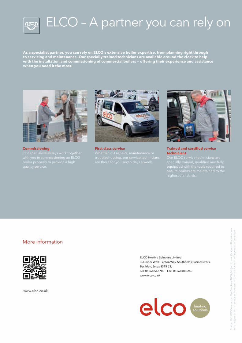
As a specialist partner, you can rely on ELCO‘s extensive boiler expertise, from planning right through to servicing and maintenance. Our specially trained technicians are available around the clock to help with the installation and commissioning of commercial boilers — offering their experience and assistance when you need it the most.
CommissioningOur specialists always work together with you in commissioning an ELCO boiler properly to provide a high quality service.
First class serviceWhether it is repairs, maintenance or troubleshooting, our service technicians are there for you seven days a week.
Trained and certified service techniciansOur ELCO service technicians are specially trained, qualified and fully equipped with the tools required to ensure boilers are maintained to the highest standards.
More information
www.elco.co.uk
Stat
us:
12
/15/
PP C
om
mer
cial
Gas
Bro
chur
e 10
/17
Sub
ject
to m
od
ifi ca
tio
ns. T
he
use
of a
ny
text
, im
ages
an
d/o
r dra
win
gs
wit
ho
ut w
ritt
en p
erm
issi
on
is a
n in
frin
gem
ent o
f co
pyr
igh
t.
ELCO – A partner you can rely on
ELCO Heating Solutions Limited
3 Juniper West, Fenton Way, Southfi elds Business Park,
Basildon, Essex SS15 6SJ
Tel: 01268 546700 Fax: 01268 888250
www.elco.co.uk


