INTELLIZONE COMMERCIAL OZONE GENERATOR Models CD-250F, CD-400F, CD-800F and CD-1200F INSTALLATION AND USER'S GUIDE IMPORTANT SAFETY INSTRUCTIONS READ AND FOLLOW ALL INSTRUCTIONS SAVE THESE INSTRUCTIONS ™ INTELLIZONE COMMERCIALOZONESYSTEM ADVANCEDSANITATIONSOLUTIONS
Transcript
1
INTELLIZONE™ COMMERCIAL OZONE GENERATOR Installation and User's Guide
INTELLIZONECOMMERCIAL OZONE GENERATORModels CD-250F, CD-400F, CD-800F and CD-1200F
INSTALLATION AND USER'S GUIDE
IMPORTANT SAFETY INSTRUCTIONSREAD AND FOLLOW ALL INSTRUCTIONS
Ozone Generator Check .........................................................................................................................................7Support Systems Check ..........................................................................................................................................7Initial Start-Up ............................................................................................................................................................7Supply Voltage Check ..............................................................................................................................................8Vacuum Regulator Check .......................................................................................................................................8External Control Check ...........................................................................................................................................8Ready for Normal Operation .................................................................................................................................8
System Overview ......................................................................................................................................................8System Power Up ...................................................................................................................................................11System States ..........................................................................................................................................................11
SECTION 5. Maintenance & Service ...............................................................................................13
Preventative Maintenance Schedule ..............................................................................................................13Electrode and Ground Tube Cleaning – Module in Place .......................................................................13Ozone and Module Inspection and Service .................................................................................................14Air Filter Cleaning ..................................................................................................................................................16Oxygen Filter Cleaning ........................................................................................................................................17Replacement Parts and Order Information ..................................................................................................18Standard Replacement Parts List .....................................................................................................................18
3
INTELLIZONE™ COMMERCIAL OZONE GENERATOR Installation and User's Guide
INTELLIZONE™ COMMERCIAL OZONE GENERATOR Installation and User's Guide
IMPORTANT SAFETY INSTRUCTIONSREAD AND FOLLOW ALL INSTRUCTIONS
Read this manual completely before attempting installation, operation or servicing.
Follow all applicable electrical codes.
A ground terminal marked is located inside the Control Enclosure near the Main Disconnect. To reduce the risk of electric shock, this terminal must be connected to the grounding means provided in the electrical supply service panel with a continuous copper wire equivalent in size to the circuit conductors supplying this equipment. For Autotransformer equipped models (-98 option), the Control Enclosure Ground Terminal is prewired to the Autotransformer. Make ground connection on the designated Terminal Block inside the Autotransformer.
Electric shock hazard. Be sure to turn power OFF before servicing. Failure to do so could result in serious injury or death.
Hazardous voltages may still be present inside cabinet when main disconnect switch is off.
Do not operate with any panels or covers removed.
Hazardous levels of ozone may be trapped in the system after a fault condition or when power is turned off during operation. Always ensure ozone has been purged by allowing Ozone Generator to complete its shutdown sequence before servicing.
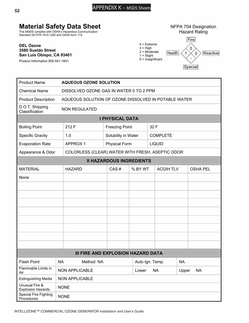
Short term inhalation of high concentrations of ozone and long term inhalation of low concentrations of ozone can cause serious harmful physiological effects. DO NOT inhale ozone gas produced by this device. Review MSDS sheets for Gaseous and Aqueous Ozone in Appendix K.
• A spontaneous and violent ignition may occur if oil, grease or greasy substances come in contact with oxygen under pressure. These substances must be kept away from oxygen regulators, cylinder valves tubing and connections, and all other oxygen equipment.
Do not store or use gasoline, chemicals or other flammable liquids or vapors near this or any other appli-ance.
SAVE THESE INSTRUCTIONS
CAUTIONS AND GENERAL NOTESThis manual covers all IntelliZone™ Commercial Ozone Generator: Models CD-250F (521644), CD-250-98 (521765), CD-400F (521667), CD-400F-98 (521767), CD-800F (521670), CD-800F - Heavy Duty (521673), CD-800F-98 (521768), CD-1200F (521676), CD-1200F - Heavy Duty (521679) and CD-1200F-98 (521769). Any variations in system operation or configuration between models are noted in the text.
1
INTELLIZONE™ COMMERCIAL OZONE GENERATOR Installation and User's Guide
SECTION 1. General Information_
Ozone ApplicationThe IntelliZone™ Commercial Ozone Generator described in this manual utilize high voltage corona dis-charge technology to generate ozone gas in high concentrations. It is designed to operate under vacuum, typically using suction provided by a venturi injector in a side stream of the process flow. Follow the instructions in this manual carefully to ensure safe and reliable operation of the Ozone Generator.
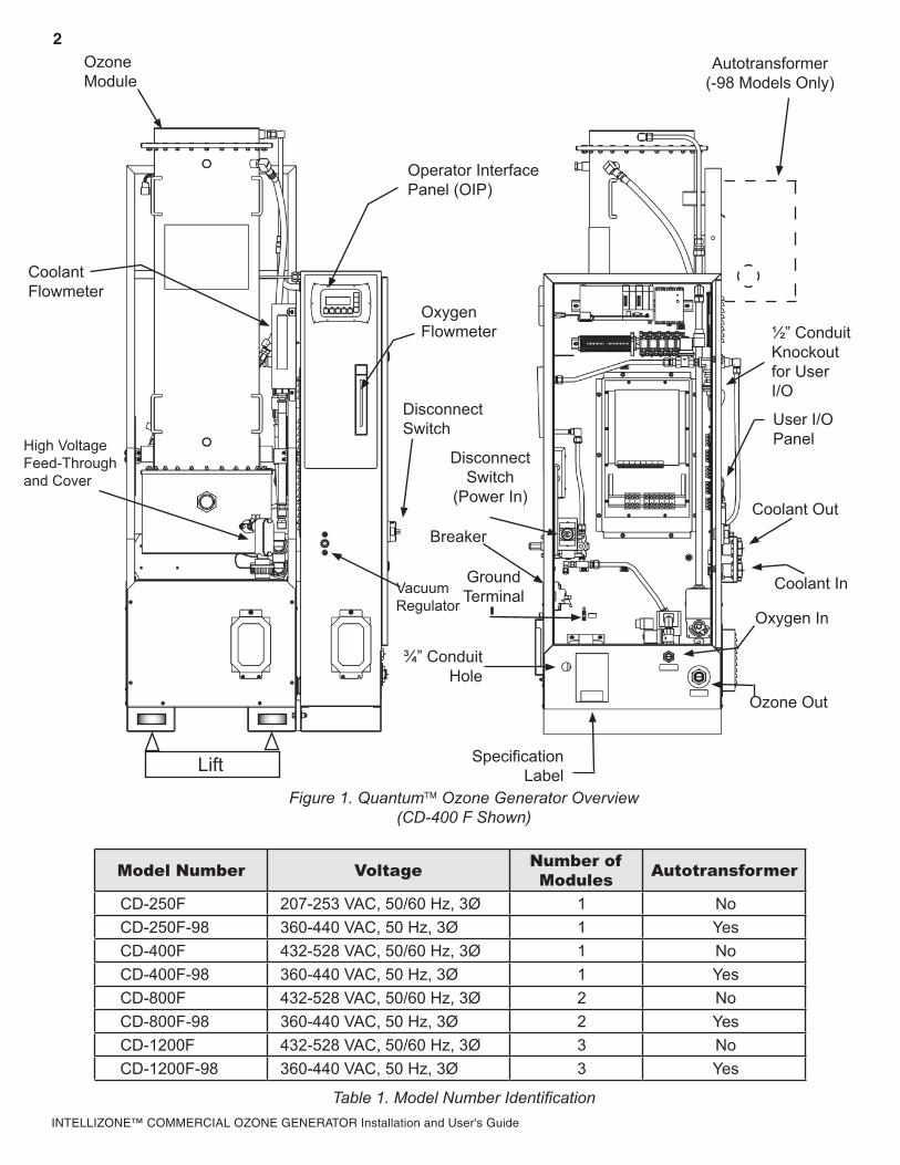
Ozone Generator OverviewRefer to Figure 1 for an overview of the ozone generator and system connections. Labels are provided on the Ozone Generator near selected connections to assist in proper installation.
a. Connectionsi. Oxygen In- ½” Female NPT Brass for oxygen supply line.ii. Ozone Out- ¾” Female NPT Stainless Steel for ozone output line.iii. Coolant In/Coolant Out- ¾” Female NPT PVC for coolant lines in and out of the Ozone Gen-
erator (labeled “Water In” and “Water Out”.)iv. Electrical- Power and Ground Connections are made inside the Control Enclosure. A hole
is provided next to Specification Label for a ¾” conduit fitting. For Autotransformer equipped models (-98 option), all electrical connections are made at the Autotransformer. Refer to Instruc-tion Sheet 4-0902-01 in Appendix J.
v. User I/O Panel- Provides terminal blocks for all user control signal connections. A ½” conduit fitting knockout is provided above the panel for control signal wires.
b. Operator Interfacei. Operator Interface Panel (OIP) - The OIP consists of a four line LCD Display to report status,
and Function Keys to allow control of Ozone Generator functions. See Section 4 for a complete description of Ozone Generator functionality and control.
ii. Oxygen Flowmeter - Displays the gas flow into the Ozone Generator. Refer to Table 1 for appropriate flow range. (Use Suction Control Valve or Injector By-pass Valve to control flow as described in Section 3.)
iii. Coolant Flowmeter - Displays the coolant flow through the Ozone Generator in gallons per minute (GPM). Make fine adjustments to the cooling water flow by adjusting the ball valve mounted on the Ozone Generator. Recommended flow rates for each model are shown on the Specification Drawings within Appendix B.
iv. Vacuum Regulator - The Vacuum Regulator is factory set to provide optimal control over a wide vacuum range and does not require adjustment. Do not adjust unless directed to do so by Technical Support. Call (800) 831-7133 for more information.
v. Disconnect Switch - The Disconnect Switch toggles power to the Ozone Generator. When turned to the ON position, the OIP will initiate and system Fans will start up. For user safety, the Control Enclosure door will not open until the Disconnect Switch is turned to the OFF position.
Warranty Summaryi. Two (2) years on entire ozone generator (see page 24).ii. Three (3) years on High Voltage Electrodes (see page 24).iii. To prevent voiding warranty, follow all installation instructions and first call (800) 831-7133 before an
authorized technician has commissioned the unit prior to first start-up. After commissioning, the end user is responsible for all routine maintenance outlined in Section 5 of this manual.
iv. For complete Warranty details see Section 7 of this manual.v. Extended Warranty and Service Agreements are available. Please contact (800) 831-7133 for more
information.
Important – The Disconnect Switch may also be used as an emergency stop switch.
2
INTELLIZONE™ COMMERCIAL OZONE GENERATOR Installation and User's Guide
Figure 1. Quantum Ozone Generator Overview(CD-400 F Shown)
Model Number Voltage Number of Modules Autotransformer
INTELLIZONE™ COMMERCIAL OZONE GENERATOR Installation and User's Guide
SECTION 2. Installation_
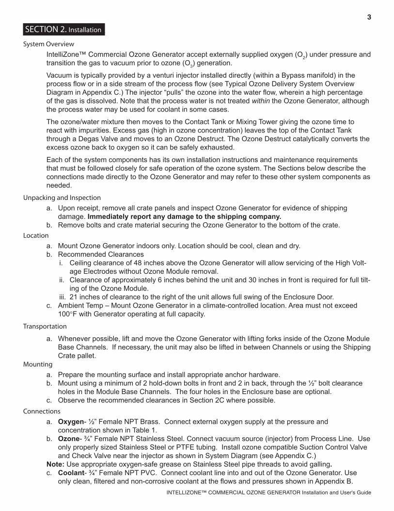
System OverviewIntelliZone™ Commercial Ozone Generator accept externally supplied oxygen (O2) under pressure and transition the gas to vacuum prior to ozone (O3) generation.
Vacuum is typically provided by a venturi injector installed directly (within a Bypass manifold) in the process flow or in a side stream of the process flow (see Typical Ozone Delivery System Overview Diagram in Appendix C.) The injector “pulls” the ozone into the water flow, wherein a high percentage of the gas is dissolved. Note that the process water is not treated within the Ozone Generator, although the process water may be used for coolant in some cases.
The ozone/water mixture then moves to the Contact Tank or Mixing Tower giving the ozone time to react with impurities. Excess gas (high in ozone concentration) leaves the top of the Contact Tank through a Degas Valve and moves to an Ozone Destruct. The Ozone Destruct catalytically converts the excess ozone back to oxygen so it can be safely exhausted.
Each of the system components has its own installation instructions and maintenance requirements that must be followed closely for safe operation of the ozone system. The Sections below describe the connections made directly to the Ozone Generator and may refer to these other system components as needed.
Unpacking and Inspectiona. Upon receipt, remove all crate panels and inspect Ozone Generator for evidence of shipping
damage. Immediately report any damage to the shipping company.b. Remove bolts and crate material securing the Ozone Generator to the bottom of the crate.
Locationa. Mount Ozone Generator indoors only. Location should be cool, clean and dry.b. Recommended Clearances
i. Ceiling clearance of 48 inches above the Ozone Generator will allow servicing of the High Volt-age Electrodes without Ozone Module removal.
ii. Clearance of approximately 6 inches behind the unit and 30 inches in front is required for full tilt-ing of the Ozone Module.
iii. 21 inches of clearance to the right of the unit allows full swing of the Enclosure Door.c. Ambient Temp – Mount Ozone Generator in a climate-controlled location. Area must not exceed
100°F with Generator operating at full capacity.
Transportation
a. Whenever possible, lift and move the Ozone Generator with lifting forks inside of the Ozone Module Base Channels. If necessary, the unit may also be lifted in between Channels or using the Shipping Crate pallet.
Mountinga. Prepare the mounting surface and install appropriate anchor hardware. b. Mount using a minimum of 2 hold-down bolts in front and 2 in back, through the ½” bolt clearance
holes in the Module Base Channels. The four holes in the Enclosure base are optional.c. Observe the recommended clearances in Section 2C where possible.
Connectionsa. Oxygen- ½” Female NPT Brass. Connect external oxygen supply at the pressure and
concentration shown in Table 1.b. Ozone- ¾” Female NPT Stainless Steel. Connect vacuum source (injector) from Process Line. Use
only properly sized Stainless Steel or PTFE tubing. Install ozone compatible Suction Control Valve and Check Valve near the injector as shown in System Diagram (see Appendix C.)
Note: Use appropriate oxygen-safe grease on Stainless Steel pipe threads to avoid galling.c. Coolant- ¾” Female NPT PVC. Connect coolant line into and out of the Ozone Generator. Use
only clean, filtered and non-corrosive coolant at the flows and pressures shown in Appendix B.
4
INTELLIZONE™ COMMERCIAL OZONE GENERATOR Installation and User's Guide
CAUTION – Potentially lethal voltages. All electrical connections must be made by a licensed electrician. Follow all applicable local and national electrical codes.
d. Electrical
i. For units without Autotransformers, connect power conductors directly to the bottom terminals of the Disconnect Switch inside the Control Enclosure. Connect earth ground conductor to the
Ground Terminal (identified by the symbol.) Run wires through appropriate ¾” conduit fit-ting installed in the hole next to the Specification Label.
ii. For Autotransformer equipped models (-98 option), all electrical connections including ground are made at the Autotransformer. Do not modify wiring within the Control Enclosure. Refer to the Instruction sheet 4-0902-01 for further details.
User I/O Panel See Figure 2 for an overview of the User I/O Panel. The User I/O Panel is located on the back wall inside the Control Enclosure. Signal wires may be run through the ½” conduit fitting knockout provided just above the Panel. Note: Remove existing jumpers as needed to install Control Signals. Jumpers must be left in place for unused Relay Input signals.a. Relay Inputs The first six inputs (starting from the top) are Relay Input connections. All connections should be
made so that a closed contact indicates normal operation (open contact indicates fault condi-tion.) For example, use the Normally Open contacts from a Flow Switch so that sufficient water flow closes the switch.Relay Input signals will affect Ozone Generator operation differently depending on the type of Input and the current State of the Ozone Generator. See Section 4 for a complete description of States and Ozone Generator Operation.
External (customer supplied) relays and/or switches must meet the following minimum ratings:
EXTERNAL RELAY MINIMUM RATINGSVOLTAGE CURRENT
24 VDC 100 mATable 2. Electrical Ratings of Relay Inputs
i. ORP – If applicable, connect the signal from an ORP Controller to cycle ozone production on and off based on process demand. If a second ORP input is required, the Stand-By or Stop Inputs may be used depending on the system requirements.
ii. Dissolved Ozone – If applicable, connect the signal from a Dissolved Ozone Controller to cycle ozone production on and off based on process demand.
iii. Remote Stand-By – Connect a switch or relay signal to place the Ozone Generator in Stand-By mode from a remote location. Ozone Generator will not start until Remote Stand-By switch is closed.
iv. Remote Stop – Connect a switch or relay signal to stop the Ozone Generator from a remote location. Ozone Generator will not restart until Remote Stop switch is closed and the Fault is cleared at the Operator Interface Panel.
5
INTELLIZONE™ COMMERCIAL OZONE GENERATOR Installation and User's Guide
ORP
DissolvedOzone
RemoteStand-By
Remote Stop
Ambient Ozone
Process Flow Switch (or Pump Interlock)
Ozone Power IndicatorOzone Fault Indicator
4-20mA Control
Customer External Connections
Enclosure Internal Connections
a) Relay Inputs+24 VDC
PLC Input
External Switch
b) Relay Outputs
External Power Supply
Internal Relay
External Indicator
c) 4-20mA Input
4-20mA Transmitter
Fuse
Optional Resistor
4-20mA Receiver
Figure 2. User I/O Panel
6
INTELLIZONE™ COMMERCIAL OZONE GENERATOR Installation and User's Guide
User I/O Panel, Cont.
v. Ambient Ozone – Connect signal from Ambient Ozone Monitor to immediately stop ozone production in the event of an ozone leak.
vi. Process Flow Switch – Install a Water Flow Switch in the Process Line near the ozone Injector. Install and calibrate the switch so that the switch closes only when sufficient water is flowing to generate appropriate vacuum at the Ozone Generator. This will provide optimum protection against water back-flow to the Ozone Generator, as well as fault-avoidance due to vacuum loss during filter backwash.
b. Relay OutputsTwo Relay Outputs are provided to communicate the status of the Ozone Generator. These signals may be run to a remote status display, for example, or connected to local signal lights. External power is required and must meet the following ratings:
RELAY OUTPUT RATINGSAC DC
MAX RESISTIVE LOAD (p.f. = 1.0) 10 A at 110 VAC 10 A at 24 VDCMAX INDUCTIVE LOAD (p.f. = 0.4) 7.5 A at 110 VAC 5 A at 24 VDCMAX OPERATING VOLTAGE 250 VAC 125 VDCMINIMUM REQUIRED LOAD --- 100 mA at 5 VDC
Table 3. Electrical Ratings of Relay Outputs
i. Ozone Power Indicator – A closed Output Relay indicates ozone production is on.
ii. Ozone Fault Indicator – An open Output Relay indicates that the Ozone Generator has encountered a Fault condition as described in Section 6 (or has been powered off). Ozone production will cease and user intervention is required.
c. 4-20mAi. A standard 2-wire 4-20 mA input is provided for optional external control of ozone output.
Enable the external control function through the Operator Interface Panel (see Section 4A) 4-20mA Input:
SPECIFICATION VALUEINPUT IMPEDANCE 125 ΩMAX CURRENT 30 mAFUSE RATING FAST-ACTING 31 mA
Table 4.1 Electrical Ratings for 4-20 mA External Control Signal
1. Connect the 2 wire 4-20 mA signal to the 4-20 mA input + and – terminals on User I/O Panel.
2. Use shortest wire route possible.
3. Use shielded wire.
4. Ground the shield at the transmitter source only.
5. Do not ground the shield at the terminal block input.
6. Avoid noise problems by routing cable away from noise sources such as motors, high current switches, transformers and AC wires.
WARNING! – For user safety and Ozone Generator protection, Ambient Ozone and Process Flow Switch connections are required. Do not operate Ozone Generator with over-ride jumpers in these locations.
7
INTELLIZONE™ COMMERCIAL OZONE GENERATOR Installation and User's Guide
7. The input signal must not exceed a maximum of 30 mA. Install an optional series resistor as needed to match the 4-20 mA transmitter output voltage and impedance to the input imped-ance.
8. The 4-20 mA signal is interpreted as follows:
CURRENT (mA) RESULT< 4 SIGNAL LOSS4 - 20 0-100% OZONE POWER21 - 30 100 % OZONE POWER> 30 MAXIMUM INPUT RATING EXCEEDED
Table 4.2 Signal for 4-20 mA External Control Signal
Pre-Commissioning ChecklistUpon completing all of the generator system connections outlined in Section 2, complete the PRE-COMMISSIONING CHECKLIST in Appendix B and SEND TO DEL OZONE by fax at 805-541-5452 or e-mail to [email protected]. Once form has been sent, contact DEL Ozone 805-541-1601 to schedule commissioning.
SECTION 3. Commissioning_
Perform commissioning prior to initial start up of Ozone Generator and upon re-starting after service.Note: If necessary, use the Disconnect Switch to shut down power at any point during Commissioning.
Ozone Generator Check.a. Review Pre-Commissioning Checklist (Appendix B) and correct any non-conformities.b. Verify that Ozone Generator is mounted in an appropriate (cool, clean, indoor) location.
Support Systems Checka. Start-up Oxygen Preparation system and verify that proper pressure (30psi) is available at the
Ozone Generator.b. Start-up Cooling system and/or open appropriate cooling line valves.c. Start Process circulation system and adjust injector bypass to pull a strong vacuum. The injector
should cavitate causing a rattling sound. This is normal.d. Verify proper supply voltage at the Ozone Generator.
Initial Start-Upa. With the Enclosure Door open, override the disconnect switch by turning the shaft extending from
the switch. b. Turn on breaker.
c. PLC will automatically run through its start up and begin sequentially verifying sensor inputs in order to proceed.
d. If applicable, Flow and Vacuum fault messages will appear on the OIP Display. Use Injector Bypass and Suction Control Valve to balance gas flow, DO NOT ADJUST VACUUM REGULATOR. See Section 4 (Operation) or Section 6 (Troubleshooting) for further instructions. Once gas system is adjusted properly, the Ozone Generator will progress to the STOPPED State.
NOTE – Initial commissioning to be performed by Authorized DEL technicial ONLY.
DANGER! LETHAL VOLTAGES PRESENT. KEEP UNAUTHORIZED PERSONNEL AWAY FROM ENCLOSURE WHEN DISCONNECT SWITCH IS OVER-RIDDEN.
8
INTELLIZONE™ COMMERCIAL OZONE GENERATOR Installation and User's Guide
e. Press F1 to start Ozone Generator. If gas flow is balanced, coolant flow is sufficient and external contacts (ORP, Dissolved Ozone, etc) are closed, the generator will start.
f. Verify that Ozone Generator Power Level is set to 100% as indicated on the OIP Display.g. For multiple Module models, verify proper balance of Oxygen and Coolant flow between Modules.
Since balance is pre-set at the factory, only slight adjustments should be necessary. h. Check for water leaks in coolant plumbing. Shut down Ozone Generator and fix leaks as required.
Supply Voltage Checka. Allow Ozone Generator to warm up for several minutes and re-check supply voltage. If supply volt-
age is not within specifications, shut down and notify facility manager.b. If supply voltage is within specifications, press F2 to stop. Wait for the Ozone Generator to complete
it’s SHUTTING DOWN sequence.c. Carefully turn Disconnect Switch back to OFF position.d. Close and latch Enclosure Door.
Vacuum Regulator Checka. Turn Disconnect Switch back to ON position.b. Bring Ozone Generator back to READY State. Ensure that “Oxygen Save Mode” and “Auto Mode”
are OFF to allow gas flow (see Section 4.) c. Use the Suction Control Valve to choke off vacuum to the Ozone Generator. Verify that the Ozone
Generator continues to run when flow drops to approximately 50cfh per module.External Control Check
a. From READY State, re-enable Auto Mode (press F3) and press F1 to start ozone production. Verify that ORP/Dissolved ozone level rises. Wait for level to reach set point (or bring set point down) to verify that ozone turns off.
b. Check other external controls as required.Ozone Generator is now ready for normal operation. Review Section 4 for details on control system operation and user
settings. After start up, the control system will automatically cycle the generator on and off as needed to maintain required ozone level. Initial system start up procedures need to be followed again in the event of a safety interlock system shut down or an interruption in the main power.
SECTION 4. Operation_
For first time startup: Perform Commissioning as outlined in Section 3.System Overview
The Ozone Generator is controlled by a programmable logic controller (PLC). An LCD screen provides user feedback on the status of the Ozone Generator and a keypad allows input of user settings and control of the Ozone Generator. a. Operator Interface Panel (OIP)
i. The Operator Interface Panel on the front of the Controls Enclosure consists of a four line LCD display to report essential user information and a keypad to allow control of Ozone Generator functions.
ii. The OIP has two screen modes: “PLC Message” and “Diagnostics and Settings”. Functions and Display information will change with each mode as noted below.
Note: The PLC Message Screen has priority over the Diagnostics and Settings Screen. When an Ozone Generator State change occurs, the display will automatically switch to the PLC Message screen. Press ESC to return to the Diagnostics and Settings Screen.
b. PLC Message Screen - In this mode, the PLC will update the screen with current information about the Ozone Generator’s State of operation. The “PLC Message” LED is illuminated when the screen is in this mode. See Table 5 for function of Keys in this mode.
9
INTELLIZONE™ COMMERCIAL OZONE GENERATOR Installation and User's Guide
Figure 3a. Typical OIP Display in “PLC Message” Mode
KEY FUNCTION
F1 – F5 SOFT KEYS. FUNCTIONS DEFINED ON SCREEN MENU
ESC SWITCH TO DIAGNOSTICS AND SET-TINGS MENU
UP/DOWN NONEENTER NONE
Table 5. Function of OIP Keys in “PLC Message” Mode
c. Diagnostics and Settings Menu - The Diagnostics and Settings menu consists of six main folder items as shown in Figure 3b. Each folder contains user settings or diagnostic information. Use the UP/DOWN arrow keys to scroll to the desired folder and press the ENTER key to open the folder. Use the ESC key to exit a folder. Table 6 describes the key functions in this mode.
KEY FUNCTION
F1 – F5 SOFT KEYS FUNCTION AS DEFINED ON THE CURRENT (ALTHOUGH NOT VISIBLE) PLC MESSAGE SCREEN MENU
ESC EXIT MENU LEVELS OR SWITCH TO PLC MESSAGE MODE
UP/DOWN SCROLL THROUGH MENU AND CHANGE SETTINGS
ENTER ENTER FOLDERS AND EDIT SETTINGSTable 6. Function of OIP Keys in “Diagnostics and Settings” Mode
INTELLIZONE™ COMMERCIAL OZONE GENERATOR Installation and User's Guide
USER SETTINGS POWER SETTING 100 % 4-20 mA MODE 1 OXYGEN SAVE MODE 1 CURRENT SENSORS MODULE 1 22.4 Amps MODULE 2 21.9 Amps MODULE 3 22.1 Amps PRESSURE SENSORS MODULE 1 12.4 PSIA MODULE 2 12.2 PSIA MODULE 3 12.3 PSIA OTHER DIAGNOSTICS RUNTIME 1234.5 HRS OXYGEN SENSOR 96.8 % 4-20 mA INPUT 100 % PDM OUTPUT 85 % FAULT CODE HISTORY FAULT 10 AT 1234.5 FAULT 9 AT 1234.5 FAULT 8 AT 1234.5 FAULT 7 AT 1234.5 FAULT 6 AT 1234.5 FAULT 5 AT 1234.5 FAULT 4 AT 1234.5 FAULT 3 AT 1234.5 FAULT 2 AT 1234.5 FAULT 1 AT 1234.5 --------END---------FAULT CODE MEANINGS 1...............BFPD 2...........LOW O2 % 3....LOW O2 PRESSURE 4.........LOW VACUUM . . .
Figure 3b. Diagnostics and Settings Menu Tree
i. USER SETTINGS – This folder contains all available user settings. To change any of these settings: - Use the UP/DOWN arrow keys to scroll to the desired setting and press ENTER. - Use the UP/DOWN arrow keys to change the setting to the desired value. - Press ENTER to complete the change, or ESC to cancel.
1. POWER SETTING – Use Power Setting to scale ozone generation between 0 and 100%. Func-tions only when 4-20 mA mode is NOT enabled.
2. 4-20 mA MODE – This setting may either be ON (setting = 1) or OFF (setting = 0). When this mode is turned on, an external 4-20mA signal will scale ozone generation between 0 and 100%. Note: If 4-20mA mode is turned on, a fault message will appear unless an appropriate 4-20mA signal is present.
3. OXYGEN SAVE MODE – This setting may either be ON (setting = 1) or OFF (setting = 0). When this mode is on, gas flow valves will be closed during the READY state. This reduces the duty cycle of the oxygen system, but will result in a delay during restart of ozone production. If this mode is off, oxygen will continue to flow during the READY state and ozone production will begin without delay.
ii. CURRENT SENSORS – This folder contains sensor readings for the electrical current (Amps RMS) being delivered to each Ozone Module. Only installed Modules will be listed, depending on model.
11
INTELLIZONE™ COMMERCIAL OZONE GENERATOR Installation and User's Guide
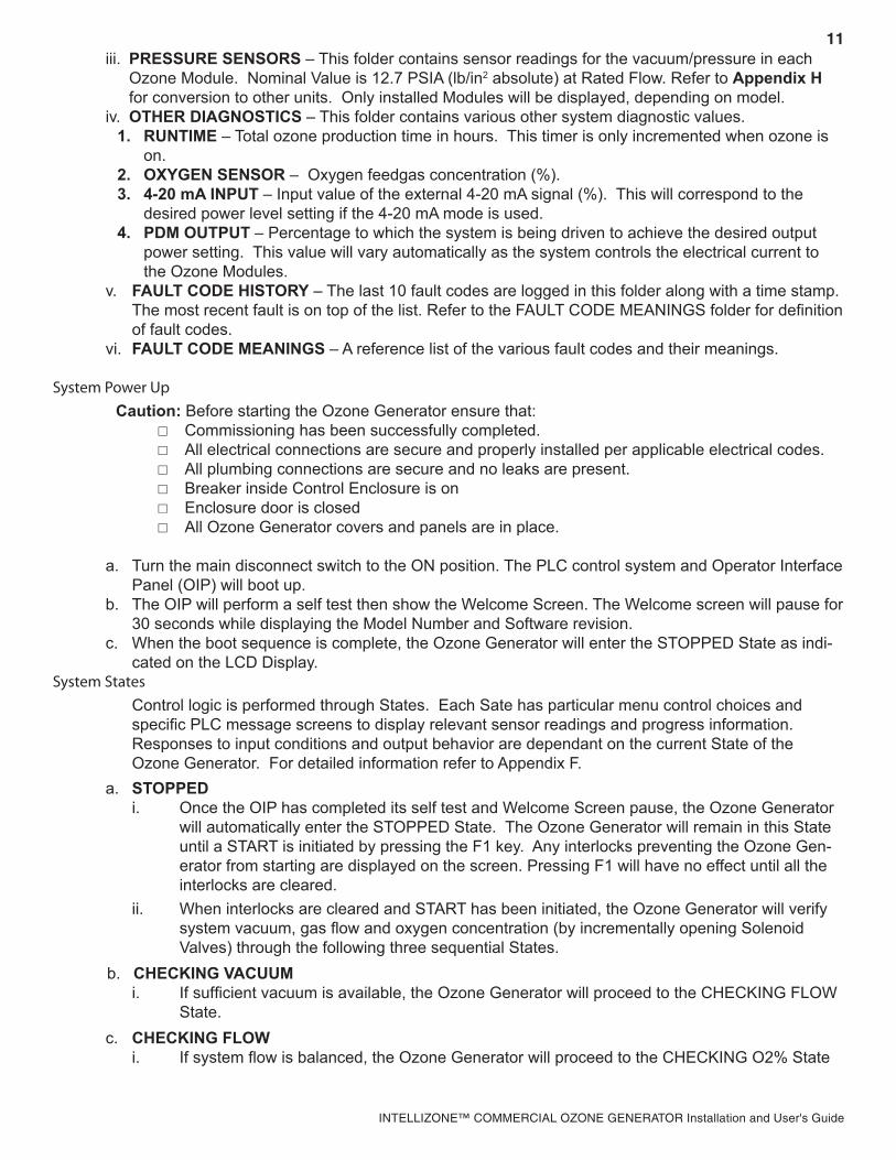
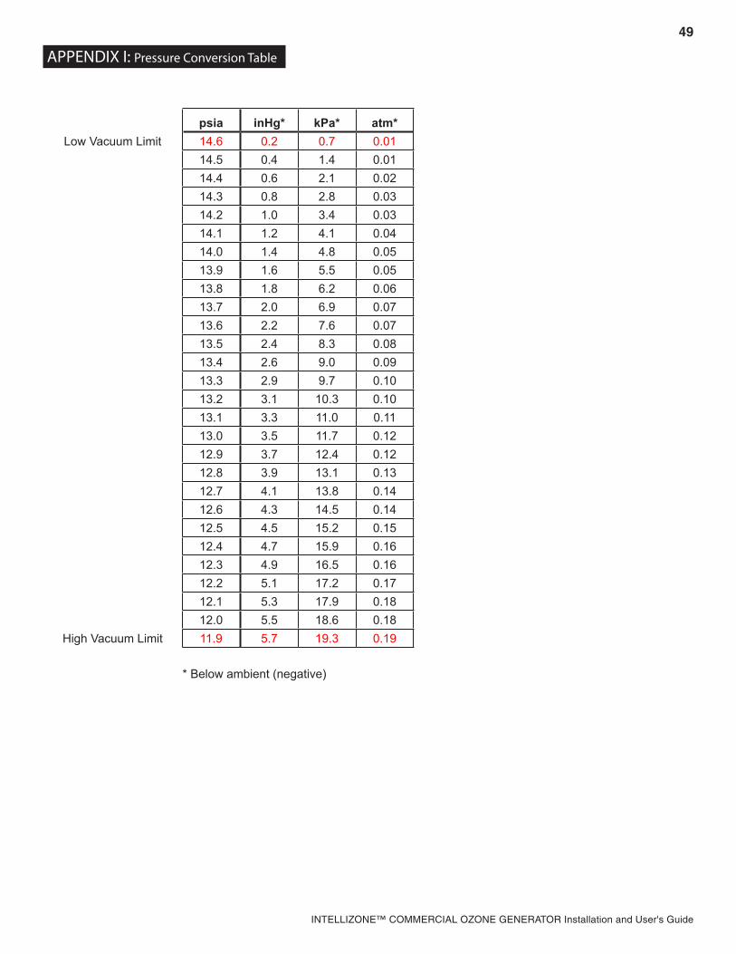
iii. PRESSURE SENSORS – This folder contains sensor readings for the vacuum/pressure in each Ozone Module. Nominal Value is 12.7 PSIA (lb/in2 absolute) at Rated Flow. Refer to Appendix H for conversion to other units. Only installed Modules will be displayed, depending on model.
iv. OTHER DIAGNOSTICS – This folder contains various other system diagnostic values.1. RUNTIME – Total ozone production time in hours. This timer is only incremented when ozone is
on.2. OXYGEN SENSOR – Oxygen feedgas concentration (%).3. 4-20 mA INPUT – Input value of the external 4-20 mA signal (%). This will correspond to the
desired power level setting if the 4-20 mA mode is used.4. PDM OUTPUT – Percentage to which the system is being driven to achieve the desired output
power setting. This value will vary automatically as the system controls the electrical current to the Ozone Modules.
v. FAULT CODE HISTORY – The last 10 fault codes are logged in this folder along with a time stamp. The most recent fault is on top of the list. Refer to the FAULT CODE MEANINGS folder for definition of fault codes.
vi. FAULT CODE MEANINGS – A reference list of the various fault codes and their meanings.
System Power UpCaution: Before starting the Ozone Generator ensure that:
Commissioning has been successfully completed. All electrical connections are secure and properly installed per applicable electrical codes. All plumbing connections are secure and no leaks are present. Breaker inside Control Enclosure is on Enclosure door is closed All Ozone Generator covers and panels are in place.
a. Turn the main disconnect switch to the ON position. The PLC control system and Operator Interface Panel (OIP) will boot up.
b. The OIP will perform a self test then show the Welcome Screen. The Welcome screen will pause for 30 seconds while displaying the Model Number and Software revision.
c. When the boot sequence is complete, the Ozone Generator will enter the STOPPED State as indi-cated on the LCD Display.
System StatesControl logic is performed through States. Each Sate has particular menu control choices and specific PLC message screens to display relevant sensor readings and progress information. Responses to input conditions and output behavior are dependant on the current State of the Ozone Generator. For detailed information refer to Appendix F.
a. STOPPEDi. Once the OIP has completed its self test and Welcome Screen pause, the Ozone Generator
will automatically enter the STOPPED State. The Ozone Generator will remain in this State until a START is initiated by pressing the F1 key. Any interlocks preventing the Ozone Gen-erator from starting are displayed on the screen. Pressing F1 will have no effect until all the interlocks are cleared.
ii. When interlocks are cleared and START has been initiated, the Ozone Generator will verify system vacuum, gas flow and oxygen concentration (by incrementally opening Solenoid Valves) through the following three sequential States.
b. CHECKING VACUUMi. If sufficient vacuum is available, the Ozone Generator will proceed to the CHECKING FLOW
State.c. CHECKING FLOW
i. If system flow is balanced, the Ozone Generator will proceed to the CHECKING O2% State
12
INTELLIZONE™ COMMERCIAL OZONE GENERATOR Installation and User's Guide
d. INSUFFICIENT VACUUM/INSUFFICIENT FLOWi. If proper flow conditions are not attained within 2 minutes, all valves will close as a precau-
tion against water backflow. One of the following messages will appear:1. INSUFFICIENT VACUUM if vacuum is too low or not present. Establish proper vacuum
to continue.2. INSUFFICIENT FLOW if system flow is unbalanced. Correct vacuum and/or oxygen
flow to continue.e. CHECKING O2 %
i. Once gas flow through the Ozone Generator is balanced, the system will pause to verify that oxygen concentration is steadily greater than 85% for 2 minutes in order to proceed.
ii. As long as no other fault occurs, the system will remain in the CHECKING O2% State until correct oxygen concentration is detected.
iii. Once the above system checks have been completed successfully, the Ozone Generator will proceed to the READY State.
f. READYi. Once gas flow and vacuum balancing has been completed, the Ozone Generator will enter
the READY State. The system will behave differently in this State depending on previously discussed settings (Section 4A):1. If “Oxygen Save Mode” is enabled, all valves will be closed and gas will not flow.2. If “Oxygen Save Mode” is disabled, valves will remain open and gas will continue to
flow.ii. Process Flow Switch – The Ozone Generator may also enter the READY State from the
RUNNING State if the Process Flow switch opens. All gas flow valves will be closed and vacuum will be locked in the Ozone Generator. When process flow returns, the generator will resume normal operation.
iii. AUTO MODE1. In the READY State, the F3 key will toggle “AUTO MODE” On/Off.2. In AUTO MODE, the Ozone Generator will automatically start or stop ozone produc-
tion as required by external control signals such as ORP, Dissolved Ozone and Remote Standby. If ORP is high, for example, the Ozone Generator will switch to the READY State (ozone off). When ORP drops it will return to the RUNNING State (ozone on).
g. STARTINGThis is a transition State from READY to RUNNING. Gas flow valves are re-opened (if applicable) and the Coolant Valve is opened. If vacuum and flow balance have been maintained and sufficient Coolant flow is detected, the Ozone Generator enters the RUNNING State.
h. RUNNINGIn this State, feed gas is flowing, coolant is flowing, and ozone is being produced. Ozone produc-tion will continue until input signal(s) indicate no demand for ozone, a fault is encountered or the user presses F2 to STOP.
i. SHUTTING DOWN In this State, Ozone is off and feed gas flows through the system to purge residual ozone from the module and gas lines. Time remaining is displayed on the LCD screen.
j. FAULT Fault conditions require the Ozone Generator to shutdown immediately to prevent potential equip-
ment damage and/or protect from a hazardous condition.The condition that caused the Fault will be displayed on the screen. Ozone, oxygen and coolant flow are all stopped.
CAUTION – When shutting the Ozone Generator down for maintenance or servicing, always allow the SHUTTING DOWN State to complete. Failure to do so may trap high concentrations of ozone gas in the system, presenting a safety hazard. When shutdown is complete the “STOPPED” message will be dis-played on the LCD screen.
13
INTELLIZONE™ COMMERCIAL OZONE GENERATOR Installation and User's Guide
The situation that caused the fault must be corrected before resuming operation. Once the source of the fault is corrected, press F4 to acknowledge and clear the Fault Screen. The Ozone Generator will then return to the STOPPED State. Refer to Troubleshooting Section 6, if necessary.
SECTION 5. Maintenance & Service_
Preventative Maintenance ScheduleNote: Refer to Figure 4 on Page 15 of this manual. A Maintenance Log Sheet is provided in Appendix G. Record all maintenance and service activity for warranty purposes.
a. Dailyi. Verify that no Fault messages are displayed on the Operator Interface Panel.ii. Check Gas Flowmeter(s) and Coolant Flowmeter(s) for proper level. For multiple Module
models, verify proper balance between Modules.iii. On the Operator Interface Panel, check Module Pressure(s) Level and Current(s) for proper
levels.b. Weekly
i. Visually inspect cabinet Air Filters for foreign objects or obstructions. Clean as needed (see Section 5D.)
ii. Visually inspect Oxygen Filter. Clean or replace filter element as required (see Section 5E.)iii. Look through Ozone Module Sight Glass to verify that all electrodes are lit and that no mois-
ture has accumulated in High Voltage Housing.iv. Check for proper operation of the Ozone Destruct Unit and Water Dump Valve.
c. Monthlyi. Perform a function test of ambient ozone monitor (if installed).
d. Three Monthsi. Verify proper operation of cooling fans.ii. Test all PLC safety interlocks.
e. Six Monthsi. Verify that High Voltage Transformer and Inductor thermal switches are glued in place. Check
that power connections are secure.ii. Check that the high voltage cable is not chafing on any surfaces.iii. Verify that High Voltage Feed-Through is secure and free of corrosion. Remove dust buildup.iv. Inspect areas near coolant plumbing for evidence of any water leaks and resulting damage or
corrosion.v. Perform general cleaning throughout the Enclosure.vi. Inspect electrical system for corroded contacts or chafed wires. Clean/repair.vii. Remove Zinc Anodes and inspect for wear. Replace as needed.
f. Twelve Monthsi. Disassemble, inspect and clean Ozone Generator Module. Refer to Section 5C for instructions.
WARNING! – Disconnect and lock out power to the Ozone Generator prior to opening doors or removing panels.
CAUTION – Ozone gas may be trapped in the Module and gas lines after a Fault. Do not disconnect gas lines until a SHUTTING DOWN sequence has been successfully completed.
14
INTELLIZONE™ COMMERCIAL OZONE GENERATOR Installation and User's Guide
Electrode and Ground Tube Cleaning – Module in Placea. If there is at least 48 inches of clearance between the top of the Ozone Module and the Ceiling, Elec-
trodes may be serviced with the Module in place. Otherwise, Module will need to be removed as described in Section 5C.
b. To service Electrodes with the Module in place, remove the ¼-20 hex bolts securing the Top Endcap of the Ozone Module.
c. Disconnect ozone output line by loosening nut on compression fitting. Move tubing out of the way.d. Remove and set aside the Endcap and Gasket. The ends of the High Voltage Electrodes are now
exposed.e. The electrodes can be removed by gripping the exposed ends firmly and carefully pulling the electrodes
out. Twisting the electrodes slightly will help with removal.f. Clean and reinstall electrodes and reattach Top Endcap using the procedure described in Section 5Cd.
Ozone Module Inspection and Service
a. Ozone Module Removali. Perform normal system shut down procedure.ii. Turn off and lock out main electrical service.iii. Remove High Voltage Feedthrough Assembly
1. Remove Cover from Conduit Fitting.2. Remove nut and washer securing Ring Lug to High Voltage Feed-Through.3. Loosen the Hose Clamp and pull the Conduit fitting free of the High Voltage Feedthrough.
(The grommet on the Top Panel may be pushed into the Transformer Enclosure if necessary.)4. Remove the Feedthrough Ring Clamp and disconnect the Feedthrough by gently pulling it
from the module. Set the Feedthrough and Sealing Ring aside to avoid damage. iv. Find the Thermal Switch at the top-rear of the Ozone Module. Disconnect the Switch at the Sealed
Connector.v. Drain Module
1. Close the Coolant Ball Valve located behind the lower left side of the Ozone Module.2. Disconnect the Coolant line entering the top of the Flowmeter at the Quick Disconnect fitting.
A small amount of coolant will spill out, catch as much as possible to limit spills on the Trans-former Enclosure.
3. Move the hose to a convenient location for draining (add extension hose as required), and reopen the Coolant Ball Valve.
4. Disconnect the Brass swivel fitting from the top of the Module. Wait for all coolant to drain from the Module.
vi. Disconnect the oxygen inlet and ozone output lines by removing the stainless steel compression nuts (located at the bottom and top of the Module, respectively.) Move tubing out of the way.
vii. Disconnect the module ground wire from the rear-lower flange of the CD Module.viii. With proper Ozone Module support in place, remove the two bolts that secure the module to the
Frame.ix. Remove Safety Cable from the left module support.
WARNING! – Ozone Module is extremely heavy. Support module with proper rigging prior to loosening bolts. Keep clear of module front while tilting.CAUTION – When shutting the Ozone Generator down for maintenance or servicing, always allow the SHUTTING DOWN State to complete. Failure to do so may trap high concentrations of ozone gas in the system, presenting a safety hazard. When shutdown is complete, the “STOPPED” message will be dis-played on the LCD.
WARNING! – The Ozone Module can now rotate on the Support Pins and may fall forward if not properly restrained.
15
INTELLIZONE™ COMMERCIAL OZONE GENERATOR Installation and User's Guide
x. Carefully move Module onto a work bench with the Sight Glass facing up for further disas-sembly.
b. Ozone Module Disassemblyi. Remove the ¼-20 hex bolts securing the Top Endcap of the Ozone Module Note: Mark
orientation of Ozone Fitting for re-assembly.ii. Remove and set aside the Endcap and Gasket. The ends of the High Voltage Electrodes are
now exposed.iii. Grip the exposed Electrode ends firmly and carefully pull the Electrodes out. Twisting the
Electrodes slightly will help with removal. Set the Electrodes aside to avoid damage.iv. Remove the ¼-20 hex nuts securing the bottom High Voltage Housing to the generator.
Carefully remove and set aside the HIgh Voltage Housing and gasket.v. The Electrodes, generator housings, and gaskets are now exposed for inspection, cleaning,
and/or replacement. See the end of this Section for Replacement parts list.c. Ozone Module Component Inspection
i. High Voltage Housing 1. Inspect High Voltage Sockets (on High Voltage Plate) for proper tightness, damage, or
corrosion. Clean, repair or replace as needed. 2. Inspect Sight Glass for cracks, replace if necessary. 3. Inspect bottom of Housing for evidence of water intrusion and excessive corrosion.
This may indicate a Water Jacket Failure or Backflow problem. Troubleshoot cause and replace parts as needed.
4. Inspect Gasket for damage. Replace as needed.ii. Top Endcap 1. Inspect Top Endcap for evidence of water intrusion and excessive corrosion. Clean/
replace as needed 2. Inspect Gasket for Damage. Replace as needed.iii. Electrodes – Inspect for deposit buildups, pitting or cracks. Replace as needed.iv. Water Jacket – Clean thoroughly then inspect all weld seams. Replace Water Jacket if nec-
essary.d. Ozone Module Re-Assembly
Note: It is imperative that all Ozone Module components be free of contaminants during re-assem-bly. Remove all surface corrosion, grease, oil, lint, dirt, etc.i. Clean Water Jacket Ground Tubes by swabbing the inside of the tubes with an alcohol-
soaked, clean, lint-free cloth (using rifle cleaner or equivalent tool.)ii. Reinstall the lower Gasket and High Voltage Housing (sight glass should be facing up.) Apply
anti-seize compound to two opposite studs. Install washers and nuts hand tight.iii. Clean Electrodes using an alcohol-soaked, clean, lint-free cloth.iv. Look into the Sight Glass using a flashlight. Insert Electrodes into Ground Tubes starting at the
bottom. Line up Electrode with corresponding socket and carefully push/twist into the socket. If an Electrode fails to line up with a socket, swap with a different electrode. If socket is dam-aged, remove Housing and replace it. Continue inserting the remaining electrodes in the same manner.
Note: Do not touch Electrode Glass during installation. Handle with a clean, dry, lint-free cloth.v. Apply anti-seize compound to remaining studs on High Voltage Housing. Install washers and
nuts and tighten in groups of three in an alternating pattern using two passes. First Pass: torque to 25in•lbs. Second pass: torque to 37+/-3 inlbs.
vi. Reinstall the Top Endcap using the same technique above (note proper orientation.)
16
INTELLIZONE™ COMMERCIAL OZONE GENERATOR Installation and User's Guide
Soft Start Fuses
Figure 4b. Overview, CD-250F only Note: NOT on CD-250F-98
Figure 4a. Generator Overview, Maintenance and Service CD-400F Shown (CD-800F and CD-1200F Typical)
Fuse for 4-20mA
Breaker & System
Fuses
VacuumRegulator
Coolant Temperature
SwitchModule Support
Bolts
Coolant Disconnect
Transformer, Inductor, Thermal Switches and Fan
(Back Cover Removed)
Transformer Enclosure
ControlEnclosureFan
OxygenFilter
CheckValve
BackflowDetector
Electrodes
Ozone Module
High VoltageFeed-through
SightGlass
High Voltage Housing
Air Filters
Top Endcap
Zinc Anode
Zinc Anode
Safety Cable
Module Ground
Wire
Coolant Ball Valve
17
INTELLIZONE™ COMMERCIAL OZONE GENERATOR Installation and User's Guide
Ozone Module Inspection and Service, Cont.e. Ozone Module Reinstallation
i. Move the Ozone Module to the Frame and rest on Support Brackets. Line up mounting brackets on the back of the Water Jacket with the Frame and rotate into place. Reinstall Module Support Bolts.
ii. Reconnect Thermal Switch connector.iii. Connect Oxygen Inlet and Ozone Outlet lines. (Use a back up wrench on the Compression fit-
ting body when tightening the Compression Nut.)iv. Carefully insert the High Voltage Feedthrough into the High Voltage Housing with Sealing Ring
first. Feedthrough will need to align with socket on High Voltage Plate. View alignment through Sight Glass if necessary and press in until secure.
v. Reattach and tighten Feedthrough Ring Clamp.vi. Place High Voltage Cover over Feedthrough. Verify that Grommet is properly installed on Top
Panel of Transformer Enclosure.vii. Reinstall High Voltage Cable ring lug on High Voltage Feed-Through using star washers and
nut.viii. Tighten hose clamp and reinstall conduit fitting cover.ix. Reconnect Coolant in and out linesNote: Coolant must enter at the bottom of the module and exit at the top.x. Reconnect ground wire to Module.
Air Filter Cleaninga. Perform normal system shutdown procedureb. Air Filters are located on lower front of Controls Enclosure and (each) Transformer Enclosure.
There are two to four filters depending on Ozone Generator model.c. Back out thumb screw on top of Filter Support Bracket.d. Filter Bracket should slide up and free of the lower nuts. If lower nuts are too tight, back them out
slightly until Bracket slides out with Filter.e. Inspect Filter and Gasket for damage. Order replacement Filter as needed (see the end of this Sec-
tion for Replacement Parts list.)f. If Filter and Gasket are in good condition, the Filter may be cleaned by rinsing with warm water and
mild detergent in opposite direction of air flow (into the gasket side.)g. Allow Filter to dry completely and reinstall.
Oxygen Filter Cleaninga. Perform normal system shutdown procedure.b. Depressurize Oxygen line.c. Filter is located inside Controls Enclosure immediately after Oxygen inlet.d. Remove Bowl by depressing red button at the top while turning the Bowl. (Red button may be out of
direct view.) Drop bowl down and pull out of Enclosure.e. Unscrew Filter Element Retainer, and remove Filter Element. O-ring should also drop out.f. Inspect Filter Element and O-ring. Filter Element can be cleaned by Tapping on a hard surface and
using compressed air to blow out residual dirt. If a new Filter or O-Ring is required, see end of this section for Replacement Parts list.
g. Wipe Bowl with soft cloth. Note: If excessive moisture is present in the Bowl, check Oxygen Prepa-ration System for proper operation.
h. If Automatic Drain in the Bowl appears dirty, disassemble and clean using compressed air.i. Reassemble Bowl, reinstall Filter Element (with O-ring first) and Reattach Bowl. Be sure that Bowl
locks into place.
18
INTELLIZONE™ COMMERCIAL OZONE GENERATOR Installation and User's Guide
Replacement Parts and Order Information
For Replacement Parts call 800.831.7133 with the following information:a. Customer Nameb. Customer Addressc. Model Numberd. DEL Serial Number
Standard Replacement Parts Lista. Cabinet Air Filter with Gasket 9-0666-01b. Control System Fuses (1Amp, type FLQ) 5-1557-01c. Soft Start Fuses (3Amp, type 3AG Slow) 5-9019d. 4-20mA External Control Fuse (31mA, type 3AG) 5-1576-01e. Check Valve, ¾” SS 8-0697f. Check Valve rebuild kit 8-0333g. Oxygen Filter Element & O-ring 7-0125h. Electrode Assembly 9-0420i. Water Jacket Gasket 7-0772j. 12kVA Transformer Assembly 9-0660k. Zinc Anodes, ½” MNPT 2-0150
19
INTELLIZONE™ COMMERCIAL OZONE GENERATOR Installation and User's Guide
SECTION 6. Troubleshooting_
Introduction: The Operator Interface Panel (OIP) will provide immediate text notification of all system faults detected by the PLC. The sections below list various system and PLC faults that may be encountered during normal operation, along with typical causes and potential corrections. Other error messages may occur on start-up that are not listed here. See Section 4 for start-up details.
The PLC also maintains a Fault History which can be accessed through the Diagnostics and Settings screen of the OIP. See Section 4 for details on Fault Messages and accessing Fault History.
System will not start
CAUSE SOLUTION
No Power Verify that main supply conductors are properly connected and that correct voltage is present.
Breaker Off Reset Breaker inside Control Enclosure. Reset any external Breakers.
Bad Fuse(s)Check Control Circuit Fuses (2 ea) inside the Control Enclosure. For CD-250F models, also check Soft Start Fuses (3 ea). Replace as needed (see Replacement parts list at the end of Section 5.)
Low Ozone Output
CAUSE SOLUTIONOzone Power Setting too low Turn up Power as described in Section 4.
Bad ElectrodesWith Ozone Generator running, use a flashlight to look through the Ozone Module Sight Glass. Note any Electrodes that are not glowing and service as described in Section 5.
Warm Coolant Lower coolant temperatures and higher coolant flow rates will yield higher ozone output. Nominal coolant inlet temperature is 60°F. However, temperature can be as low as 50°F to further increase Ozone Output.Low Coolant Flow Rate
Module Current does not correspond to Power Setting
CAUSE SOLUTION
Bad ElectrodesWith Ozone Generator running, use a flashlight to look through the Ozone Module Sight Glass. Note any Electrodes that are not glowing and service as described in Section 5.
Fault Message: BFPD
CAUSE SOLUTION
Water Back Flow Detected
1. Identify and correct source of water backflow.2. Clean or replace any faulty check valves.3. Remove, clean and thoroughly dry all gas plumbing exposed to water backflow.
WARNING! – Shut down system and lock out power before opening Enclosure Door or removing Panels.
20
INTELLIZONE™ COMMERCIAL OZONE GENERATOR Installation and User's Guide
Fault Message: LOW O2 PRESSURE
CAUSE SOLUTION
No oxygen pressure
Check Oxygen Preparation system for proper operation.
With system running, check pressure regulator for proper setting.
Correct leaks or clogs in oxygen lines.
Oxygen Filter in Ozone Gen-erator clogged Clean filter element as described in Section 5.
Fault Message: LOW O2 %
CAUSE SOLUTION
Oxygen Preparation System not operating properly.
Use handheld Oxygen Meter to verify that Oxygen System is providing at least 90% pure Oxygen.
No flow through Oxygen Sensor
Check that all tubing connections leading to Oxygen Sensor are secure and that there are no clogs or leaks.Remove Orifice Fitting and check for clog. Clean carefully with pin or small wire (~.010” diameter).
Fault Message: COOLANT TEMP
CAUSE SOLUTION
Coolant flow too low (< 1gpm)Increase coolant flow.Correct any coolant line clogs or leaks.
Coolant temperature too high (>150 °F) Lower incoming coolant temperature.
Closed-Loop cooling system not functioning Check chiller for proper operation.
Closed-Loop cooling system undersized
Increase chilling capacity.
If allowed, turn down Ozone Generator power.
Fault Message: LOW COOLANT FLOW
CAUSE SOLUTION
Coolant flow too low Increase coolant flow at the flow meter or at source as required.
Plumbing lines reversed Check that coolant line connections at the Enclosure are plumbed so that flow is in the correct direction.
No coolant FlowCorrect any clogs or leaks in the coolant lines.Check chiller pump (if applicable).
Fault Message: AMBIENT AIR TEMP
CAUSE SOLUTION
Room Temperature has exceeded 100°F Reduce ambient temperature.
Enclosure Fan not operating Restart system and check for air flow through louvers behind Enclosure. Replace fan if necessary.
Enclosure Air Filter dirty Clean or replace filter (see Section 5.)
21
INTELLIZONE™ COMMERCIAL OZONE GENERATOR Installation and User's Guide
Fault Message: TRANSFORMER TEMP
CAUSE SOLUTION
Room Temperature too high Reduce ambient temperature.
Current too high Restart system and check current value on OIP. If value consistently exceeds 22.4 A, call DEL for assistance.
Fan Failure Check for fan operation in the transformer cabinet. Replace fan if necessary.
Fault Message: LOW VACUUM
CAUSE SOLUTION
Injector not pulling sufficient vacuum
Increase water flow through injector (close Bypass Valve).Check process water pump and filters for proper operation.
Vacuum not reaching Ozone Generator
Clear any clogs in the injector throat.Check any valves installed in ozone line for proper setting.Correct any clogs or leaks in ozone line.
Vacuum Regulator not set properly Contact DEL for assistance.
Ozone Ball Valve not opening Valve must be serviced or replaced. Contact DEL for assistance.
Check Valve not opening Valve must be serviced or replaced. Contact DEL for assistance.
Fault Message: HIGH VACUUM
CAUSE SOLUTION
Injector pulling exces-sive vacuum
Decrease water flow through injector (open Bypass Valve) and/or partially close Suction Control Valve in ozone line.
Vacuum Regulator not set properly. Contact DEL for assistance.
Fault Message: PROCESS FLOW
CAUSE SOLUTION
Process water is not flowing. Start Process pumps.
Flow Switch is not closed
Verify that Flow Switch is installed properly (proper depth in pipe, no air bubbles, etc).
Verify that switch function is normally open (water flow closes switch).
Flow Switch not installed
Install Flow Switch and connect Normally Open signal to User I/O Terminal Block.
If Flow Switch is not required, install jumper across Flow Switch Terminals on User I/O Terminal Block.
22
INTELLIZONE™ COMMERCIAL OZONE GENERATOR Installation and User's Guide
Fault Message: AMBIENT OZONE
CAUSE SOLUTION
Ambient Ozone Monitor detecting high levels of ozone in the air
1. Ventilate area until ambient ozone drops to safe level.2. Check all external ozone lines for leaks, particularly those leading to the Ozone
Destruct from the Contact Tank3. Verify that water has not entered the Ozone Destruct unit.4. Restart Ozone Generator. If Ambient Ozone fault reoccurs, turn off and lock out
Ozone Generator and contact DEL
Ambient Ozone Moni-tor not installed
Install Ambient Ozone Monitor and connect signal lines to User I/O Terminal Block as described in Section 2.
If Ambient Ozone Monitor is not required, install jumper across Ambient Ozone Terminal on User I/O Terminal Block.
Dirty or non-operational sensor producing faulty reading on Ambient Ozone Monitor
Refer to Ambient Ozone Monitor manual for instructions regarding sensor service/calibration.
Fault Message: 4-20mA SIGNAL LOSS
CAUSE SOLUTION
4-20mA signal lost or not present.
Check current source for proper operation.Verify that current source is connected to User I/O Terminal BlockCheck 4-20mA External Control Fuse
If 4-20mA signal is not required, turn off 4-20mA function using Operator Interface Panel as described in Section 4.
Fault Message: INVERTER.
CAUSE SOLUTION
Supply Voltage is outside of allowable operating range.
Verify that incoming voltage is within acceptable limits (see Table 1). Voltage must remain within range with Ozone Generator running at full power.
One or more power supply phases lost
Verify and correct incoming power for proper voltage on all legs.Check internal breaker.
Inverter malfunction Contact DEL for assistance.
Fault Message: PHASE LOSS
CAUSE SOLUTION
One or more power supply phases lost Check incoming power for proper voltage on all legs.
Relay Sensitivity too high Contact DEL for assistance.
23
INTELLIZONE™ COMMERCIAL OZONE GENERATOR Installation and User's Guide
System Pauses All pauses identified below are part of normal operation. However, there are situations in which a pause
may take too long or hold indefinitely and the system will not progress to a running State. The Operator Interface Panel will display one of the System Pause messages below and await user intervention. In some cases it may be necessary to re-commission and restart the system as outlined in Sections 3 and 4.
PAUSE RESOLUTION
COOLANT Verify that coolant is plumbed properly and flowing at least 1gpm. Note: If Ozone Module is empty, it will take several minutes to fill with coolant.
O2 CONCENTRATIONCheck Oxygen Preparation System for proper operation. Use an oxygen sensor to verify that oxygen concentration into the Ozone Generator is consistently above 85%.
PROCESS FLOW Flow Switch in Process pipe detects loss of water flow. Reestablish water flow and/or check Flow Switch wiring and connections.
HIGH VACUUM
It is possible for the Ozone Generator to develop a High Vacuum in the READY State and may take a few moments to drop back to operating level when restarted. Watch for the vacuum reading to drop on the LCD display. If the vacuum is steadily too high, readjust vacuum as described in Section 4C.
REMOTE STANDBY
The Ozone Generator has been placed in Standby mode through the external con-trol contacts on the User I/O terminal block. Disengage Remote switch to regain local control.
If Remote Standby switch is not used, verify that there is jumper across the Remote Standby terminals on the User I/O Terminal Block.
DISSOLVED OZONE
This message is normal if Dissolved Ozone Controller is installed. Ozone Genera-tor will cycle ozone on and off as required to maintain the set point programmed into the Dissolved Ozone Controller.
If Dissolved Ozone Controller is not installed, verify that there is a jumper across the Dissolved Ozone terminals on the User I/O Terminal Block.
If Dissolved Ozone Controller is installed but ozone does not cycle, there may be a problem with the Dissolved Ozone Controller Output or Sensor. See Dissolved Ozone Controller/Sensor Operation Instructions.
ORP
This message is normal if ORP Controller is installed. Ozone Generator will cycle ozone on and off as required to maintain the set point programmed into the ORP Controller
If ORP Controller is not installed, verify that there is a jumper across the ORP ter-minals on the User I/O Terminal Block.
If ORP Controller is installed but ozone does not cycle, there may be a problem with the ORP Controller Output or Sensor. See ORP Controller/Sensor Operation Instructions.
INADEQUATE VACUUM
During Ozone Generator startup, there is a time limit of 2 minutes to establish cor-rect vacuum levels. Follow instructions on screen to retry.
INADEQUATE FLOW During Ozone Generator startup, there is a time limit of 2 minutes to establish cor-rect flow parameters. Follow instructions on screen to retry.
24
INTELLIZONE™ COMMERCIAL OZONE GENERATOR Installation and User's Guide
SECTION 7. Warranty_
LIMITED WARRANTYPentair Aquatic Systems warrants the IntelliZone™ Commercial Ozone Gererator (Models CD-250F (521644), CD-250-98 (521765), CD-400F (521667), CD-400F-98 (521767), CD-800F (521670), CD-800F - Heavy Duty (521673), CD-800F-98 (521768), CD-1200F (521676), CD-1200F - Heavy Duty (521679) and CD-1200F-98 (521769) as follows:
Limited Warranty: Pentair warrants the ozone gererator (see models shown above) to be free from defects in material and/or workmanship for a period of two (2) years (entirw ozone generator (three (3) years for High Voltage Electrodes) from the original date of installation.
Exceptions that shall result in Pentair’s denial of a warranty claim:1. Damage caused by careless handling, improper repackaging, or shipping.2. Damage due to misapplication, misuse, abuse or failure to operate equipment as specified in the ozone gererator (see models shown above) Installation and User’s Guide.3. Damage caused by failure to install products as specified in the ozone gererator (see models shown above) Installation and User’’s Guide.4. Damage due to unauthorized product modifications or alterations, or failure to use Pentair original replacement parts. 5. Damage caused by negligence, or failure to properly maintain products as specified in the ozone gererator (see models shown above) Installation and User’s Guide.6. Damage caused by failure to maintain water chemistry in conformity with the standards set forth in the ozone gererator (see models shown above) Installation and User’s Guide.7. Damage caused by water scaling, freezing or any conditions causing inadequate water circulation.8. Accidental damage, fire, acts of God, or other circumstances outside the control of Pentair.
• This warranty extends to the original retail owner (Customer) only, beginning on the date of installation and is not enforceable by any other party. Proof of purchase and/or date of installation will be required for all warranty claims. Customer agrees to pay all shipping charges to Pentair.• Warranties by others: Some products incorporate components manufactured by other manufacturers. Some of these provide warranties in addition to the warranty provided herein. In all such cases a copy of that warranty will be provided with the product To the extent protection provided under any such third party warranty exceeds the Limited Warranty provided herein, the Customer must look only to that other manufacturer for the additional warranty protection. Warranty Obligations of Pentair Water: Should a defect in workmanship and/or material in any item covered by this warranty become evident during the term of the warranty, then upon the Customer following the procedures set forth below, Pentair will, at its option, repair or replace such item or part at its own cost and expense. Pentair’s maximum obligation under this warranty is limited to the repair and replacement of the ozone gererator (see models shown above). Pentair disclaims all other expressed or implied warranty obligations.
Pentair is not, however, responsible under this warranty for any cost of shipping or transportation of the equipment or parts thereof to or from Pentair Technical Service Department. Also, Pentair is not liable for any loss of time, inconvenience, incidental expenses such as telephone calls, labor or material charges incurred in connection with the removal or replacement of the equipment, or any other incidental or consequential damages, including but not limited to damage to pool equipment or any surface in or around the pool in which the (Models CD-45GV (521661 and 521763) is installed.
PLEASE NOTE: Some states do not allow the exclusion or limitation of incidental, or consequential damages, so the above limitation or exclusion may not apply to you.
No Other Warranties: TO THE MAXIMUM EXTENT PERMITTED BY APPLICABLE LAW, PENTAIR DISCLAIMS ALL OTHER WARRANTIES, WHETHER EXPRESS OR IMPLIED, INCLUDING, BUT NOT LIMITED TO THE IMPLIED WARRANTIES OF MERCHANTABILITY AND FITNESS FOR A PARTICULAR PURPOSE.Procedure for Obtaining Performance: In order to obtain the benefits of this warranty, the Customer who made the original retail purchase must contact the Pentair Technical Service Department upon discovery of the defect, but in no event later than the expiration date of the warranty period provided in this warranty. Upon receipt of this communication, Pentair will promptly notify the Customer of the address to which the defective item may be shipped. The Customer shall then ship the item, freight prepaid, to the address indicated, together with a "RETURN GOODS AUTHORIZATION" form obtained from Pentair’s Technical Service and a brief description of the problems encountered. Unauthorized returns will not be accepted. Freight must be prepaid by customer.Warranties or Representations by Others: No dealer or other third party entity has any authority to make any warranties or representations concerning Pentair or its products. Accordingly, Pentair is not responsible for any such warranties or representations.Other Rights: This warranty gives you specific legal rights and you may also have other rights, which vary from state to state. This warranty supersedes all previous publications.
Pentair Aquatic Systems. 1620 Hawkins Ave. Sanford, NC 27330 - 10951 W. Los Angeles Ave. Moorpark, CA 93021 - Phone 800-831-7133 - Fax 800-284-4151
25
INTELLIZONE™ COMMERCIAL OZONE GENERATOR Installation and User's Guide
Appendix - A
26
INTELLIZONE™ COMMERCIAL OZONE GENERATOR Installation and User's Guide
APPENDIX A: Output Flow Rates_
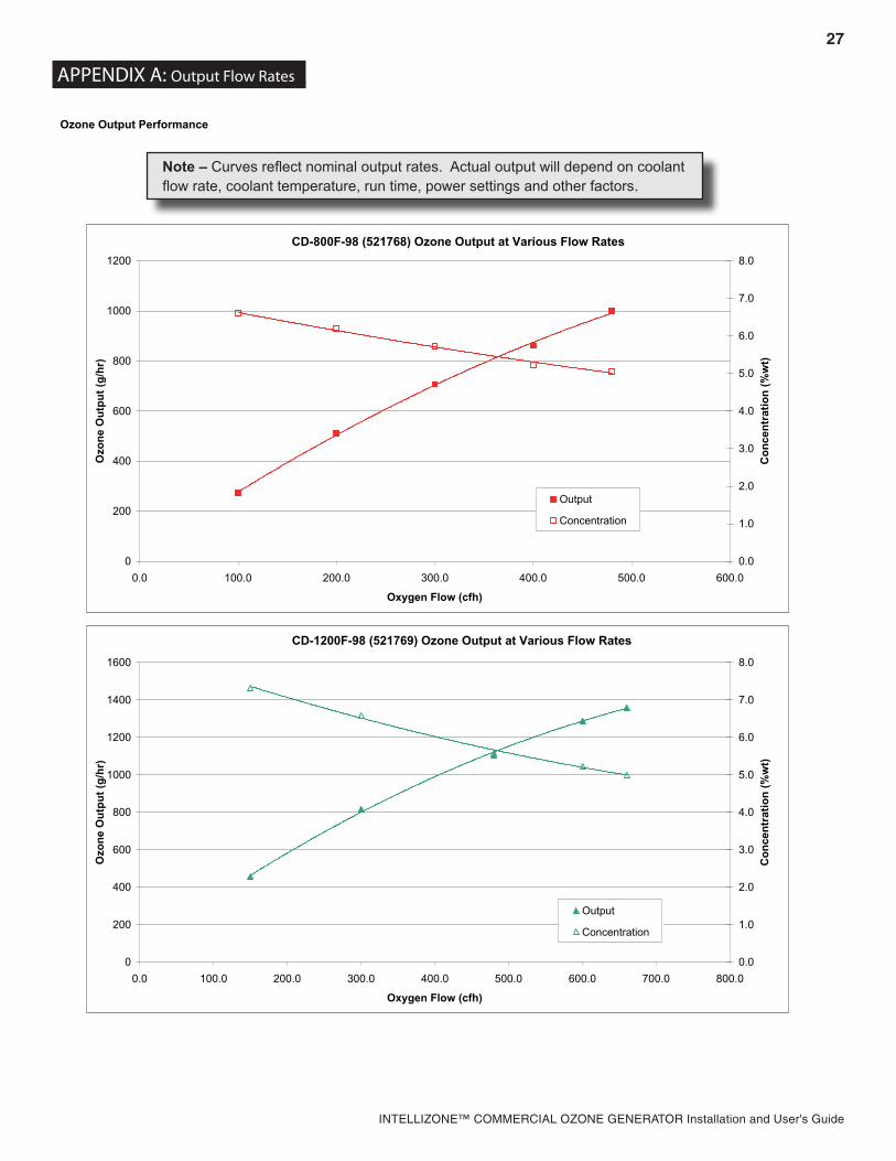
Ozone Output Performance
CD-400F (521667) Ozone Output at Various Flow Rates
Note – Curves reflect nominal output rates. Actual output will depend on coolant flow rate, coolant temperature, run time, power settings and other factors.
27
INTELLIZONE™ COMMERCIAL OZONE GENERATOR Installation and User's Guide
Ozone Output Performance
CD-800F-98 (521768) Ozone Output at Various Flow Rates
0
200
400
600
800
1000
1200
0.0 100.0 200.0 300.0 400.0 500.0 600.0
Oxygen Flow (cfh)
Ozo
ne O
utpu
t (g/
hr)
0.0
1.0
2.0
3.0
4.0
5.0
6.0
7.0
8.0
Con
cent
ratio
n (%
wt)
Output
Concentration
CD-1200F-98 (521769) Ozone Output at Various Flow Rates
Note – Curves reflect nominal output rates. Actual output will depend on coolant flow rate, coolant temperature, run time, power settings and other factors.
28
INTELLIZONE™ COMMERCIAL OZONE GENERATOR Installation and User's Guide
APPENDIX - B
29
INTELLIZONE™ COMMERCIAL OZONE GENERATOR Installation and User's Guide
APPENDIX D: Pre-Commissioning Checklist_
Customer DateJob Name Model No.Location Serial No.
Please complete one checklist for each Ozone Generator to be commissioned. Initial all items, note any exceptions/deviations observed and detail any corrective action taken or recommended.
Ozone Generator Properly anchored to mounting surface. Correct voltage supplied and connected. Coolant supply and return connected from proper source. Ozone line (stainless steel or thread seal tape) connected to outlet fitting. Flow switch (or pump interlock) connected.
Injectors Correct orientation with water flow direction. Ozone line (stainless steel or thread seal tape) connected with stainless steel ball valve and check valve
User I/O ORP and/or dissolved monitor(s) and probe(s) properly installed in accessible location for maintenance. ORP, Dissolved Ozone, Remote Standby, Remote Stop inputs properly connected (jumpered out if not
used). 4-20 mA signal properly connected if used. Input left open if unused. If used, “Ozone On” and “Fault” output signals connected correctly.
Ambient Ozone Monitor Ambient Ozone monitor interlock properly connected to user input terminal. Sensor installed per manufacturer’s instructions.
System Plumbing Contact tank(s) or mixing tower(s) properly mounted and plumbed. Degas valve(s) installed properly and plumbed to ozone destruct inlet. Main circulation system in working order including pumps, filters, heater, … Booster pump operational and ozone side-stream plumbing complete and in proper operating order.
Signed:___________________________________
_APPENDIX B: Specification Drawings_
30
INTELLIZONE™ COMMERCIAL OZONE GENERATOR Installation and User's Guide
APPENDIX D: Ozone Process System Typical Layout_
Ozone Generator
Oxygen Source
Check Valve
Bypass Valve
Process Flow Switch
Suction Control Valve
Injector
Water Dump Valve
Degas Valve
Off Gas Vent
Ozone Destruct
Coolant Source
Ozone Injector Manifold
Contact Tank
31
INTELLIZONE™ COMMERCIAL OZONE GENERATOR Installation and User's Guide
APPENDIX E: System/Controls Block Diagram_
32
INTELLIZONE™ COMMERCIAL OZONE GENERATOR Installation and User's Guide
APPENDIX F: Wiring Diagram_
33
INTELLIZONE™ COMMERCIAL OZONE GENERATOR Installation and User's Guide
APPENDIX F: Wiring Diagram, Cont._
34
INTELLIZONE™ COMMERCIAL OZONE GENERATOR Installation and User's Guide
APPENDIX G: PLC Functional Specification_
35
INTELLIZONE™ COMMERCIAL OZONE GENERATOR Installation and User's Guide
APPENDIX G: PLC Functional Specification_
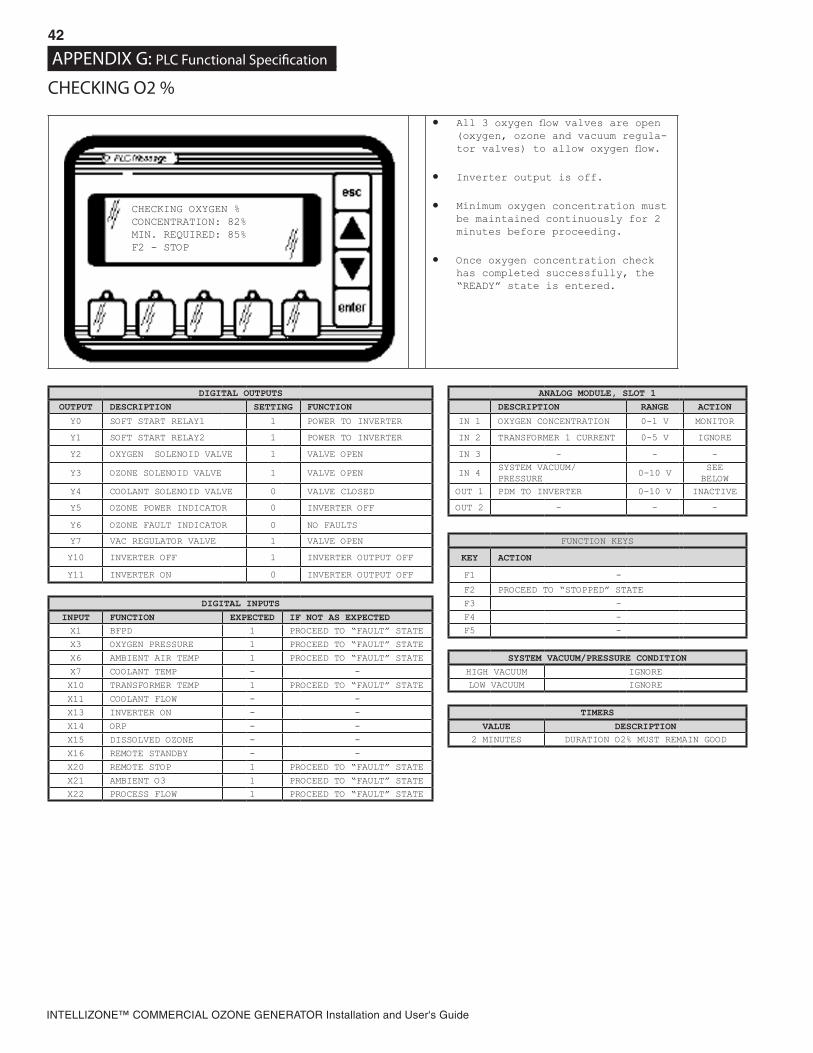
WELCOME• All valves are closed.
• Inverter output is off.
• Soft-start sequence is applied for inverters that require it.
• Model Number and Software Revi-sion are displayed.
• Welcome screen is displayed for 20 seconds, followed by an inverter soft start, and then the STOPPED screen is entered.
DIGITAL OUTPUTS ANALOG MODULE, SLOT 1OUTPUT DESCRIPTION SETTING FUNCTION DESCRIPTION RANGE ACTION
Y0 SOFT START RELAY1 1 POWER TO INVERTER IN 1 OXYGEN CONCENTRATION 0-1 V IGNORE
Y1 SOFT START RELAY2 1 POWER TO INVERTER IN 2 TRANSFORMER 1 CURRENT 0-5 V IGNORE
X6 AMBIENT AIR TEMP 1 PROCEED TO “FAULT” STATE SYSTEM VACUUM/PRESSURE CONDITIONX7 COOLANT TEMP - - HIGH VACUUM IGNORE
X10 TRANSFORMER TEMP 1 PROCEED TO “FAULT” STATE LOW VACUUM GO TO “FAULT” STATE
X11 COOLANT FLOW - -
X13 INVERTER ON - - TIMERSX14 ORP DEPENDS PROCEED TO “STARTING” IF
IN AUTO MODE AND ALL 3 SIGNALS ARE CLOSED
VALUE DESCRIPTIONX15 DISSOLVED OZONE DEPENDS NONE -
X16 REMOTE STANDBY DEPENDS
X20 REMOTE STOP 1 PROCEED TO “FAULT” STATE
X21 AMBIENT O3 1 PROCEED TO “FAULT” STATE
X22 PROCESS FLOW 1 PROCEED TO “FAULT” STATE
APPENDIX G: PLC Functional Specification_
READY - AUTO MODEPAUSED: PROCESS FLOWF2 – STOPF3 – STANDBY MODE
44
INTELLIZONE™ COMMERCIAL OZONE GENERATOR Installation and User's Guide
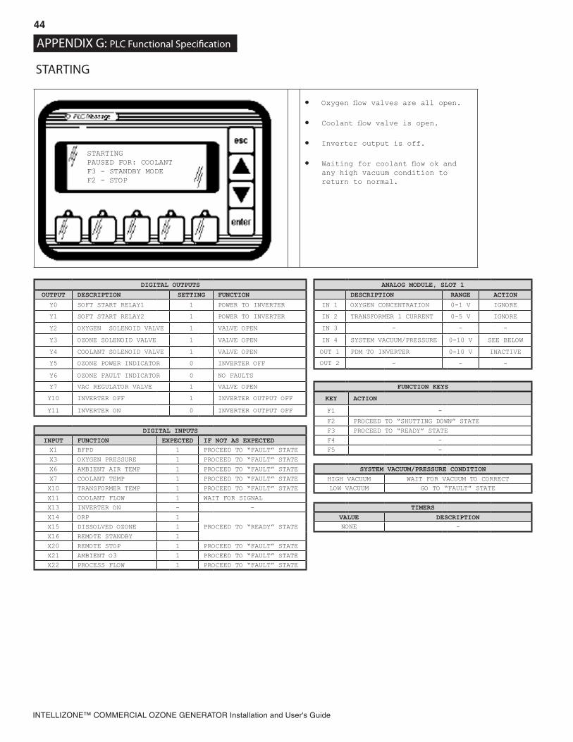
STARTING
• Oxygen flow valves are all open.
• Coolant flow valve is open.
• Inverter output is off.
• Waiting for coolant flow ok and any high vacuum condition to return to normal.
DIGITAL OUTPUTS ANALOG MODULE, SLOT 1
OUTPUT DESCRIPTION SETTING FUNCTION DESCRIPTION RANGE ACTION
Y0 SOFT START RELAY1 1 POWER TO INVERTER IN 1 OXYGEN CONCENTRATION 0-1 V IGNORE
Y1 SOFT START RELAY2 1 POWER TO INVERTER IN 2 TRANSFORMER 1 CURRENT 0-5 V IGNORE
Y2 OXYGEN SOLENOID VALVE 1 VALVE OPEN IN 3 - - -
Y3 OZONE SOLENOID VALVE 1 VALVE OPEN IN 4 SYSTEM VACUUM/PRESSURE 0-10 V SEE BELOW
Y4 COOLANT SOLENOID VALVE 1 VALVE OPEN OUT 1 PDM TO INVERTER 0-10 V INACTIVE
Y5 OZONE POWER INDICATOR 0 INVERTER OFF OUT 2 - - -
Y6 OZONE FAULT INDICATOR 0 NO FAULTS
Y7 VAC REGULATOR VALVE 1 VALVE OPEN FUNCTION KEYS
Y10 INVERTER OFF 1 INVERTER OUTPUT OFF KEY ACTION
Y11 INVERTER ON 0 INVERTER OUTPUT OFF F1 -
F2 PROCEED TO “SHUTTING DOWN” STATE
DIGITAL INPUTS F3 PROCEED TO “READY” STATE
INPUT FUNCTION EXPECTED IF NOT AS EXPECTED F4 -
X1 BFPD 1 PROCEED TO “FAULT” STATE F5 -
X3 OXYGEN PRESSURE 1 PROCEED TO “FAULT” STATE
X6 AMBIENT AIR TEMP 1 PROCEED TO “FAULT” STATE SYSTEM VACUUM/PRESSURE CONDITIONX7 COOLANT TEMP 1 PROCEED TO “FAULT” STATE HIGH VACUUM WAIT FOR VACUUM TO CORRECT
X10 TRANSFORMER TEMP 1 PROCEED TO “FAULT” STATE LOW VACUUM GO TO “FAULT” STATE
INTELLIZONE™ COMMERCIAL OZONE GENERATOR Installation and User's Guide
RUNNING
• Oxygen flow valves are all open.
• Coolant flow valve is open.
• Inverter output is ON.
• Ozone is being produced at a power setting that is controlled by PID loop control on the trans-former/inductor current as a per-centage of maximum current.
DIGITAL OUTPUTS ANALOG MODULE, SLOT 1OUTPUT DESCRIPTION SETTING FUNCTION DESCRIPTION RANGE ACTION
Y0 SOFT START RELAY1 1 POWER TO INVERTER IN 1 OXYGEN CONCENTRATION 0-1 V FAULT IF LOW
Y1 SOFT START RELAY2 1 POWER TO INVERTER IN 2 TRANSFORMER 1 CURRENT 0-5 V PID CONTROL
Y2 OXYGEN SOLENOID VALVE 1 VALVE OPEN IN 3 - - -
Y3 OZONE SOLENOID VALVE 1 VALVE OPEN IN 4 SYSTEM VACUUM/PRESSURE 0-10 V SEE BELOW
Y4 COOLANT SOLENOID VALVE 1 VALVE OPEN OUT 1 PDM TO INVERTER 0-10 V PID CONTROL
Y5 OZONE POWER INDICATOR 1 INVERTER ON OUT 2 - - -
Y6 OZONE FAULT INDICATOR 0 NO FAULTS
Y7 VAC REGULATOR VALVE 1 VALVE OPEN FUNCTION KEYS
Y10 INVERTER OFF 0 INVERTER OUTPUT ON KEY ACTION
Y11 INVERTER ON 1 INVERTER OUTPUT ON F1 -
F2 PROCEED TO “SHUTTING DOWN” STATE
DIGITAL INPUTS F3 PROCEED TO “READY” STATE
INPUT FUNCTION EXPECTED IF NOT AS EXPECTED F4 -
X1 BFPD 1 PROCEED TO “FAULT” STATE F5 -
X3 OXYGEN PRESSURE 1 PROCEED TO “FAULT” STATE
X6 AMBIENT AIR TEMP 1 PROCEED TO “FAULT” STATE SYSTEM VACUUM/PRESSURE CONDITIONX7 COOLANT TEMP 1 PROCEED TO “FAULT” STATE HIGH VACUUM GO TO “FAULT” STATE
X10 TRANSFORMER TEMP 1 PROCEED TO “FAULT” STATE LOW VACUUM GO TO “FAULT” STATE
X11 COOLANT FLOW 1 PROCEED TO “READY” STATE
X13 INVERTER ON 1 PROCEED TO “FAULT” STATE TIMERS
X14 ORP 1
PROCEED TO “READY” STATEVALUE DESCRIPTION
X15 DISSOLVED OZONE 11 SECOND
INVERTER ON DELAY TO AVOID POSSIBLE TIMING FAULT (OFF/ON TOO FAST)X16 REMOTE STANDBY 1
X20 REMOTE STOP 1 PROCEED TO “FAULT” STATE 1 SECOND O2 PRESSURE SWITCH DEBOUNCE FILTER
X21 AMBIENT O3 1 PROCEED TO “FAULT” STATE 1 SECOND WAIT FOR VALID INVERTER RELAY OUTPUT
X22 PROCESS FLOW 1 PROCEED TO “READY” STATE 10 SECONDS TIME BEFORE LOW O2% CONSIDERED TRUE
INTELLIZONE™ COMMERCIAL OZONE GENERATOR Installation and User's Guide
OZONE Material Safety Data SheetSECTION I: MATERIAL IDENTIFICATION
IDENTITY: OZONE (Gaseous) ISSUED: February, 1992FORMULA: O3 REVISED: September, 2001Description (origin/uses): Occurs in atmosphere from UV light action on oxygen at high altitude. Commercially obtained by
passing air between electrodes carrying a high voltage alternating current. Also found as a by-product in welding areas, high voltage equipment, or UV radiation.
Ozone is used as an oxidizing agent in air and water dis infection: for bleaching textiles, oils, and waxes; organic synthesis as in processing certain perfumes, vanillin, camphor; for mold and bacteria control in cold storage.
Cautions: A powerful oxidizing agent, ozone generally exists as a gas and is highly chemically reactive. Inhalation produces various degrees of respiratory effects from irritation to pulmonary edema (fluid in lungs) as well as affecting the eyes, blood, and central nervous system.
Manufacturer/Supplier: On-site generation, equipment available from various suppliers, including:DEL Industries3428 Bullock Ln. San Luis Obispo, CA 93401
Phone: (805) 541-1601FAX: (805) 541-8459
SECTION II: INGREDIENTS AND HAZARDS
Ozone, CAS No. 10028-15-6: NIOSH RTECS No. RS82250001991 OSHA PELs
-315.4° F (-193° C)100%48 Grams/MoleNot Listed10.22° F (-12.1° C)
Appearance and Odor: Colorless to blue gas (greater than -169° F): characteristic odor often associated with electrical sparks or lightning in concentrations of less than 2 ppm and becomes disagreeable above 1-2 ppm. CAUTION: Olfactory fatigue develops rapidly, so do not use odor as a preventative warning device.
SECTION IV: FIRE AND EXPLOSION HAZARD DATAFlash Point: . . . . . . . .Extinguishing Media: .
NonflammableUse large amounts of water spray or fog to put out fires involving ozone. Use appropriate fire-fightingtechniques to deal with surrounding material.
Special Fire Fighting Procedures: Wear a self contained breathing apparatus with full facepieces operated in a pressure-demand or other positive-pressure mode.
Unusual Fire/Explosion Hazards: Decomposition of ozone into oxygen gas, (O2), can increase strength of fire.
SECTION V: REACTIVITY DATA
Stability: Ozone is not stable. Hazardous polymerization cannot occur.
Chemical Incompatibilities: Ozone is chemically incompatible with all oxidizable materials, both organic and inorganic.
Conditions to Avoid: Ozone is unstable at room temperatures and spontaneously decomposes to oxygen gas. Avoid ignition sources such as heat, sparks, and open flame. Keep away from strong reducing agents and combustible materials such as grease, oils, and fats.
Products of Hazardous Decomposition: Ozone spontaneously decomposes to oxygen gas, even at room temperatures.
APPENDIX K – MSDS Sheets
51
INTELLIZONE™ COMMERCIAL OZONE GENERATOR Installation and User's Guide
SECTION VI: HEALTH HAZARD DATA
Carcinogenicity: Ozone is not listed as a carcinogen by the NTP, IARC, or OSHA.
Primary Entry: Inhalation
Target Organs: Respiratory system, eyes, blood.
Summary of Risks: There is no true threshold limit and so no exposure (regardless of how small) is theoretically without effect from ozone’s strong oxidative ability. Ozone passes straight to the smallest bronchioles and alveoli and is not absorbed by mucous membranes along the way. Initial small exposure may reduce cell sensitivity and/or increase mucous thickness producing a resistance to low ozone levels. Short exposure to 1-2 ppm concentrations causes headache as well as irritation to the respiratory tract, but symptoms subside when exposure ends. High concentrations of ozone produce severe irritation of the eyes and respiratory tract. Exposure above the ACGIH/OSHA limits produce nausea, chest pain, coughing, fatigue, reduced visual acuity, and pulmonary edema. Symptoms of edema from excessive exposure can be delayed one or more hours. Inhalation of >20 ppm for an hour or more (>50 ppm for 1/2 hour) can be fatal.
Acute Effects: Acute damage from ozone appears to be mainly from its oxidizing effect on contact with tissue.
Chronic Effects: Respiratory disease. Deleterious effects on lungs and acceleration of tumors have been reported.
Medical Conditions Generally Aggravated by Long-Term Exposure: History of respiratory or heart disorders.
First Aid: Remove from ozone containing air, get prompt medical help*, administer oxygen if necessary.Eye Contact - Gently lift eyelids and flush eyes continuously with flooding amounts of water for 15 minutes or until transported to
a medical facility*.Inhalation - Remove exposed person to fresh air, support breathing, administer humidified oxygen as needed, get medical
help*.Ingestion - Highly unlikely since ozone is a gas until -169° F,
* GET MEDICAL ASSISTANCE = APPROPRIATE IN-PLANT, PARAMEDIC, or COMMUNITY. Get prompt medical assistance for further treatment, observation, and support after first aid.
SECTION VII: PRECAUTIONS FOR SAFE HANDLING AND USE
Steps to be Taken in Case of Spill/Leak:1. Discontinue production2. Isolate and vent area3. Immediately notify personnel4. Deny entry5. Follow applicable OSHA regulations
Disposal: Provide ventilation to dilute and disperse small amounts of ozone (below OSHA PELs) to outside atmosphere. Follow federal, state, and local regulations.
Handling/Storage Precautions: Ensure proper personnel training and establish emergency procedures.
SECTION VIII: CONTROL MEASURES
Respiratory Protection: High Level (>10ppm) - Self Contained Breathing Apparatus: MISH/NIOSH approved.Low Level (0.3 - 10 ppm) - Canister Type (carbon) respirator may be used.
Eye Protection: Wear chemical safety goggles if necessary to work in high ozone (>10 ppm).
Skin Gloves: Effects of ozone on skin are minimal to non-existent.
Ventilation: Provide general and local exhaust ventilation to dilute and disperse small amounts of ozone into the outside atmosphere.
SECTION IX: SPECIAL PRECAUTIONS AND COMMENTS
Storage Segregation: Prevent ozone from coming into direct physical contact with strong acids or bases or with strong oxidizing/reducing agents.
Engineering Controls: Install ventilation systems capable of maintaining ozone to concentrations below the ACGIH/OSHA exposure limits (see sect. II). Install ambient ozone monitor(s) configured to shut down ozone equipment and turn high speed ventilation on.
QuantumTM Ozone GeneratorAPPENDIX K– MSDS Sheets
52
INTELLIZONE™ COMMERCIAL OZONE GENERATOR Installation and User's Guide
Page 1 of 3
4-1444-01_Rev.C
Material Safety Data Sheet This MSDS complies with OSHA’s Hazardous Communication Standard 29 CFR 1910.1200 and OSHA form 174.
DEL Ozone 3580 Sueldo Street San Luis Obispo, CA 93401 Product Information 805-541-1601
Product Name AQUEOUS OZONE SOLUTION
Chemical Name DISSOLVED OZONE GAS IN WATER 0 TO 2 PPM
Product Description AQUEOUS SOLUTION OF OZONE DISSOLVED IN POTABLE WATER
D.O.T. Shipping Classification NON REGULATED
I PHYSICAL DATA
Boiling Point 212 F Freezing Point 32 F
Specific Gravity 1.0 Solubility in Water COMPLETE
Evaporation Rate APPROX 1 Physical Form LIQUID
Appearance & Odor COLORLESS (CLEAR) WATER WITH FRESH, ASEPTIC ODOR
II HAZARDOUS INGREDIENTS
MATERIAL HAZARD CAS # % BY WT ACGIH TLV OSHA PEL
None
III FIRE AND EXPLOSION HAZARD DATA
Flash Point NA Method NA Auto Ign. Temp. NA Flammable Limits in Air NON APPLICABLE Lower NA Upper NA
Extinguishing Media NON APPLICABLE Unusual Fire & Explosion Hazards NONE
INTELLIZONE™ COMMERCIAL OZONE GENERATOR Installation and User's Guide
Page 2 of 3
4-1444-01_Rev.C
Material Safety Data Sheet Cont.
Product Name AQUEOUS OZONE SOLUTION
IV HEALTH HAZARD DATA
Threshold Limit Value NOT DETERMINED
Route of Exposure Inhalation Ingestion Skin Eye Not Hazardous
Eye Contact Hazard Exposure may cause mild eye irritation, but is not expected.
Ingestion Hazard Not Hazardous
Inhalation Hazard Inhalation is not likely to be a primary route of exposure but could become irritating if aerosols are exposed to individual for extended period of time.
Skin Contact Hazard No skin irritation is expected from short term exposure.
Skin Absorption Hazard No published data indicates this product is absorbed through the skin.
Effects of Acute Exposure Mild skin or eye irritation.
Effects of Chronic Exposure
Repeated exposure of the skin to concentrated product should be avoided to prevent irritation and drying of the skin.
V EMERGENCY AND FIRST AID PROCEDURES
Eye Contact If exposure to water containing aqueous solution of ozone causes irritation to eyes, flush eyes with plenty of clean, ozone free, running water for at least 15 minutes, lifting the upper and lower lids occasionally. Remove contact lenses if worn. Seek medical attention if irritation persists.
Skin Contact Not likely to become irritated unless repeatedly exposed to large volumes of material. If irritation develops, rinse affected area with ozone free potable water. If irritation continues seek medical advice.
Inhalation Inhalation of mists could lead to irritation of lungs. If symptoms develop, move individual away from exposure and into fresh air. If symptoms persist, seek medical attention.
Ingestion NA
VI REACTIVITY DATA
Incompatibility (Materials to Avoid) Natural rubber (may degrade, or “dry”, rubber components over extended periods of exposure)
Conditions to Avoid NONE KNOWN
Hazardous Decomposition NONE
Stability STABLE UNSTABLE Hazardous Polymerization MAY OCCUR WILL NOT OCCUR
APPENDIX K – MSDS Sheets
54
INTELLIZONE™ COMMERCIAL OZONE GENERATOR Installation and User's Guide
Page 3 of 3
4-1444-01_Rev.C
Material Safety Data Sheet Cont.
Product Name AQUEOUS OZONE SOLUTION
VII SPILL OR LEAK PROCEDURES
Steps To Be Taken If Material Is Released Or Spilled
NONE
Waste Disposal Method DISPOSE OF THE SAME AS POTABLE RINSE WATER
VIII SPECIAL PROTECTIVE INFORMATION
Respiratory Protection (Specify Type) NOT REQUIRED FOR NORMAL USE OF THIS PRODUCT
LocalExhaust PREFERABLE Special NA
VentilationMechanical (general) OK Other NA
Protective Gloves NOT REQUIRED
Eye Protection NOT REQUIRED
Other Protective Equipment NOT REQUIRED
IX SPECIAL PRECAUTIONS
Precautionary Labeling
Certified testing of DEL Ozone systems by NSF (National Sanitation Foundation) has shown that under normal conditions of use, aqueous solutions containing low levels of ozone gas dissolved in potable water do not present a safety hazard when contact to the individual is incidental. When used in a room with normal ventilation, levels of ozone gas being released into the air have been shown by NSF to be well below the periodic exposure levels established by OSHA for worker safety through the use of DEL’s ozone management technology.
Precautions To Be Taken In Handling
Aqueous solutions of ozone in potable water should not be sprayed as an aerosol (i.e. >20psi) to avoid releasing higher levels of ozone gas into the work area. The decay rate of ozone gas is a function of temperature and exposure to organic material. Certified testing has shown that when ozone gas has been properly dissolved in ambient temperature (or colder (33 – 70 °F)) potable water at a level not exceeding 2 mg/l (ppm) using DEL’s ozone management technology, the rate at which ozone is released from the water as ozone gas is below the PEL established for gaseous ozone.
Rev. Date 03/26/12
This material safety data sheet is provided as an information resource only. It should not be taken as a warranty or representation for which the preparer assumes legal responsibility. While we believe the information contained herein is accurate and compiled from sources believed to be reliable, it is the responsibility of the user to investigate and verify its validity. The buyer assumes all responsibility of using and handling the product in accordance with applicable federal, state, and local regulations.
APPENDIX K – MSDS Sheets
55
INTELLIZONE™ COMMERCIAL OZONE GENERATOR Installation and User's Guide
4-0697_ Rev.C
OZONE Material Safety Data Sheet SECTION I: MATERIAL IDENTIFICATION
IDENTITY: OZONE (Gaseous) ISSUED: February, 1992 FORMULA: O3 REVISED: April 3, 2012 Description (origin/uses): Occurs in atmosphere from UV light action on oxygen at high altitude. Commercially obtained by
passing air between electrodes carrying a high voltage alternating current. Also found as a by-product in welding areas, high voltage equipment, or UV radiation.Ozone is used as an oxidizing agent in air and water disinfection: for bleaching textiles, oils, and waxes; organic synthesis as in processing certain perfumes, vanillin, camphor; for mold and bacteria control in cold storage.
Cautions: A powerful oxidizing agent, ozone generally exists as a gas and is highly chemically reactive. Inhalation produces various degrees of respiratory effects from irritation to pulmonary edema (fluid in lungs) as well as affecting the eyes, blood, and central nervous system.
Manufacturer/Supplier: On-site generation, equipment available from various suppliers, including:DEL Ozone 3580 Sueldo Street San Luis Obispo, CA 93401
Phone: (805) 541-1601 FAX: (805) 541-8459
SECTION II: INGREDIENTS AND HAZARDS
Ozone, CAS No. 10028-15-6: NIOSH RTECS No. RS82250001991 OSHA PELs
-315.4 F (-193 C) 100%48 Grams/Mole Not Listed 10.22 F (-12.1 C)
Appearance and Odor: Colorless to blue gas (greater than -169 F): characteristic odor often associated with electrical sparks or lightning in concentrations of less than 2 ppm and becomes disagreeable above 1-2 ppm. CAUTION: Olfactory fatigue develops rapidly, so do not use odor as a preventative warning device.
SECTION IV: FIRE AND EXPLOSION HAZARD DATA Flash Point: . . . . . . . . Extinguishing Media: .
NonflammableUse large amounts of water spray or fog to put out fires involving ozone. Use appropriate fire-fighting techniques to deal with surrounding material.
Special Fire Fighting Procedures: Wear a self contained breathing apparatus with full face pieces operated in a pressure-demand or other positive-pressure mode.
Unusual Fire/Explosion Hazards: Decomposition of ozone into oxygen gas, (O2), can increase strength of fire.
SECTION V: REACTIVITY DATA
Stability: Ozone is not stable. Hazardous polymerization cannot occur.
Chemical Incompatibilities: Ozone is chemically incompatible with all oxidizable materials, both organic and inorganic.
Conditions to Avoid: Ozone is unstable at room temperatures and spontaneously decomposes to oxygen gas. Avoid ignition sources such as heat, sparks, and open flame. Keep away from strong reducing agents and combustible materials such as grease, oils, and fats.
Products of Hazardous Decomposition: Ozone spontaneously decomposes to oxygen gas, even at room temperatures.
56
INTELLIZONE™ COMMERCIAL OZONE GENERATOR Installation and User's Guide
4-0697_ Rev.C
SECTION VI: HEALTH HAZARD DATA
Carcinogenicity: Ozone is not listed as a carcinogen by the NTP, IARC, or OSHA.
Primary Entry: Inhalation
Target Organs: Respiratory system, eyes, blood.
Summary of Risks: There is no true threshold limit and so no exposure (regardless of how small) is theoretically without effect from ozone’s strong oxidative ability. Ozone passes straight to the smallest bronchioles and alveoli and is not absorbed by mucous membranes along the way. Initial small exposure may reduce cell sensitivity and/or increase mucous thickness producing a resistance to low ozone levels. Short exposure to 1-2 ppm concentrations causes headache as well as irritation to the respiratory tract. but symptoms subside when exposure ends. High concentrations of ozone produce severe irritation of the eyes and respiratory tract. Exposure above the ACGIH/OSHA limits produce nausea, chest pain, coughing, fatigue, reduced visual acuity, and pulmonary edema. Symptoms of edema from excessive exposure can be delayed one or more hours. Inhalation of >20 ppm for an hour or more (>50 ppm for 1/2 hour) can be fatal.
Acute Effects: Acute damage from ozone appears to be mainly from its oxidizing effect on contact with tissue.
Chronic Effects: Respiratory disease. Deleterious effects on lungs and acceleration of tumors have been reported.
Medical Conditions Generally Aggravated by Long-Term Exposure: History of respiratory or heart disorders.
First Aid: Remove from ozone containing air, get prompt medical help*, administer oxygen if necessary. Eye Contact - Gently lift eyelids and flush eyes continuously with flooding amounts of water for 15 minutes or until transported to a
medical facility*. Inhalation - Remove exposed person to fresh air, support breathing, administer humidified oxygen as needed, get medical help*. Ingestion - Highly unlikely since ozone is a gas until -169 F,
* GET MEDICAL ASSISTANCE = APPROPRIATE IN-PLANT, PARAMEDIC, or COMMUNITY. Get prompt medical assistance for further treatment, observation, and support after first aid.
SECTION VII: PRECAUTIONS FOR SAFE HANDLING AND USE
Steps to be Taken in Case of Spill/Leak:1. Discontinue production 2. Isolate and vent area 3. Immediately notify personnel 4. Deny entry 5. Follow applicable OSHA regulations
Disposal: Provide ventilation to dilute and disperse small amounts of ozone (below OSHA PELs) to outside atmosphere. Follow federal, state, and local regulations.
Handling/Storage Precautions: Ensure proper personnel training and establish emergency procedures.
SECTION VIII: CONTROL MEASURES
Respiratory Protection: High Level (>10 ppm) - Self Contained Breathing Apparatus: MISH/NIOSH approved. Low Level (0.3 - 10 ppm) - Canister Type (carbon) respirator may be used.
Eye Protection: Wear chemical safety goggles if necessary to work in high ozone (>10 ppm).
Skin Protection: Effects of ozone on skin are minimal to non-existent.
Ventilation: Provide general and local exhaust ventilation to dilute & disperse small amounts of ozone into outside atmosphere.
SECTION IX: SPECIAL PRECAUTIONS AND COMMENTS
Storage Segregation: Prevent ozone from coming into direct physical contact with strong acids or bases or with strong oxidizing/reducing agents.
Engineering Controls: Install ventilation systems capable of maintaining ozone to concentrations below the ACGIH/OSHA exposure limits (see sect. II). Install ambient ozone monitor(s) configured to shut down ozone equipment and turn high speed ventilation on.
57
INTELLIZONE™ COMMERCIAL OZONE GENERATOR Installation and User's Guide
This document is subject to change without notice.
1620 Hawkins Ave., Sanford, NC 27330 • (919) 566-800010951 West Los Angeles Ave., Moorpark, CA 93021 • (805) 553-5000 All Pentair trademarks and logos are owned by Pentair, Inc. Pentair Aquatic Systems™ and IntelliZone™ are trademarks and/or registered trademarks of Pentair Water Pool and Spa, Inc. and/or its affiliated companies in the United States and/ or other countries. Unless expressly noted, names and brands of third parties that may be used in this document are not used to indicate an affiliation or endorsement between the owners of these names and brands and Pentair Water Pool and Spa, Inc. Those names and brands may be the trademarks or registered trademarks of those third parties. Because we are continuously improving our products and services, Pentair reserves the right to change specifications without prior notice. Pentair is an equal opportunity employer.