42
Commissioning TCSM2 dn0195206 Issue 2-0 en # Nokia Corporation Nokia Proprietary and Confidential 1 (42) 2003353 Nokia BSC/TCSM S11.5 Product Documentation
Commissioning TCSM2
dn0195206Issue 2-0 en
# Nokia CorporationNokia Proprietary and Confidential
1 (42)
2003353Nokia BSC/TCSM S11.5 ProductDocumentation
The information in this documentation is subject to change without notice and describes only theproduct defined in the introduction of this documentation. This documentation is intended for theuse of Nokia's customers only for the purposes of the agreement under which the documentationis submitted, and no part of it may be reproduced or transmitted in any form or means without theprior written permission of Nokia. The documentation has been prepared to be used byprofessional and properly trained personnel, and the customer assumes full responsibility whenusing it. Nokia welcomes customer comments as part of the process of continuous developmentand improvement of the documentation.
The information or statements given in this documentation concerning the suitability, capacity, orperformance of the mentioned hardware or software products cannot be considered binding butshall be defined in the agreement made between Nokia and the customer. However, Nokia hasmade all reasonable efforts to ensure that the instructions contained in the documentation areadequate and free of material errors and omissions. Nokia will, if necessary, explain issueswhich may not be covered by the documentation.
Nokia's liability for any errors in the documentation is limited to the documentary correction oferrors. NOKIA WILL NOT BE RESPONSIBLE IN ANY EVENT FOR ERRORS IN THISDOCUMENTATION OR FOR ANY DAMAGES, INCIDENTAL OR CONSEQUENTIAL(INCLUDING MONETARY LOSSES), that might arise from the use of this documentation or theinformation in it.
This documentation and the product it describes are considered protected by copyrightaccording to the applicable laws.
NOKIA logo is a registered trademark of Nokia Corporation.
Other product names mentioned in this documentation may be trademarks of their respectivecompanies, and they are mentioned for identification purposes only.
Copyright © Nokia Corporation 2005. All rights reserved.
2 (42) # Nokia CorporationNokia Proprietary and Confidential
dn0195206Issue 2-0 en
Commissioning TCSM2
Contents
Contents 3
List of tables 4
List of figures 5
Summary of changes 7
1 Commissioning TCSM2 9
2 Introduction to TCSM2 commissioning 11
3 Checking the hardware functions 15
4 Configuring the TCSM2 unit 174.1 Introduction 174.2 Checking the PCM circuit terminal type 174.3 Automatic loading of the software 184.4 Loading the software from diskette 184.5 Uploading and downloading the configuration files 214.6 Configuring the transcoder PCM types 214.7 Configuring the synchronization 234.8 Configuring the E1 interfaces (ETSI) 244.9 Configuring the T1 interfaces (ANSI) 274.10 Other transcoder configuration procedures (ETSI, ANSI) 304.11 Configuring Acoustic Echo Cancellation (optional) 334.12 Configuring Tandem Free Operation (optional) 334.13 Configuring Noise Suppression (optional) 344.14 Alarm handling 354.15 Saving the configuration 38
5 Testing the TCSM2 unit configurations 395.1 Running the diagnostics tests 395.2 Testing the power supply alarms of the TCSM2 415.3 Testing power break recovery in the TCSM2 41
dn0195206Issue 2-0 en
# Nokia CorporationNokia Proprietary and Confidential
3 (42)
Contents
List of tables
Table 1. Voltage requirements. 16
Table 2. Transcoder circuit types. 22
4 (42) # Nokia CorporationNokia Proprietary and Confidential
dn0195206Issue 2-0 en
Commissioning TCSM2
List of figures
Figure 1. The operating environment of the TCSM2. 12
Figure 2. A far-end alarm handling example, AIS is sent to the MSC. 36
Figure 3. A far-end alarm handling example, AIS is sent to the MSC. 37
Figure 4. Alarm test 41
dn0195206Issue 2-0 en
# Nokia CorporationNokia Proprietary and Confidential
5 (42)
List of figures

6 (42) # Nokia CorporationNokia Proprietary and Confidential
dn0195206Issue 2-0 en
Commissioning TCSM2
Summary of changes
Summary of changes
Changes between document issues are cumulative. Therefore, the latest documentissue contains all changes made to previous issues.
Changes between issues 1-2 and 2-0
Information on the TCSM2A-C removed.
Changes between issues 1-1 and 1-2
Structural corrections; no effect on the contents of the document.
Changes between issues 1-0 and 1-1
In ANSI environment, the following feature added: Text Telephony (TTY).
Changes for Issue 1-0
This document contains the information earlier presented in separatecommissioning documents for the TSCM2E and TCSM2A. The following(optional) feature added: Adaptive Multirate (AMR). Online modifications made.
dn0195206Issue 2-0 en
# Nokia CorporationNokia Proprietary and Confidential
7 (42)
Summary of changes

8 (42) # Nokia CorporationNokia Proprietary and Confidential
dn0195206Issue 2-0 en
Commissioning TCSM2
1 Commissioning TCSM2
This document explains the basic commissioning procedures for the TCSM2E orTCSM2A unit. Detailed installation and operating instructions are provided in thecorresponding manuals.
This document describes how to configure the TCSM2E or TCSM2A transcodersand test the connections. The presumption is that the plug-in units are new or infactory equivalent condition, so that they will work as intended if properlyconfigured.
This manual provides the following information:
. Introduction to TCSM2 commissioning
. Checking the hardware functions
. Configuring the TCSM2 unit
. Testing the TCSM2 unit configurations
dn0195206Issue 2-0 en
# Nokia CorporationNokia Proprietary and Confidential
9 (42)
Commissioning TCSM2

10 (42) # Nokia CorporationNokia Proprietary and Confidential
dn0195206Issue 2-0 en
Commissioning TCSM2

2 Introduction to TCSM2 commissioningPrerequisite
First make a T1/E1 time slot usage plan for each A interface T1 circuit (line) inthe TCSM2A, and E1 circuit in the TCSM2E. The following issues are critical:
. how many speech channels are used
. how many through-connected channels, such as Common ChannelSignalling (CCS) and X.25 are used
This usage plan must be co-ordinated with the configuration plans of the BSCand the MSC.
Testing environment
This commissioning manual is a stand-alone document, in the sense that itdescribes the tests on transcoders and associated transmission equipment that donot require the presence of the BSC or MSC. In practice, the tests are oftenperformed with the operating BSC and MSC. Thus, making test calls as the finalcommissioning step is sometimes not necessary, because such tests are includedin the commissioning of the BSC and MSC. Separate TCSM2E/TCSM2Acommissioning test calls are, however, strongly recommended.
Extending an already working Base Station Subsystem (BSS) requires slightlydifferent commissioning procedures and more care not to disturb traffic. Fordetails, see the appropriate commissioning and integration manuals.
Equipment and module architecture
The figure below presents the general location of the TCSM2 in the operatingenvironment of the GSM/PCS network. TCSM2 can be placed at the BSC orMSC site.
dn0195206Issue 2-0 en
# Nokia CorporationNokia Proprietary and Confidential
11 (42)
Introduction to TCSM2 commissioning
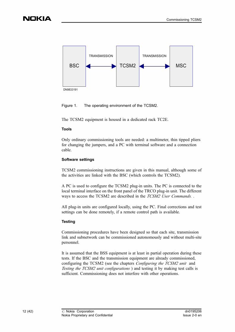
Figure 1. The operating environment of the TCSM2.
The TCSM2 equipment is housed in a dedicated rack TC2E.
Tools
Only ordinary commissioning tools are needed: a multimeter, thin tipped pliersfor changing the jumpers, and a PC with terminal software and a connectioncable.
Software settings
TCSM2 commissioning instructions are given in this manual, although some ofthe activities are linked with the BSC (which controls the TCSM2).
A PC is used to configure the TCSM2 plug-in units. The PC is connected to thelocal terminal interface on the front panel of the TRCO plug-in unit. The differentways to access the TCSM2 are described in the TCSM2 User Commands. .
All plug-in units are configured locally, using the PC. Final corrections and testsettings can be done remotely, if a remote control path is available.
Testing
Commissioning procedures have been designed so that each site, transmissionlink and subnetwork can be commissioned autonomously and without multi-sitepersonnel.
It is assumed that the BSS equipment is at least in partial operation during thesetests. If the BSC and the transmission equipment are already commissioned,configuring the TCSM2 (see the chapters Configuring the TCSM2 unit andTesting the TCSM2 unit configurations ) and testing it by making test calls issufficient. Commissioning does not interfere with other operations.
BSC
TRANSMISSION TRANSMISSION
DN9833191
TCSM2 MSC
12 (42) # Nokia CorporationNokia Proprietary and Confidential
dn0195206Issue 2-0 en
Commissioning TCSM2

Notes
In case of a problem, try the following corrective actions in this order:
. check the alarms
. check configuration settings
. check versions of loaded software packages
. check cabling
. check jumper settings (strappings)
. check firmware version
. check hardware version of the plug-in unit
. change the plug-in unit
If needed, the whole unit or any plug-in unit can be reset with a command.
Commissioning TCSM2
dn0195206Issue 2-0 en
# Nokia CorporationNokia Proprietary and Confidential
13 (42)
Introduction to TCSM2 commissioning
14 (42) # Nokia CorporationNokia Proprietary and Confidential
dn0195206Issue 2-0 en
Commissioning TCSM2
3 Checking the hardware functionsChecking the installation visually
A prerequisite for commissioning activity is that the on-site installation has beencompleted. The cabling must also be installed in advance.
Checking the interchangeability versions
Check the interchangeability versions of cartridges and plug-in units bycomparing them to the Hardware Revisions List in the Site Documents .
Checking the firmware versions
Unplug the TRCO and ET2E/ET2A boards from the cartridge and check that thefirmware (PROM) versions are approved for the application.
Checking the hardware versions and settings
Check that the hardware versions are as specified. Confirm that the hardwaresettings (strappings) of the plug-in units are in accordance with the jumper settingplan for each piece of equipment. It is assumed that the jumper settings of theplug-in units conform to the application. This may be verified by consulting theappropriate plug-in unit descriptions or the Jumper Setting Instructions.
Checking the power supply
First check that all plug-in units are disconnected from their rear connectors (theplug-in units may remain inside the cartridges).
Next, measure the supply voltages at the rear of the cartridges using a multimeter.Connectors available for power supply are:
. PL1 and PL2 in the TC1C cartridge
. PL1 and PL2 in the ET1TC cartridge
Typically the voltage is -48 V (-60 V), with a variance of about ±10 %. To verifythe power supply connections, check the input voltage of each new TCSM2 unitof the rack.
dn0195206Issue 2-0 en
# Nokia CorporationNokia Proprietary and Confidential
15 (42)
Checking the hardware functions
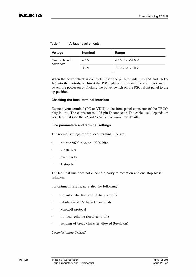
Table 1. Voltage requirements.
Voltage Nominal Range
Feed voltage toconverters
-48 V -40.5 V to -57.0 V
-60 V -50.0 V to -72.0 V
When the power check is complete, insert the plug-in units (ET2E/A and TR12/16) into the cartridges. Insert the PSC1 plug-in units into the cartridges andswitch the power on by flicking the power switch on the PSC1 front panel to theup position.
Checking the local terminal interface
Connect your terminal (PC or VDU) to the front panel connector of the TRCOplug-in unit. The connector is a 25-pin D connector. The cable used depends onyour terminal (see the TCSM2 User Commands for details).
Line parameters and terminal settings
The normal settings for the local terminal line are:
. bit rate 9600 bit/s or 19200 bit/s
. 7 data bits
. even parity
. 1 stop bit
The terminal line does not check the parity at reception and one stop bit issufficient.
For optimum results, note also the following:
. no automatic line feed (auto wrap off)
. tabulation at 16 character intervals
. xon/xoff protocol
. no local echoing (local echo off)
. sending of break character allowed (break on)
Commissioning TCSM2
16 (42) # Nokia CorporationNokia Proprietary and Confidential
dn0195206Issue 2-0 en
Commissioning TCSM2
4 Configuring the TCSM2 unit
Commissioning TCSM2
4.1 Introduction
The TCSM2 equipment is delivered with the software pre-loaded into the TRCO,TR16/TR12 and ET2E/ET2A plug-in units at the factory. Software loading is,therefore, not usually required during commissioning.
Configuring the TCSM2 unit
4.2 Checking the PCM circuit terminal type
The unit is provided with the PCM circuit terminal type, which should be set toETSI (TCSM2E) or ANSI (TCSM2A), when required.
TCSM2E (ETSI)
The unit is provided with the PCM circuit terminal type, which should be ETSI. Ifset to ANSI, change the PCM circuit terminal type to ETSI with the command:
ZGL:ETSI;
PLEASE CONFIRM (Y/N)
/* COMMAND EXECUTED */
TCSM2A (ANSI)
. If required (set to ETSI) change the PCM circuit terminal to ANSI with thecommand:
ZGL:ANSI;
PLEASE CONFIRM (Y/N)
dn0195206Issue 2-0 en
# Nokia CorporationNokia Proprietary and Confidential
17 (42)
Configuring the TCSM2 unit
/* COMMAND EXECUTED */
Configuring the TCSM2 unit
4.3 Automatic loading of the software
Start the TCSM2A by using a cold restart (by switching the power on) or warmrestart (by giving a command). When the LAPD connection to the BSC isestablished, the TCSM2 checks the consistency of the TRCO, TR16/TR12 andET2E/ET2A software with the BSC at the start-up command. If the software inthe BSC is a newer version or the checksum is different, the software is loadedfrom the BSC.
Note
The TR16/TR12 software is always automatically loaded to location 1.
The loading takes about three minutes and the results are displayed on the screen.After the restart, the local user interface informs that it is ready with the followingmessage:
TCSM LOCAL TERMINAL INTERFACE READY
Check the loaded software versions with the commands: ZGI:TRCO, ZGI:TRand ZGI:ET.
Configuring the TCSM2 unit
4.4 Loading the software from diskette
If a backup installation diskette has been purchased, the TCSM2 softwaredelivered in the diskette can be loaded into the TRCO plug-in unit duringcommissioning, if connection to the BSC is not available. The TRCO is providedwith boot software.
18 (42) # Nokia CorporationNokia Proprietary and Confidential
dn0195206Issue 2-0 en
Commissioning TCSM2
Note
Manual loading is impossible if the LAPD connection to the BSC is establishedand working.
Loading procedure
1. Check that the entire TCSM2 unit is installed properly in the rack and thatthe jumper (hardware) settings for the whole TCSM2 unit, ET2A/ET2Eplug-in units and the PSAs at the top of the rack are set correctly.
2. Connect the PC to the local terminal interface on the front panel of theTRCO plug-in unit and insert the software diskette in drive A. Note thatyou should connect the PC to the main voltage through a protectivetransformer. Make sure that the data rates between the PC and TRCOmatch (see the TCSM2 User Commands, System requirements)
3. Switch the power on from the PSC1 plug-in unit
4. After the TRCO unit starts up and completes its initialization procedure,the boot software gives a message
THERE IS NO PROGRAM CODE ON TRCO UNIT.
TRCO IS READY TO RECEIVE PROGRAM CODE.
START KERMIT FILE TRANSFER FROM YOUR COMPUTER.
5. Start the Kermit data transfer program. The unit restarts automatically afterthe code loading and begins running the code from flash memory. Seebelow for detailed instructions.
6. Load the other software components (ET2E/ET2A and DSP) by using themenu commands ZGU:TR and ZGU:ET.
Updating the software
This section describes how to update the software of the ET plug-in unit, theTRCO plug-in unit, and the transcoder TR16/TR12 in the flash memory.
1. Update the TRCO plug-in unit software.
ZGU:TRCO;
Note that the unit restarts and the program is executed from the bootPROM.
READY TO RECEIVE PROGRAM CODE
(start data transfer using Kermit protocol)
dn0195206Issue 2-0 en
# Nokia CorporationNokia Proprietary and Confidential
19 (42)
Configuring the TCSM2 unit
(When the software is updated, the TRCO unit
restarts and begins to perform the program
code just loaded)
2. Update the ET plug-in unit software
ZGU:ET;
READY TO RECEIVE PROGRAM CODE
(start data transfer using Kermit protocol)
PROGRAM TRANSFER SUCCESSFULLY COMPLETED
/* COMMAND EXECUTED */
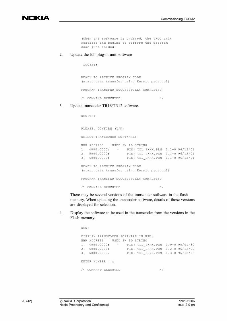
3. Update transcoder TR16/TR12 software.
ZGU:TR;
PLEASE, CONFIRM (Y/N)
SELECT TRANSCODER SOFTWARE:
NBR ADDRESS USED SW ID STRING
1. 4000.0000: * PID: TDL_PXMX.PRM 1.1-0 96/12/01
2. 5000.0000: PID: TDL_PXMX.PRM 1.1-0 96/12/01
3. 6000.0000: PID: TDL_PXMX.PRM 1.1-0 96/12/01
READY TO RECEIVE PROGRAM CODE
(start data transfer using Kermit protocol)
PROGRAM TRANSFER SUCCESSFULLY COMPLETED
/* COMMAND EXECUTED */
There may be several versions of the transcoder software in the flashmemory. When updating the transcoder software, details of those versionsare displayed for selection.
4. Display the software to be used in the transcoder from the versions in theFlash memory.
ZGW;
DISPLAY TRANSCODER SOFTWARE IN USE:
NBR ADDRESS USED SW ID STRING
1. 4000.0000: * PID: TDL_PXMX.PRM 1.9-0 98/01/30
2. 5000.0000: PID: TDL_PXMX.PRM 1.2-0 96/12/02
3. 6000.0000: PID: TDL_PXMX.PRM 1.3-0 96/12/03
ENTER NUMBER : x
/* COMMAND EXECUTED */
20 (42) # Nokia CorporationNokia Proprietary and Confidential
dn0195206Issue 2-0 en
Commissioning TCSM2
Configuring the TCSM2 unit
4.5 Uploading and downloading the configuration files
The configuration files of the configured (commissioned) transcoder can beuploaded from the transcoder to the PC using Kermit protocol. The commandcombines the active files in the RAM memory (ETCONF, TR1CON andCLKCON) into one file and sends it to the PC. The command is only possible ina local session.
This feature can be used for configuring the other transcoders in the system whenone transcoder is completed. You cannot read the files in your PC, but onlydownload and upload the whole file. When you have downloaded the file to thenew transcoder, you can modify the settings using the individual commandsdescribed in this document.
. To download the active configuration from the PC, give the command:ZGN
. To upload the active configuration to the PC, give the command: ZGO
Configuring the TCSM2 unit
4.6 Configuring the transcoder PCM types
Automatic configuration by the BSC
After a restart of the TCSM2A or after any LAPD breaks, the BSC automaticallyupdates the TCSM2A's configuration settings: the number of plug-in units, thePCM types (FR, DR, HR) and the synchronization input. If the LAPD connectionis not established or not working, you can use the local command (ZRR), seesection Local configuration manually below.
Local configuration manually
The same configuration settings of the TCSM2, which are automaticallyconfigured by the BSC, can be set here, provided that the link to the BSC isdown. If the link to the BSC is up, the command will not be accepted. Thecommand (ZRR) of the Transcoder Configuration Commands allows you to setthe transcoder PCM type which are shown in the table below.
dn0195206Issue 2-0 en
# Nokia CorporationNokia Proprietary and Confidential
21 (42)
Configuring the TCSM2 unit
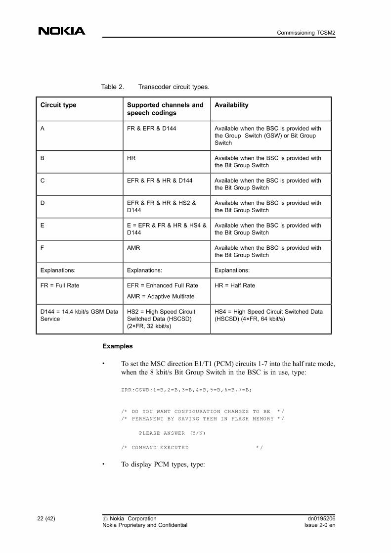
Table 2. Transcoder circuit types.
Circuit type Supported channels andspeech codings
Availability
A FR & EFR & D144 Available when the BSC is provided withthe Group Switch (GSW) or Bit GroupSwitch
B HR Available when the BSC is provided withthe Bit Group Switch
C EFR & FR & HR & D144 Available when the BSC is provided withthe Bit Group Switch
D EFR & FR & HR & HS2 &D144
Available when the BSC is provided withthe Bit Group Switch
E E = EFR & FR & HR & HS4 &D144
Available when the BSC is provided withthe Bit Group Switch
F AMR Available when the BSC is provided withthe Bit Group Switch
Explanations: Explanations: Explanations:
FR = Full Rate EFR = Enhanced Full Rate
AMR = Adaptive Multirate
HR = Half Rate
D144 = 14.4 kbit/s GSM DataService
HS2 = High Speed CircuitSwitched Data (HSCSD)(2×FR, 32 kbit/s)
HS4 = High Speed Circuit Switched Data(HSCSD) (4×FR, 64 kbit/s)
Examples
. To set the MSC direction E1/T1 (PCM) circuits 1-7 into the half rate mode,when the 8 kbit/s Bit Group Switch in the BSC is in use, type:
ZRR:GSWB:1=B,2=B,3=B,4=B,5=B,6=B,7=B;
/* DO YOU WANT CONFIGURATION CHANGES TO BE */
/* PERMANENT BY SAVING THEM IN FLASH MEMORY */
PLEASE ANSWER (Y/N)
/* COMMAND EXECUTED */
. To display PCM types, type:
22 (42) # Nokia CorporationNokia Proprietary and Confidential
dn0195206Issue 2-0 en
Commissioning TCSM2
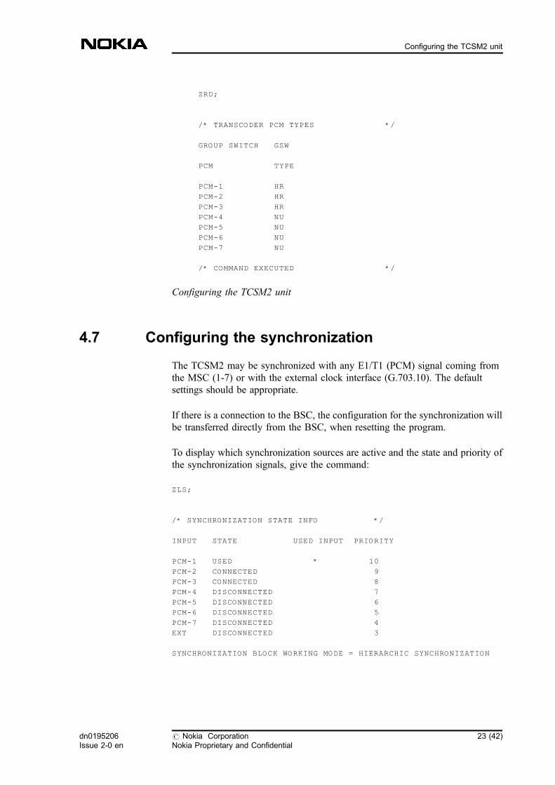
ZRD;
/* TRANSCODER PCM TYPES */
GROUP SWITCH GSW
PCM TYPE
PCM-1 HR
PCM-2 HR
PCM-3 HR
PCM-4 NU
PCM-5 NU
PCM-6 NU
PCM-7 NU
/* COMMAND EXECUTED */
Configuring the TCSM2 unit
4.7 Configuring the synchronization
The TCSM2 may be synchronized with any E1/T1 (PCM) signal coming fromthe MSC (1-7) or with the external clock interface (G.703.10). The defaultsettings should be appropriate.
If there is a connection to the BSC, the configuration for the synchronization willbe transferred directly from the BSC, when resetting the program.
To display which synchronization sources are active and the state and priority ofthe synchronization signals, give the command:
ZLS;
/* SYNCHRONIZATION STATE INFO */
INPUT STATE USED INPUT PRIORITY
PCM-1 USED * 10
PCM-2 CONNECTED 9
PCM-3 CONNECTED 8
PCM-4 DISCONNECTED 7
PCM-5 DISCONNECTED 6
PCM-6 DISCONNECTED 5
PCM-7 DISCONNECTED 4
EXT DISCONNECTED 3
SYNCHRONIZATION BLOCK WORKING MODE = HIERARCHIC SYNCHRONIZATION
dn0195206Issue 2-0 en
# Nokia CorporationNokia Proprietary and Confidential
23 (42)
Configuring the TCSM2 unit
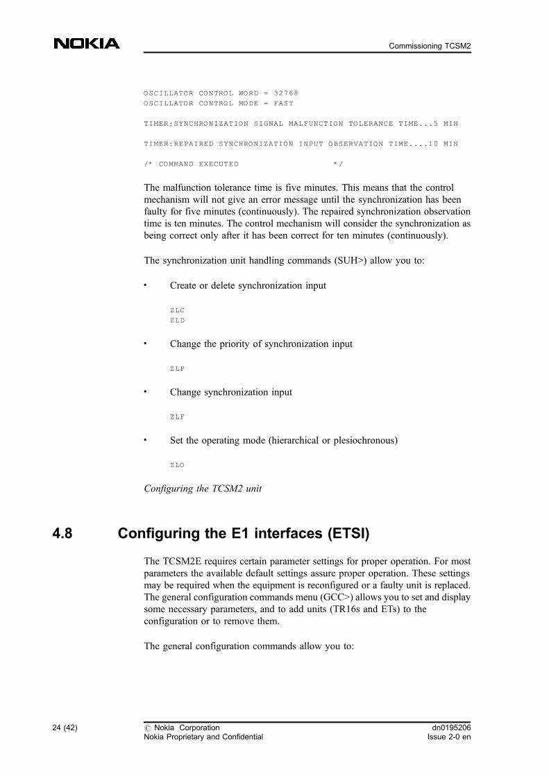
OSCILLATOR CONTROL WORD = 32768
OSCILLATOR CONTROL MODE = FAST
TIMER:SYNCHRONIZATION SIGNAL MALFUNCTION TOLERANCE TIME...5 MIN
TIMER:REPAIRED SYNCHRONIZATION INPUT OBSERVATION TIME....10 MIN
/* COMMAND EXECUTED */
The malfunction tolerance time is five minutes. This means that the controlmechanism will not give an error message until the synchronization has beenfaulty for five minutes (continuously). The repaired synchronization observationtime is ten minutes. The control mechanism will consider the synchronization asbeing correct only after it has been correct for ten minutes (continuously).
The synchronization unit handling commands (SUH>) allow you to:
. Create or delete synchronization input
ZLC
ZLD
. Change the priority of synchronization input
ZLP
. Change synchronization input
ZLF
. Set the operating mode (hierarchical or plesiochronous)
ZLO
Configuring the TCSM2 unit
4.8 Configuring the E1 interfaces (ETSI)
The TCSM2E requires certain parameter settings for proper operation. For mostparameters the available default settings assure proper operation. These settingsmay be required when the equipment is reconfigured or a faulty unit is replaced.The general configuration commands menu (GCC>) allows you to set and displaysome necessary parameters, and to add units (TR16s and ETs) to theconfiguration or to remove them.
The general configuration commands allow you to:
24 (42) # Nokia CorporationNokia Proprietary and Confidential
dn0195206Issue 2-0 en
Commissioning TCSM2
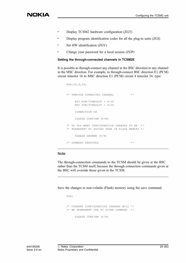
. Display TCSM2 hardware configuration (ZGT)
. Display program identification codes for all the plug-in units (ZGI)
. Set HW identification (ZGV)
. Change your password for a local session (ZGP)
Setting the through-connected channels in TCSM2E
It is possible to through-connect any channel in the BSC direction to any channelin the MSC direction. For example, to through-connect BSC direction E1 (PCM)circuit timeslot 16 to MSC direction E1 (PCM) circuit 4 timeslot 24, type:
ZGH:16,4,24;
/* THROUGH CONNECTED CHANNEL */
BSC PCM-TIMESLOT = 0-16
MSC PCM-TIMESLOT = 4-24
CONNECTION ON
PLEASE CONFIRM (Y/N)
/* DO YOU WANT CONFIGURATION CHANGES TO BE */
/* PERMANENT BY SAVING THEM IN FLASH MEMORY */
PLEASE ANSWER (Y/N)
/* COMMAND EXECUTED */
Note
The through-connection commands to the TCSM should be given at the BSCrather than the TCSM itself, because the through-connection commands given atthe BSC will override those given at the TCSM.
Save the changes to non-volatile (Flash) memory using the save command.
ZGS;
/* CURRENT CONFIGURATION CHANGES WILL */
/* BE PERMANENT DUE TO GIVEN COMMAND */
PLEASE CONFIRM (Y/N)
dn0195206Issue 2-0 en
# Nokia CorporationNokia Proprietary and Confidential
25 (42)
Configuring the TCSM2 unit
/* COMMAND EXECUTED */
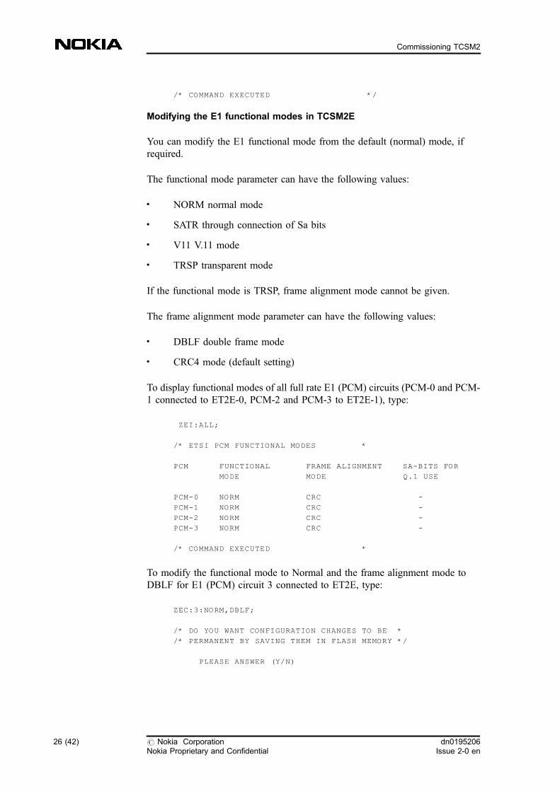
Modifying the E1 functional modes in TCSM2E
You can modify the E1 functional mode from the default (normal) mode, ifrequired.
The functional mode parameter can have the following values:
. NORM normal mode
. SATR through connection of Sa bits
. V11 V.11 mode
. TRSP transparent mode
If the functional mode is TRSP, frame alignment mode cannot be given.
The frame alignment mode parameter can have the following values:
. DBLF double frame mode
. CRC4 mode (default setting)
To display functional modes of all full rate E1 (PCM) circuits (PCM-0 and PCM-1 connected to ET2E-0, PCM-2 and PCM-3 to ET2E-1), type:
ZEI:ALL;
/* ETSI PCM FUNCTIONAL MODES *
PCM FUNCTIONAL FRAME ALIGNMENT SA-BITS FOR
MODE MODE Q.1 USE
PCM-0 NORM CRC -
PCM-1 NORM CRC -
PCM-2 NORM CRC -
PCM-3 NORM CRC -
/* COMMAND EXECUTED *
To modify the functional mode to Normal and the frame alignment mode toDBLF for E1 (PCM) circuit 3 connected to ET2E, type:
ZEC:3:NORM,DBLF;
/* DO YOU WANT CONFIGURATION CHANGES TO BE *
/* PERMANENT BY SAVING THEM IN FLASH MEMORY */
PLEASE ANSWER (Y/N)
26 (42) # Nokia CorporationNokia Proprietary and Confidential
dn0195206Issue 2-0 en
Commissioning TCSM2
/* COMMAND EXECUTED */
CRC setting:
The default functional mode activates the CRC, and if there are alarms due toremote end incompatibility, the CRC should be cancelled. The only way to cancelit is to choose the DBLF setting for frame alignment mode.
Note
After the program loading of the ETs, the program settings override the jumpersettings.
Configuring the TCSM2 unit
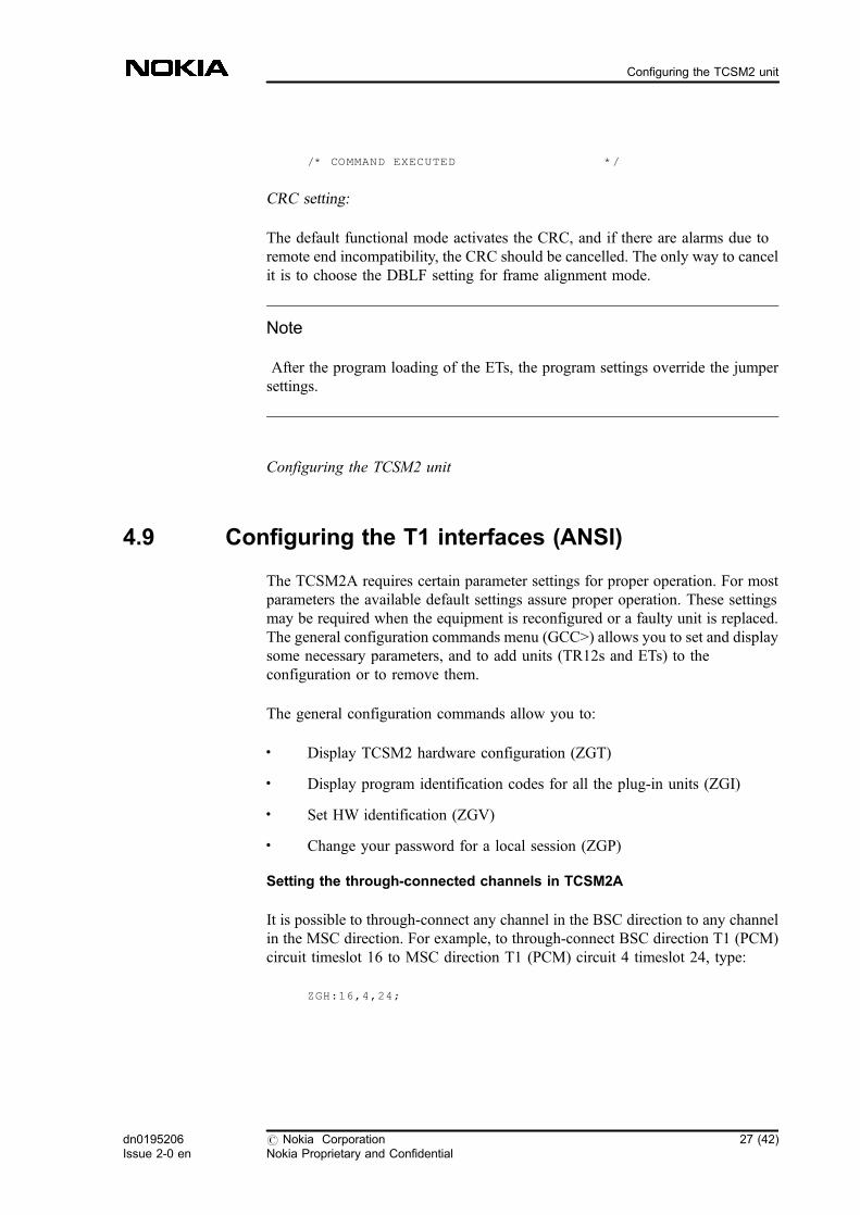
4.9 Configuring the T1 interfaces (ANSI)
The TCSM2A requires certain parameter settings for proper operation. For mostparameters the available default settings assure proper operation. These settingsmay be required when the equipment is reconfigured or a faulty unit is replaced.The general configuration commands menu (GCC>) allows you to set and displaysome necessary parameters, and to add units (TR12s and ETs) to theconfiguration or to remove them.
The general configuration commands allow you to:
. Display TCSM2 hardware configuration (ZGT)
. Display program identification codes for all the plug-in units (ZGI)
. Set HW identification (ZGV)
. Change your password for a local session (ZGP)
Setting the through-connected channels in TCSM2A
It is possible to through-connect any channel in the BSC direction to any channelin the MSC direction. For example, to through-connect BSC direction T1 (PCM)circuit timeslot 16 to MSC direction T1 (PCM) circuit 4 timeslot 24, type:
ZGH:16,4,24;
dn0195206Issue 2-0 en
# Nokia CorporationNokia Proprietary and Confidential
27 (42)
Configuring the TCSM2 unit
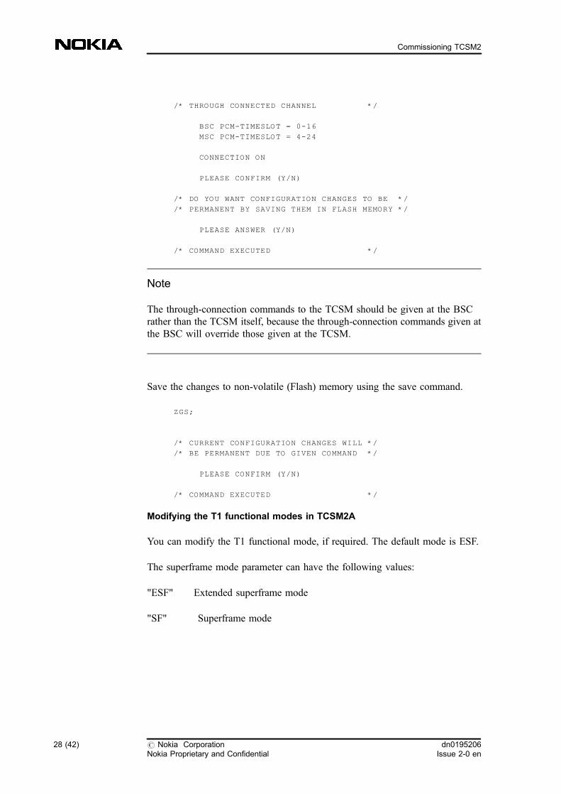
/* THROUGH CONNECTED CHANNEL */
BSC PCM-TIMESLOT = 0-16
MSC PCM-TIMESLOT = 4-24
CONNECTION ON
PLEASE CONFIRM (Y/N)
/* DO YOU WANT CONFIGURATION CHANGES TO BE */
/* PERMANENT BY SAVING THEM IN FLASH MEMORY */
PLEASE ANSWER (Y/N)
/* COMMAND EXECUTED */
Note
The through-connection commands to the TCSM should be given at the BSCrather than the TCSM itself, because the through-connection commands given atthe BSC will override those given at the TCSM.
Save the changes to non-volatile (Flash) memory using the save command.
ZGS;
/* CURRENT CONFIGURATION CHANGES WILL */
/* BE PERMANENT DUE TO GIVEN COMMAND */
PLEASE CONFIRM (Y/N)
/* COMMAND EXECUTED */
Modifying the T1 functional modes in TCSM2A
You can modify the T1 functional mode, if required. The default mode is ESF.
The superframe mode parameter can have the following values:
"ESF" Extended superframe mode
"SF" Superframe mode
28 (42) # Nokia CorporationNokia Proprietary and Confidential
dn0195206Issue 2-0 en
Commissioning TCSM2
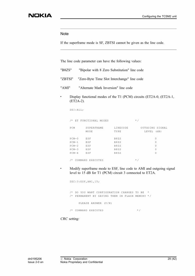
Note
If the superframe mode is SF, ZBTSI cannot be given as the line code.
The line code parameter can have the following values:
"B8ZS" "Bipolar with 8 Zero Substitution" line code
"ZBTSI" "Zero-Byte Time Slot Interchange" line code
"AMI" "Alternate Mark Inversion" line code
. Display functional modes of the T1 (PCM) circuits (ET2A-0, (ET2A-1,(ET2A-2).
ZEI:ALL;
/* ET FUNCTIONAL MODES */
PCM SUPERFRAME LINECODE OUTGOING SIGNAL
MODE TYPE LEVEL (dB)
PCM-0 ESF B8ZS 0
PCM-1 ESF B8ZS 0
PCM-2 ESF B8ZS 0
PCM-3 ESF B8ZS 0
PCM-4 ESF B8ZS 0
/* COMMAND EXECUTED */
. Modify superframe mode to ESF, line code to AMI and outgoing signallevel to 15 dB for T1 (PCM) circuit 3 connected to ET2A.
ZEC:3:ESF,AMI,15;
/* DO YOU WANT CONFIGURATION CHANGES TO BE *
/* PERMANENT BY SAVING THEM IN FLASH MEMORY */
PLEASE ANSWER (Y/N)
/* COMMAND EXECUTED */
CRC setting:
dn0195206Issue 2-0 en
# Nokia CorporationNokia Proprietary and Confidential
29 (42)
Configuring the TCSM2 unit
Note that the default functional mode (ESF) sets the CRC in use, and if there arealarms due to remote end incompatibility, the CRC should be cancelled. The onlyway to cancel it is to choose another setting for functional mode, which is SF.
Configuring the TCSM2 unit
4.10 Other transcoder configuration procedures (ETSI,ANSI)
The Transcoder Configuration Commands allow you to set transcoder-specificparameters.
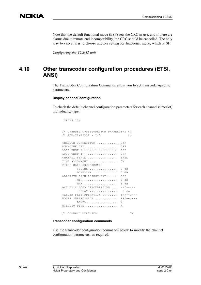
Display channel configuration
To check the default channel configuration parameters for each channel (timeslot)individually, type:
ZRC:3,12;
/* CHANNEL CONFIGURATION PARAMETERS */
/* PCM-TIMESLOT = 2-1 */
THROUGH CONNECTION ............ OFF
DOWNLINK DTX ................. OFF
LOOP TEST 0 .................. OFF
LOOP TEST 1 .................. OFF
CHANNEL STATE ................ FREE
TIME ALIGNMENT ............... ON
FIXED GAIN ADJUSTMENT
UPLINK ............... 0 dB
DOWNLINK ............. 0 dB
ADAPTIVE GAIN ADJUSTMENT...... OFF
MIN .................. 0 dB
MAX .................. 6 dB
ACOUSTIC ECHO CANCELLATION ... --/--/--
DELAY ............... 0 ms
TANDEM FREE OPERATION ........ FR/--/---
NOISE SUPPRESSION ............ FR/--/---
LEVEL ................ 2
CIRCUIT TYPE ................. A
/* COMMAND EXECUTED */
Transcoder configuration commands
Use the transcoder configuration commands below to modify the channelconfiguration parameters, as required:
30 (42) # Nokia CorporationNokia Proprietary and Confidential
dn0195206Issue 2-0 en
Commissioning TCSM2
. Set downlink DTX (ZRX). This setting is only for testing purposes and itshould always be set OFF.
. Set adaptive gain adjustment in downlink direction (ZRA). Set whenrequired.
. Set fixed gain adjustment for uplink and downlink (ZRF). Set whenrequired.
. Set time alignment (ZRS). This is usually set on, but if the Abis linkinvolves a satellite link it should be set off.
. Start traffic channel monitoring (ZRM).
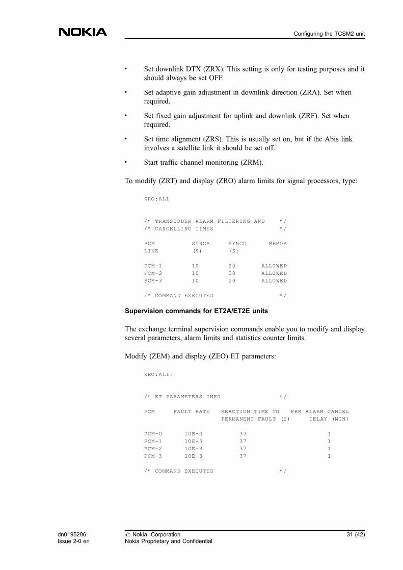
To modify (ZRT) and display (ZRO) alarm limits for signal processors, type:
ZRO:ALL
/* TRANSCODER ALARM FILTERING AND */
/* CANCELLING TIMES */
PCM SYNCA SYNCC MEMOA
LINE (S) (S)
PCM-1 10 20 ALLOWED
PCM-2 10 20 ALLOWED
PCM-3 10 20 ALLOWED
/* COMMAND EXECUTED */
Supervision commands for ET2A/ET2E units
The exchange terminal supervision commands enable you to modify and displayseveral parameters, alarm limits and statistics counter limits.
Modify (ZEM) and display (ZEO) ET parameters:
ZEO:ALL;
/* ET PARAMETERS INFO */
PCM FAULT RATE REACTION TIME TO FRM ALARM CANCEL
PERMANENT FAULT (S) DELAY (MIN)
PCM-0 10E-3 37 1
PCM-1 10E-3 37 1
PCM-2 10E-3 37 1
PCM-3 10E-3 37 1
/* COMMAND EXECUTED */
dn0195206Issue 2-0 en
# Nokia CorporationNokia Proprietary and Confidential
31 (42)
Configuring the TCSM2 unit
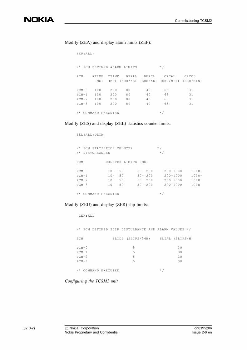
Modify (ZEA) and display alarm limits (ZEP):
ZEP:ALL;
/* PCM DEFINED ALARM LIMITS */
PCM ATIME CTIME BERAL BERCL CRCAL CRCCL
(MS) (MS) (ERR/5S) (ERR/5S) (ERR/MIN) (ERR/MIN)
PCM-0 100 200 80 40 63 31
PCM-1 100 200 80 40 63 31
PCM-2 100 200 80 40 63 31
PCM-3 100 200 80 40 63 31
/* COMMAND EXECUTED */
Modify (ZES) and display (ZEL) statistics counter limits:
ZEL:ALL:DLIM
/* PCM STATISTICS COUNTER */
/* DISTURBANCES */
PCM COUNTER LIMITS (MS)
PCM-0 10- 50 50- 200 200-1000 1000-
PCM-1 10- 50 50- 200 200-1000 1000-
PCM-2 10- 50 50- 200 200-1000 1000-
PCM-3 10- 50 50- 200 200-1000 1000-
/* COMMAND EXECUTED */
Modify (ZEU) and display (ZER) slip limits:
ZER:ALL
/* PCM DEFINED SLIP DISTURBANCE AND ALARM VALUES */
PCM SLIDL (SLIPS/24H) SLIAL (SLIPS/H)
PCM-0 5 30
PCM-1 5 30
PCM-2 5 30
PCM-3 5 30
/* COMMAND EXECUTED */
Configuring the TCSM2 unit
32 (42) # Nokia CorporationNokia Proprietary and Confidential
dn0195206Issue 2-0 en
Commissioning TCSM2
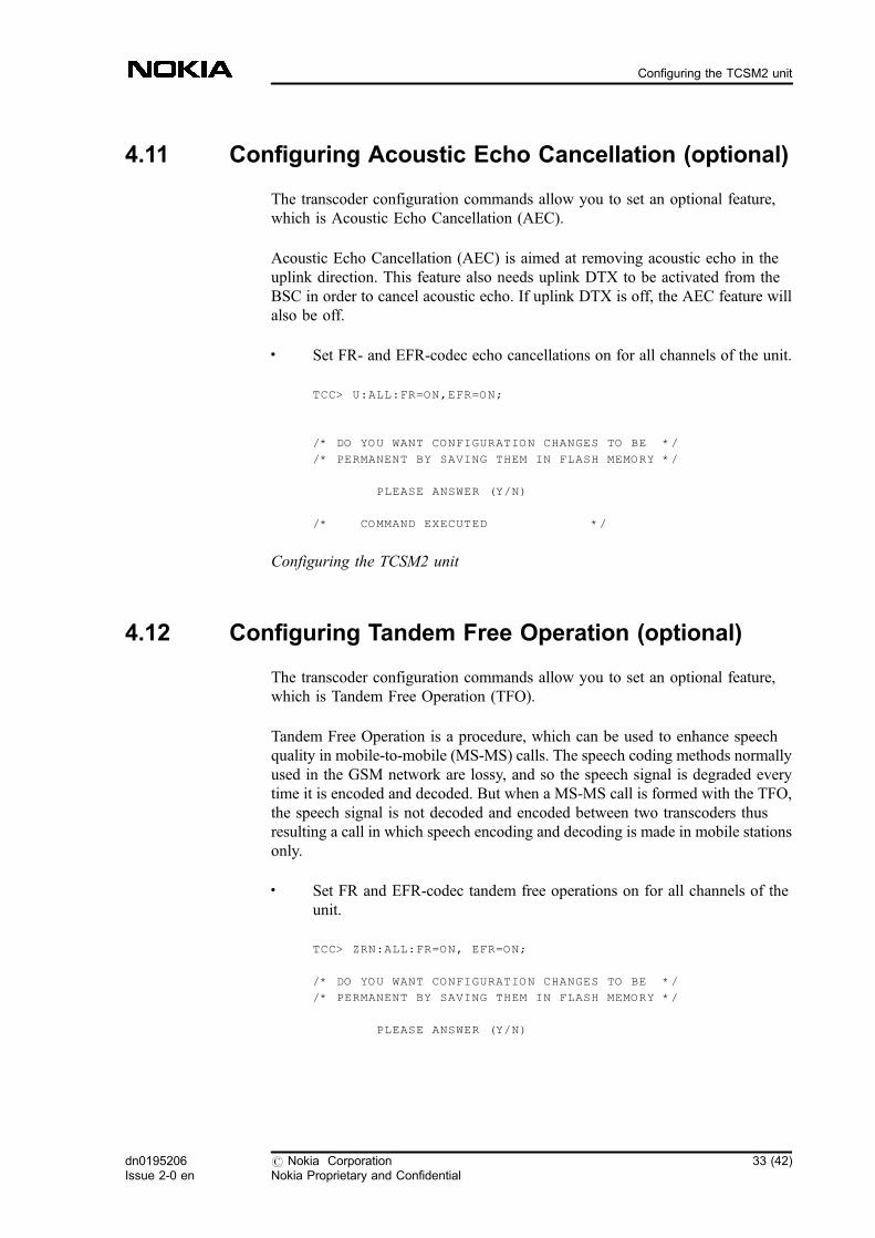
4.11 Configuring Acoustic Echo Cancellation (optional)
The transcoder configuration commands allow you to set an optional feature,which is Acoustic Echo Cancellation (AEC).
Acoustic Echo Cancellation (AEC) is aimed at removing acoustic echo in theuplink direction. This feature also needs uplink DTX to be activated from theBSC in order to cancel acoustic echo. If uplink DTX is off, the AEC feature willalso be off.
. Set FR- and EFR-codec echo cancellations on for all channels of the unit.
TCC> U:ALL:FR=ON,EFR=ON;
/* DO YOU WANT CONFIGURATION CHANGES TO BE */
/* PERMANENT BY SAVING THEM IN FLASH MEMORY */
PLEASE ANSWER (Y/N)
/* COMMAND EXECUTED */
Configuring the TCSM2 unit
4.12 Configuring Tandem Free Operation (optional)
The transcoder configuration commands allow you to set an optional feature,which is Tandem Free Operation (TFO).
Tandem Free Operation is a procedure, which can be used to enhance speechquality in mobile-to-mobile (MS-MS) calls. The speech coding methods normallyused in the GSM network are lossy, and so the speech signal is degraded everytime it is encoded and decoded. But when a MS-MS call is formed with the TFO,the speech signal is not decoded and encoded between two transcoders thusresulting a call in which speech encoding and decoding is made in mobile stationsonly.
. Set FR and EFR-codec tandem free operations on for all channels of theunit.
TCC> ZRN:ALL:FR=ON, EFR=ON;
/* DO YOU WANT CONFIGURATION CHANGES TO BE */
/* PERMANENT BY SAVING THEM IN FLASH MEMORY */
PLEASE ANSWER (Y/N)
dn0195206Issue 2-0 en
# Nokia CorporationNokia Proprietary and Confidential
33 (42)
Configuring the TCSM2 unit

/* COMMAND EXECUTED */
Configuring the TCSM2 unit
4.13 Configuring Noise Suppression (optional)
The transcoder configuration commands allow you to set an optional feature,which is Noise Suppression (NS).
NS is a procedure, which is used to reduce background noise level during speechcalls. When activated, the noise suppression algorithm (ALWE) processes theuplink and downlink speech samples in order to reduce noise. The algorithmestimates background noise power spectrum based on input speech samples andvoice activity detection. The speech signal spectrum is then modified based onthe estimate and additional constraints. This procedure can be activated separatelyfor each speech codec (FR/HR/EFR) and transmission direction (uplink/downlink) using TCSM2 MMI.
Note
NS cannot be used with Text Telephony (TTY) in ANSI environment.
. Set FR and EFR-codec noise suppression on for all channels of the unit.
TCC> ZRY:ALL:FR=ON, EFR=ON;
/* DO YOU WANT CONFIGURATION CHANGES TO BE */
/* PERMANENT BY SAVING THEM IN FLASH MEMORY */
PLEASE ANSWER (Y/N)
/* COMMAND EXECUTED */
Configuring the TCSM2 unit
34 (42) # Nokia CorporationNokia Proprietary and Confidential
dn0195206Issue 2-0 en
Commissioning TCSM2
4.14 Alarm handling
Wired alarm handling
The wired alarm handling command allows you to display the current status of allthe wired alarms (ZAW) and to turn on or off the wired alarms from otherTCSM2 units.
To set the wired alarms of other TCSM2 units on:
ZAW:ON;
/* DO YOU WANT CONFIGURATION CHANGES TO BE */
/* PERMANENT BY SAVING THEM IN FLASH MEMORY */
PLEASE ANSWER (Y/N)
/* COMMAND EXECUTED */
Far-end alarm handling (ETSI)
Command F is used to set the TCSM2E behaviour when a far-end alarm isreceived in the BSC direction PCM circuit. TCSM2 can send an AIS or a far endalarm to the MSC. The type of this alarm to be sent to the MSC is given as aparameter. If no parameter is given the current state of far-end alarm handling isdisplayed. The alarms are listed below:
2902 PCM LINE REMOTE END ALARM
2900 INCOMING SIGNAL MISSING
2909 AIS RECEIVED
2925 SLIP FREQUENCY LIMIT EXCEEDED
2910 FRAMING ERROR
2912 BIT ERROR RATE OVER LIMIT
The parameter's value indicates which alarm is sent to the MSC.
OFF far end alarm or AIS not sent to MSC.
FEA far end alarm sent to MSC.
AIS AIS alarm sent to MSC.
dn0195206Issue 2-0 en
# Nokia CorporationNokia Proprietary and Confidential
35 (42)
Configuring the TCSM2 unit
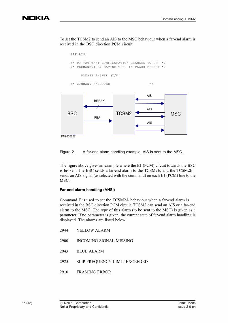
To set the TCSM2 to send an AIS to the MSC behaviour when a far-end alarm isreceived in the BSC direction PCM circuit.
ZAF:AIS;
/* DO YOU WANT CONFIGURATION CHANGES TO BE */
/* PERMANENT BY SAVING THEM IN FLASH MEMORY */
PLEASE ANSWER (Y/N)
/* COMMAND EXECUTED */
Figure 2. A far-end alarm handling example, AIS is sent to the MSC.
The figure above gives an example where the E1 (PCM) circuit towards the BSCis broken. The BSC sends a far-end alarm to the TCSM2E, and the TCSM2Esends an AIS signal (as selected with the command) on each E1 (PCM) line to theMSC.
Far-end alarm handling (ANSI)
Command F is used to set the TCSM2A behaviour when a far-end alarm isreceived in the BSC direction PCM circuit. TCSM2 can send an AIS or a far-endalarm to the MSC. The type of this alarm (to be sent to the MSC) is given as aparameter. If no parameter is given, the current state of far-end alarm handling isdisplayed. The alarms are listed below.
2944 YELLOWALARM
2900 INCOMING SIGNAL MISSING
2943 BLUE ALARM
2925 SLIP FREQUENCY LIMIT EXCEEDED
2910 FRAMING ERROR
BSC TCSM2 MSC
BREAK
AIS
AIS
AIS
FEA
DN9833207
36 (42) # Nokia CorporationNokia Proprietary and Confidential
dn0195206Issue 2-0 en
Commissioning TCSM2
2912 BIT ERROR RATE OVER LIMIT
The parameter's value indicates which alarm is sent to the MSC:
OFF far end alarm or AIS not sent to MSC.
FEA far end alarm sent to MSC.
AIS AIS alarm sent to MSC.
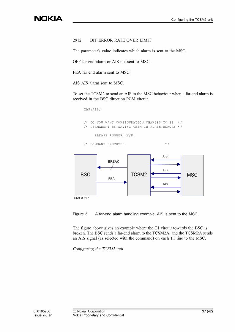
To set the TCSM2 to send an AIS to the MSC behaviour when a far-end alarm isreceived in the BSC direction PCM circuit.
ZAF:AIS;
/* DO YOU WANT CONFIGURATION CHANGES TO BE */
/* PERMANENT BY SAVING THEM IN FLASH MEMORY */
PLEASE ANSWER (Y/N)
/* COMMAND EXECUTED */
Figure 3. A far-end alarm handling example, AIS is sent to the MSC.
The figure above gives an example where the T1 circuit towards the BSC isbroken. The BSC sends a far-end alarm to the TCSM2A, and the TCSM2A sendsan AIS signal (as selected with the command) on each T1 line to the MSC.
Configuring the TCSM2 unit
BSC TCSM2 MSC
BREAK
AIS
AIS
AIS
FEA
DN9833207
dn0195206Issue 2-0 en
# Nokia CorporationNokia Proprietary and Confidential
37 (42)
Configuring the TCSM2 unit

4.15 Saving the configuration
Save the configuration changes to non-volatile (Flash) memory using the saveconfiguration command.
The local application program reads the configuration data of the plug-in unitsfrom RAM memory and saves them to non-volatile memory. The localapplication program prompts for confirmation before performing the operation:
ZGS;
/* CURRENT CONFIGURATION CHANGES WILL */
/* BE PERMANENT DUE TO GIVEN COMMAND */
PLEASE CONFIRM (Y/N)
/* COMMAND EXECUTED *
Configuring the TCSM2 unit
38 (42) # Nokia CorporationNokia Proprietary and Confidential
dn0195206Issue 2-0 en
Commissioning TCSM2
5 Testing the TCSM2 unit configurations
The commissioning is divided into the following subtasks:
. local diagnostics
. traffic channels of the TCSM2
Commissioning TCSM2
5.1 Running the diagnostics tests
Local diagnostics
When the configuration procedure is completed, you should test the entireTCSM2A unit. This diagnostics procedure tests the:
. TRCO plug-in unit
. memory (RAM, FLASH)
. clock
. timer service
. HDLC controller loop
. ET diagnostics
A loop test 1 is also performed, in which each transcoder sends data in the BSCand MSC directions, and the transmitted data is compared with the data loopedback by the ET plug-in units.
To perform local diagnostics, first make sure that the PC is connected to the localterminal interface on the front panel of the TRCO plug-in unit.
To start the diagnostics for the TCSM2 unit, give the command:
ZCC:TOTAL;
dn0195206Issue 2-0 en
# Nokia CorporationNokia Proprietary and Confidential
39 (42)
Testing the TCSM2 unit configurations

/* ALL CALLS WILL BE CANCELLED DUE */
/* TO GIVEN COMMAND */
PLEASE CONFIRM (Y/N)
/* COMMAND EXECUTED */
Display the results of the latest test (the complete diagnostics test) by giving thecommand:
ZCO;
/* DIAGNOSTICS RESULTS */
RAM TEST OK
FLASH TEST OK
WATCHDOG TEST OK
CLOCK TEST OK
HDLC CONTROLLER TEST OK
FOR LAPD CHANNEL 1 2 3 4
OK OK OK OK
LOOP TEST-1 OK
/* COMMAND EXECUTED */
If the E1/T1 lines are live and connected to the MSC and BSC, no alarms shouldbe visible on your PC. If any alarms appear, excluding alarm number 2951 (localuser logged in), take the appropriate action to clear the alarm situations.
The selftest of the TCSM2 involves a fairly comprehensive test of each plug-inunit handling individual traffic channels. If a persistent fault is present in theindividual channels, the respective plug-in unit should be replaced.
Remote diagnostics from the BSC
You can also run the diagnostics test from the BSC using the command: ZUDU:TCSM,index.
Testing the alarm system ofthe TCSM2
This test can be done when the BSC and its connection(s) are already presumed tobe working, to verify that the basic alarm mechanism is functional up to the BSC(see the figure below).
40 (42) # Nokia CorporationNokia Proprietary and Confidential
dn0195206Issue 2-0 en
Commissioning TCSM2
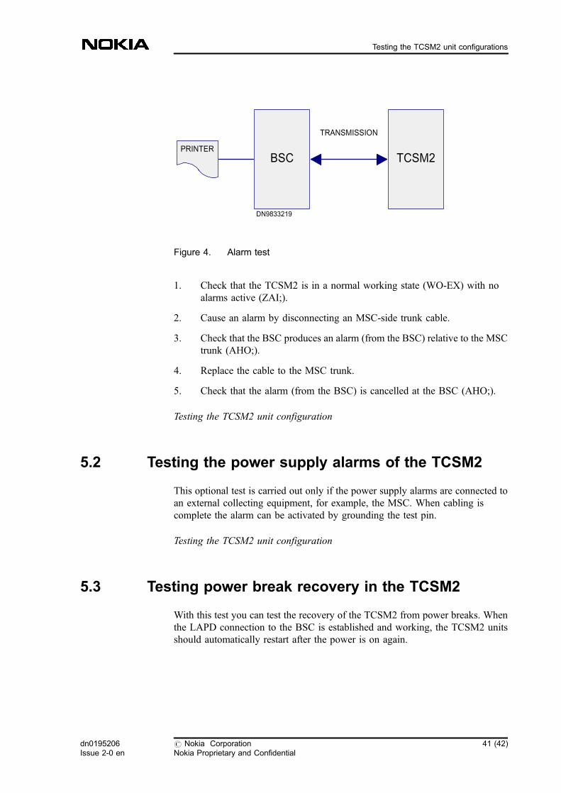
Figure 4. Alarm test
1. Check that the TCSM2 is in a normal working state (WO-EX) with noalarms active (ZAI;).
2. Cause an alarm by disconnecting an MSC-side trunk cable.
3. Check that the BSC produces an alarm (from the BSC) relative to the MSCtrunk (AHO;).
4. Replace the cable to the MSC trunk.
5. Check that the alarm (from the BSC) is cancelled at the BSC (AHO;).
Testing the TCSM2 unit configuration
5.2 Testing the power supply alarms of the TCSM2
This optional test is carried out only if the power supply alarms are connected toan external collecting equipment, for example, the MSC. When cabling iscomplete the alarm can be activated by grounding the test pin.
Testing the TCSM2 unit configuration
5.3 Testing power break recovery in the TCSM2
With this test you can test the recovery of the TCSM2 from power breaks. Whenthe LAPD connection to the BSC is established and working, the TCSM2 unitsshould automatically restart after the power is on again.
TRANSMISSION
BSC TCSM2
DN9833219
PRINTER
dn0195206Issue 2-0 en
# Nokia CorporationNokia Proprietary and Confidential
41 (42)
Testing the TCSM2 unit configurations

1. Check that the TCSM2 is in a normal state with no alarms active and thepower supplies on (ZAI;).
2. Disconnect the power from the TCSM2 rack by flicking the two powerswitches to the OFF position on the PSA-0 or PSA-1 front panel. The evenor odd numbered TCSM2 units should go off.
3. The BSC should produce the alarms (AHO;) indicating the loss ofconnection (2M signal missing).
4. Connect the power to the TCSM2 units back on by flicking the powerswitches to the ON position.
5. The TCSM2 units should recover automatically.
6. The BSC should cancel the current alarms (AHO;).
Testing the TCSM2 unit configuration
42 (42) # Nokia CorporationNokia Proprietary and Confidential
dn0195206Issue 2-0 en
Commissioning TCSM2


