79
Common Channel Signalling
| Date post: | 03-Jan-2016 |
| Category: |
Documents |
| Upload: | tyler-casey |
| View: | 221 times |
| Download: | 0 times |
Common Channel Signalling
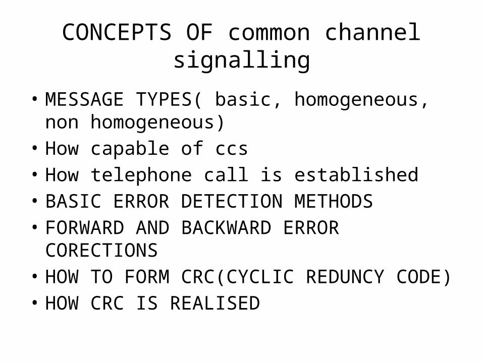
CONCEPTS OF common channel signalling
• MESSAGE TYPES( basic, homogeneous, non homogeneous)
• How capable of ccs• How telephone call is established• BASIC ERROR DETECTION METHODS• FORWARD AND BACKWARD ERROR CORECTIONS• HOW TO FORM CRC(CYCLIC REDUNCY CODE)• HOW CRC IS REALISED
MESSAGE TYPES
• BASIC MESSAGE
• HOMOGENIOUS MESSAGE
• NON HOMOGENEOUS MESSAGE

Basic Message
Message for Homogenous Network
= K1
= K2Instruction
DataLabelLabel
OPC DPC CIC
14bits 14bits 12bits
Instruction
Data
Fixed Variable
Instruction
Data
OPC – Originating Point Cord
DPC – Destination Point Cord
CIC – Circuit Identification Cord

WHY NOT?
SIO - Service Information OctelK2 - Message for Homogenous Network
Message for Non-Homogenous Network
SIO K2SIO K2Instruction
DataLabel
4bits4bits
National or
International Message
User
Part
Now we are ready with the complete message, can we transmit it just as it is?
NO
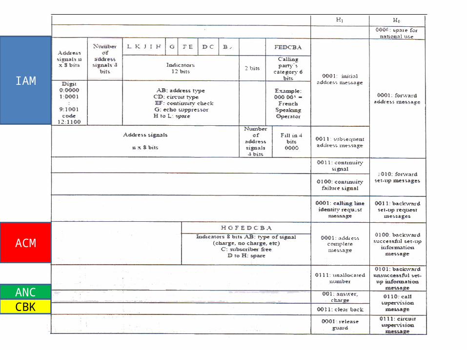
IAM
ACM
ANCCBK
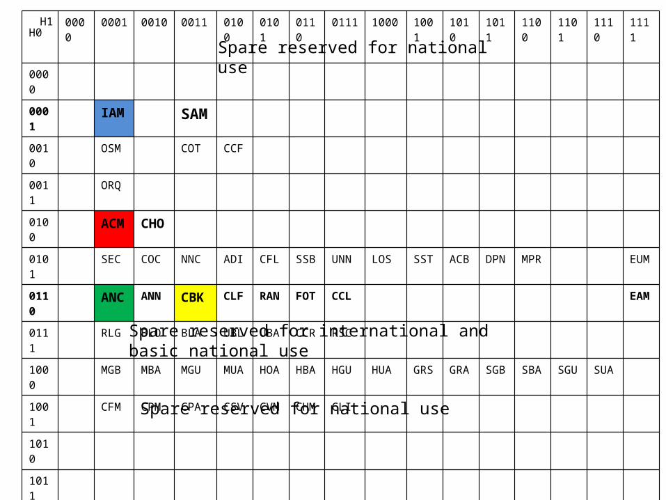
0000
0001 0010 0011 0100 0101 0110 0111 1000 1001 1010 1011 1100 1101 1110 1111
0000
0001 IAM SAM
0010 OSM COT CCF
0011 ORQ
0100 ACM CHO
0101 SEC COC NNC ADI CFL SSB UNN LOS SST ACB DPN MPR EUM
0110 ANC ANN CBK CLF RAN FOT CCL EAM
0111 RLG BLO BLA UBL UBA CCR RSC
1000 MGB MBA MGU MUA
HOA HBA HGU HUA GRS GRA SGB SBA SGU SUA
1001 CFM CPM CPA CSV CVM CHM CLI
1010
1011
1100
1101
1110
1111
H0H1
Spare reserved for international and basic national use
Spare reserved for national use
Spare reserved for national use
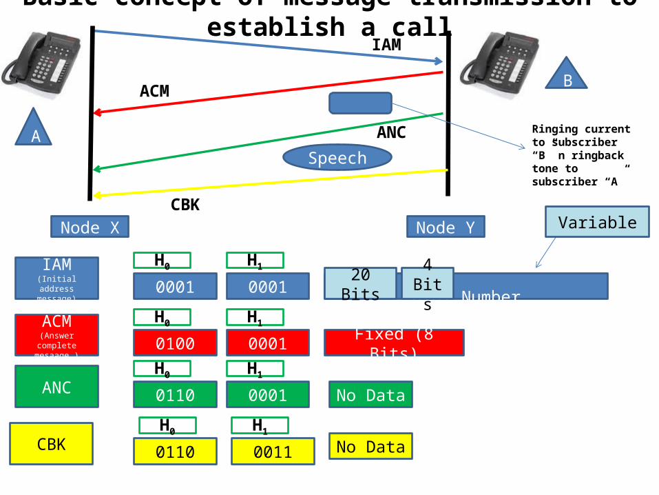
Basic concept of message transmission to establish a call
A
B
Node X Node Y
IAM
ACM
ANC
CBK
Speech
Ringing current to subscriber “B” n ringback tone to subscriber “A”
IAM(Initial address
message)
ACM(Answer complete
mesaage )
ANC
CBK
0001 0001 Dial Number
0100 0001
0110 0001
0110 0011
Fixed (8 Bits)
H0 H1
H0 H1
H0 H1
H0 H1
20 Bits 4 Bits
Variable
No Data
No Data

HOW THE COMMON CHANNEL SIGNALLING WORKS
• ASSUME A CALL IS ESTABLISHED IN A NETWORK WHERE THERE ARE TWO EXCHANGES(EX X & EX Y) ARE CONNECTED WITH 16 PCM SYSTEMS.
• THE CALL IS CONNECTED VIA CIRCUIT NUMBER 305. ASSUME P(0) TS16 & P1(1) IS USED FOR COMMON CHANNEL SIGNALLING.
• DRAW HOW THE SIGNALS ARE ESTABLISHED BETWEEN THE EXCHANGES(assume the call is establised, and after the call, A keeps the receiver first)
• Calculate the total times taken for forward & backward signalling

X
exchange
Y
exchange
P0f
P1f
P15f
P0b
P1b
P15b
Need to transfer message between A to B
Customer A Customer B

Helicopter ViewExchange X Exchange X
IAM
ACM
ANS
CBR
( P0f TS16 )
( P0b TS16 )
RBT( P9 TS28)
( P0b TS16 )
( P9b TS28)speaking( P9f TS28)
( P0f TS16 )
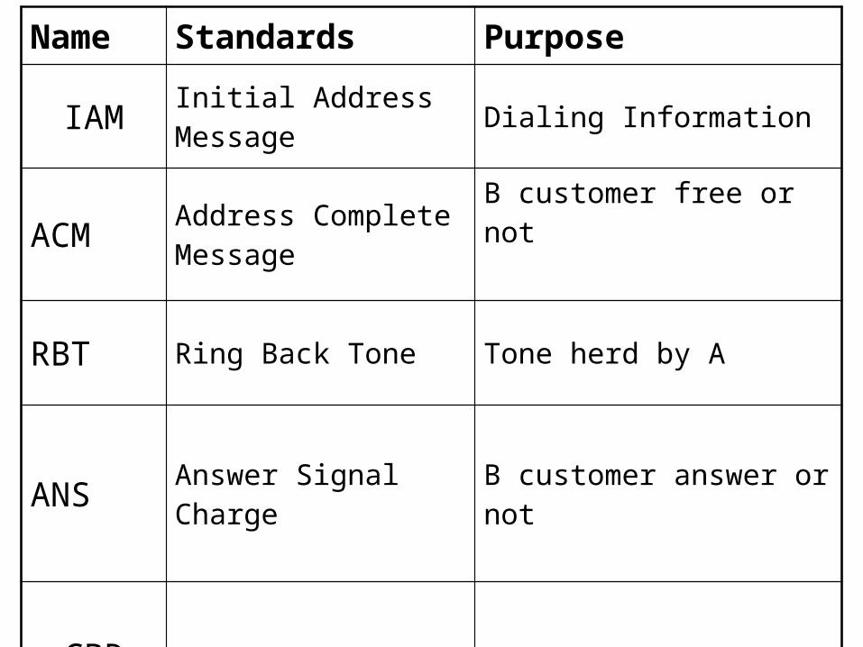
Name Standards Purpose
IAM Initial Address Message Dialing Information
ACM Address Complete Message
B customer free or not
RBT Ring Back Tone Tone herd by A
ANS Answer Signal Charge B customer answer or not
CBR Call Back Tone Release the circuit

CALCULATION !

Number of voice channel for voice communication between X and Y
Channel number that we use
If we numbered voice channel from 1 to 494 : - Select related TS 30 + 30 =60 305 – 60 = 245 245 / 31 = 7 mod 28
P9 TS28 (PCM no = 9 , TS no = 28)
= (31 * 14) + (30 *2) 494
= 305
7 + 2 = 9

Number that we dial = 15904607
0001 0001 0011 1000,1010,1001,0000,1000,1100,0000,1110
IAM
4 bits 4 bits 8 4 4 bits 4 * 8 bits
K=56 bits
CRC SCF SIO 1 2 305 K
Message
16 bits
16 bits
8 bits
12bits
12bits
14bits
56bits8 bits
8 bits
Total bits = 150

ACM0001 0110
4 bits 4 bits 8 bits
Message
CRC SCF SIO 1 2 305 K
16bits
16 bits
8 bits
12bits
12bits
14bits
16bits
8bits
8bits
Total bits = 110
K=16 bits

ANC0001 0110
4 bits 4 bits
Message
CRC SCF SIO 1 2 305 K
16bits
16 bits
8 bits
12bits
12bits
14bits
8bits
8bits
8bits
Total bits = 102
K=8 bits

CBR0001 0110
4 bits 4 bits
Message
CRC SCF SIO 1 2 305 K
16bits
16 bits
8 bits
12bits
12bits
14bits
8bits
8bits
8bits
Total bits = 102
K=8 bits
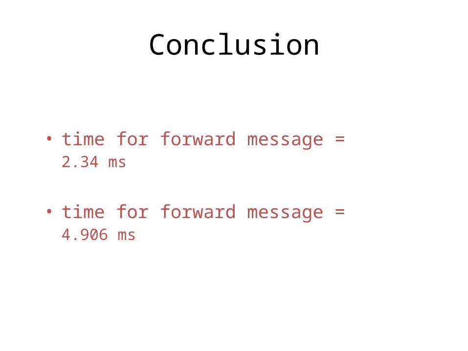
Conclusion
• time for forward message = 2.34 ms
• time for forward message = 4.906 ms
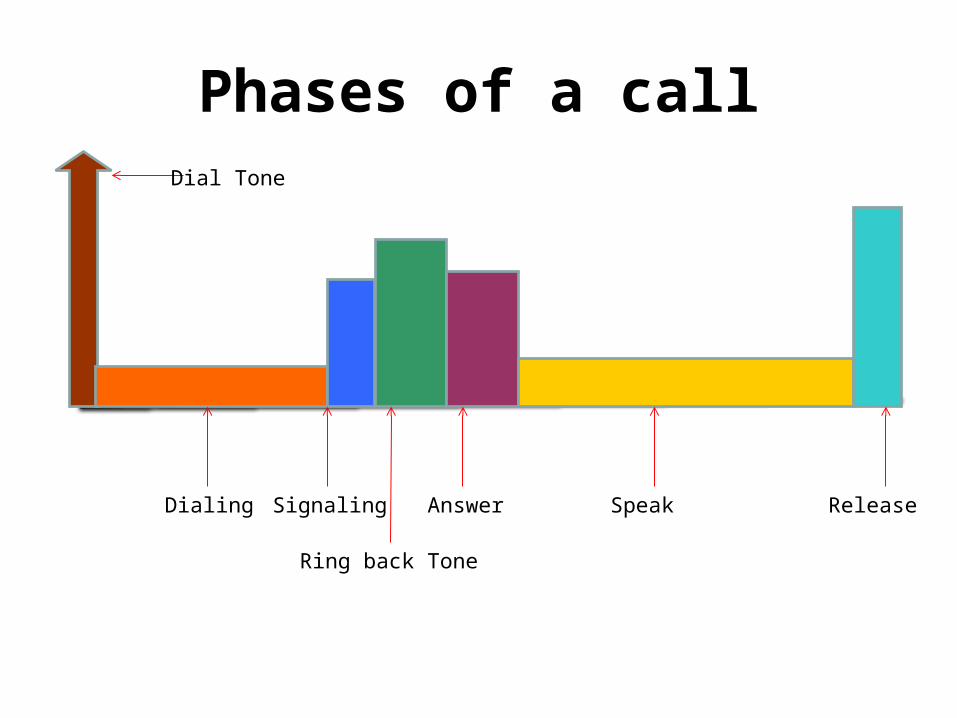
Phases of a callDial Tone
Dialing Signaling
Ring back Tone
Answer Speak Release

ERROR CONTROL
• FORWARD ERROR CORRECTION• Detect and correct the error• In unidirectional transmission
• BACKWARD ERROR CORRECTION• Detect the error and request for
retransmission• In bydirectional transmission

CYCLIC REDUNCY CODE OR FRAME CHECH SEQUANCE
• DESIGNED TO DETECT NOISE BURST• ACCORDING TO THE NOISE CHARACTERISTICS A
POLYNOMIAL IS IDENTIFIED(N+1 BITS)• SHIFT THE MESSAGE BY N BITS• THEN DIVIDE BY MOULO 2 THE SHIFTED MESSAGE BY THE
POLYNOMIAL• GET THE RESIDUAL OF N BITS & SHIFT THE MESSAGE BY
THESE BITS AS CRC• AT THE RECEIVER IF THERE ARE NO ERRORS, YOU WILL NOT
GET ANY RESIDUAL WHEN YOU DIVIDE THE RECIEVED MESSAGE BY THE SAME POLYNOMIAL
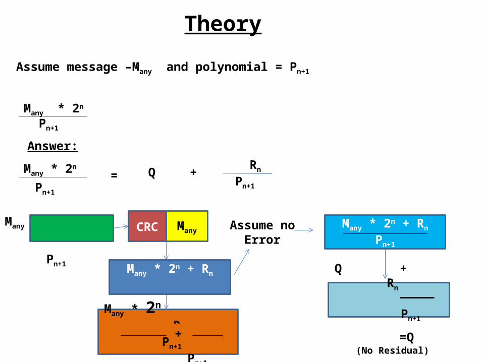
Theory
Assume message –Many and polynomial = Pn+1
Many * 2n
Answer:
Many * 2n
= Q +
Rn
Pn+1
Pn+1
Pn+1
CRC ManyMany
Pn+1
Assume no Error
Many * 2n + Rn
Pn+1
=Q(No Residual)
Many * 2n + Rn
Many * 2n Rn
Pn+1 Pn+1
+
Q + Rn
Pn+1

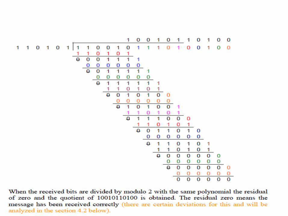
EXAMPLE ON CRC

In order to formulate the CRC the message of 11 bits (assume) has been shifted by 5 bits and the total modified message has been divided in modulo 2 division by the polynomial which is shown below
1 1 0 0 1 0 1 1 0 1 0 0 0 01 1 0 1 0 1
1
0 0 0 1 1 1 10 0 0 0 0 00 0 1 1 1 1 1
0 0 0 0 0 0
0 1 1 1 11 11 1 0 1 0 1
0 0 1 0 01 00 0 0 0 0 0
0 1 0 1 0 0 11 1 0 1 0 1
0 1 1 1 0 0 01 1 0 1 0 1
0 0 1 1 0 010 0 0 0 0 0
0 1 1 0 1 0 01 1 0 1 0 1
0 0 0 0 0 1 00 0 0 0 0 0
0
0 0 0 0 1 0 00 0 0 0 0 00 0 0 1 0 0
1 0 0 1 0 1 1 0 1 0 0
1 1 0 1 0 1
You will see the residual
as 00100 and the quotient is
100101101
Hence transmit word:
11001011101 : 00100


Understanding cyclic redundancy code of error correction(Question)


Hence there are no errors

Hint to answer
• Write the polynomial in x• Draw the 1 bit shift registers and the circuit diagram• Write the timing equations for n+1 th step for each
output• Sketh the output map– no of columns=no of
outputs+steps+input(pl add to the message the no of zeros or crc depending upon the situation, no of rows has to be input+2
• Carryout the timing equation for each step, the last step will give you the output

CRC• Polynomial:P=11001,P(x)=x4+x3+x0
• X4 X3 X2 X1 X0
• Timing equations
• An + In = Dn+1
• Dn = Cn+1
• Cn = Bn+1
• An + Bn = An+1
+ +A B C D
Input Data
I
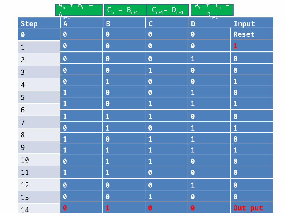
Step A B C D Input
0
1
2
3
4
5
6
7
8
9
10
11
12
13
1415
0 0 0 0 Reset
0 0 0 0 1
0 0 0 1 0
0 0 1 0 0
0 1 0 0 1
1 0 0 1 0
1 0 1 1 1
1 1 1 0 0
0 1 0 1 1
1 0 1 1 0
1 1 1 1 1
0 1 1 0 0
1 1 0 0 0
0 0 0 1 0
0 0 1 0 0
0 1 0 0 Out put
An + In = Dn+1Cn+1= Dn+1Cn = Bn+1An + Bn = An+1

Step A B C D Input0 0 0 0 0 Reset
1 0 0 0 0 1
2 0 0 0 1 0
3 0 0 1 0 0
4 0 1 0 0 1
5 1 0 0 1 0
6 1 0 1 1 1
7 1 1 1 0 0
8 0 1 0 1 1
9 1 0 1 1 0
10 1 1 1 1 1
11 0 1 1 0 0
12 1 1 0 0 0
13 0 0 0 1 0
14 0 0 1 0 015 0 1 0 0 Out put
An + In = Dn+1Cn+1= Dn+1Cn = Bn+1An + Bn = An+1

QUESTION
• SHOW THE FOLLOWING RECEIVED MESSAGE IS IN ERROR,FOR THE SAME TRASMITTED MESSAGE ie 10010101010100
• Received message:10110100010100• WRITE THE ERROR MESSAGE EQUATION
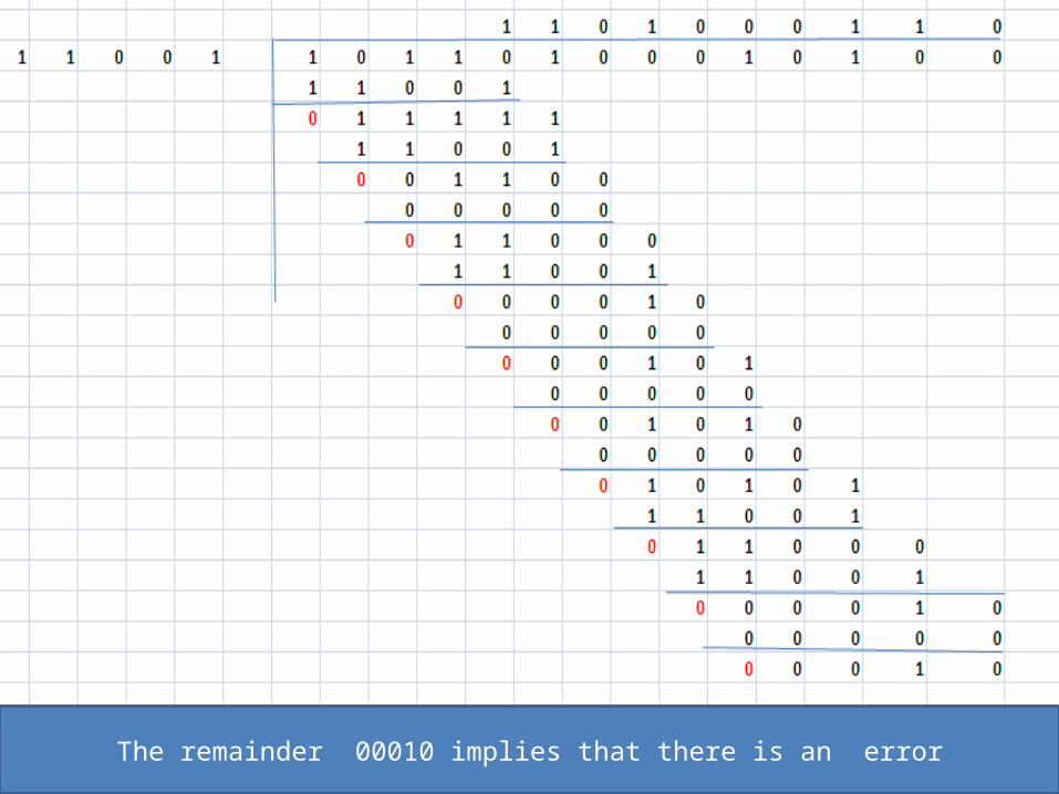
The remainder 00010 implies that there is an error
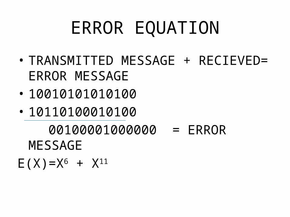
ERROR EQUATION
• TRANSMITTED MESSAGE + RECIEVED= ERROR MESSAGE
• 10010101010100• 10110100010100 00100001000000 = ERROR MESSAGEE(X)=X6 + X11
INSTANCES WHERE THE CRC IS FAILED TO ANSWER?
• THER ARE INSTANCES WHERE THE CRC WILL FAILED TO ANSWER, ONE SUCH INSTANCES WILL BE WHEN THERE ARE ERRORS INTRODUCED EQUAL TO THE POLYNOMIAL


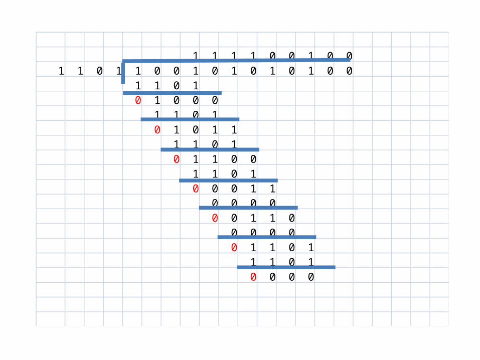
WHEN ERROR MESSAGE IS EQUAL TO THE POLYNOMIAL (EXAMPLE)
• ASSUME THE FOLLOWING• TRANSMITTED MESSAGE
• 100101010100• RECEIEVED MESSAGE
• 100101001101• POLYNOMIAL
• 1101• SHOW THAT CRC IS FAILED TO IDENTIFY THE ERROR
IN THE MESSAGE?
1 1 1 1 0 0 1 0 01 1 0 1 1 0 0 1 0 1 0 1 0 1 0 0
1 1 0 10 1 0 0 0
1 1 0 10 1 0 1 1
1 1 0 10 1 1 0 0
1 1 0 10 0 0 1 1
0 0 0 00 0 1 1 0
0 0 0 00 1 1 0 1
1 1 0 10 0 0 0
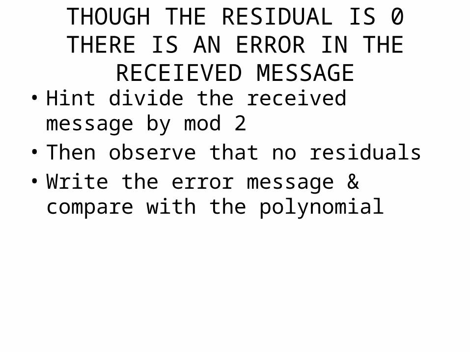
THOUGH THE RESIDUAL IS 0 THERE IS AN ERROR IN THE RECEIEVED MESSAGE
• Hint divide the received message by mod 2• Then observe that no residuals• Write the error message & compare with the
polynomial

TRY A CRC SUM
• TRANSMIT MESSAGE• 11001011101• POLYNOMIAL• 101101• FIND OUT THE CRC• DRAW THE CIRCUIT DIAGRAM AND SHOW
CLEARLY HOW YOU PRODUCE CRC?
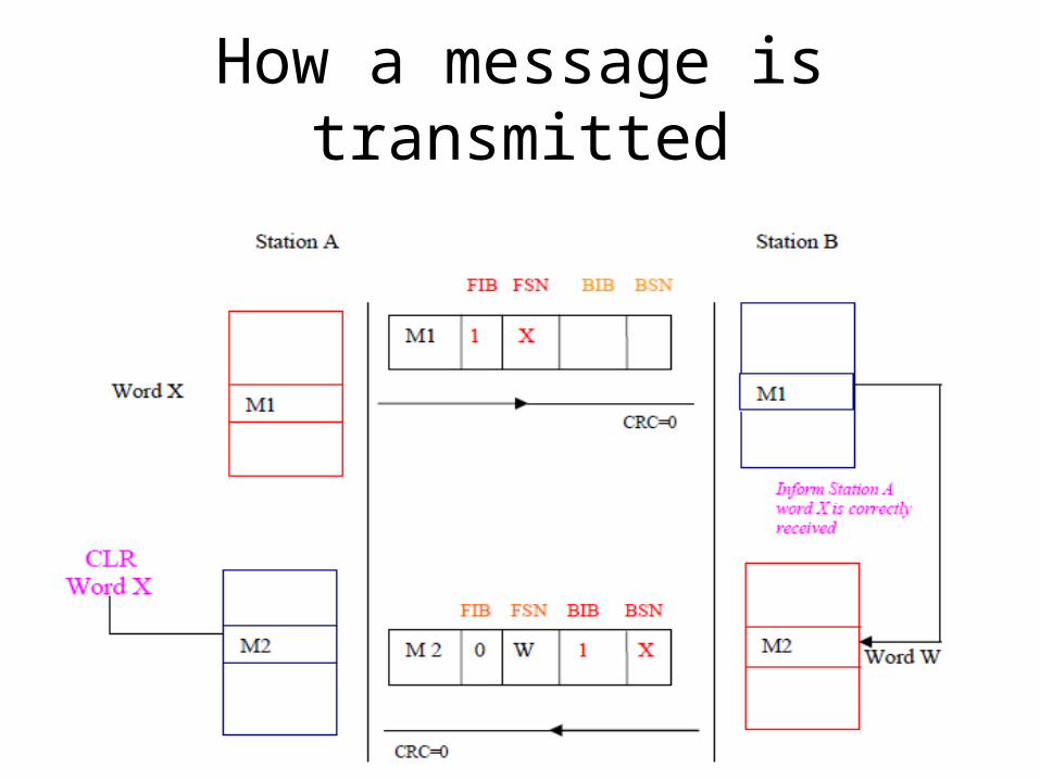
How a message is transmitted

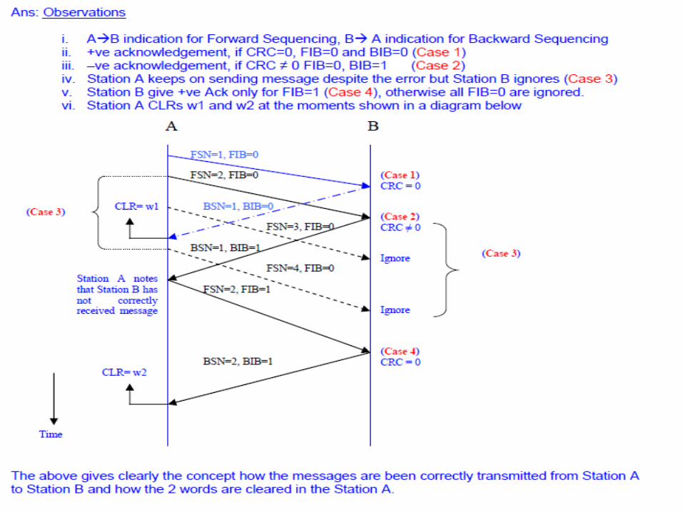
Preventive cycle retransmission method of error correction

Question on basic method

4 layers of CCITT no:7

Layer 4
Instructions DATA
User Part
Layer 3
LabelSIO
Signaling Link
Layer 2
W0
W127
Link Control
FSN=5,FIB=1CRC=0
Layer 1
Station A Station B
k1
k1
k2
Actual message
SCF K2
Message handline
Signal control
Message type
Error detection and correction
SCF=Sequence control field
Layer 2
SCF K2
Layer 3
K2
Layer 4
K1
SCF
BSN=5,BIB=1Clear W5
W5
OPC|DPC|CICLABEL CONTENTS
DPC=st B
How CCITT No:7 works- Study about the layered structure
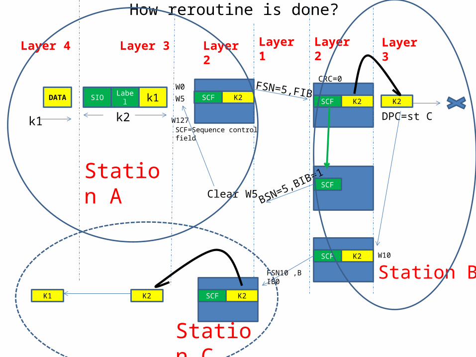
How reroutine is done?
Layer 4
DATA
Layer 3
LabelSIO
Layer 2
W0
W127
FSN=5,FIB=1CRC=0
Layer 1
Station A
k1
k1
k2
SCF K2
SCF=Sequence control field
Layer 2
SCF K2 K2
SCF
BSN=5,BIB=1Clear W5
W5
Station B
Layer 3
DPC=st C
Station C
SCF K2
SCF K2K2
W10
FSN10 ,BIB0
K1
OSI 7 LAYERS
• MUCH MORE VALUE ADDITION HAS BEEN ADDED TO THE MESSAGE PART IN OSI 7 LAYERS
• VIRTUALLY THE CCITT NO7 LAYER4 IS BEEN VALUE ADDED , WHILE THE OTHER PARTS REMAINS SAME.
• LAYER4 IS BEEN ADDED WITH ANOTHER 4 LAYERS, i.e TRANSPORT, SESSION, PRESENTATION & APPLICATION
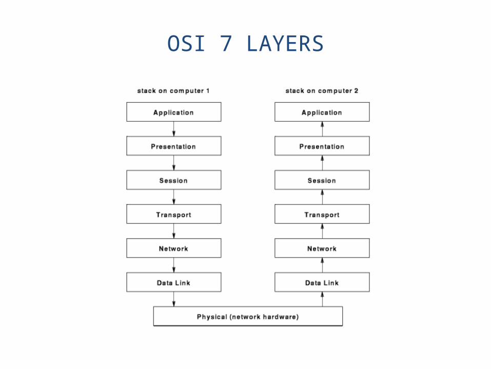
OSI 7 LAYERS

Physical Layer
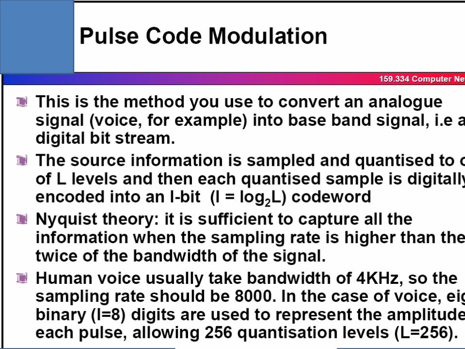
To transmit bits over a medium. To provide mechanical and electrical specificationsUnit is bits - A/D conversions, Error control coding, Multiplexing, Modulation
Data Link Layer
To organize bits into frames. To provide hop to hop delivery. Unit is frames- Buffering, Framing, Error control, Flow control
Network Layer
To move packets from source to destination. To provide internetworking. Unit is packets-Routing, Congestion control, Compatibility issues with internetworking

Transport Layer
To provide reliable process to process data delivery and recovery. Unit is segments.
Sessions Layer
To establish, manage and terminate sessions.Unit is message.
Presentation Layer
To translate, compress and encrypt data.Unit is message.
Application layer
To allow access to network structure. Manages programme requests that require access to services provided by a remote system.Unit is message.

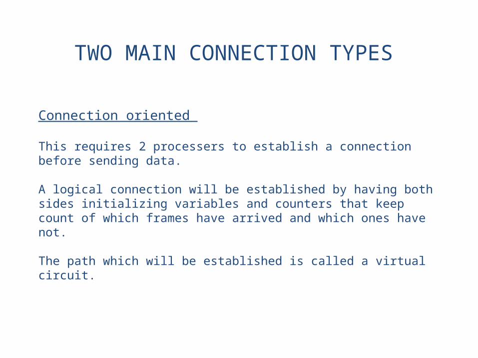
TWO MAIN CONNECTION TYPES
Connection oriented
This requires 2 processers to establish a connection before sending data.
A logical connection will be established by having both sides initializing variables and counters that keep count of which frames have arrived and which ones have not.
The path which will be established is called a virtual circuit.

Connectionless
In connection less the data packets are sent independent of each other so they might not arrive at the destination on proper order.
Unlike connection oriented, in connectionless an advanced set up is not required so the data frames can get lost, corrupted, duplicated or out of order.
In this context, packets are called datagrams. Datagrams carry full destination address and each is routed through the system independent of all the others.
TWO MAIN CONNECTION TYPES
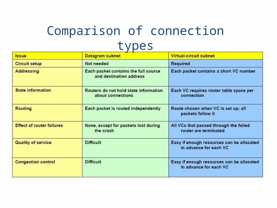
Comparison of connection types
TUTORIALS ON ERROR CONTROL
• EXPLAIN THE DIFFERENCE BETWEEN FORWARD AND BACKWARD ERROR CORRECTION, AND WHAT ARE ITS APPLICATION AREAS.
• SHOW AN ONE OCCATION THE CRC WILL NOT DETECT AN ERROR?
• CALCULATE CRC WHERE THE MESSAGE IS 1001010101 WHERE THE POLYNOMIAL USED IS 11001
• DRAW THE SCHMETIC DIAGRAM HOW YOU ARE GOING TO FORM THE CRC BY USING 1 BIT SHIFT REGISTERS, AND SHOW ALL THE STEPS UPTO THE FORMATION OF CRC.
DETAILS OF PHYSICAL LAYER• PHYSICAL LAYER CONSIST OF MANY TYPES OF
CONNECTIONS. THEY BOLONGS TO ONE OF THE FOLLOWING TYPES
• WIRED CONNECTION (ELECTRICAL SIGNALS THROUGHOUT)
• WIRELESS CONNECTIONS• OPTICAL FIBRE CONNECTIONS• LETS ANALYSE GENERALLY WHAT ARE THE
PHYSICAL CONNECTIONS

Transport Layer
To provide reliable process to process data delivery and recovery. Unit is segments.
Sessions Layer
To establish, manage and terminate sessions.Unit is message.
Presentation Layer
To translate, compress and encrypt data.Unit is message.
Application layer
To allow access to network structure. Manages programme requests that require access to services provided by a remote system.Unit is message.
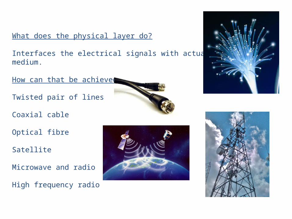
What does the physical layer do?
Interfaces the electrical signals with actual physical medium.
How can that be achieved?
Twisted pair of lines
Coaxial cable
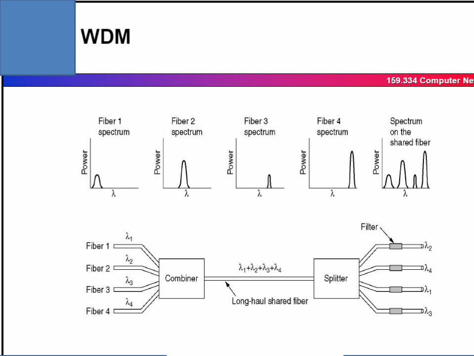
Optical fibre
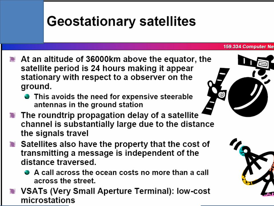
Satellite
Microwave and radio
High frequency radio


CONCLUTIONS
• WE HAVE STUDIED LAYER 1, THE DETAIED STUDY DONE IN PCM & HIGHER ORDER PCM WILL ALLOW YOU TO UNDERSTAND MORE ON TO THE PRACTICAL APPLICATION OF LAYER 1
• LAYER 2 & 3 ALREADY DETAILED OUT• IF YOU UNDERSTAND THE CONCEPTS UPTO
NOW, YOU CAN STUDY THE REST OF LAYERS IN OSI MODEL


