Page 1
ENTSO-E AISBL • Avenue Cortenbergh 100 • 1000 Brussels • Belgium • Tel +32 2 741 09 50 • Fax +32 2 741 09 51 • [email protected] • www.entsoe.eu
European Network of Transmission System Operators
for Electricity
COMMON INFORMATION MODEL (CIM) – MODEL EXCHANGE
PROFILE 1
10 MAY 2009 revised on 10 June 2014 to include IOP 2013 agreements
1ST
EDITION: BASED ON IEC 61970 CIM14
Page 2
Page 2 of 120
ENTSO-E AISBL • Avenue Cortenbergh 100 • 1000 Brussels • Belgium • Tel +32 2 741 09 50 • Fax +32 2 741 09 51 • [email protected] • www.entsoe.eu
European Network of Transmission System Operators
for Electricity
CIM MODEL EXCHANGE PROFILE - 1ST
EDITION
FOREWORD
This document is the first edition of the European Network of Transmission System Operators for
Electricity (ENTSO-E) Common Information Model (CIM) based data exchange format. The document
is based on the UCTE profile which has been issued on 10 May 2009 and adapted as an ENTSO-E
document.
Following the successful interoperability test held in March 2009 and consecutive decisions
by System Development Committee and System Operations Committee the first edition of
the ENTSO-E Profile is the valid version for data exchanges using CIM/XML format.
Next editions of this document will follow the roadmap future updates of the CIM/XML based
data exchange format which was approved by ENTSO-E in late 2009. An excerpt of the
roadmap is presented in Appendix B of this document. It defines principles and necessary
steps for further development, approval and implementation of the next releases of CIM for
ENTSO-E.
Following ENTSO-E CIM Interoperability Tests (IOP) in July 2011, an annex with additional
rules was added to this document for clarification purposes. A second and a third versions of
this annex were released after ENTSO-E CIM IOP in July 2012. Following ENTSO-E CIM
IOP in July 2013, a revision of the original document was made and the annex describing the
changes in the Profile 1 was integrated in this document. [R]
In order to facilitate versioning, the list of changes done to the original document is provided
in Appendix C. Alternatively, it is possible to search for the keyword “[R]” (for “Revision”)
which is used in the document to identify revised sections. [R]
Page 3
Page 3 of 120
ENTSO-E AISBL • Avenue Cortenbergh 100 • 1000 Brussels • Belgium • Tel +32 2 741 09 50 • Fax +32 2 741 09 51 • [email protected] • www.entsoe.eu
European Network of Transmission System Operators
for Electricity
CIM MODEL EXCHANGE PROFILE - 1ST
EDITION
CONTENTS
1 SCOPE .................................................................................................................... 8
2 NORMATIVE REFERENCES ........................................................................................ 8
3 OVERVIEW OF THE PROFILE ..................................................................................... 8
3.1 SUMMARY OF ENTSO-E CIM MODEL EXCHANGE REQUIREMENTS .................................................. 11 3.1.1 ENTSO-E DATA EXCHANGE PROCESSES ...................................................................................... 11 3.1.1.1 DAY-AHEAD CONGESTION FORECAST ............................................................................................ 11 3.1.1.2 SYSTEM DEVELOPMENT PROCESS (PLANNING) ............................................................................... 12 3.1.2 DATA MODELLING SCOPE .............................................................................................................. 13 3.1.3 INTERFACE FUNCTIONALITY ........................................................................................................... 13 3.2 TSOS AS MODEL AUTHORITY SETS ............................................................................................... 14 3.2.1 MODEL AUTHORITY SETS AND MRIDS............................................................................................ 14 3.2.2 FILE PACKAGING BY MODEL AUTHORITY SETS ................................................................................ 15 3.2.3 TESTING ....................................................................................................................................... 15 3.3 FORMATTING OF FILES IN MODEL EXCHANGES ................................................................................ 15 3.3.1 INTERNAL FILE STRUCTURE ........................................................................................................... 16 3.3.1.1 FILE HEADER ................................................................................................................................ 16 3.3.1.2 552 FILE BODY ............................................................................................................................. 16 3.3.1.2.1 ROLES AND MULTIPLICITY .............................................................................................................. 16 3.3.2 FILE TYPES .................................................................................................................................. 16 3.3.2.1 ENTSO-E COMMON OBJECTS ...................................................................................................... 17 3.3.2.2 TSO EQUIPMENT MODEL FILE ....................................................................................................... 17 3.3.2.3 X-NODE BOUNDARY TOPOLOGY FILE ............................................................................................. 18 3.3.2.4 TSO TOPOLOGY FILE ................................................................................................................... 18 3.3.2.5 TSO STATE VARIABLE FILE ........................................................................................................... 19 3.3.2.6 ENTSO-E TEST FILES .................................................................................................................. 19 3.3.3 FILE EXCHANGE ............................................................................................................................ 19 3.3.4 COMBINING FILES INTO COMPLETE MODELS ................................................................................... 20 3.3.4.1 XML MODEL VALIDITY .................................................................................................................. 20 3.4 ENTSO-E BUSINESS PROCESS USE CASES .................................................................................. 21 3.4.1 GENERAL ..................................................................................................................................... 21 3.4.2 BASIC KINDS OF EXCHANGES ........................................................................................................ 22 3.4.2.1 UPDATING ENTSO-E BASE .......................................................................................................... 22 3.4.2.2 EXCHANGING AN INTERNAL TSO MODEL ........................................................................................ 22 3.4.2.3 STUDY CASE EXCHANGE ............................................................................................................... 23
4 PROFILE CONSTRAINTS (FROM 61970-452) ............................................................ 24
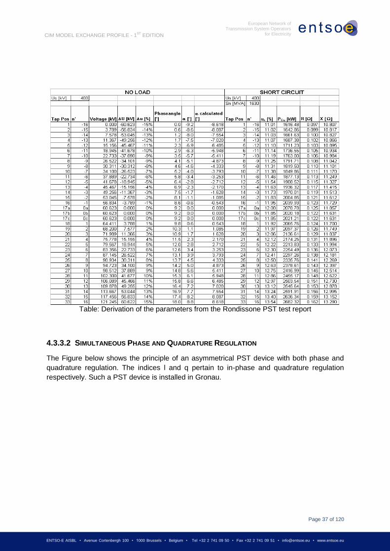
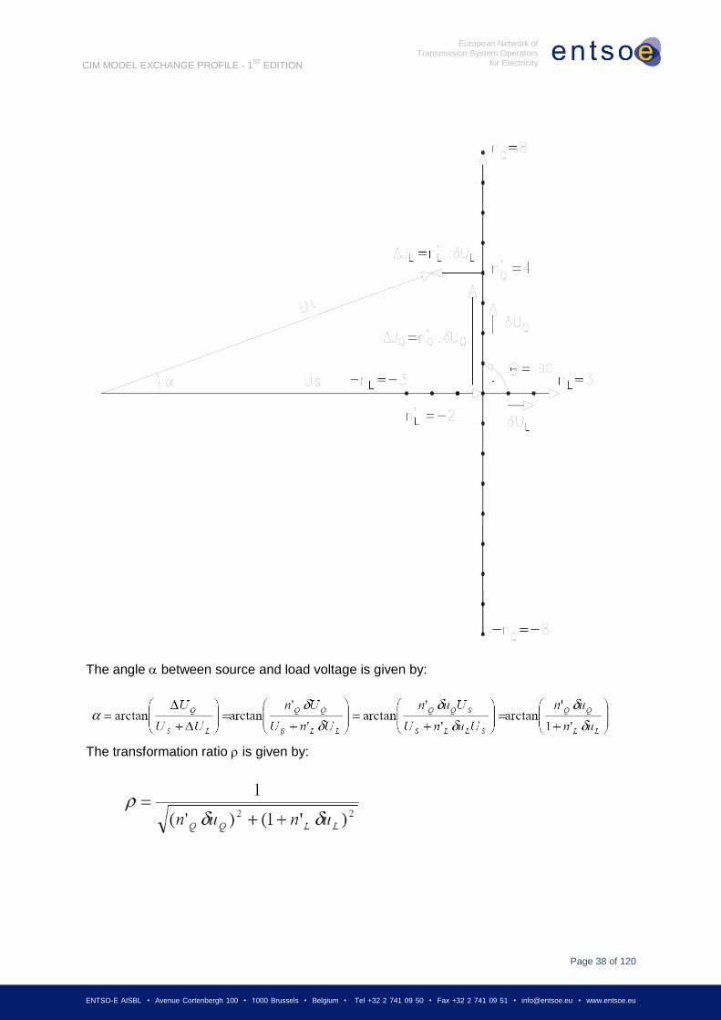
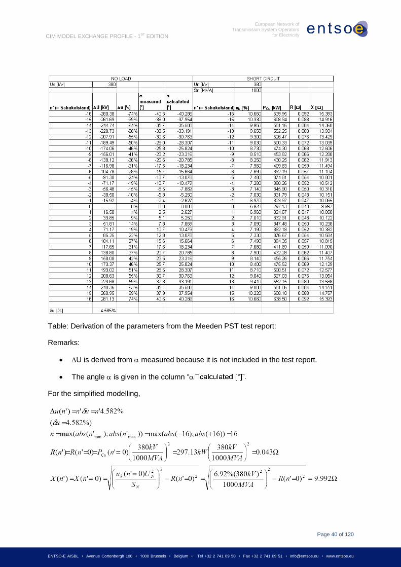
4.1 GENERAL ..................................................................................................................................... 24 4.2 TRANSFORMER MODELLING ........................................................................................................... 25 4.3 TRANSFORMER REGULATION ......................................................................................................... 26 4.3.1 MODELLING OF REGULATING TRANSFORMERS ................................................................................ 26 4.3.1.1 REGULATION ................................................................................................................................ 27 4.3.1.1.1 PHASE REGULATION ..................................................................................................................... 28 4.3.1.1.2 ANGLE REGULATION ..................................................................................................................... 29 4.3.2 EXPLANATION OF THE NEW PARAMETERS (XSTEPMIN, XSTEPMAX) ................................................. 34 4.3.2.1 SYMMETRICAL PHASE SHIFTER ...................................................................................................... 34 4.3.2.2 QUADRATIC BOOSTER ................................................................................................................... 35 4.3.3 EXAMPLES.................................................................................................................................... 35 4.3.3.1 DERIVATION OF THE PARAMETERS OF THE RONDISSONE TRANSFORMER........................................... 35 4.3.3.2 SIMULTANEOUS PHASE AND QUADRATURE REGULATION .................................................................. 37 4.3.3.3 DERIVATION OF THE PARAMETERS OF THE MEEDEN TRANSFORMER ................................................. 39 4.3.4 REMARKS ..................................................................................................................................... 41 4.4 VOLTAGE OR ACTIVE POWER REGULATION ..................................................................................... 41 4.5 MODELLING AUTHORITIES .............................................................................................................. 42
Page 4
Page 4 of 120
ENTSO-E AISBL • Avenue Cortenbergh 100 • 1000 Brussels • Belgium • Tel +32 2 741 09 50 • Fax +32 2 741 09 51 • [email protected] • www.entsoe.eu
European Network of Transmission System Operators
for Electricity
CIM MODEL EXCHANGE PROFILE - 1ST
EDITION
4.6 USE OF CURVES ........................................................................................................................... 42 4.6.1 GENERATING UNIT REACTIVE POWER LIMITS .................................................................................. 42
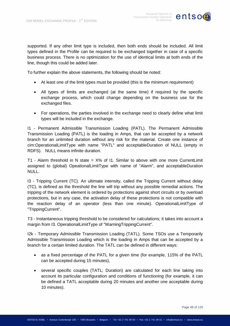
5 ENTSO-E PROFILE NOTES .................................................................................... 43
5.1 CIMTOOL PROFILE PROPERTIES ................................................................................................... 43 5.2 X-NODE CONTAINMENT ISSUES ..................................................................................................... 43 5.3 TRANSFORMER MAPPING CLARIFICATION ....................................................................................... 44 5.4 TRANSFORMER NO LOAD LOSSES ISSUE ........................................................................................ 44 5.5 TRANSFORMER REGULATION MAPPINGS ......................................................................................... 44 5.6 REGULATINGCONTROL MAPPINGS ................................................................................................. 45 5.7 STATICVARCOMPENSATOR INCLUSION QUESTION ........................................................................... 45 5.8 EQUIVALENT FLAG ON REAL MODELS ISSUE ................................................................................... 45 5.9 TRANSFORMER STEP IMPEDANCE MODELS ISSUE ........................................................................... 45 5.10 NAMING CONVENTIONS AND USE OF IDENTIFIEDOBJECT .................................................................. 45 5.11 TERMINAL CONNECTED EXPLANATION ............................................................................................ 46 5.12 GENERATINGUNIT SUBTYPES ISSUE ............................................................................................... 46 5.13 LIMIT TYPE ISSUE ......................................................................................................................... 47 5.14 MAPPING OF SOLVED STATE TO INJECTION VALUES ........................................................................ 49 5.15 SHUNTCOMPENSATOR SWITCHING AND TERMINAL CONNECTION ISSUE ............................................. 51 5.16 LINE ENDS FOR MUTUALCOUPLING ISSUE ....................................................................................... 51 5.17 MUTUALCOUPLING IDENTIFICATION ISSUE....................................................................................... 52 5.18 SHUNTCOMPENSATOR POSITIVE SEQUENCE IMPEDANCE PER SECTION ISSUE .................................. 52 5.19 CIMTOOL RDFS IMPROVEMENT ISSUE. ......................................................................................... 52 5.20 READING THE CIMTOOL PROFILE HTML OUTPUT. .......................................................................... 52 5.21 SVPOWERFLOW MODEL COVERAGE ISSUE. .................................................................................... 53 5.22 GENERATINGUNIT AND SYNCHRONOUSMACHINE MULTIPLICITY ISSUE .............................................. 53 5.23 DATATYPE MULTIPLIER AND UNITS DEFAULTS ISSUE ....................................................................... 53 5.24 SERIESCOMPENSATOR IS EXCLUDED FROM PROFILE ...................................................................... 54 5.25 ACTIVE POWER SLACK AND ANGLE REFERENCE SPECIFICATIONS DESCRIPTION ................................ 54 5.26 CONTINUOUS SVSHUNTCOMPENSATORSECTIONS AND SVTAPSTEP ISSUE ....................................... 55
6 ENTSO-E CIM MODEL EXCHANGE PROFILE SPECIFICATION ................................... 55
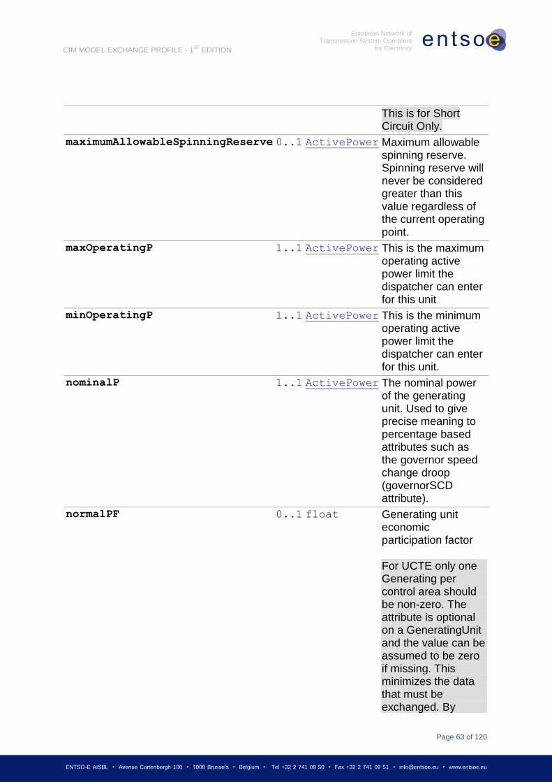
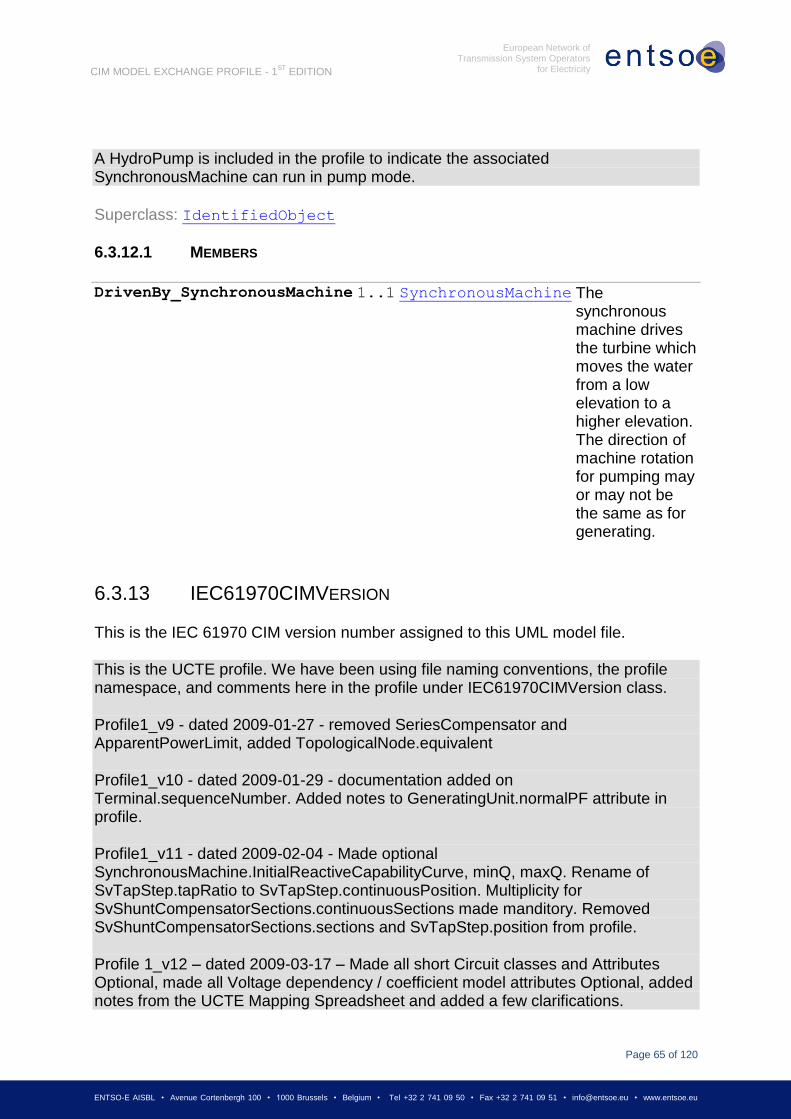
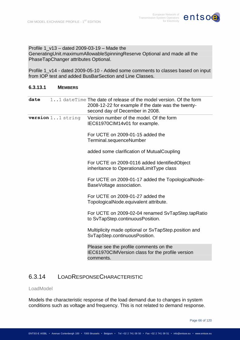
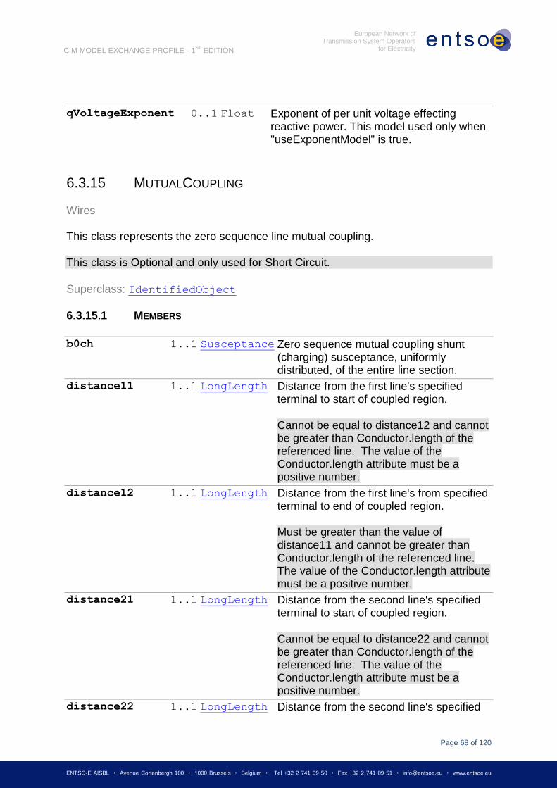
6.1 DETAILED MAPPING OF CLASSES TO ENTSO-E FILE TYPES ............................................................ 55 6.2 PROFILE DOCUMENTATION ............................................................................................................ 58 6.3 CONCRETE CLASSES .................................................................................................................... 59 6.3.1 ACLINESEGMENT ......................................................................................................................... 59 6.3.2 BASEVOLTAGE ............................................................................................................................. 59 6.3.2.1 MEMBERS .................................................................................................................................... 59 6.3.3 CONTROLAREA ............................................................................................................................. 59 6.3.3.1 MEMBERS .................................................................................................................................... 60 6.3.4 CONTROLAREAGENERATINGUNIT .................................................................................................. 60 6.3.4.1 MEMBERS .................................................................................................................................... 60 6.3.5 CURRENTLIMIT ............................................................................................................................. 60 6.3.5.1 MEMBERS .................................................................................................................................... 60 6.3.6 CURVEDATA ................................................................................................................................. 61 6.3.6.1 MEMBERS .................................................................................................................................... 61 6.3.7 ENERGYCONSUMER ...................................................................................................................... 61 6.3.7.1 MEMBERS .................................................................................................................................... 61 6.3.8 FOSSILFUEL ................................................................................................................................. 61 6.3.8.1 MEMBERS .................................................................................................................................... 62 6.3.9 GENERATINGUNIT ......................................................................................................................... 62 6.3.9.1 MEMBERS .................................................................................................................................... 62 6.3.10 GEOGRAPHICALREGION ................................................................................................................ 64 6.3.11 HYDROGENERATINGUNIT .............................................................................................................. 64 6.3.12 HYDROPUMP ................................................................................................................................ 64 6.3.12.1 MEMBERS .................................................................................................................................... 65 6.3.13 IEC61970CIMVERSION ............................................................................................................... 65 6.3.13.1 MEMBERS .................................................................................................................................... 66
Page 5
Page 5 of 120
ENTSO-E AISBL • Avenue Cortenbergh 100 • 1000 Brussels • Belgium • Tel +32 2 741 09 50 • Fax +32 2 741 09 51 • [email protected] • www.entsoe.eu
European Network of Transmission System Operators
for Electricity
CIM MODEL EXCHANGE PROFILE - 1ST
EDITION
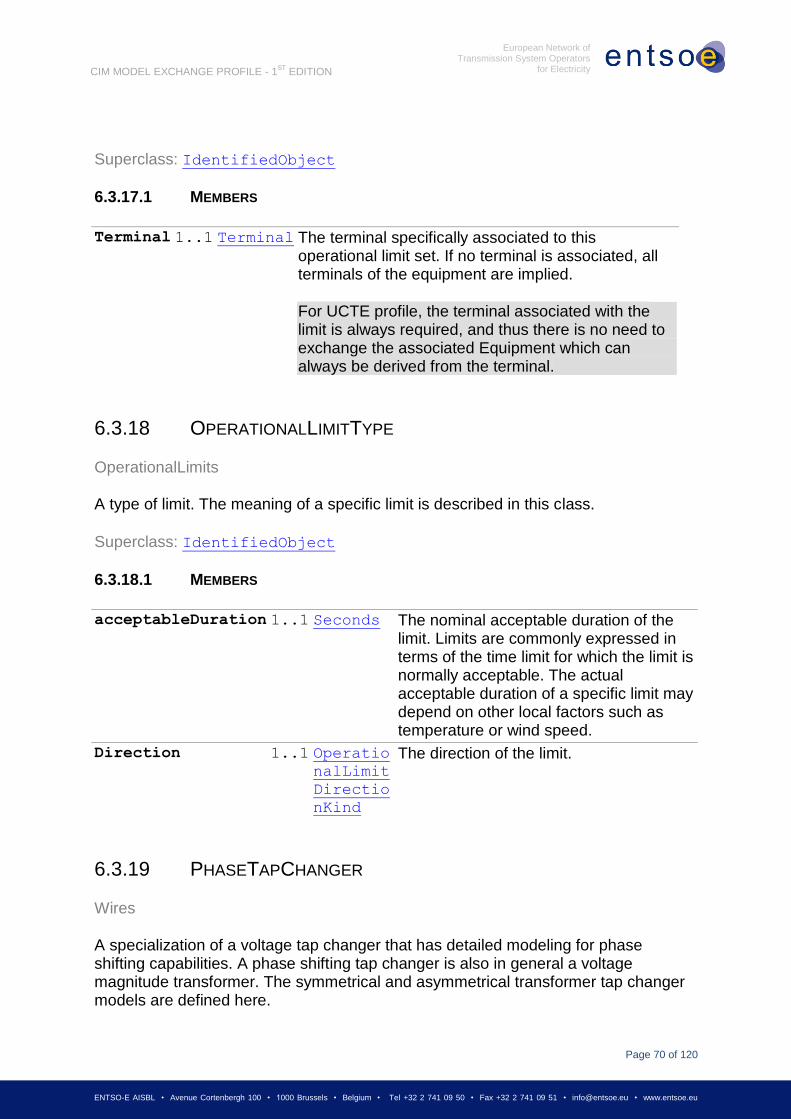
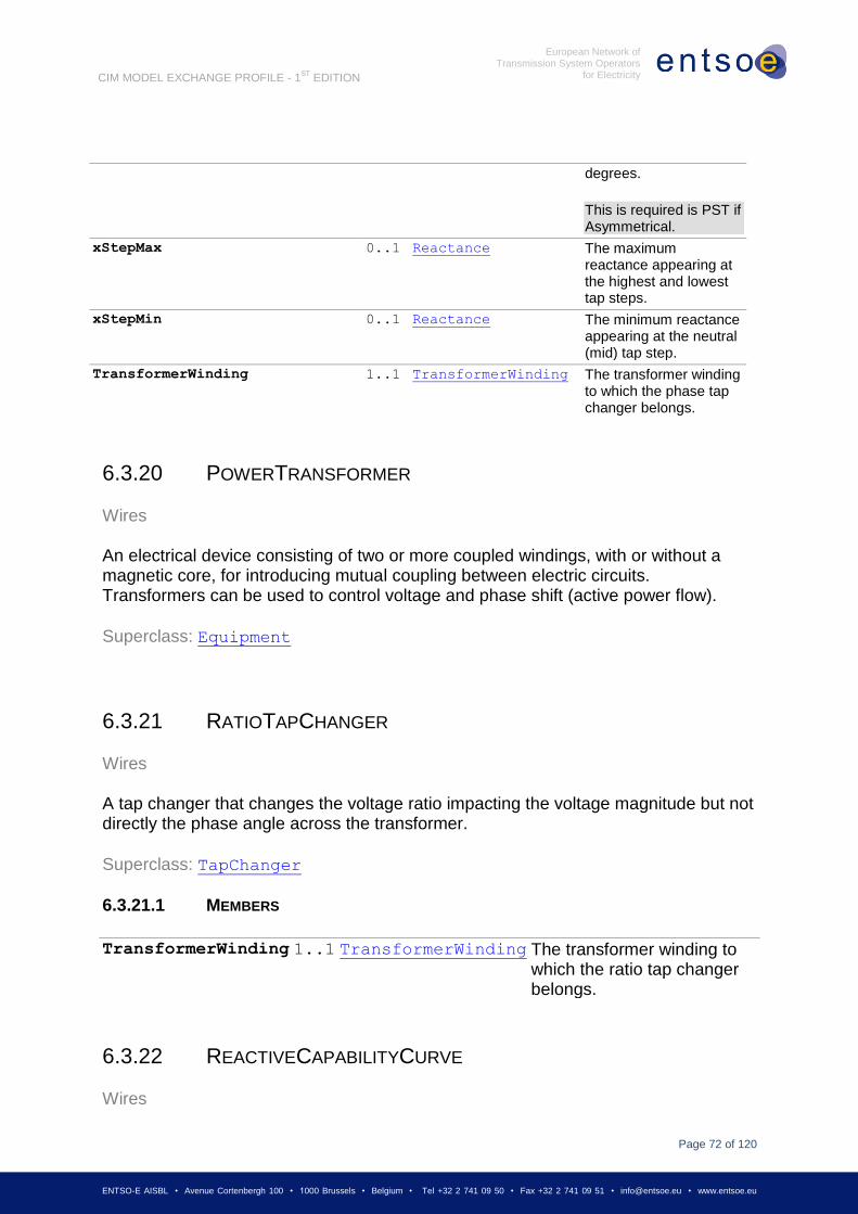
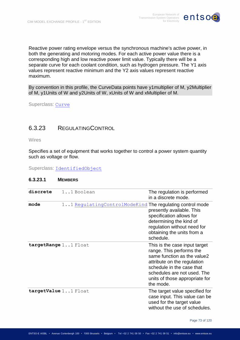
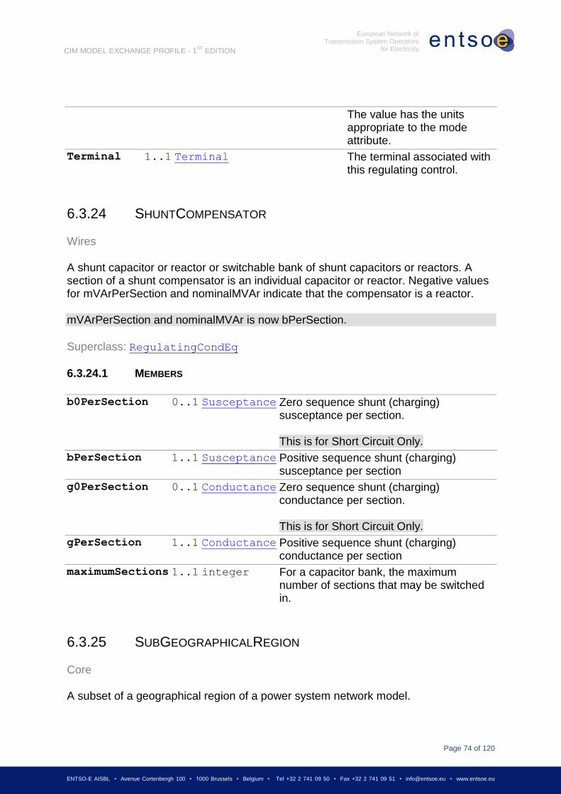
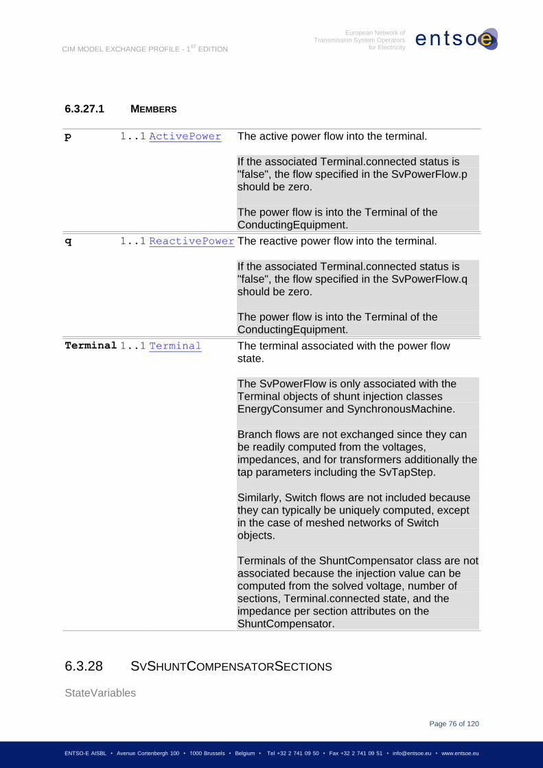
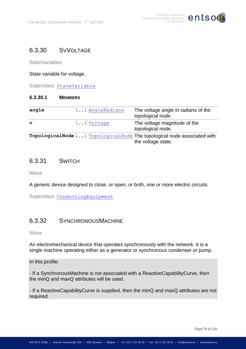
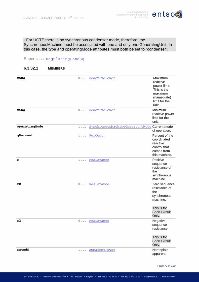
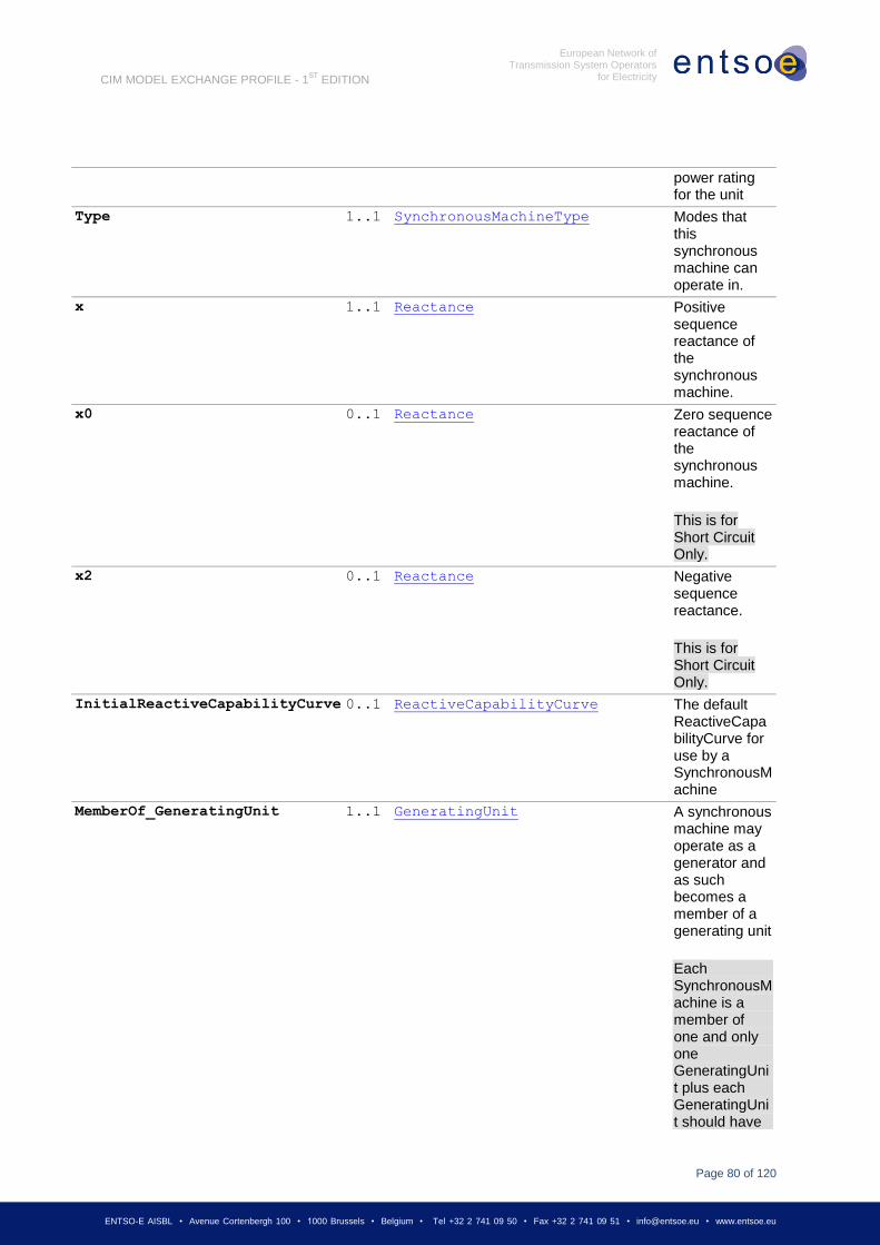
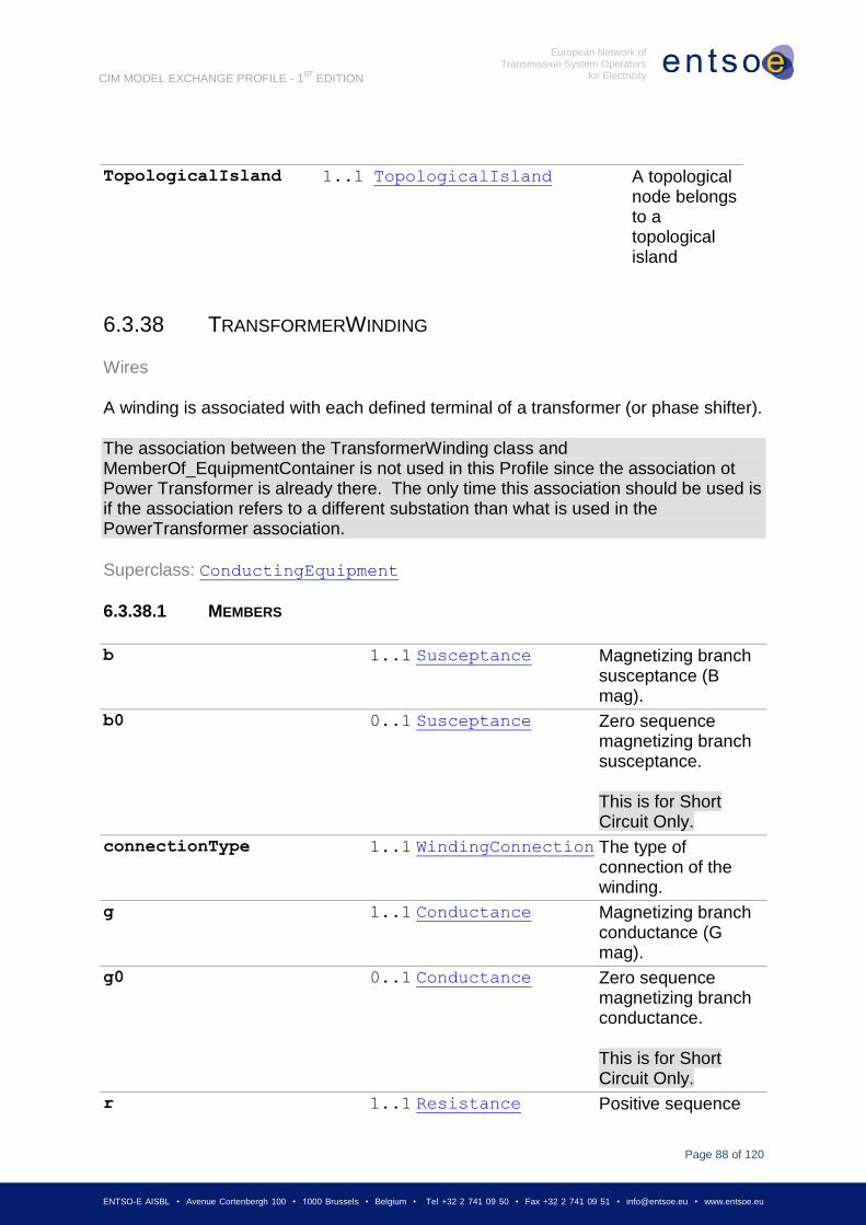
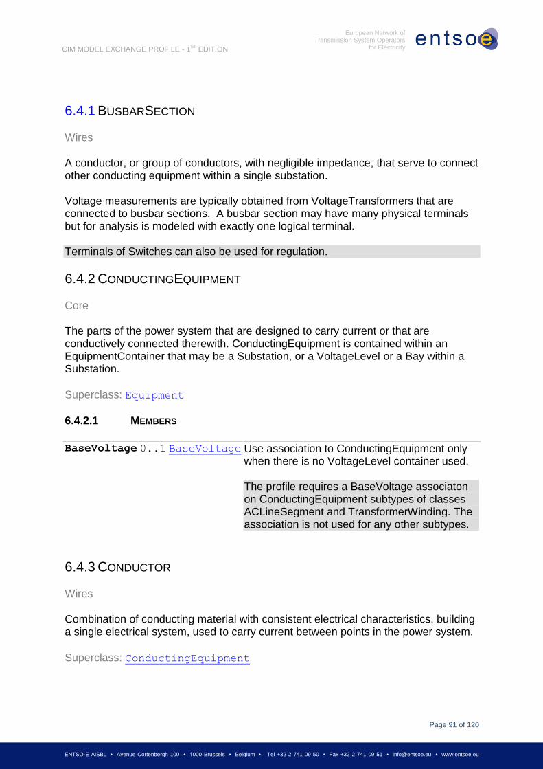
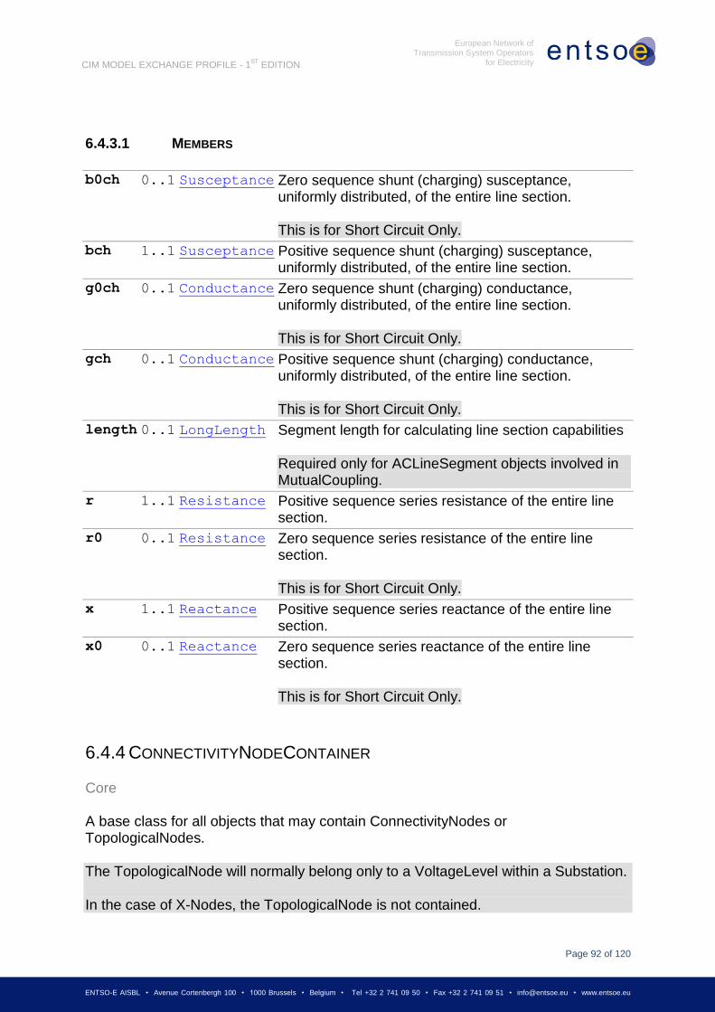
6.3.14 LOADRESPONSECHARACTERISTIC ................................................................................................. 66 6.3.14.1 MEMBERS .................................................................................................................................... 67 6.3.15 MUTUALCOUPLING ........................................................................................................................ 68 6.3.15.1 MEMBERS .................................................................................................................................... 68 6.3.16 NUCLEARGENERATINGUNIT ........................................................................................................... 69 6.3.17 OPERATIONALLIMITSET ................................................................................................................. 69 6.3.17.1 MEMBERS .................................................................................................................................... 70 6.3.18 OPERATIONALLIMITTYPE ............................................................................................................... 70 6.3.18.1 MEMBERS .................................................................................................................................... 70 6.3.19 PHASETAPCHANGER .................................................................................................................... 70 6.3.19.1 MEMBERS .................................................................................................................................... 71 6.3.20 POWERTRANSFORMER .................................................................................................................. 72 6.3.21 RATIOTAPCHANGER ..................................................................................................................... 72 6.3.21.1 MEMBERS .................................................................................................................................... 72 6.3.22 REACTIVECAPABILITYCURVE ......................................................................................................... 72 6.3.23 REGULATINGCONTROL .................................................................................................................. 73 6.3.23.1 MEMBERS .................................................................................................................................... 73 6.3.24 SHUNTCOMPENSATOR .................................................................................................................. 74 6.3.24.1 MEMBERS .................................................................................................................................... 74 6.3.25 SUBGEOGRAPHICALREGION .......................................................................................................... 74 6.3.25.1 MEMBERS .................................................................................................................................... 75 6.3.26 SUBSTATION ................................................................................................................................. 75 6.3.26.1 MEMBERS .................................................................................................................................... 75 6.3.27 SVPOWERFLOW ........................................................................................................................... 75 6.3.27.1 MEMBERS .................................................................................................................................... 76 6.3.28 SVSHUNTCOMPENSATORSECTIONS ............................................................................................... 76 6.3.28.1 MEMBERS .................................................................................................................................... 77 6.3.29 SVTAPSTEP ................................................................................................................................. 77 6.3.29.1 MEMBERS .................................................................................................................................... 77 6.3.30 SVVOLTAGE ................................................................................................................................. 78 6.3.30.1 MEMBERS .................................................................................................................................... 78 6.3.31 SWITCH ........................................................................................................................................ 78 6.3.32 SYNCHRONOUSMACHINE ............................................................................................................... 78 6.3.32.1 MEMBERS .................................................................................................................................... 79 6.3.33 TERMINAL..................................................................................................................................... 81 6.3.33.1 MEMBERS .................................................................................................................................... 81 6.3.34 THERMALGENERATINGUNIT ........................................................................................................... 83 6.3.34.1 MEMBERS .................................................................................................................................... 83 6.3.35 TIEFLOW ...................................................................................................................................... 84 6.3.35.1 MEMBERS .................................................................................................................................... 84 6.3.36 TOPOLOGICALISLAND .................................................................................................................... 84 6.3.36.1 MEMBERS .................................................................................................................................... 84 6.3.37 TOPOLOGICALNODE ...................................................................................................................... 84 6.3.37.1 MEMBERS .................................................................................................................................... 85 6.3.38 TRANSFORMERWINDING ................................................................................................................ 88 6.3.38.1 MEMBERS .................................................................................................................................... 88 6.3.39 VOLTAGELEVEL ............................................................................................................................ 90 6.3.39.1 MEMBERS .................................................................................................................................... 90 6.3.40 VOLTAGELIMIT .............................................................................................................................. 90 6.3.40.1 MEMBERS .................................................................................................................................... 90 6.3.41 WINDGENERATINGUNIT................................................................................................................. 90 6.4 ABSTRACT CLASSES ..................................................................................................................... 90 6.4.1 BUSBARSECTION .......................................................................................................................... 91 6.4.2 CONDUCTINGEQUIPMENT .............................................................................................................. 91 6.4.2.1 MEMBERS .................................................................................................................................... 91 6.4.3 CONDUCTOR ................................................................................................................................ 91 6.4.3.1 MEMBERS .................................................................................................................................... 92 6.4.4 CONNECTIVITYNODECONTAINER .................................................................................................... 92 6.4.5 CURVE ......................................................................................................................................... 93 6.4.6 EQUIPMENT .................................................................................................................................. 93
Page 6
Page 6 of 120
ENTSO-E AISBL • Avenue Cortenbergh 100 • 1000 Brussels • Belgium • Tel +32 2 741 09 50 • Fax +32 2 741 09 51 • [email protected] • www.entsoe.eu
European Network of Transmission System Operators
for Electricity
CIM MODEL EXCHANGE PROFILE - 1ST
EDITION
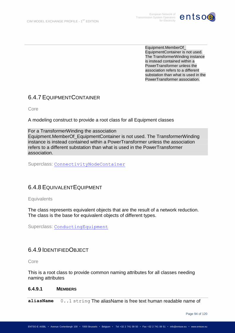
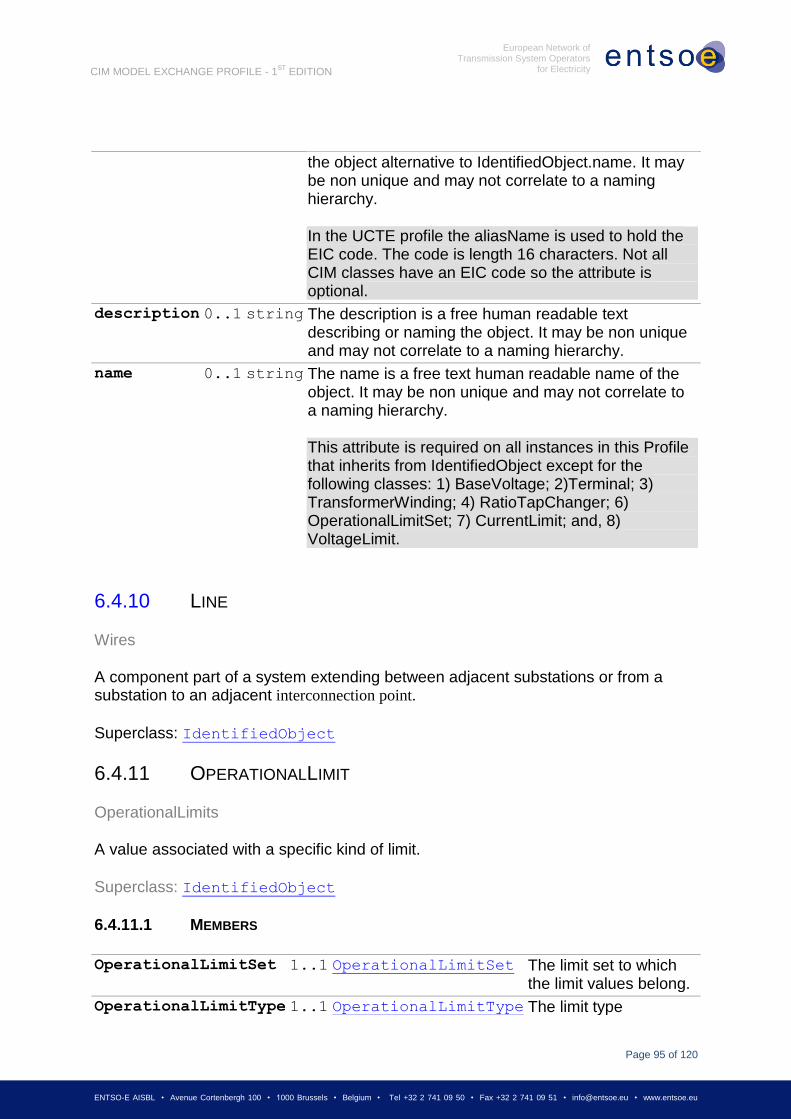
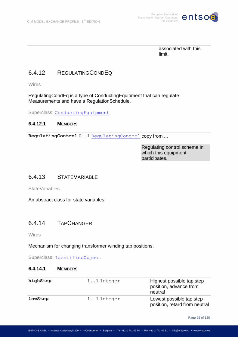
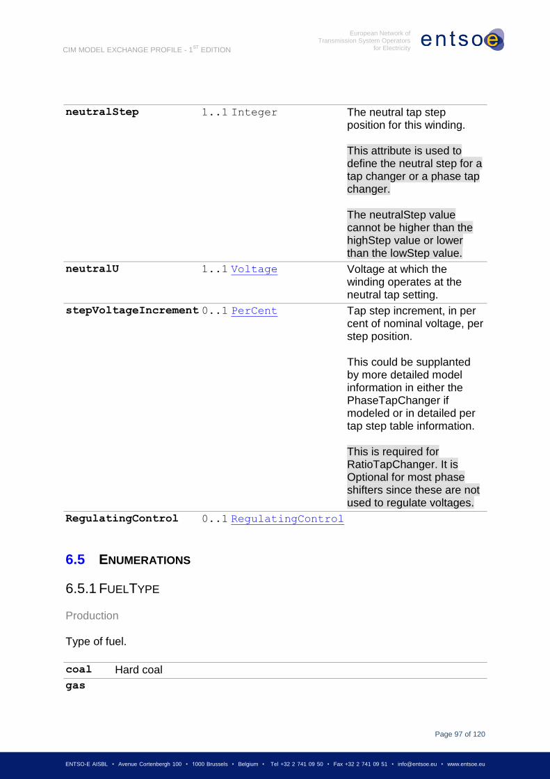
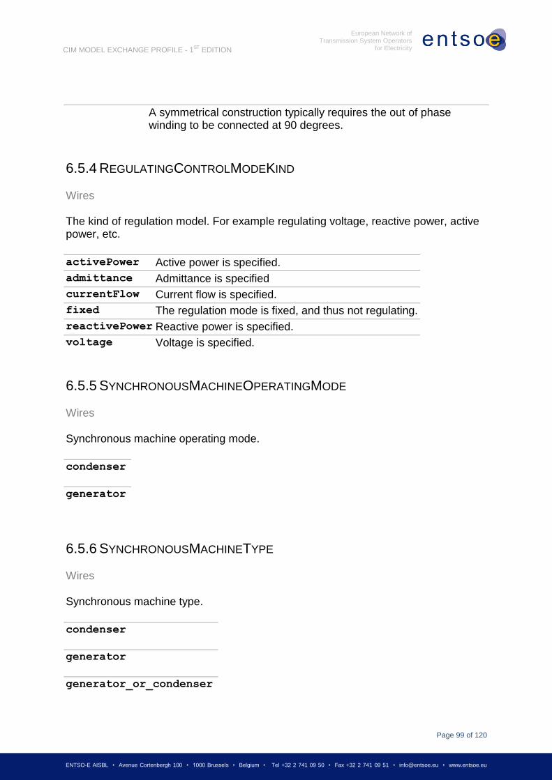
6.4.6.1 MEMBERS .................................................................................................................................... 93 6.4.7 EQUIPMENTCONTAINER ................................................................................................................. 94 6.4.8 EQUIVALENTEQUIPMENT ............................................................................................................... 94 6.4.9 IDENTIFIEDOBJECT ........................................................................................................................ 94 6.4.9.1 MEMBERS .................................................................................................................................... 94 6.4.10 LINE ............................................................................................................................................. 95 6.4.11 OPERATIONALLIMIT ....................................................................................................................... 95 6.4.11.1 MEMBERS .................................................................................................................................... 95 6.4.12 REGULATINGCONDEQ ................................................................................................................... 96 6.4.12.1 MEMBERS .................................................................................................................................... 96 6.4.13 STATEVARIABLE ........................................................................................................................... 96 6.4.14 TAPCHANGER ............................................................................................................................... 96 6.4.14.1 MEMBERS .................................................................................................................................... 96 6.5 ENUMERATIONS ............................................................................................................................ 97 6.5.1 FUELTYPE .................................................................................................................................... 97 6.5.2 OPERATIONALLIMITDIRECTIONKIND ............................................................................................... 98 6.5.3 PHASETAPCHANGERKIND ............................................................................................................. 98 6.5.4 REGULATINGCONTROLMODEKIND ................................................................................................. 99 6.5.5 SYNCHRONOUSMACHINEOPERATINGMODE .................................................................................... 99 6.5.6 SYNCHRONOUSMACHINETYPE ....................................................................................................... 99 6.5.7 WINDINGCONNECTION ................................................................................................................ 100 6.5.8 WINDINGTYPE ............................................................................................................................ 100 6.6 DATATYPES ................................................................................................................................ 100 6.6.1 ACTIVEPOWER ........................................................................................................................... 100 6.6.2 ANGLEDEGREES ......................................................................................................................... 100 6.6.3 ANGLERADIANS .......................................................................................................................... 101 6.6.4 APPARENTPOWER ...................................................................................................................... 101 6.6.5 CONDUCTANCE ........................................................................................................................... 101 6.6.6 CURRENTFLOW .......................................................................................................................... 101 6.6.7 LONGLENGTH ............................................................................................................................. 101 6.6.8 MONEY ...................................................................................................................................... 102 6.6.9 PERCENT ................................................................................................................................... 102 6.6.10 REACTANCE ............................................................................................................................... 102 6.6.11 REACTIVEPOWER ....................................................................................................................... 102 6.6.12 RESISTANCE ............................................................................................................................... 102 6.6.13 SECONDS ................................................................................................................................... 102 6.6.14 SUSCEPTANCE............................................................................................................................ 103 6.6.15 VOLTAGE ................................................................................................................................... 103
7 AMPLIFICATIONS AND CONVENTIONS .................................................................... 103
7.1 NORMATIVE STRING TABLES ........................................................................................................ 103 7.2 ROLES AND MULTIPLICITY ............................................................................................................ 104
8 APPENDIX A: ENTSO-E NAMING CONVENTION .................................................... 105
8.1 FILE HEADER & FILE NAME ........................................................................................................... 105 8.2 IDENTIFIEDOBJECT.DESCRIPTION (256 CHARACTERS MAXIMUM) ..................................................... 105 8.3 IDENTIFIEDOBJECT.NAME (32 CHARACTERS MAXIMUM) .................................................................. 106 8.4 IDENTIFIEDOBJECT.ALIASNAME .................................................................................................... 108 8.5 EXAMPLE ................................................................................................................................... 109
9 APPENDIX B: INTEROPERABILITY TESTS AND A ROADMAP FOR IMPLEMENTATION OF
THE CIM/XML DATA EXCHANGE FORMAT .............................................................. 113
10 APPENDIX C: TRACH CHANGES ........................................................................ 117
Page 7
Page 7 of 120
ENTSO-E AISBL • Avenue Cortenbergh 100 • 1000 Brussels • Belgium • Tel +32 2 741 09 50 • Fax +32 2 741 09 51 • [email protected] • www.entsoe.eu
European Network of Transmission System Operators
for Electricity
CIM MODEL EXCHANGE PROFILE - 1ST
EDITION
Abbreviations
IEC The International Electrotechnical Commission, headquartered in Geneva.
TSO Transmission System Operator. ENTSO-E is divided into member TSOs
MRID A CIM Master Resource Identifier
UCTE DEF UCTE ASCII Data Exchange Format
Page 8
Page 8 of 120
ENTSO-E AISBL • Avenue Cortenbergh 100 • 1000 Brussels • Belgium • Tel +32 2 741 09 50 • Fax +32 2 741 09 51 • [email protected] • www.entsoe.eu
European Network of Transmission System Operators
for Electricity
CIM MODEL EXCHANGE PROFILE - 1ST
EDITION
1 SCOPE
The ENTSO-E CIM Model Exchange Profile is an ENTSO-E standard that is based on the
CIM standards produced by IEC TC57/WG13.
The purpose of this standard is to define how members of ENTSO-E, using software from
different vendors, will exchange network modelling information as required by the ENTSO-E
business activities.
This standard is limited to describing the interface between members’ software. It does not
govern any activity or dictate any software design within a member’s software systems.
The purpose of this document is to define the standard in sufficient detail to allow software
implementers to conform to the standard and thereby interoperate as ENTSO-E requires.
2 NORMATIVE REFERENCES
The data content of a model exchange is derived from Revision 14 of the IEC CIM, which is
the working version for 2009. The resulting profile data model is completely described in this
profile document, which relies only on the following other documents:
IEC 61970-552: CIM Model Exchange Format. This document describes how model
information is formatted for exchange.
The intent for the future is that the final version of Revision 14 of the CIM (at the end of 2009)
shall cover the requirements of both ENTSO-E exchange and the other IEC standards. Once
this convergence is reached, the ENTSO-E standard shall depend on and incorporate by
reference the following normative IEC standards:
IEC 61970-452: CIM Model Exchange.
IEC 61970-456: Steady-State Solution Interface.
IEC 61970-552: CIM Model Exchange Format.
3 OVERVIEW OF THE PROFILE
The European Network of Transmission System Operators for Electricity (ENTSO-E) speaks
for all electric TSOs in the EU and others connected to their networks, with one voice for all
regions, and for all their technical and market issues.
Important Europe-wide planning and operations roles are assigned to ENTSO-E in new
European legislation: The Regulation on cross-border exchanges of electricity that is a part
of the European Union 3rd Energy Package legislation adopted by the European Parliament
Page 9
Page 9 of 120
ENTSO-E AISBL • Avenue Cortenbergh 100 • 1000 Brussels • Belgium • Tel +32 2 741 09 50 • Fax +32 2 741 09 51 • [email protected] • www.entsoe.eu
European Network of Transmission System Operators
for Electricity
CIM MODEL EXCHANGE PROFILE - 1ST
EDITION
in 2009 establishes the ENTSO for Electricity in order to ensure optimal management of the
electricity transmission network and to allow trading and supplying electricity across borders
in the Community. The Regulation sees the need for increased cooperation and coordination
among transmission system operators to create network codes for providing and managing
effective and transparent access to the transmission networks across borders, and to ensure
coordinated and sufficiently forward looking planning and sound technical evolution of the
transmission system in the Community, including the creation of interconnection capacities,
with due regard to the environment.
The European TSOs agree and have founded ENTSO-E in late 2008 ahead of approval and
implementation of the 3rd Energy Package. They intend to play an active and important role
in the European rule setting process and to push network codes and pan-European network
planning forward urgently.
In ENTSO-E the TSOs cooperate regionally and on the European scale, and through
ENTSO-E they communicate their needs and positions on European and regional issues.
ENTSO-E’s activities are organized in the three Committees along which the website
(www.entsoe.eu) is structured, for System Development, System Operations and Market,
and are supported by a Legal & Regulatory Group.
The activities are focused on:
reliable operation,
optimal management,
sound technical evolution of the European electricity grid,
security of supply,
meeting the needs of the Internal Energy Market and facilitating market integration,
network development statements,
network codes,
promotion of relevant R&D and the public acceptability of transmission infrastructure,
consultation with stakeholders and positions towards energy policy issue
System Operations and System Development (planning) processes within ENTSO-E depend
heavily on network analysis of the interconnection. The accuracy of such analysis depends in
turn on accurate network models, which, as a general rule, must extend beyond the territory
of any individual member TSO. (In some cases, these models will need to cover the entire
interconnection – in others only the immediate neighbourhood of a TSO). ENTSO-E is
responsible for issuing of Ten-Year Network Development Plan that requires detailed and
accurate modelling of the pan-European power system. Therefore:
TSOs must be able to obtain models of one another’s territory;
Page 10
Page 10 of 120
ENTSO-E AISBL • Avenue Cortenbergh 100 • 1000 Brussels • Belgium • Tel +32 2 741 09 50 • Fax +32 2 741 09 51 • [email protected] • www.entsoe.eu
European Network of Transmission System Operators
for Electricity
CIM MODEL EXCHANGE PROFILE - 1ST
EDITION
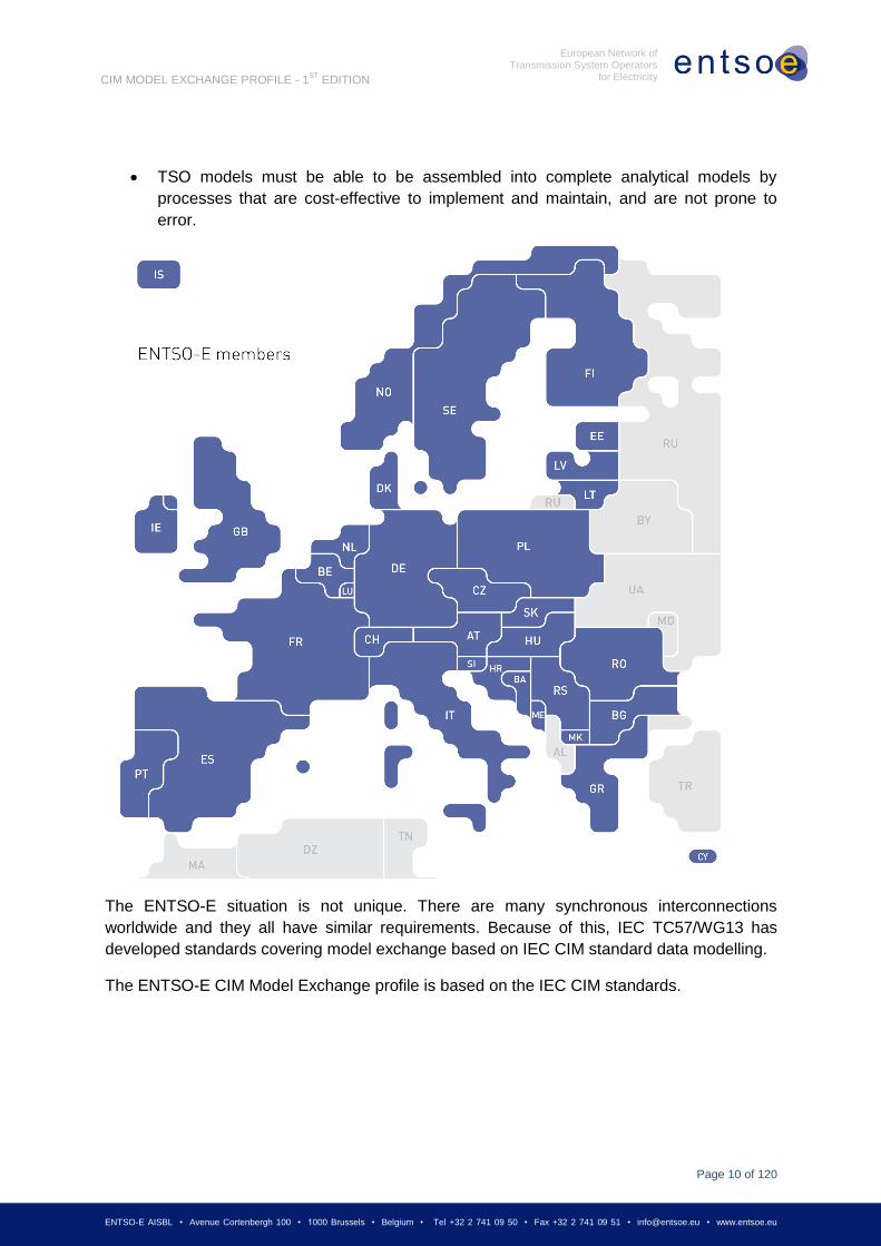
TSO models must be able to be assembled into complete analytical models by
processes that are cost-effective to implement and maintain, and are not prone to
error.
The ENTSO-E situation is not unique. There are many synchronous interconnections
worldwide and they all have similar requirements. Because of this, IEC TC57/WG13 has
developed standards covering model exchange based on IEC CIM standard data modelling.
The ENTSO-E CIM Model Exchange profile is based on the IEC CIM standards.
Page 11
Page 11 of 120
ENTSO-E AISBL • Avenue Cortenbergh 100 • 1000 Brussels • Belgium • Tel +32 2 741 09 50 • Fax +32 2 741 09 51 • [email protected] • www.entsoe.eu
European Network of Transmission System Operators
for Electricity
CIM MODEL EXCHANGE PROFILE - 1ST
EDITION
3.1 SUMMARY OF ENTSO-E CIM MODEL EXCHANGE
REQUIREMENTS
3.1.1 ENTSO-E DATA EXCHANGE PROCESSES
The business processes supported by these file exchanges fall into two major categories:
System Operations process
System Development (planning) process
3.1.1.1 DAY-AHEAD CONGESTION FORECAST
An example for daily analytical operational process is so called Day Ahead Congestion
Forecast (DACF) that is currently applied in the ENTSO-E Regional Group Continental
Europe. In this process,
Each TSO prepares a power flow case covering exactly its own territory representing
each hour of the following day (based on day-ahead market outcomes). These cases
are transferred to a central server.
The full set of submitted cases may be checked for mutual compatibility. (i.e. Do the
boundary exchange conditions match reasonably well?)
Once all cases are submitted, each TSO downloads from the central server the cases
posted by their neighbouring TSOs. These are combined with their own models to
form a set of study models on which they can analyse the congestion in their region
for the next day.
Congestion result cases may be exchanged among TSOs, as the situation warrants.
This work is carried out primarily with planning tools running bus-branch models (although an
obvious possible variation on the process would be to generate cases with EMS tools).
Even though the DACF process is not a real-time process like state estimation, it is quite
similar in that a sequence of cases is produced representing periodic intervals. The solution
values will change at each case, but the network model will change rarely and the topology
will change occasionally. Conserving file size is a concern, and that concern is addressed if
the standard allows the network model and topology to be exchanged incrementally.
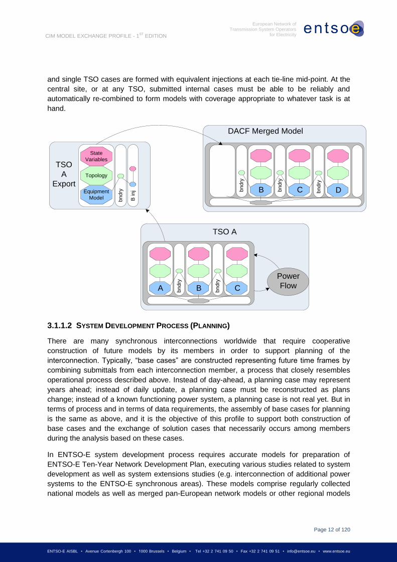
DACF raises another set of requirements, however. Unlike the state estimator scenarios,
which feature complete transfer of a solution, the DACF involves a lot of merging and
extracting of pieces of solutions. In Figure below, TSO A runs power flows to develop a
picture of its territory for the following day. This would be done with models that include
representations of neighbouring TSOs. They must post, however, only the part of the model
representing their own territory, and this must be a stand-alone solved power flow. In
ENTSO-E, boundaries between TSOs are, by agreement, always at the mid-point of tie-lines,
Page 12
Page 12 of 120
ENTSO-E AISBL • Avenue Cortenbergh 100 • 1000 Brussels • Belgium • Tel +32 2 741 09 50 • Fax +32 2 741 09 51 • [email protected] • www.entsoe.eu
European Network of Transmission System Operators
for Electricity
CIM MODEL EXCHANGE PROFILE - 1ST
EDITION
and single TSO cases are formed with equivalent injections at each tie-line mid-point. At the
central site, or at any TSO, submitted internal cases must be able to be reliably and
automatically re-combined to form models with coverage appropriate to whatever task is at
hand.
3.1.1.2 SYSTEM DEVELOPMENT PROCESS (PLANNING)
There are many synchronous interconnections worldwide that require cooperative
construction of future models by its members in order to support planning of the
interconnection. Typically, “base cases” are constructed representing future time frames by
combining submittals from each interconnection member, a process that closely resembles
operational process described above. Instead of day-ahead, a planning case may represent
years ahead; instead of daily update, a planning case must be reconstructed as plans
change; instead of a known functioning power system, a planning case is not real yet. But in
terms of process and in terms of data requirements, the assembly of base cases for planning
is the same as above, and it is the objective of this profile to support both construction of
base cases and the exchange of solution cases that necessarily occurs among members
during the analysis based on these cases.
In ENTSO-E system development process requires accurate models for preparation of
ENTSO-E Ten-Year Network Development Plan, executing various studies related to system
development as well as system extensions studies (e.g. interconnection of additional power
systems to the ENTSO-E synchronous areas). These models comprise regularly collected
national models as well as merged pan-European network models or other regional models
Equipment
Model
Power
Flow
TSO A
Topology
TSO
A
Export
State
Variables
A B
B
C
C
DACF Merged Model
D
bn
dry
B in
j bn
dry
bn
dry
bn
dry
bn
dry
bn
dry
Page 13
Page 13 of 120
ENTSO-E AISBL • Avenue Cortenbergh 100 • 1000 Brussels • Belgium • Tel +32 2 741 09 50 • Fax +32 2 741 09 51 • [email protected] • www.entsoe.eu
European Network of Transmission System Operators
for Electricity
CIM MODEL EXCHANGE PROFILE - 1ST
EDITION
for medium and long term time horizons. Due to the variety of system studies, responsibility
for merging the models is shared between different ENTSO-E bodies.
3.1.2 DATA MODELLING SCOPE
The first edition of the ENTSO-E CIM Model Exchange Profile is intended to meet the
requirements for accurate modelling of the ENTSO-E interconnection for power flow and
short circuit applications. Detailed requirements may be found in various publically available
ENTSO-E documents. Data content included in the first edition is a superset of the UCTE
Data Exchange Format (UCTE-DEF) that was developed to serve Day Ahead Congestion
Forecast process in the former UCTE (now ENTSO-E Regional Group Continental Europe),
although the structure is changed to align with IEC CIM modelling.
The data modelling scope documented in detail in Section 6 is derived from Revision 14 of
the CIM, which is the 2009 update to the CIM.
There are a few areas where full compliance with “UCTE DEF” data definitions is postponed
to the second edition of the profile in order to maintain an optimal development and testing
schedule. These areas include:
Tabular specification of transformer impedance data for each tap step (#TT card in
the UCTE DEF – ASCII format).
The intent in designing this standard is that the requirements of other network analysis
applications may be met in future revisions by straightforward extensions to the data model –
i.e. without major changes in the design.
3.1.3 INTERFACE FUNCTIONALITY
The following basic interface operations are sufficient to satisfy ENTSO-E network analysis
requirements:
TSO Internal Model Export. A TSO may use the profile to export its internal network
model in such a way that it can be easily and unambiguously combined with other
TSO internal models to make up complete models for analytical purposes.
TSO Internal Model Import. An analyst may use the profile to import exported TSO
models in such a way that they can be easily and unambiguously combined to make
up complete models for analytical purposes.
Solved Case Exchange. Any steady-state solution case created by one party,
covering any territory, may be sent to any other party using the profile. In such an
exchange, it shall be possible for the receiver to discern how the case modelling
relates to TSO internal models.
ENTSO-E business processes are, of course, more complex than these operations, but what
is important to notice is that all processes may be supported using only these basic kinds of
interoperation.
Page 14
Page 14 of 120
ENTSO-E AISBL • Avenue Cortenbergh 100 • 1000 Brussels • Belgium • Tel +32 2 741 09 50 • Fax +32 2 741 09 51 • [email protected] • www.entsoe.eu
European Network of Transmission System Operators
for Electricity
CIM MODEL EXCHANGE PROFILE - 1ST
EDITION
3.2 TSOS AS MODEL AUTHORITY SETS
3.2.1 MODEL AUTHORITY SETS AND MRIDS
The CIM concept of Model Authority Sets is adopted as the means to enable merge or
extraction of TSO models. Model Authority Sets allow an interconnection model to be divided
into disjoint sets of objects, and that in turn allows different parties to take responsibility for
different parts of the complete model.
In any model exchange governed by the profile, each model object has an ENTSO-E
MRID.
o Across all ENTSO-E models, the model object instance that represents a given
real world line, transformer, or whatever will always have the same MRID.
o Within any one model, object MRIDs are unique, since the same element would
not be represented twice.
o By agreement, ENTSO-E MRIDs are algorithm-generated 60 character GUIDs.
Each object instance is assigned to one and only one Model Authority Set. There are
two types of Model Authority Sets:
o Boundary sets contain boundary objects that mark the boundary between
region models. Boundary sets are managed by one authority but defined by
mutual agreement.
o Regional sets contain regional model objects. Objects in regional sets have
internal associations and may have associations to boundary objects, but
regional objects may never have associations to objects in other regional sets.
This allows regional modelling to be carried out independently of other regions.
ENTSO-E will have one boundary set.
o The boundary set contains TopologicalNode objects located at the mid-points of
ties between the TSO territories. Boundary set will correspond exactly to the
common ENTSO-E X-nodes list used for all ENTSO-E data exchanges
including DACF exchange in Regional Group Continental Europe.
o ENTSO-E (the Secretariat) is the Model Authority that manages the boundary
set. By definition the boundary set is available to all ENTSO-E TSOs.
Each TSO in ENTSO-E is a Model Authority and manages a Model Authority Set in its
area of responsibility. The TSO as Model Authority is also responsible for assigning
object MRIDs in its area set.
Page 15
Page 15 of 120
ENTSO-E AISBL • Avenue Cortenbergh 100 • 1000 Brussels • Belgium • Tel +32 2 741 09 50 • Fax +32 2 741 09 51 • [email protected] • www.entsoe.eu
European Network of Transmission System Operators
for Electricity
CIM MODEL EXCHANGE PROFILE - 1ST
EDITION
o Note that in current practice, the territory that a TSO models may not be exactly
the same as the territory it governs. In this standard, “TSO territory” always
refers to the model responsibility territory.
The IEC Std. 61970-552 requires only that in a given full model, object “RDFids” must
be unique. In CIM applied for ENTSO-E the following requirement are added:
o MRIDs shall always be used as RDFids.
o RDFids must be persistent from one model exchange to another.
o This enables any two exchanges to be compared by comparing the MRIDs, and
thus any case being exchanged can be compared to “official” versions of any
TSO’s internal model.
o This also enables incremental changes to be developed with reference to one
model instance and used in a different model instance.
3.2.2 FILE PACKAGING BY MODEL AUTHORITY SETS
In CIM model exchanges, the main effect of Model Authority Sets is that each Model
Authority Set is packaged in its own file.
The IEC 61970-552 specification is still used to format a file, but the file only contains
the objects in one Model Authority Set.
A given regional file, formatted in “full model” form, is not entirely self-consistent
because it contains some associations to objects in a boundary set.
Many practical exchanges will only require updates of particular regional files.
ENTSO-E exchanges will follow this same practice.
3.2.3 TESTING
Tests performed for interoperability testing of this first edition (UCTE IOP March 2009) used
single, complete models and did not deal with Model Authority Sets. For testing purposes,
there was one default Model Authority Set and all objects are in it by default.
In July 2011, ENTSO-E CIM IOP tested exchange of complete models for two different
Model Authority Sets. [R]
3.3 FORMATTING OF FILES IN MODEL EXCHANGES
ENTSO-E CIM Model Exchanges are also packaged into files based on the kind of
information in each file. This division typically segregates less rapidly changing information
from more rapidly changing information, setting up the situation where some exchanges are
Page 16
Page 16 of 120
ENTSO-E AISBL • Avenue Cortenbergh 100 • 1000 Brussels • Belgium • Tel +32 2 741 09 50 • Fax +32 2 741 09 51 • [email protected] • www.entsoe.eu
European Network of Transmission System Operators
for Electricity
CIM MODEL EXCHANGE PROFILE - 1ST
EDITION
smaller because they only contain files that changed. In this section, the rules for formatting
files and how files are combined to form complete case specifications are presented.
3.3.1 INTERNAL FILE STRUCTURE
This section defines file conventions that apply to all ENTSO-E files.
Files have naming conventions and headers containing ENTSO-E specific
information.
File bodies contain the IEC 61970-552 XML.
3.3.1.1 FILE HEADER
No file headers were used in the model files for the interoperability test performed in March
2009. The vendors importer and exporter tools handled all file references/linkages between
files used for a specific Test Case.
3.3.1.2 552 FILE BODY
The body of each file is formatted according to the IEC 61970-552 Specification – CIM Model
Exchange Format.
Files may contain objects with associations to objects that will be packaged in a different file.
This situation means that the file by itself is ‘incomplete’ – it may have dangling references
and cannot be used except when combined with the contents of another file. When this
occurs, validation for completeness has to wait until all the parts are present.
3.3.1.2.1 ROLES AND MULTIPLICITY
In the profile UML, all associations are bidirectional but an association instance is specified
only at one end in the XML. The profile documentation describes the association with the end
used. It is legal to include both ends of an association in the XML, but only the end
designated by the profile is official.
3.3.2 FILE TYPES
This section defines the requirements for specific types of files, as illustrated in the following
figure that depicts partitioning of models.
Page 17
Page 17 of 120
ENTSO-E AISBL • Avenue Cortenbergh 100 • 1000 Brussels • Belgium • Tel +32 2 741 09 50 • Fax +32 2 741 09 51 • [email protected] • www.entsoe.eu
European Network of Transmission System Operators
for Electricity
CIM MODEL EXCHANGE PROFILE - 1ST
EDITION
3.3.2.1 ENTSO-E COMMON OBJECTS
This file contains objects that are intended to be shared by all the TSOs in creating their
models.
BaseVoltage objects define the base voltages that may be used in the TSO models.
3.3.2.2 TSO EQUIPMENT MODEL FILE
A TSO Equipment Model File describes the equipment in the TSO’s internal territory. Each
TSO is a separate Model Authority Set. At this level there are no connections to boundary
model authority sets, because there is no connectivity described in the ENTSO-E profile.
An ENTSO-E Equipment Model file consists of:
CIM Equipment
o Connectivity is not included (ConnectivityNodes and references to them).
o Switches are only included if they are to be retained.
o By convention, equivalent injections at X-nodes are represented by an
EnergyConsumer instance in the TSO Equipment Model files at each end.
o To establish limits on equipment terminal flows or voltage, OperationalLimitSets
are defined.
Global
MA
Regional
Model Authority
Equipment
Model
Topology
Bndry
MA
Regional
Model Authority
Equipment
Model
Topology
Regional
Model Authority
Equipment
Model
Topology
Bndry
MA
Partition by Object Instance according to Model AuthorityP
art
itio
n b
y C
IM S
ch
em
a E
lem
en
ts
Common
Objects
GlobalState
Variables
Page 18
Page 18 of 120
ENTSO-E AISBL • Avenue Cortenbergh 100 • 1000 Brussels • Belgium • Tel +32 2 741 09 50 • Fax +32 2 741 09 51 • [email protected] • www.entsoe.eu
European Network of Transmission System Operators
for Electricity
CIM MODEL EXCHANGE PROFILE - 1ST
EDITION
ENTSO-E branches may have up to “N” OperationalLimits in an
OperationalLimitSet associated with branch terminals. The term
“operational” is a CIM definition and it is not the same as ENTSO-E
definitions. Any limits for operational, planning or other purposes can be
exchanged using this object.
ENTSO-E voltage limits must be specified as an OperationalLimitSet
associated with the terminal of a conducting equipment instance at the
TopologicalNode and containing one high VoltageLimit and one low
VoltageLimit.
Regulating Controls
o RegulatingControl targetValue and targetRange are specified for each voltage
and flow control.
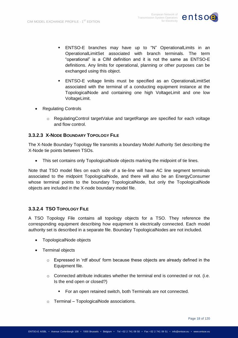
3.3.2.3 X-NODE BOUNDARY TOPOLOGY FILE
The X-Node Boundary Topology file transmits a boundary Model Authority Set describing the
X-Node tie points between TSOs.
This set contains only TopologicalNode objects marking the midpoint of tie lines.
Note that TSO model files on each side of a tie-line will have AC line segment terminals
associated to the midpoint TopologicalNode, and there will also be an EnergyConsumer
whose terminal points to the boundary TopologicalNode, but only the TopologicalNode
objects are included in the X-node boundary model file.
3.3.2.4 TSO TOPOLOGY FILE
A TSO Topology File contains all topology objects for a TSO. They reference the
corresponding equipment describing how equipment is electrically connected. Each model
authority set is described in a separate file. Boundary TopologicalNodes are not included.
TopologicalNode objects
Terminal objects
o Expressed in ‘rdf about’ form because these objects are already defined in the
Equipment file.
o Connected attribute indicates whether the terminal end is connected or not. (i.e.
Is the end open or closed?)
For an open retained switch, both Terminals are not connected.
o Terminal – TopologicalNode associations.
Page 19
Page 19 of 120
ENTSO-E AISBL • Avenue Cortenbergh 100 • 1000 Brussels • Belgium • Tel +32 2 741 09 50 • Fax +32 2 741 09 51 • [email protected] • www.entsoe.eu
European Network of Transmission System Operators
for Electricity
CIM MODEL EXCHANGE PROFILE - 1ST
EDITION
External associations may exist to X-node objects.
If a terminal is not connected, it should still have an association to the
TopologicalNode that it would close into.
3.3.2.5 TSO STATE VARIABLE FILE
A TSO State Variable Case File contains all objects, over and above TSO Model files and an
X-node file, required to complete the specification of a steady-state solution. An instance
consists of:
State Variables
o Solved voltage, angle given by the SvVoltage class relating to TopologicalNode.
o Injections given by the SvPowerFlow class.
Load at EnergyConsumer terminals.
Generation at SynchronousMachine terminals.
(Optional) flows at other ConductingEquipment.
o Injections due to capacitor switching given by ShuntCompensatorSections.
o Tap positions given by the SvTapStep class.
3.3.2.6 ENTSO-E TEST FILES
For testing purposes of the first edition (UCTE IOP March 2009), all of the test cases were
defined without any division into model authority sets. Thus there were a total of three files
for each case:
ENTSO-E Common Objects file (for the IOP Mach 2009, the contents of this file was
included in the Case Equipment Model file);
Case Equipment Model file;
Case Topology file;
Case State Variable file.
3.3.3 FILE EXCHANGE
It is common that a given exchange consists of multiple files. All files in a given logical
exchange unit will be zipped together.
The following exchange dependencies should be considered for each individual model:
If the Equipment file is changed, all three files (Equipment, Topology & State
Variable) must be sent as part of any exchange.
Page 20
Page 20 of 120
ENTSO-E AISBL • Avenue Cortenbergh 100 • 1000 Brussels • Belgium • Tel +32 2 741 09 50 • Fax +32 2 741 09 51 • [email protected] • www.entsoe.eu
European Network of Transmission System Operators
for Electricity
CIM MODEL EXCHANGE PROFILE - 1ST
EDITION
If the Topology file is changed, the Topology file and the State Variables file must be
sent as part of any exchange.
If only the State Variable file is changed, only the State Variable file must be sent as
part of any exchange.
It is NOT valid to exchange a Topology or a State Variable file from one model and an
Equipment file from another model (or from an entity that has changed the Equipment file)
and attempt to merge all three files into one merged model.
3.3.4 COMBINING FILES INTO COMPLETE MODELS
A complete ‘model’ for some purpose will normally be made up of information from multiple
files. These files will be disjointed in terms of the XML content of their file bodies. In other
words, among files that are to be combined, there is no overlap – each object, association or
attribute appears in one and only one of the files being combined.
There are many possible ways of managing files and forming complete models from them.
Part of the reason for the division into files is to create better flexibility in how complete
models for different purposes are formed from base parts. Model management systems can
be designed based around this capability that will be very useful. But there also needs to be
a simple, easy-to-implement method of combining files, and that is the main focus of this
section.
The basic method of combining files into models is simply to concatenate the XML content of
the files into a larger XML file – and then process that file as a complete XML obeying the
profile given in this document and the 61970-552 formatting specification.
Some examples of complete models are the following:
If you combine the ENTSO-E common objects file and the X-node boundary topology
file with the equipment model file and the topology model file for a given TSO, then
you get a model that would validate representing the TSO independent of other
TSOs.
If you combine the ENTSO-E common objects file with all equipment model files and
all topology files and all state variable files, then you get a complete power flow case
for the entire ENTSO-E model.
3.3.4.1 XML MODEL VALIDITY
In order to be considered a valid model, a given combined set of XML must adhere to the
following criteria:
The file must be well-formed as defined by the Extensible Markup Language (XML)
1.0 (Second Edition) (http://www.w3.org/TR/REC-xml).
Page 21
Page 21 of 120
ENTSO-E AISBL • Avenue Cortenbergh 100 • 1000 Brussels • Belgium • Tel +32 2 741 09 50 • Fax +32 2 741 09 51 • [email protected] • www.entsoe.eu
European Network of Transmission System Operators
for Electricity
CIM MODEL EXCHANGE PROFILE - 1ST
EDITION
The file must adhere to the rules set forth in the Simplified RDF Syntax for Power
System Model Exchange.
(http://www.langdale.com.au/CIMXML/PSModelExchange.pdf)
The file must contain CIM entities which are valid according to the CIM RDF Schema
file.
3.4 ENTSO-E BUSINESS PROCESS USE CASES
This section describes how the exchanges defined in the preceding section are used to
accomplish specific actions within ENTSO-E business processes.
3.4.1 GENERAL
The picture below describes how exchanges occur in ENTSO-E business processes.
All studies and data manipulation occur at one of the TSOs (or ENTSO-E body, TSO
consortium, Regions – Regional Groups, etc.). In the most cases, the ENTSO-E server is
simply a common server for exchange of files.
TSO Model Management at a TSO may simply be a file management system for cases, but
may also be a more sophisticated model management database application that allows:
Exploration of cases.
Modification of case data – especially of the TSO internal system. With change
management and other aids.
Other
TSOs
ENTSO-E
Projects
TSO
ConsortiumRegionsOperational
processes
System studies
processesDACFReference
cases
2DACF
(planned)Snapshots
Others-
on request
Planning
Various
studies
Mid-term Long-term
System
extension
Others such as
wind integration,
etc.
ENTSO-E
Other
servers
ENTSO-E
FTP serversTSO 1, TSO 2
, …
TSO 3, TSO 4
TSO 5, …
TSO 6,
TSO 7,
…
- frequent
- regular, but not frequent
- on request
Page 22
Page 22 of 120
ENTSO-E AISBL • Avenue Cortenbergh 100 • 1000 Brussels • Belgium • Tel +32 2 741 09 50 • Fax +32 2 741 09 51 • [email protected] • www.entsoe.eu
European Network of Transmission System Operators
for Electricity
CIM MODEL EXCHANGE PROFILE - 1ST
EDITION
Mixing and matching of file components to build new cases.
TSO Applications at a TSO provide the analytical functionality that generates solved cases
for various kinds of analytical studies. If those cases are to be shared, they must be
generated in the standard ENTSO-E CIM Profile.
3.4.2 BASIC KINDS OF EXCHANGES
ENTSO-E business processes are all based on a few basic types of exchanges:
Updating ENTSO-E Base files (X-node Topology or Common Object files).
Exchanging a case that represents a TSO internal system at a point in time.
Exchanging complete study cases for a particular analytical purpose.
Note that each “case” normally consists of multiple “files” as described in earlier sections of
this specification.
3.4.2.1 UPDATING ENTSO-E BASE
Two base files are maintained by ENTSO-E Secretariat.
ENTSO-E Common Objects file (at first stage common objects file is included in the
equipment file)
X-node Topology file (Boundary file)
These files change infrequently. ENTSO-E Secretariat ensures that they are available to all
TSOs.
3.4.2.2 EXCHANGING AN INTERNAL TSO MODEL
A number of business processes require each TSO to publish models of its internal territory
at a particular point in time. Some processes, like DACF, require a sequence of cases
representing a sequence of points in time.
To describe its internal territory in a single stand-alone exchange, a TSO must prepare the
following files:
An Equipment Model file for its own model authority set.
o Includes an EnergyConsumer object connected to each of its boundary X-
nodes.
A Topology file for its own model authority set.
A State Variable file defines the state.
To update such a model in a sequence of cases:
Page 23
Page 23 of 120
ENTSO-E AISBL • Avenue Cortenbergh 100 • 1000 Brussels • Belgium • Tel +32 2 741 09 50 • Fax +32 2 741 09 51 • [email protected] • www.entsoe.eu
European Network of Transmission System Operators
for Electricity
CIM MODEL EXCHANGE PROFILE - 1ST
EDITION
The Equipment Model normally would not change, but can be updated incrementally.
The Topology also does not usually change, and can be updated incrementally.
The State Variable file is repeated in full.
3.4.2.3 STUDY CASE EXCHANGE
Complete cases generally include multiple TSO territory. To describe a study case, the
following files are normally required:
Equipment Model files for all model authority sets.
o EnergyConsumers at X-nodes are either omitted, or their state injection is set to
zero.
Topology files for all model authority sets.
State Variable files for all model authority sets.
Page 24
Page 24 of 120
ENTSO-E AISBL • Avenue Cortenbergh 100 • 1000 Brussels • Belgium • Tel +32 2 741 09 50 • Fax +32 2 741 09 51 • [email protected] • www.entsoe.eu
European Network of Transmission System Operators
for Electricity
CIM MODEL EXCHANGE PROFILE - 1ST
EDITION
4 PROFILE CONSTRAINTS (FROM 61970-452)
4.1 GENERAL
The following requirements are general in nature or involve multiple classes. Additional
requirements are defined in the sections for the individual classes.
The attribute “name” inherited by many classes from the abstract class
IdentifiedObject is not required to be unique. The RDF ID defined in the data
exchange format is the only unique and persistent identifier used for this data
exchange.
Although not defined within this profile, the IdentifiedObject.mRID attribute should be
used as the RDF ID. The RDF ID cannot begin with a number. An underscore should
be added as the first character if necessary. The RDF ID must be globally unique. A
prefix may be added, if necessary, to ensure global uniqueness, but the RDF ID
including the prefix must be within the maximum character limit specified below.
RDF ID is internal to the tool while IdentifiedObject.name is seen by users. Therefore,
IdentifiedObject.name shall be human readable and consistent with the name of the
object used in companies, in daily operation (e.g. in SCADA systems), in planning
processes or in asset related systems. The IdentifiedObject.name should allow inter-
communicating of TSO, using general names. [R]
The maximum character length of names and identifiers are listed below:
o rdf:ID – 60 characters maximum;
o IdentifiedObject.name – 32 characters maximum;
o IdentifiedObject.description – 256 characters maximum.
UTF-8 is the standard for file encoding. UTF-16 is not supported.
Instance data to be exchanged MUST make use of the most detailed class possible
within the profile.
If an attribute in the imported file is missing, it does not have to be exported
Optional attributes and associations must be imported and exported if they are in the
model file prior to import.
If a plant spans two substations, then the name of both substations should be the
same.
Page 25
Page 25 of 120
ENTSO-E AISBL • Avenue Cortenbergh 100 • 1000 Brussels • Belgium • Tel +32 2 741 09 50 • Fax +32 2 741 09 51 • [email protected] • www.entsoe.eu
European Network of Transmission System Operators
for Electricity
CIM MODEL EXCHANGE PROFILE - 1ST
EDITION
4.2 TRANSFORMER MODELLING
A two winding PowerTransformer has two TransformerWindings. This gives the option to
specify the impedance values for the equivalent pi-model completely at one of the windings
or split them over the two windings. The impedances shall be specified at the primary voltage
side as shown below.
g+jb
r+jx
u
A three winding PowerTransformer has three TransformerWindings. The equivalent pi-model
corresponds to three TransformerWindings connected in wye configuration as shown below.
Each of the windings has series impedances rn+jxn and shunt gn+jbn where n is: p for
primary, s for secondary and t for tertiary.
gp+jbp
rp+jxp rt+jxt
rs+jxs
Primary
Secondary
Tertiary
gt+jbt
gs+jbs
Additional requirements related to transformer modelling are listed below:
Each PowerTransformer and its associated TransformerWindings and TapChangers
must be contained within one substation. For the case of a transformer that connects
two substations, however, the terminal of one of the TransformerWindings can be
connected to a TopologyNode defined in another substation. In this case, the
PowerTransformer, the TransformerWindings, and the TapChangers are still all
defined in one substation.
A TransformerWinding must be contained by a PowerTransformer. A TapChanger
must be contained by a TransformerWinding.
Each PowerTransformer must have at least two and no more than three
TransformerWindings. Each TransformerWinding can have at most one TapChanger.
If a TransformerWinding does not have an associated TapChanger, the winding
should be considered to have a fixed tap.
Page 26
Page 26 of 120
ENTSO-E AISBL • Avenue Cortenbergh 100 • 1000 Brussels • Belgium • Tel +32 2 741 09 50 • Fax +32 2 741 09 51 • [email protected] • www.entsoe.eu
European Network of Transmission System Operators
for Electricity
CIM MODEL EXCHANGE PROFILE - 1ST
EDITION
4.3 TRANSFORMER REGULATION
This section provides information on modelling of transformer regulation in CIM. The
ENTSO-E Profile does not currently support TT card as specified in the UCTE DEF – ASCII
format. This issue has been submitted to IEC TC57/WG13 for inclusion of this feature.
4.3.1 MODELLING OF REGULATING TRANSFORMERS
UB1 – base voltage of regulated winding voltage level
UB2 – base voltage of non-regulated winding voltage level
n – tap position (from –N to +N)
[R]
Un1(1±ΔU) Un2
Z2
Ym1
U2
U1
I1
I12" I2
Im1
U1"
1
1
2
2
1
B
n
B
n
UUnU
UU
αY2
Ym1 U2
U1
I1
Im1
I12
I01
α(α-1)Y2 (1- α)Y2
I02
I2
Page 27
Page 27 of 120
ENTSO-E AISBL • Avenue Cortenbergh 100 • 1000 Brussels • Belgium • Tel +32 2 741 09 50 • Fax +32 2 741 09 51 • [email protected] • www.entsoe.eu
European Network of Transmission System Operators
for Electricity
CIM MODEL EXCHANGE PROFILE - 1ST
EDITION
4.3.1.1 REGULATION
Node 2 contains the regulated winding.
U2’ = ρeiU2
US = ρeiUL
The following variables are used throughout this report:
US: source voltage [kV]
UL: load voltage [kV]
U = UL – US: total additional voltage [kV]
u = U/US: total additional voltage [PU]
U = U/n’: additional voltage per tap [kV]
u = u/n’: additional voltage per tap [PU]
n = number of taps
n’ = used tap
: phase angle shifting
: transformation ratio
Capital U is used for absolute voltages [kV] and small u is used for relative voltages [PU].
Relative voltages equal absolute voltages divided by the source voltage.
node 1
node 2 (regulated winding)
P+
U1 U2
(UL)
Z=R+jX
U2’
(US) Y=G+jB
Page 28
Page 28 of 120
ENTSO-E AISBL • Avenue Cortenbergh 100 • 1000 Brussels • Belgium • Tel +32 2 741 09 50 • Fax +32 2 741 09 51 • [email protected] • www.entsoe.eu
European Network of Transmission System Operators
for Electricity
CIM MODEL EXCHANGE PROFILE - 1ST
EDITION
4.3.1.1.1 PHASE REGULATION
0
un
'1
1
n’ SvTapStep.continuousPosition
(n+1+n1)
u * 100 TapChanger.stepVoltageIncrement
(note that unit is [%]) [R]
n TapChanger.highStep = n (2n+1)
TapChanger.lowStep = -n (This is
restricted in the Profile to be a positive
number)
TapChanger.neutralStep = 0 (n+1)
RegulatingContol.discrete = true
If the TapChanger is a “RatioTapChanger” in the profile, there are no extra attributes.
TapChanger
RatioTapChanger
Page 29
Page 29 of 120
ENTSO-E AISBL • Avenue Cortenbergh 100 • 1000 Brussels • Belgium • Tel +32 2 741 09 50 • Fax +32 2 741 09 51 • [email protected] • www.entsoe.eu
European Network of Transmission System Operators
for Electricity
CIM MODEL EXCHANGE PROFILE - 1ST
EDITION
4.3.1.1.2 ANGLE REGULATION
a) Asymmetrical, ≠ 90°
cos'1
sin'arctan
un
un
22 )cos'1()sin'(
1
unun
n’ SvTapStep.continuousPosition (n+1+n1)
α SvTapStep.angle (Optional when it is an
Asymmetrical Transformer – this value will
override/replace the windingConnectionAngle value)
Page 30
Page 30 of 120
ENTSO-E AISBL • Avenue Cortenbergh 100 • 1000 Brussels • Belgium • Tel +32 2 741 09 50 • Fax +32 2 741 09 51 • [email protected] • www.entsoe.eu
European Network of Transmission System Operators
for Electricity
CIM MODEL EXCHANGE PROFILE - 1ST
EDITION
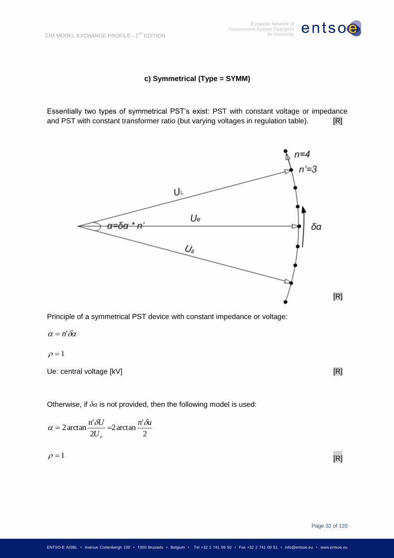
U = u * US PhaseTapChanger.voltageStepIncrementOutOfPhase
note unit is [kV] [R]
u * 100 TapChanger.stepVoltageIncrement (Optional, to be
used if
PhaseTapChanger.voltageStepIncrementOutOfPhase
not available, see below); note unit is [%] [R]
n TapChanger.highStep = n (2n+1)
TapChanger.lowStep = -n (This is restricted in the
Profile to be a positive number)
TapChanger.neutralStep = 0 (n+1)
Θ PhaseTapChanger.windingConnectionAngle
(multiple of 30°: -90, -60, -30, 0, 30, 60, 90…)
PhaseTapChangerType = “asymmetrical”
PhaseTapChanger.xStepMax (Optional - from no-
load losses) [R]
PhaseTapChanger.xStepMin (Optional - from no-
load losses) [R]
RegulatingContol.discrete = true
If the TapChanger is an asymmetrical “PhaseTapChanger” in the profile, there are three
extra required attributes and two extra optional attributes. [R]
TapChanger
PhaseTapChanger:
+PhaseTapChanger.windingConnectionAngle
+PhaseTapChangerType = "asymmetrical"
+PhaseTapChanger. voltageStepIncrementOutOfPhase
+PhaseTapChanger.xStepMax (Optional)
+PhaseTapChanger.xStepMin (Optional) [R]
Page 31
Page 31 of 120
ENTSO-E AISBL • Avenue Cortenbergh 100 • 1000 Brussels • Belgium • Tel +32 2 741 09 50 • Fax +32 2 741 09 51 • [email protected] • www.entsoe.eu
European Network of Transmission System Operators
for Electricity
CIM MODEL EXCHANGE PROFILE - 1ST
EDITION
b) Asymmetrical, = 90° (TYPE = ASYM)
Principle of an asymmetrical PST device
The adjective “asymmetrical” derives from the fact that UL is greater than US if n’≠0. The
angle between source and load voltage is given by:
)'arctan( un
The transformation ratio is given by:
1)'(
1
2
un
Page 32
Page 32 of 120
ENTSO-E AISBL • Avenue Cortenbergh 100 • 1000 Brussels • Belgium • Tel +32 2 741 09 50 • Fax +32 2 741 09 51 • [email protected] • www.entsoe.eu
European Network of Transmission System Operators
for Electricity
CIM MODEL EXCHANGE PROFILE - 1ST
EDITION
c) Symmetrical (Type = SYMM)
Essentially two types of symmetrical PST’s exist: PST with constant voltage or impedance
and PST with constant transformer ratio (but varying voltages in regulation table). [R]
Principle of a symmetrical PST device with constant impedance or voltage:
'n
1
Ue: central voltage [kV] [R]
Otherwise, if δα is not provided, then the following model is used:
2
'arctan2
2
'arctan2
un
U
Un
e
1 [R]
[R]
Page 33
Page 33 of 120
ENTSO-E AISBL • Avenue Cortenbergh 100 • 1000 Brussels • Belgium • Tel +32 2 741 09 50 • Fax +32 2 741 09 51 • [email protected] • www.entsoe.eu
European Network of Transmission System Operators
for Electricity
CIM MODEL EXCHANGE PROFILE - 1ST
EDITION
n’ SvTapStep.continuousPosition (n+1+n1)
Δα PhaseTapChanger.stepPhaseShiftIncrement
note unit is [deg] [R]
U
used if δα not
given
PhaseTapChanger.voltageStepIncrementOutOfPhase (optional,
to be used if PhaseTapChanger.stepPhaseShiftIncrement is not
available)
note unit is [kV] [R]
u * 100
used if neither
δα or U are
given
TapChanger.stepVoltageIncrement (optional, to be used if
neither PhaseTapChanger.stepPhaseShiftIncrement or
PhaseTapChanger.voltageStepIncrementOutOfPhase are
available)
When U is positive the angle is +90 and when U is negative the angle
is -90)
note unit is [%] [R]
N TapChanger.highStep = n (2n+1)
TapChanger.lowStep = -n (This is restricted in the Profile to be
a positive number)
TapChanger.neutralStep = 0 (n+1)
PhaseTapChangerType = “symmetrical”
PhaseTapChanger.xStepMax (Optional - from no-load losses)
[R]
PhaseTapChanger.xStepMin (Optional - from no-load losses)
[R]
RegulatingContol.discrete = true
If the TapChanger is a “PhaseTapChanger” in the profile, there are two extra required
attributes and two extra optional attributes. [R]
TapChanger
PhaseTapChanger:
+PhaseTapChangerType = "symmetrical"
+PhaseTapChanger.stepPhaseShiftIncrement
+PhaseTapChanger.xStepMax (Optional)
+PhaseTapChanger.xStepMin (Optional) [R]
Page 34
Page 34 of 120
ENTSO-E AISBL • Avenue Cortenbergh 100 • 1000 Brussels • Belgium • Tel +32 2 741 09 50 • Fax +32 2 741 09 51 • [email protected] • www.entsoe.eu
European Network of Transmission System Operators
for Electricity
CIM MODEL EXCHANGE PROFILE - 1ST
EDITION
4.3.2 EXPLANATION OF THE NEW PARAMETERS (XSTEPMIN, XSTEPMAX)
4.3.2.1 SYMMETRICAL PHASE SHIFTER
2
max
minmaxmin2/sin
2/sin
n
n XXXX [R]
Where:
Xn: reactance for current tap step n
αn: angle for current tap step n
Xmin, Xmax: minimum and maximum reactance of the phase shifter
αmax: maximum angle of the phase shifter
max
V1 V2 VR
Page 35
Page 35 of 120
ENTSO-E AISBL • Avenue Cortenbergh 100 • 1000 Brussels • Belgium • Tel +32 2 741 09 50 • Fax +32 2 741 09 51 • [email protected] • www.entsoe.eu
European Network of Transmission System Operators
for Electricity
CIM MODEL EXCHANGE PROFILE - 1ST
EDITION
4.3.2.2 QUADRATIC BOOSTER
2
max
max
minmaxmincostansin
costansin
tan
tan
n
n
n XXXX
[R]
Where:
Xn, αn, Xmin, Xmax, αmax: same as previous formula
Θ: winding connection angle of the phase shifter
4.3.3 EXAMPLES
4.3.3.1 DERIVATION OF THE PARAMETERS OF THE RONDISSONE TRANSFORMER
All the parameters needed in the UCTE DEF - ASCII format are derived from the no-load and
short-circuit test report.
In the following table,
u(n’) and (n’) are derived from the no-load report;
R(n’) and X(n’) are derived from the short-circuit report
max
V1
V’1
Page 36
Page 36 of 120
ENTSO-E AISBL • Avenue Cortenbergh 100 • 1000 Brussels • Belgium • Tel +32 2 741 09 50 • Fax +32 2 741 09 51 • [email protected] • www.entsoe.eu
European Network of Transmission System Operators
for Electricity
CIM MODEL EXCHANGE PROFILE - 1ST
EDITION
according to the following equations:
Remarks:
There are three central taps (0a, 0b and 0c).
The angle is given in the column “calculated [°]”.
For the simplified modelling,
Page 37
Page 37 of 120
ENTSO-E AISBL • Avenue Cortenbergh 100 • 1000 Brussels • Belgium • Tel +32 2 741 09 50 • Fax +32 2 741 09 51 • [email protected] • www.entsoe.eu
European Network of Transmission System Operators
for Electricity
CIM MODEL EXCHANGE PROFILE - 1ST
EDITION
Table: Derivation of the parameters from the Rondissone PST test report
4.3.3.2 SIMULTANEOUS PHASE AND QUADRATURE REGULATION
The Figure below shows the principle of an asymmetrical PST device with both phase and
quadrature regulation. The indices l and q pertain to in-phase and quadrature regulation
respectively. Such a PST device is installed in Gronau.
Page 38
Page 38 of 120
ENTSO-E AISBL • Avenue Cortenbergh 100 • 1000 Brussels • Belgium • Tel +32 2 741 09 50 • Fax +32 2 741 09 51 • [email protected] • www.entsoe.eu
European Network of Transmission System Operators
for Electricity
CIM MODEL EXCHANGE PROFILE - 1ST
EDITION
The angle between source and load voltage is given by:
The transformation ratio is given by:
Page 39
Page 39 of 120
ENTSO-E AISBL • Avenue Cortenbergh 100 • 1000 Brussels • Belgium • Tel +32 2 741 09 50 • Fax +32 2 741 09 51 • [email protected] • www.entsoe.eu
European Network of Transmission System Operators
for Electricity
CIM MODEL EXCHANGE PROFILE - 1ST
EDITION
4.3.3.3 DERIVATION OF THE PARAMETERS OF THE MEEDEN TRANSFORMER
All the parameters needed in the UCTE DEF – ASCII format are derived from the no-load
and short-circuit test report.
In the following table,
u(n’) and (n’) are derived from the no-load report;
R(n’) and X(n’) are derived from the short-circuit report
according to the following equations:
Page 40
Page 40 of 120
ENTSO-E AISBL • Avenue Cortenbergh 100 • 1000 Brussels • Belgium • Tel +32 2 741 09 50 • Fax +32 2 741 09 51 • [email protected] • www.entsoe.eu
European Network of Transmission System Operators
for Electricity
CIM MODEL EXCHANGE PROFILE - 1ST
EDITION
Table: Derivation of the parameters from the Meeden PST test report:
Remarks:
U is derived from measured because it is not included in the test report.
The angle is given in the column “
For the simplified modelling,
Page 41
Page 41 of 120
ENTSO-E AISBL • Avenue Cortenbergh 100 • 1000 Brussels • Belgium • Tel +32 2 741 09 50 • Fax +32 2 741 09 51 • [email protected] • www.entsoe.eu
European Network of Transmission System Operators
for Electricity
CIM MODEL EXCHANGE PROFILE - 1ST
EDITION
4.3.4 REMARKS
Remarks on the regulated transformers concerning the ideal ratio:
A 90° PST can be either symmetrical or asymmetrical. Other out-of-phase ratios are
always symmetrical. Thus, symmetrical is rather an exception that could be indicated
with a simple 'flag'. Such a flag can also be used to indicate if the ratio is due to a
simple tapping or belongs to a separate tap-changing transformer or a 'black box'.
Remarks on the tap-changer impedance:
The majority of the Swiss regulated transformers have a separate tap-changing
transformer (TCT) that is connected with a fix 3-winding transformer to form a
connected group with an angle that is zero or a multiple of +-30°. The separate TCT is
also tested individually without the main transformer. Thus, it has an individual test
report from which an impedance table is calculated. For each tap position an
impedance value is calculated which is zero for the neutral position. These tables are
used by the state estimator and in order to reconstruct an estimated case with the
help of CIM TC_tables must be an option in the same manner as the TT tables of the
UCTE DEF – ASCII format. However, all the values of the TT table must be zero in
the neutral position.
It should be possible
for three-winding transformers to have tap on-load regulation on the side "TO", means
lower voltage
(example in kV: U1/U2/U3 = 400/121/10.5 - From=400, To=121, Tert=10.5)
for two-winding step-up transformers to have regulation on the side "FROM", means
higher voltage
(example in kV: U1/U2 = 242/15.75 - From=242, To=15.75)
4.4 VOLTAGE OR ACTIVE POWER REGULATION
To use CIM to define how a piece of equipment regulates a point in the system, an
association is defined between the regulating conducting equipment (SynchronousMachine,
ShuntCompensator, or TapChanger) and an instance of RegulatingControl. The
RegulatingControl must be associated with a Terminal. The RegulatingControl for a piece of
regulating equipment can refer to a Terminal associated with another
PowerSystemResource. For instance for voltage regulation purposes, the RegulatingControl
for a SynchronousMachine could refer to a Terminal associated with a BusbarSection. The
Terminal defines the point of regulation. The association between RegulatingControl and
Terminal is required to define regulation of voltage or active power. For a
SynchronousMachine, ShuntCompensator or TapChanger that is not regulating, the
association to RegulatingControl is not required.
Page 42
Page 42 of 120
ENTSO-E AISBL • Avenue Cortenbergh 100 • 1000 Brussels • Belgium • Tel +32 2 741 09 50 • Fax +32 2 741 09 51 • [email protected] • www.entsoe.eu
European Network of Transmission System Operators
for Electricity
CIM MODEL EXCHANGE PROFILE - 1ST
EDITION
4.5 MODELLING AUTHORITIES
For purposes of data exchange, the use of explicit associations between
ModelingAuthoritySets and the objects in the model would create an unnecessary burden
because of the potential file sizes and additional processing necessary. To avoid this
situation, when using ModelingAuthoritySets, a single file must contain only data objects
associated with a single ModelingAuthoritySet.
4.6 USE OF CURVES
The use of the Curve and CurveData attributes will differ for the different types of curves
derived from Curve. A curve should never have multiple instances of CurveData where the
xvalue value is repeated.
4.6.1 GENERATING UNIT REACTIVE POWER LIMITS
Generating unit reactive power limits must be included in data exchange, but may be
specified differently depending on the characteristics of the generating unit being
represented. In most cases, a SynchronousMachine should be associated with a default
ReactiveCapabilityCurve using the SynchronousMachine.InitiallyUsesMVArCapabilityCurve
association.
If the reactive power limits of the generating unit do not vary with the real power output, the
reactive power limit attributes on the SynchronousMachine class, minQ and maxQ, can be
used. If the reactive power output of the generating unit is fixed, the reactive power limits
should both be set to the fixed reactive output value.
Page 43
Page 43 of 120
ENTSO-E AISBL • Avenue Cortenbergh 100 • 1000 Brussels • Belgium • Tel +32 2 741 09 50 • Fax +32 2 741 09 51 • [email protected] • www.entsoe.eu
European Network of Transmission System Operators
for Electricity
CIM MODEL EXCHANGE PROFILE - 1ST
EDITION
5 ENTSO-E PROFILE NOTES
This section describes changes, issues, and areas of potential confusion based on producing
the detailed profile given in Chapter 6.
5.1 CIMTOOL PROFILE PROPERTIES
The profile is based upon a specific CIM UML version from
iec61970cim14v02_ucte20080204.eap, but the tooling makes it easy to migrate a profile
definition from one compatible UML version. The namespace used for the CIM UML model is
compatible with that used for the CIM IOP in the past several years. The UML namespace is
http://iec.ch/TC57/2009/CIM-schema-cim14#. This namespace will appear in the RDFids
artifacts generated by CIMTool. Validators will likely assume an exact match with this
namespace and the attributes used in the CIM/RDF/XML instance files (typically by defining
the “cim” namespace the same as the above namespace string.
The namespace for the profile itself is presently chosen to be http://entsoe.eu/2009/profile1#
and this is one way to easily identify the profile version in CIMTool. Additionally, profile
specific notes have been added to the IEC61970CIMVersion class as a convenient way of
putting notes on the profile. CIMTool does not yet have a way to attach user notes directly to
a profile, but notes can be attached to any class.
There are only a few classes with profile specific CIMTool notes and all these notes will
appear in the HTML output of CIMTool and hence appear in the official profile document.
Additionally, the UML (iec61970cim14v02_ucte20080204.eap) contains some “UCTE”
stereotypes on UML components (such as attributes on existing standard CIM classes) that
were specific for UCTE at the time when the profile was generated.
5.2 X-NODE CONTAINMENT ISSUES
This topic will not address the ModelingAuthoritySet issues related to X-nodes. The text
represents the summary of several previous discussions and decisions made at the Brussels
workshop on January 20, 2009. X-nodes are primarily modelled as cim:TopologicalNode
objects.
A cim:EnergyConsumer object is specified as part of the solution output to hold the flow
through the line to the X-node. Each modelling authority would model cases that connect a
cim:ACLineSegement to the X-node cim:TopologicalNode and also connect to an internal
cim:TopologicalNode. EnergyConsumers connected to X-Nodes and X-Node should be
marked with EquivalentFlag set to True.
The TopologicalNode objects are normally contained within a cim:VoltagelLevel, but in the
case of X-node instances at the center of a tie line, the TopologicalNode has no containment.
Page 44
Page 44 of 120
ENTSO-E AISBL • Avenue Cortenbergh 100 • 1000 Brussels • Belgium • Tel +32 2 741 09 50 • Fax +32 2 741 09 51 • [email protected] • www.entsoe.eu
European Network of Transmission System Operators
for Electricity
CIM MODEL EXCHANGE PROFILE - 1ST
EDITION
Line containment is not used to hold the TopologicalNode either because Line class has
been removed from profile. The base voltage can be obtained using the direct association
end of cim:TopologicalNode.BaseVoltage.
The ENTSO-E format requires no association of line to a geographical region.
The TopologicalNode representing the X-node will not be contained in any container.
5.3 TRANSFORMER MAPPING CLARIFICATION
A cim:PowerTransformer maps to a Transformer record in the UCTE DEF - ASCII format.
For a two winding transformer, two cim:TransformerWinding objects are created. For a three
winding transformer, three cim:TransformerWinding objects are created. Presumably, there
is a convention of zero or blank for “Node3 ID” to indicate a two or three winding transformer.
The “delta” impedances in the UCTE DEF - ASCII format can be translated to the CIM “star”
impedances stored on transformer windings. This works with well-known formulas for
transforming the series impedances in cim:TransformerWinding.r and
cim:TransformerWinding.x, but the shunt or no-load impedances are discussed in a separate
issue.
5.4 TRANSFORMER NO LOAD LOSSES ISSUE
The transformer no load losses are modelled within the cim:TransformerWinding.g attribute.
This is the shunt conductance to ground and would therefore generate no load losses. There
are multiple ways to map no-load losses into the shunt terms on the cim:TransformerWinding
objects, though the effect of putting this shunt on one terminal or another is likely very small
for steady-state power flow. There could be some meaningful impact on short circuit.
Specifically this is the ENTSO-E Transformers B and G attributes and how they map to the
cim:TransformerWinding.b and cim:TransformerWinding.g attributes on the multiple
cim:TransformerWinding objects (one for each terminal, for example primary and secondary).
The most simple answer is to simply split it equally to cim:TransfromerWinding objects for a
cim:PowerTransformer. Going from CIM to UCTE DEF - ASCII format would just sum them
together for a cim:PowerTransformer.
5.5 TRANSFORMER REGULATION MAPPINGS
The CIM14 UML requires zero or one RatioTapChanger objects associated to a
TransformerWinding. The CIM14 UML requires zero or one PhaseTapChange objects
associated to a TransformerWinding. Normally, voltage magnitude transformers would model
one RatioTapChanger unless they are fixed tap. A phase shifter would normally only model
one PhaseTapChanger and no RatioTapChanger. In the case there are two separate taps,
one only changing ratio and one changing phase. It is possible to model both a
RatioTapChanger and a PhaseTapChanger for one transformer. Note that a
Page 45
Page 45 of 120
ENTSO-E AISBL • Avenue Cortenbergh 100 • 1000 Brussels • Belgium • Tel +32 2 741 09 50 • Fax +32 2 741 09 51 • [email protected] • www.entsoe.eu
European Network of Transmission System Operators
for Electricity
CIM MODEL EXCHANGE PROFILE - 1ST
EDITION
PhaseTapChanger object can optionally have voltage ratio effects depending upon the type
of phase shifter.
5.6 REGULATINGCONTROL MAPPINGS
Any sort of regulation control goes through a RegulatingControl object. Thus any device that
regulates must also model an associated RegulatingControl object. The RegulatingControl
object can allow for multiple devices participating in regulating one quantity, but ENTSO-E
should likely restrict this capability to single devices performing independent regulation as
this normal current practice. Power flow implementations can and must resolve multiple
devices regulating the same quantity. For example, a power flow implementation can
recognize that two SynchronousMachines are both regulating the same TopologicalNode at
the high side of their respective transformers and appropriately handle the situation.
The RegulatingControl class contains various options for types of regulation. Some
combinations of specifying impedance regulation for a SynchronousMachine may not make
sense. A definition of the sensible combinations is probably needed, but there is likely to be
little confusion on this among power flow users. Validation rules could be helpful here.
5.7 STATICVARCOMPENSATOR INCLUSION QUESTION
It is agreed to remove StaticVarCompensator (SVC) from the profile. SVC should be properly
modelled and included in CIM for Dynamics profile which will be an extension of this profile.
5.8 EQUIVALENT FLAG ON REAL MODELS ISSUE
ENTSO-E has resolved to identify equivalents within the model with an ENTSO-E specific
Boolean flag added to the Equipment class. This is likely not the direction of CIM equivalents
modeling in the future, but was deemed appropriate for immediate ENTSO-E needs. The
real/equivalent status is not specified on the TransformerWinding since it is specified on the
PowerTransformer. For all other classes derived from Equipment, the Equipment.equivalent
flag is to be included in exchange files and specifically exchanged with a value of true or
false. If the value is blank it is assumed to be False. A note is included in the CIMTool profile.
This ENTSO-E profile includes the “equivalent” attribute on the TopologicalNode class. The
semantic description of the attribute may need further clarification, but the mapping to the
UCTE DEF – ASCII format is clear.
5.9 TRANSFORMER STEP IMPEDANCE MODELS ISSUE
Profile and UML do not contain this.
5.10 NAMING CONVENTIONS AND USE OF IDENTIFIEDOBJECT
There is no compelling reason to complicate naming with localName. All references to
localName in the ENTSO-E profile have been removed. Any specific identification must rely
upon using the complete name specified in the attribute Name. Naming rules for uniqueness
Page 46
Page 46 of 120
ENTSO-E AISBL • Avenue Cortenbergh 100 • 1000 Brussels • Belgium • Tel +32 2 741 09 50 • Fax +32 2 741 09 51 • [email protected] • www.entsoe.eu
European Network of Transmission System Operators
for Electricity
CIM MODEL EXCHANGE PROFILE - 1ST
EDITION
of “circuit number” are into Name – name is unique in case of parallel elements. In general,
the circuit number is an artifact of the limitations of the text exchange format or various
implications in the connectivity model. No such limitations exist in CIM.
The name attribute on IdentifiedObject class is normally required. If this practice is continued,
there would be some places where names do not make sense and artificial names would
need to be created. For example, items like RatioTapChanger would need a name since it
inherits from IdentifiedObject. For this reason, the Name attribute is optional in this profile.
The Name attribute is limited to the generic length specified in the profile. The description
and name have no functional purpose and are for human consumption.
The IdentifiedObject.aliasName is used to hold the EIC code (EIC – a code issued by the
former association ETSO; now these codes are issued and maintained by ENTSO-E). The
aliasName is optional in the profile to support specifying this only where appropriate. The
aliasName should be used only for EIC codes in this profile.
Additional details surrounding the ENTSO-E Naming Conventions are provided in Appendix
A.
5.11 TERMINAL CONNECTED EXPLANATION
The cim:Terminal.connected attribute is the means to express weather a terminal of any
equipment is connected or disconnected. This allows for the basic topology of the system to
remain defined, yet specific equipment to be disconnected in a power flow solution sense.
Since we are not modelling the internal state of most switches in the ENTSO-E model, the
effect of those switches is expressed in the cim:Terminal.connection status. The terminal
connection status says nothing about equipment being energized other than equipment
whose terminals are all marked disconnected would obviously not be energized. It is possible
for one terminal of a branch to be connected and the other terminal not connected. Even the
retained cim:Switch objects are to be expressed as open or closed only via the
cim:Terminal.connected attributes. If the switch itself is open, both terminals would have
cim:Terminal.connected as false. If the switch itself is closed, the terminals may or may not
be closed depending upon the state of other, missing from ENTSO-E profile, detailed
modelling of not retained switches, for example disconecters in series with the switch.
To determine the availability of the Generator (1 for in service and 0 for out of service), the
actual connection status should be on the cim:Terminal.connected attribute of the
cim:SynchronousMachine.
5.12 GENERATINGUNIT SUBTYPES ISSUE
The GeneratingUnit class is subtyped to indicate what type of generating unit. ENTSO-E has
various generator types and they map to CIM classes generally.
H = cim:HydroGeneratingUnit with no HydroPump
Page 47
Page 47 of 120
ENTSO-E AISBL • Avenue Cortenbergh 100 • 1000 Brussels • Belgium • Tel +32 2 741 09 50 • Fax +32 2 741 09 51 • [email protected] • www.entsoe.eu
European Network of Transmission System Operators
for Electricity
CIM MODEL EXCHANGE PROFILE - 1ST
EDITION
P = cim:HydroGenrartingunit with HydroPump
N = cim:NuclearGeneratingUnit
L = cim:ThermalGeneratingUnit – Use FossilFuel.fossilFuelType of enum value
“lignite”
C = cim:ThermalGeneratingUnit – Use FossilFuel.fossilFuelType of enum value “coal”
G = cim:ThermalGeneratingUnit – Use FossilFuel.fossilFuelType of enum value “gas”
O = cim:ThermalGeneratingUnit – Use FossilFuel.fossilFuelType of enum value “oil”
W = cim:WindGeneragtingUnit
F = cim:GeneratingUnit – CIMTool profile has marked this as a concrete class
The ThermalGeneratingUnit as a required association of FossilFuels which in the profile is
restricted to 1..1 so one FossilFuel object is created for each ThermalGeneratingUnit. The L,
C, G, O types in the UCTE DEF - ASCII format map directly to the FossilFuel.fossilFuelType
enumeration values of “lignite”, “coal”, “gas” and “oil”.
5.13 LIMIT TYPE ISSUE
Some examples were put into the mapping Excel document. ENTSO-E has selected to
exchange current limits only. If other limit types are used, they will need to be translated to
participate in ENTSO-E exchanges.
Note ENTSO-E choice for the normative names follow the “==” and are enclosed in quotes.
"high voltage limit" on node == “HighVoltage”
"low voltage limit" on node == “LowVoltage”
Since the terminal assignment is always explicitly exchanged as
OperationalLimitSet.Terminal and given that we are now exchanging a
Terminal.sequenceNumber.
ENTSO-E will use the concept of NULL exchanged as an empty value in the RDF/XML, but
that is not a standard, though it works with incremental updates.
The OperationalLimitType.direction is absolute value
(OperationalLimitDirectionKind.absoluteValue) for all OperatonalLimitType objects except the
high (OpeationalLimitDirectionKind.high) and low (OperationalLimitDirectionKind.low) voltage
limits.
Both terminals are to be specified and the profile need not change. Only one limit of each
type can be specified for each end of each branch. The PATL limits must be specified for all
Transformers and at both ends of the ACLineSegment. All other limit types must be
Page 48
Page 48 of 120
ENTSO-E AISBL • Avenue Cortenbergh 100 • 1000 Brussels • Belgium • Tel +32 2 741 09 50 • Fax +32 2 741 09 51 • [email protected] • www.entsoe.eu
European Network of Transmission System Operators
for Electricity
CIM MODEL EXCHANGE PROFILE - 1ST
EDITION
supported. If any other limit type is included, then both ends should be included. All limit
types defined in the Profile can be required to be exchanged together in case of a specific
business process. There is no optimization for the use of identical limits at both ends of the
line, though this could be added later.
To further explain the above statements, the following should be noted:
At least one of the limit types must be provided (this is the minimum requirement)
All types of limits are exchanged (at the same time) if required by the specific
exchange process, which could change depending on the business use for the
exchanged files.
For operations, the parties involved in the exchange need to clearly define what limit
types will be included in the exchange.
I1 - Permanent Admissible Transmission Loading (PATL). The Permanent Admissible
Transmission Loading (PATL) is the loading in Amps, that can be accepted by a network
branch for an unlimited duration without any risk for the material. Create one instance of
cim:OperationalLimitType with name "PATL" and acceptableDuration of NULL (empty in
RDFS). NULL means infinite duration.
T1 - Alarm threshold in N state = X% of I1. Similar to above with one more CurrentLimit
assigned to (global) OpeationalLimitType with name of "Alarm", and acceptableDuration
NULL.
I3 - Tripping Current (TC). An ultimate intensity, called the Tripping Current without delay
(TC), is defined as the threshold the line will trip without any possible remedial actions. The
tripping of the network element is ordered by protections against short circuits or by overload
protections, but in any case, the activation delay of these protections is not compatible with
the reaction delay of an operator (less than one minute). OperationalLimitType of
"TrippingCurrent".
T3 - Instantaneous tripping threshold to be considered for calculations; it takes into account a
margin from I3. OperationalLimitType of "WarningTrippingCurrent".
I2k - Temporary Admissible Transmission Loading (TATL). Some TSOs use a Temporarily
Admissible Transmission Loading which is the loading in Amps that can be accepted by a
branch for a certain limited duration. The TATL can be defined in different ways:
as a fixed percentage of the PATL for a given time (for example, 115% of the PATL
can be accepted during 15 minutes),
several specific couples (TATL; Duration) are calculated for each line taking into
account its particular configuration and conditions of functioning (for example, it can
be defined a TATL acceptable during 20 minutes and another one acceptable during
10 minutes).
Page 49
Page 49 of 120
ENTSO-E AISBL • Avenue Cortenbergh 100 • 1000 Brussels • Belgium • Tel +32 2 741 09 50 • Fax +32 2 741 09 51 • [email protected] • www.entsoe.eu
European Network of Transmission System Operators
for Electricity
CIM MODEL EXCHANGE PROFILE - 1ST
EDITION
Such a definition of TATL can depend on the initial operating conditions of the network
element (sag situation of a line).
Corresponding to D2k; k=0-n. OperationalLImitType with name "TATLk" where the k is an
integer formatted as text. For example starting with TATL1, TATL2, ..TATL99 There is no
upper limit to k.
D2k - acceptable duration corresponding to I2k; k=0-n
5.14 MAPPING OF SOLVED STATE TO INJECTION VALUES
The profile includes no “starting” injection values for loads (cim:EnergyConsumer) or
generators (cim:SynchronousMachine). To initialize a power flow from a starting point, power
flow implementations typically have a starting injection value or a “base” injection value at a
load point. The ENTSO-E separates these injection values from the “target and range”
values associated with regulation control. The power flow input is both the target regulation,
the “fixed” injections and starting values for state variables that are solved, such as voltages.
The load injections at nominal voltage can be computed from the solved state stored on
cim:SvPowerFlow associated to the cim:EnergyConsumerTerminal and the known load
response characteristics (on cim:LoadResponseCharacteristic).
The voltage exponent models are fairly simple and only used when the
cim:LoadResponseCharacteristic.exponentModel is true.
Page 50
Page 50 of 120
ENTSO-E AISBL • Avenue Cortenbergh 100 • 1000 Brussels • Belgium • Tel +32 2 741 09 50 • Fax +32 2 741 09 51 • [email protected] • www.entsoe.eu
European Network of Transmission System Operators
for Electricity
CIM MODEL EXCHANGE PROFILE - 1ST
EDITION
The “P solved” below is available on the cim:SvPowerFlow.p attribute tied to the
cim:Terminal of interest.
The “P base” is internal implementation of a power flow application. Though it is likely to be
added to CIM in case you want to exchange power flow setup without a solved case, but that
is not the ENTSO-E needs.
The V is in terms of a per unit voltage here, so the nominal voltage must be known, but that
is readily available via the association from Terminal to TopologicalNode and then
TopologicalNode to VoltageLevel then VoltageLevel to BaseVoltage where the floating value
of base voltage is stored.
P solved = P base * V magnitude ** exponent
So,
P base = Psolved / (V magnitude ** exponent)
The case for the ZIP (impedance/current/power) load model when
cim:LoadResponseCharacteristic.exponentModel equals false is only slightly harder.
By definition of CIM:
P solved = Pbase (A*V**2 + B *V + C)
Where
A = cim:LoadResponseCharacteristic.pConstantImpedance
B = cim:LoadResponseCharacterisitc.pConstantCurrent
C = cim:LoadResponseCharacteristic.pConstantPower
Note A, B and C are all of type Float and are scalers of the base power which would be typed
as cim:ActivePower. CIM14 will likely add this base power for EnergyConsumer, but it is
easy to compute if given voltage and solved injection.
One might consider the case where A==B==C==0 but this is probably invalid model and
could mean pBase is always zero instead of undefined.
For ENTSO-E, if LoadResponseCharacteristic.exponentModel is True, the voltage exponents
are specified and used as:
cim:SvPowerFlow.p = Pnominal * (cim:SvVoltage.v / cim:BaseVoltage.nominalVoltage)**
cim:LoadResponseCharacteristic.voltageExponent. Where * means multiply and ** means
“raised to the power of”.
For generators it is even simpler. The only real unknown is the starting point of the slack
generator injections. This is not exchanged. The starting point is assumed to be from the
Page 51
Page 51 of 120
ENTSO-E AISBL • Avenue Cortenbergh 100 • 1000 Brussels • Belgium • Tel +32 2 741 09 50 • Fax +32 2 741 09 51 • [email protected] • www.entsoe.eu
European Network of Transmission System Operators
for Electricity
CIM MODEL EXCHANGE PROFILE - 1ST
EDITION
solved point. Generators with fixed reactive power, would simply hold the solved value. For
fixed power injection generators (non-slack) the solved value equals the starting value.
Similarly the starting value for taps moving for regulation control can start at the solved value
and taps not moving are fixed at the solved value.
Similar for ShuntCompensator steps.
5.15 SHUNTCOMPENSATOR SWITCHING AND TERMINAL CONNECTION
ISSUE
For a ShuntCompensator instance with Terminal.connected attribute set “false”, the following
applies:
The ShuntCompensator is assumed to be disconnected and unavailable for use in a
power flow solution. This is the way to communicate that the device is out for
maintainence in some manner.
The associated SvShuntCompensatorSections.sections and
SvShuntCompensatorSections.continuousSections attributes and the regulation
mode on any associated RegulatingControl are not relevant in a power flow solution
since the device is not connected and cannot be connected by a power flow solution.
The actual injection in a power flow solution is zero and cannot change during a
simple power flow solution.
A ShuntCompensator that is in service regulating voltage but switched off, should have the
Terminal.connected status set to “true”. The associated SvShuntCompensator.sections (and
continuousSections) can have any value within the valid range for this ShuntCompensator
including the zero value.
A ShuntCompensator with Terminal.connected “true” will inject power appropriately for the
specification on the associated SvShuntCompensatorSections instance. In the case of no
RegulatingControl or a RegulatingControl with RegulatingControl.mode of “fixed”, the number
of sections will not change and the Terminal.connected status will not be changed by a
powerflow solution.
5.16 LINE ENDS FOR MUTUALCOUPLING ISSUE
This profile and standard IEC61970-452 do not distinguish the terminal connection directions
of a branch. Thus in CIM, the directional orientation of a line is lost, though it is physically
modelled correctly. The MutualCouplings class as it exists requires a “starting” end of an
ACLineSegment from which to compute distance.
It was proposed to make the model explicit with the change so that MutualCoupling would
point to a terminal and thus not require any directional sense of the line. This had the
advantage of not requiring a change related to Terminal attributes, but also the disadvantage
Page 52
Page 52 of 120
ENTSO-E AISBL • Avenue Cortenbergh 100 • 1000 Brussels • Belgium • Tel +32 2 741 09 50 • Fax +32 2 741 09 51 • [email protected] • www.entsoe.eu
European Network of Transmission System Operators
for Electricity
CIM MODEL EXCHANGE PROFILE - 1ST
EDITION
of potentially meaningless connections between MutualCoupling and terminals of a
SynchronousMachine for example. The existing MutualCoupling model links directly to
ACLineSegement and thus does not require special validation given that Terminal
connection directions are available.
The terminal sequence applies to all devices, even shunts. Transformer direction uses
primary and secondary specifications; 1=Primary and 2=Secondary.
Terminal.sequenceNumber is required on ACLineSegment or any Branch equipment
connections other than Transformer.
5.17 MUTUALCOUPLING IDENTIFICATION ISSUE
The MutualCoupling class needs identity for things like incremental updates and especially
cases where multiple coupling regions exist down the same two ACLineSegements.
Therefore, MutualCoupling Inherites from IdentifiedObject.
5.18 SHUNTCOMPENSATOR POSITIVE SEQUENCE IMPEDANCE PER
SECTION ISSUE
ENTSO-E added to use gPerSection. It is agreed that nomU, reactivePerSection, or
yPerSection are no longer needed.
5.19 CIMTOOL RDFS IMPROVEMENT ISSUE.
The CIMTool program has an option to reorganize and improve the profile for RDFS
generation. The effect is to move base class attributes in most cases to the underlying base
class. Such moves can effectively add attributes to other sub-classes of the base class that
may not have included the original base class attribute. An excellent example of this is the
addition of the MemberOf_EquipmentContainer to the TransformerWinding class.
5.20 READING THE CIMTOOL PROFILE HTML OUTPUT.
All abstract and base classes are added explicitly to the profile, either manually or through
the RDFS improvement button in CIMTool. The effect is that the HTML output from CIMTool
can be directly used to determine from which class each attribute is inherited. The
inheritance links in the HTML must be followed in order to do this. The basic assumption is
that no case in the profile where a specialized class uses its inherited attributes or
associations differently than from the base class. Where this is not entirely true, comments
have been added to the profile documentation of the base class attribute or association to
help clarify its proper usage. Thus you should be able to get a pretty close mapping from the
HTML output to the RDF/XML structure for an object instance in the exchange files.
Attributes and associations ends listed directly under the class, belong to that class directly.
Follow the link to the super class if it exists to get additional inherited attributes and
associations.
Page 53
Page 53 of 120
ENTSO-E AISBL • Avenue Cortenbergh 100 • 1000 Brussels • Belgium • Tel +32 2 741 09 50 • Fax +32 2 741 09 51 • [email protected] • www.entsoe.eu
European Network of Transmission System Operators
for Electricity
CIM MODEL EXCHANGE PROFILE - 1ST
EDITION
For example, on BaseVoltage class, to get the name attribute you follow the superclass link
to IdentifiedObject and see that it has an “IdentifiedObject.name” attribute and an
“IdentifiedObject.description” attribute.
For classes with deeper inheritance, you simply recursively follow the superclass links.
Note the Word document version of this might not preserve these hyperlinks, so using the
HTML output of CIMTool directly in an HTML browser might be more useful.
Note that CIMTool as of version 1.5.2 is properly documenting the UML association ends.
5.21 SVPOWERFLOW MODEL COVERAGE ISSUE.
Only Terminals of EnergyConsumer and SynchronousMachine will have SvPowerFlow
instances assigned. The number of SvPowerFlow instances in the model should match the
number of EnergyConsumer plus SynchronousMachine objects in the model regardless of
the Terminal.connected values. Any SvPowerFlow with a Terminal.connected value of “false”
must have zero flow explicitly specified on an SvPowerFlow instance. The flows on Switch
variables are not required to be exchanged.
The power is stored on the cim:SvPowerFlow.p and cim:SvPowerFlow.q attributes that are
associated with the cim:Terminal of the cim:SynchronousMachine.
The other types of terminals are not included in exchanges since their values can be readily
computed from local voltages and attributes without a global power flow solution.
5.22 GENERATINGUNIT AND SYNCHRONOUSMACHINE MULTIPLICITY
ISSUE
The GeneratingUnit and SynchronousMachine are assumed to always come in pairs in the
ENTSO-E profile. For each GeneratingUnit there is one and only one SychronousMachine
and each SynchronousMachine has an associated GeneratingUnit. In the IEC61970-452
profile it was allowed to model a synchronous condenser with no GeneratingUnit associated
or to have multiple SynchronousMachines as part of a single GeneratingUnit, but ENTSO-E
has restricted this further to a simple one to one relationship. The ENTSO-E profile maintains
the typical association end from the SynchronousMachine only for compatibility with existing
implementations that comply with the IEC61970-452 profile.
5.23 DATATYPE MULTIPLIER AND UNITS DEFAULTS ISSUE
The profile describes the default values assumed for datatype multiplier and units attributes.
These are fairly clear in most cases. The UML describes the initial value of most units for
datatype classes, however the multiplier is not defined in the UML and must be defined in the
profile.
CIMTool does not presently allow you to add profile notes on datatype classes so these need
to be added to the text.
Page 54
Page 54 of 120
ENTSO-E AISBL • Avenue Cortenbergh 100 • 1000 Brussels • Belgium • Tel +32 2 741 09 50 • Fax +32 2 741 09 51 • [email protected] • www.entsoe.eu
European Network of Transmission System Operators
for Electricity
CIM MODEL EXCHANGE PROFILE - 1ST
EDITION
ActivePower – unit = W (from UML), multiplier = M
AngleDegrees – unit = deg (from UML), multiplier = none (from UML)
AngleRadians – unit = rad (from UML), multiplier = none (from UML)
ApparentPower - unit = VA (from UML), multiplier = M
Conductance- unit = S (from UML), multiplier = none
CurrentFlow – unit = A (from UML), multiplier = none
LongLength – unit = m (from UML), multiplier = k (from UML)
Money – currency = EUR, multipier = none
PerCent – unit = none (from UML), multiplier = none (from UML)
Reactance – unit = ohm (from UML), multiplier = none
ReactivePower – unit = VAr (from UML), multiplier = M
Resistance – unit = ohm (from UML), multiplier = none
Seconds – unit = s (from UML), multiplier = none (from UML)
Suseptance – unit = S (from UML), multiplier = none
Voltage – unit = V (from UML), multiplier = k
5.24 SERIESCOMPENSATOR IS EXCLUDED FROM PROFILE
The classSeriesCompensator is excluded from the ENTSO-E profile since these can be
modeled as ACLineSegement objects.
5.25 ACTIVE POWER SLACK AND ANGLE REFERENCE
SPECIFICATIONS DESCRIPTION
The active power slack is specified by using the multiple generator slack specification in CIM.
The ENTSO-E profile, by convention, restricts the slack to a single slack point initially. For
the ENTSO-E profile, one GeneratingUnit per control area will require a non-zero
participation factor (GeneratingUnit.normalPF) while all other generating units will have a
zero participation factor. That is, the slack node is specified by a non-zero participation factor
on the GeneratingUnit.normalPF attribute. The normalPF is an optional attribute and
assumed to be zero if missing from full (not incremental) model exchanges. The specification
of the angle reference bus is not particularly critical to solution exchanges, but is referenced
by the TopologicalIsland using AngleRef_TopologicalNode association end.
Page 55
Page 55 of 120
ENTSO-E AISBL • Avenue Cortenbergh 100 • 1000 Brussels • Belgium • Tel +32 2 741 09 50 • Fax +32 2 741 09 51 • [email protected] • www.entsoe.eu
European Network of Transmission System Operators
for Electricity
CIM MODEL EXCHANGE PROFILE - 1ST
EDITION
5.26 CONTINUOUS SVSHUNTCOMPENSATORSECTIONS AND
SVTAPSTEP ISSUE
Tap step position and shunt compensator sections can be solved in either a continuous or
discrete mode as specified on the associated RegulatingControl. If in the
RegulatingControl.discrete attribute is set true, the continuous attribute
SvShuntCompensatorSections.continuousSections or SvTapStep.continuousPosition is
used, but set to a discrete value. If the RegulatingControl.discrete is “false” then the floating
point attribute SvShuntCompensatorSections.continuousSections or
SvTapStep.continuousPosition is specified as any valid floating point value. If no
RegulatingControl is associated with ShuntCompensator or TapChanger then either integer
or continuous values can be specified.
Note that the continuous attributes have a “Float” type but are semantically the same as the
discrete attributes having an “Integer” type.
The ENTSO-E profile only includes the continuous variables as they can hold either
continuous or discrete values.
6 ENTSO-E CIM MODEL EXCHANGE PROFILE
SPECIFICATION
This chapter lists both the concrete and abstract classes that are used to define data
exchange. Only instances of concrete classes are used in actual exchanges. Those concrete
classes may inherit attributes or associations from abstract classes, however. Such inherited
attributes and associations are documented.
Included are all the classes that a data consumer would be expected to recognize in the data
being consumed. Additional classes are referenced in this chapter, when the classes to be
exchanged inherit attributes or associations. For instance, many classes inherit attributes
from the class IdentifiedObject. However, no instances of the class IdentifiedObject would
exist in the data exchanged, so IdentifiedObject has not been included in the set of concrete
CIM classes for exchange.
6.1 DETAILED MAPPING OF CLASSES TO ENTSO-E FILE TYPES
The diagram provided in this section provides a conceptual drawing of the possible classes
that comprise the ENTSO-E file types. In most cases, classes are used in only one file, but
there are occasions where part of the class data is described in one file and then additional
class data is added in another. In this case, the second file is said to be “dependent” on the
first. Dependency like this may also happen simply because classes in the second file have
associations to classes in the first. In the diagram, both types of dependencies are noted with
arrows from the dependent class to the class it depends on.
Page 56
Page 56 of 120
ENTSO-E AISBL • Avenue Cortenbergh 100 • 1000 Brussels • Belgium • Tel +32 2 741 09 50 • Fax +32 2 741 09 51 • [email protected] • www.entsoe.eu
European Network of Transmission System Operators
for Electricity
CIM MODEL EXCHANGE PROFILE - 1ST
EDITION
Since the diagram in this section is a conceptual drawing, it may not represent a complete
picture of the contents for each of the files. The classes defined in the Common Objects file
(the Gray box in the diagram) are actually contained in the TSO Equipment Model file (the
Blue box in the diagram).
As shown in the diagram, the Terminal class is split between the TSO Topology file (the
Green box in the diagram) and the TSO Equipment file. In the TSO Topology file, the “about”
RDF syntax is used to connect the Terminal in both files. The Terminal class in the TSO
Topology file uses only the Terminal.connected attribute and the “about” syntax identifies
which Terminal it correlates to in the TSO Equipment file. The Terminal in the TSO
Equipment file uses all the Terminal attributes except the Terminal.connected attribute. The
Terminal in the TSO Topology file is connected to the SvPowerFlow and this defines if the
flow can be supported. Only Terminal instances of EnergyConsumers and
SynchronousMachines will have SvPowerFlow instances assigned. A terminal that is
connected (the Terminal.connected attribute is “True”) can support a flow.
To provide clarity the lists below define the set of classes that are contained in each of the
three files that will be used by ENTSO-E.
The State Variables file may contain the following classes:
SvPowerFlow
SvVoltage
SvTapStep
SvShuntCompensatorSections
The TSO Topology file may contain the following classes:
TopologicalNode
TopologicalIsland
Terminal (about)
The TSO Equipment file may contain the following Concrete classes:
ACLineSegment
BaseVoltage
ControlArea
ControlAreaGeneratingUnit
CurrentLimit
Page 57
Page 57 of 120
ENTSO-E AISBL • Avenue Cortenbergh 100 • 1000 Brussels • Belgium • Tel +32 2 741 09 50 • Fax +32 2 741 09 51 • [email protected] • www.entsoe.eu
European Network of Transmission System Operators
for Electricity
CIM MODEL EXCHANGE PROFILE - 1ST
EDITION
CurveData
EnergyConsumer
FossilFuel
GeneratingUnit (subtypes of this class should be used in the exchange if known)
GeographicalRegion
HydroGeneratingUnit (subtype of GeneratingUnit)
HydroPump
IEC61970CIMVersion
LoadResponseCharacteristic
MutualCoupling
NuclearGeneratingUnit (subtype of GeneratingUnit)
OperationalLimitSet
OperationalLimitType
PhaseTapChanger
PowerTransformer
RatioTapChanger
ReactiveCapabilityCurve
RegulatingControl
ShuntCompensator
SubGeographicalRegion
Substation
Switch
SynchronousMachine
Terminal
ThermalGeneratingUnit (subtype of GeneratingUnit)
TieFlow
Page 58
Page 58 of 120
ENTSO-E AISBL • Avenue Cortenbergh 100 • 1000 Brussels • Belgium • Tel +32 2 741 09 50 • Fax +32 2 741 09 51 • [email protected] • www.entsoe.eu
European Network of Transmission System Operators
for Electricity
CIM MODEL EXCHANGE PROFILE - 1ST
EDITION
TransformerWinding
VoltageLevel
VoltageLimit
WindGeneratingUnit (subtype of GeneratingUnit)
State Variables
TSO Topology
TSO Equipment Model
ACLineSegment
ControlArea
CurrentLimit
CurveData
EnergyConsumer
FossilFuel
GeneratingUnit
GeographicalRegion
HydroGeneratingUnit
HydroPump
MutualCoupling
NuclearGeneratingUnit
OperationalLimitSet
PhaseTapChanger
PowerTransformer
RatioTapChanger
ReactiveCapabilityCurve
RegulatingControl
SeriesCompensator
ShuntCompensator
SubGeographicalRegion
Substation
SvPowerFlow SvShuntCompensatorSections SvTapStepSvVoltage
Switch
SynchronousMachine
Terminal
Terminal (about)
ThermalGeneratingUnit
TieFlow
TopologicalIsland
TopologicalNode
TransformerWinding
VoltageLevel
VoltageLimit
WindGeneratingUnit
UCTE Common Objects BaseVoltage OperationalLimitType
ControlAreaGeneratingUnit
LoadResponseCharacteristic
6.2 PROFILE DOCUMENTATION
Profile namespace: http://entsoe.eu/2009/profile1#
Page 59
Page 59 of 120
ENTSO-E AISBL • Avenue Cortenbergh 100 • 1000 Brussels • Belgium • Tel +32 2 741 09 50 • Fax +32 2 741 09 51 • [email protected] • www.entsoe.eu
European Network of Transmission System Operators
for Electricity
CIM MODEL EXCHANGE PROFILE - 1ST
EDITION
6.3 CONCRETE CLASSES
IMPORTANT REMARK: References to UCTE profile in the section below are not
changed, but they have to be understood as references to ENTSO-E profile.
6.3.1 ACLINESEGMENT
Wires
A wire or combination of wires, with consistent electrical characteristics, building a single electrical system, used to carry alternating current between points in the power system.
Series compensators can be modeled as ACLineSegement. The attribute Conductor.length is required only when used in conjunction with a Mutual Coupling.
Superclass: Conductor
6.3.2 BASEVOLTAGE
Core
Collection of BaseVoltages which is used to verify that the BusbarSection.BaseVoltage and other voltage attributes in the CIM are given a value existing in the collection.
Superclass: IdentifiedObject
6.3.2.1 MEMBERS
isDC 1..1 boolean If true, this is a direct current base voltage and items assigned to this base voltage are also associated with a direct current capabilities. False indicates alternating current.
nominalVoltage 1..1 Voltage The PowerSystemResource's base voltage.
6.3.3 CONTROLAREA
ControlArea
A control area is a grouping of generating units and/or loads and a cutset of tie lines (as terminals) which may be used for a variety of purposes including automatic
Page 60
Page 60 of 120
ENTSO-E AISBL • Avenue Cortenbergh 100 • 1000 Brussels • Belgium • Tel +32 2 741 09 50 • Fax +32 2 741 09 51 • [email protected] • www.entsoe.eu
European Network of Transmission System Operators
for Electricity
CIM MODEL EXCHANGE PROFILE - 1ST
EDITION
generation control, powerflow solution area interchange control specification, and input to load forecasting. Note that any number of overlapping control area specifications can be superimposed on the physical model.
Superclass: IdentifiedObject
6.3.3.1 MEMBERS
netInterchange 1..1 ActivePower The specified positive net interchange into the control area.
pTolerance 1..1 ActivePower Active power net interchange tolerance
6.3.4 CONTROLAREAGENERATINGUNIT
ControlArea
A control area generating unit. This class is needed so that alternate control area definitions may include the same generating unit. Note only one instance within a control area should reference a specific generating unit.
6.3.4.1 MEMBERS
ControlArea 1..1 ControlArea The parent control area for the generating unit specifications.
GeneratingUnit 1..1 GeneratingUnit The generating unit specified for this control area. Note that a control area should include a GeneratingUnit only once.
6.3.5 CURRENTLIMIT
OperationalLimits
Operational limit on current.
Superclass: OperationalLimit
6.3.5.1 MEMBERS
value 1..1 CurrentFlow Limit on current flow.
Page 61
Page 61 of 120
ENTSO-E AISBL • Avenue Cortenbergh 100 • 1000 Brussels • Belgium • Tel +32 2 741 09 50 • Fax +32 2 741 09 51 • [email protected] • www.entsoe.eu
European Network of Transmission System Operators
for Electricity
CIM MODEL EXCHANGE PROFILE - 1ST
EDITION
6.3.6 CURVEDATA
Core
Data point values for defining a curve or schedule
6.3.6.1 MEMBERS
xvalue 1..1 float The data value of the X-axis variable, depending on the X-axis units
y1value 1..1 float The data value of the first Y-axis variable, depending on the Y-axis units
y2value 1..1 float The data value of the second Y-axis variable (if present), depending on the Y-axis units
CurveSchedule 1..1 Curve The Curve defined by this CurveData.
6.3.7 ENERGYCONSUMER
Wires
Generic user of energy - a point of consumption on the power system model
Superclass: ConductingEquipment
6.3.7.1 MEMBERS
LoadResponse 1..1 LoadResponseCharacteristic The load response characteristic of this load.
6.3.8 FOSSILFUEL
Production
The fossil fuel consumed by the non-nuclear thermal generating units, e.g., coal, oil, gas
The UCTE profile allows only one type of fuel per ThermalGeneratingUnit.
Superclass: IdentifiedObject
Page 62
Page 62 of 120
ENTSO-E AISBL • Avenue Cortenbergh 100 • 1000 Brussels • Belgium • Tel +32 2 741 09 50 • Fax +32 2 741 09 51 • [email protected] • www.entsoe.eu
European Network of Transmission System Operators
for Electricity
CIM MODEL EXCHANGE PROFILE - 1ST
EDITION
6.3.8.1 MEMBERS
fossilFuelType 1..1 FuelType The type of fossil fuel, such as coal, oil, or gas.
6.3.9 GENERATINGUNIT
Production
A single or set of synchronous machines for converting mechanical power into alternating-current power. For example, individual machines within a set may be defined for scheduling purposes while a single control signal is derived for the set. In this case there would be a GeneratingUnit for each member of the set and an additional GeneratingUnit corresponding to the set.
One GeneratingUnit or its subtype is to be modeled for each SynchronousMachine.
In case the type of generating unit (such as hydro, coal, nuclear, etc.) is not well known, the GeneratingUnit class may be used as a concrete class in the exchange. If the type is well known, then an appropriate subtype of GeneratingUnit such as HydroGeneratingUnit should be used in the exchange file.
Superclass: Equipment
6.3.9.1 MEMBERS
governorSCD 0..1 PerCent Governor Speed Changer Droop. This is the change in generator power output divided by the change in frequency normalized by the nominal power of the generator and the nominal frequency and expressed in percent and negated. A positive value of speed change droop provides additional generator output upon a drop in frequency.
Page 63
Page 63 of 120
ENTSO-E AISBL • Avenue Cortenbergh 100 • 1000 Brussels • Belgium • Tel +32 2 741 09 50 • Fax +32 2 741 09 51 • [email protected] • www.entsoe.eu
European Network of Transmission System Operators
for Electricity
CIM MODEL EXCHANGE PROFILE - 1ST
EDITION
This is for Short Circuit Only.
maximumAllowableSpinningReserve 0..1 ActivePower Maximum allowable spinning reserve. Spinning reserve will never be considered greater than this value regardless of the current operating point.
maxOperatingP 1..1 ActivePower This is the maximum operating active power limit the dispatcher can enter for this unit
minOperatingP 1..1 ActivePower This is the minimum operating active power limit the dispatcher can enter for this unit.
nominalP 1..1 ActivePower The nominal power of the generating unit. Used to give precise meaning to percentage based attributes such as the governor speed change droop (governorSCD attribute).
normalPF 0..1 float Generating unit economic participation factor
For UCTE only one Generating per control area should be non-zero. The attribute is optional on a GeneratingUnit and the value can be assumed to be zero if missing. This minimizes the data that must be exchanged. By
Page 64
Page 64 of 120
ENTSO-E AISBL • Avenue Cortenbergh 100 • 1000 Brussels • Belgium • Tel +32 2 741 09 50 • Fax +32 2 741 09 51 • [email protected] • www.entsoe.eu
European Network of Transmission System Operators
for Electricity
CIM MODEL EXCHANGE PROFILE - 1ST
EDITION
convention the non-zero value is specified as one.
startupCost 0..1 Money The initial startup cost incurred for each start of the GeneratingUnit.
This is for Short Circuit Only.
variableCost 0..1 Money The variable cost component of production per unit of ActivePower.
This is for Short Circuit Only.
6.3.10 GEOGRAPHICALREGION
Core
A geographical region of a power system network model.
Superclass: IdentifiedObject
6.3.11 HYDROGENERATINGUNIT
Production
A generating unit whose prime mover is a hydraulic turbine (e.g., Francis, Pelton, Kaplan)
Superclass: GeneratingUnit
6.3.12 HYDROPUMP
Production
A synchronous motor-driven pump, typically associated with a pumped storage plant
Page 65
Page 65 of 120
ENTSO-E AISBL • Avenue Cortenbergh 100 • 1000 Brussels • Belgium • Tel +32 2 741 09 50 • Fax +32 2 741 09 51 • [email protected] • www.entsoe.eu
European Network of Transmission System Operators
for Electricity
CIM MODEL EXCHANGE PROFILE - 1ST
EDITION
A HydroPump is included in the profile to indicate the associated SynchronousMachine can run in pump mode.
Superclass: IdentifiedObject
6.3.12.1 MEMBERS
DrivenBy_SynchronousMachine 1..1 SynchronousMachine The synchronous machine drives the turbine which moves the water from a low elevation to a higher elevation. The direction of machine rotation for pumping may or may not be the same as for generating.
6.3.13 IEC61970CIMVERSION
This is the IEC 61970 CIM version number assigned to this UML model file.
This is the UCTE profile. We have been using file naming conventions, the profile namespace, and comments here in the profile under IEC61970CIMVersion class.
Profile1_v9 - dated 2009-01-27 - removed SeriesCompensator and ApparentPowerLimit, added TopologicalNode.equivalent
Profile1_v10 - dated 2009-01-29 - documentation added on Terminal.sequenceNumber. Added notes to GeneratingUnit.normalPF attribute in profile.
Profile1_v11 - dated 2009-02-04 - Made optional SynchronousMachine.InitialReactiveCapabilityCurve, minQ, maxQ. Rename of SvTapStep.tapRatio to SvTapStep.continuousPosition. Multiplicity for SvShuntCompensatorSections.continuousSections made manditory. Removed SvShuntCompensatorSections.sections and SvTapStep.position from profile.
Profile 1_v12 – dated 2009-03-17 – Made all short Circuit classes and Attributes Optional, made all Voltage dependency / coefficient model attributes Optional, added notes from the UCTE Mapping Spreadsheet and added a few clarifications.
Page 66
Page 66 of 120
ENTSO-E AISBL • Avenue Cortenbergh 100 • 1000 Brussels • Belgium • Tel +32 2 741 09 50 • Fax +32 2 741 09 51 • [email protected] • www.entsoe.eu
European Network of Transmission System Operators
for Electricity
CIM MODEL EXCHANGE PROFILE - 1ST
EDITION
Profile 1_v13 – dated 2009-03-19 – Made the GeneratingUnit.maximumAllowableSpinningReserve Optional and made all the PhaseTapChanger attributes Optional.
Profile 1_v14 - dated 2009-05-10 - Added some comments to classes based on input from IOP test and added BusBarSection and Line Classes.
6.3.13.1 MEMBERS
date 1..1 dateTime The date of release of the model version. Of the form 2008-12-22 for example if the date was the twenty-second day of December in 2008.
version 1..1 string Version number of the model. Of the form IEC61970CIM14v01 for example.
For UCTE on 2009-01-15 added the Terminal.sequenceNumber
added some clarification of MutualCoupling
For UCTE on 2009-0116 added IdentifiedObject inheritance to OperationalLimitType class
For UCTE on 2009-01-17 added the TopologicalNode-BaseVoltage association.
For UCTE on 2009-01-27 added the TopologicalNode.equivalent attribute.
For UCTE on 2009-02-04 renamed SvTapStep.tapRatio to SvTapStep.continuousPosition.
Multiplicity made optional or SvTapStep.position and SvTapStep.continuousPosition.
Please see the profile comments on the IEC61970CIMVersion class for the profile version comments.
6.3.14 LOADRESPONSECHARACTERISTIC
LoadModel
Models the characteristic response of the load demand due to changes in system conditions such as voltage and frequency. This is not related to demand response.
Page 67
Page 67 of 120
ENTSO-E AISBL • Avenue Cortenbergh 100 • 1000 Brussels • Belgium • Tel +32 2 741 09 50 • Fax +32 2 741 09 51 • [email protected] • www.entsoe.eu
European Network of Transmission System Operators
for Electricity
CIM MODEL EXCHANGE PROFILE - 1ST
EDITION
Superclass: IdentifiedObject
6.3.14.1 MEMBERS
exponentModel 1..1 boolean Indicates the exponential voltage dependency model (pVoltateExponent and qVoltageExponent) is to be used. If false, the coeficient model (consisting of pConstantImpedance, pConstantCurrent, pConstantPower, qConstantImpedance, qConstantCurrent, and qConstantPower) is to be used.
pConstantCurrent 0..1 Float Portion of active power load modeled as constant current. Used only if the useExponentModel is false. This value is normalized against the sum of pZ, pI, and pP.
pConstantImpedance 0..1 Float Portion of active power load modeled as constant impedance. Used only if the useExponentModel is false. This value is normalized against the sum of pZ, pI, and pP.
pConstantPower 0..1 Float Portion of active power load modeled as constant power. Used only if the useExponentModel is false. This value is normalized against the sum of pZ, pI, and pP.
pVoltageExponent 0..1 Float Exponent of per unit voltage effecting real power. This model used only when "useExponentModel" is true.
qConstantCurrent 0..1 Float Portion of reactive power load modeled as constant current. Used only if the useExponentModel is false. This value is normalized against the sum of qZ, qI, and qP.
qConstantImpedance 0..1 Float Portion of reactive power load modeled as constant impedance. Used only if the useExponentModel is false. This value is normalized against the sum of qZ, qI, and qP.
qConstantPower 0..1 Float Portion of reactive power load modeled as constant power. Used only if the useExponentModel is false. This value is normalized against the sum of qZ, qI, and qP.
Page 68
Page 68 of 120
ENTSO-E AISBL • Avenue Cortenbergh 100 • 1000 Brussels • Belgium • Tel +32 2 741 09 50 • Fax +32 2 741 09 51 • [email protected] • www.entsoe.eu
European Network of Transmission System Operators
for Electricity
CIM MODEL EXCHANGE PROFILE - 1ST
EDITION
qVoltageExponent 0..1 Float Exponent of per unit voltage effecting reactive power. This model used only when "useExponentModel" is true.
6.3.15 MUTUALCOUPLING
Wires
This class represents the zero sequence line mutual coupling.
This class is Optional and only used for Short Circuit.
Superclass: IdentifiedObject
6.3.15.1 MEMBERS
b0ch 1..1 Susceptance Zero sequence mutual coupling shunt (charging) susceptance, uniformly distributed, of the entire line section.
distance11 1..1 LongLength Distance from the first line's specified terminal to start of coupled region.
Cannot be equal to distance12 and cannot be greater than Conductor.length of the referenced line. The value of the Conductor.length attribute must be a positive number.
distance12 1..1 LongLength Distance from the first line's from specified terminal to end of coupled region.
Must be greater than the value of distance11 and cannot be greater than Conductor.length of the referenced line. The value of the Conductor.length attribute must be a positive number.
distance21 1..1 LongLength Distance from the second line's specified terminal to start of coupled region.
Cannot be equal to distance22 and cannot be greater than Conductor.length of the referenced line. The value of the Conductor.length attribute must be a positive number.
distance22 1..1 LongLength Distance from the second line's specified
Page 69
Page 69 of 120
ENTSO-E AISBL • Avenue Cortenbergh 100 • 1000 Brussels • Belgium • Tel +32 2 741 09 50 • Fax +32 2 741 09 51 • [email protected] • www.entsoe.eu
European Network of Transmission System Operators
for Electricity
CIM MODEL EXCHANGE PROFILE - 1ST
EDITION
terminal to end of coupled region.
Must be greater than the value of distance21 and cannot be greater than Conductor.length of the referenced line. The value of the Conductor.length attribute must be a positive number.
g0ch 1..1 Conductance Zero sequence mutual coupling shunt (charging) conductance, uniformly distributed, of the entire line section.
r0 1..1 Resistance Zero sequence branch-to-branch mutual impedance coupling, resistance
x0 1..1 Resistance Zero sequence branch-to-branch mutual impedance coupling, reactance
First_Terminal 1..1 Terminal The starting terminal for the calculation of distances along the first branch of the mutual coupling. Normally MutualCoupling would only be used for terminals of AC line segments. The first and second terminals of a mutual coupling should point to different AC line segments.
Second_Terminal 1..1 Terminal The starting terminal for the calculation of distances along the second branch of the mutual coupling.
6.3.16 NUCLEARGENERATINGUNIT
Production
A nuclear generating unit.
Superclass: GeneratingUnit
6.3.17 OPERATIONALLIMITSET
OperationalLimits
A set of limits associated with equipment. Sets of limits might apply to a specific temperature, or season for example. A set of limits may contain different severities of limit levels that would apply to the same equipment. The set may contain limits of different types such as apparent power and current limits or high and low voltage limits that are logically applied together as a set.
Page 70
Page 70 of 120
ENTSO-E AISBL • Avenue Cortenbergh 100 • 1000 Brussels • Belgium • Tel +32 2 741 09 50 • Fax +32 2 741 09 51 • [email protected] • www.entsoe.eu
European Network of Transmission System Operators
for Electricity
CIM MODEL EXCHANGE PROFILE - 1ST
EDITION
Superclass: IdentifiedObject
6.3.17.1 MEMBERS
Terminal 1..1 Terminal The terminal specifically associated to this operational limit set. If no terminal is associated, all terminals of the equipment are implied.
For UCTE profile, the terminal associated with the limit is always required, and thus there is no need to exchange the associated Equipment which can always be derived from the terminal.
6.3.18 OPERATIONALLIMITTYPE
OperationalLimits
A type of limit. The meaning of a specific limit is described in this class.
Superclass: IdentifiedObject
6.3.18.1 MEMBERS
acceptableDuration 1..1 Seconds The nominal acceptable duration of the limit. Limits are commonly expressed in terms of the time limit for which the limit is normally acceptable. The actual acceptable duration of a specific limit may depend on other local factors such as temperature or wind speed.
Direction 1..1 Operatio
nalLimit
Directio
nKind
The direction of the limit.
6.3.19 PHASETAPCHANGER
Wires
A specialization of a voltage tap changer that has detailed modeling for phase shifting capabilities. A phase shifting tap changer is also in general a voltage magnitude transformer. The symmetrical and asymmetrical transformer tap changer models are defined here.
Page 71
Page 71 of 120
ENTSO-E AISBL • Avenue Cortenbergh 100 • 1000 Brussels • Belgium • Tel +32 2 741 09 50 • Fax +32 2 741 09 51 • [email protected] • www.entsoe.eu
European Network of Transmission System Operators
for Electricity
CIM MODEL EXCHANGE PROFILE - 1ST
EDITION
Superclass: TapChanger
6.3.19.1 MEMBERS
phaseTapChangerType 1..1 PhaseTapChangerKind The type of phase shifter construction.
stepPhaseShiftIncrement 0..1 AngleDegrees Phase shift per step position. A positive value indicates a positive phase shift from the winding where the tap is located to the other winding (for a two-winding transformer).
The actual phase shift increment might be more accurately computed from the symmetrical or asymmetrical models or a tap step table lookup if those are available.
This is required if the PST is Symmetrical with constant impedance or voltage. For asymmetrical PSTs it shouldn't be used as it has no meaning.
voltageStepIncrementOutOfPhase 0..1 Voltage The voltage step increment on the out of phase winding. This voltage step on the out of phase winding of the phase shifter. Similar to TapChanger.voltageStepIncrement, but it is applied only to the out of phase winding.
This is required if PST is Asymmetrical.
windingConnectionAngle 0..1 AngleDegrees The phase angle between the in-phase winding and the out-of -phase winding used for creating phase shift. It is only possible to have a symmetrical transformer if this angle is 90
Page 72
Page 72 of 120
ENTSO-E AISBL • Avenue Cortenbergh 100 • 1000 Brussels • Belgium • Tel +32 2 741 09 50 • Fax +32 2 741 09 51 • [email protected] • www.entsoe.eu
European Network of Transmission System Operators
for Electricity
CIM MODEL EXCHANGE PROFILE - 1ST
EDITION
degrees.
This is required is PST if Asymmetrical.
xStepMax 0..1 Reactance The maximum reactance appearing at the highest and lowest tap steps.
xStepMin 0..1 Reactance The minimum reactance appearing at the neutral (mid) tap step.
TransformerWinding 1..1 TransformerWinding The transformer winding to which the phase tap changer belongs.
6.3.20 POWERTRANSFORMER
Wires
An electrical device consisting of two or more coupled windings, with or without a magnetic core, for introducing mutual coupling between electric circuits. Transformers can be used to control voltage and phase shift (active power flow).
Superclass: Equipment
6.3.21 RATIOTAPCHANGER
Wires
A tap changer that changes the voltage ratio impacting the voltage magnitude but not directly the phase angle across the transformer.
Superclass: TapChanger
6.3.21.1 MEMBERS
TransformerWinding 1..1 TransformerWinding The transformer winding to which the ratio tap changer belongs.
6.3.22 REACTIVECAPABILITYCURVE
Wires
Page 73
Page 73 of 120
ENTSO-E AISBL • Avenue Cortenbergh 100 • 1000 Brussels • Belgium • Tel +32 2 741 09 50 • Fax +32 2 741 09 51 • [email protected] • www.entsoe.eu
European Network of Transmission System Operators
for Electricity
CIM MODEL EXCHANGE PROFILE - 1ST
EDITION
Reactive power rating envelope versus the synchronous machine's active power, in both the generating and motoring modes. For each active power value there is a corresponding high and low reactive power limit value. Typically there will be a separate curve for each coolant condition, such as hydrogen pressure. The Y1 axis values represent reactive minimum and the Y2 axis values represent reactive maximum.
By convention in this profile, the CurveData points have y1multiplier of M, y2Multiplier of M, y1Units of W and y2Units of W, xUnits of W and xMultiplier of M.
Superclass: Curve
6.3.23 REGULATINGCONTROL
Wires
Specifies a set of equipment that works together to control a power system quantity such as voltage or flow.
Superclass: IdentifiedObject
6.3.23.1 MEMBERS
discrete 1..1 Boolean The regulation is performed in a discrete mode.
mode 1..1 RegulatingControlModeKind The regulating control mode presently available. This specification allows for determining the kind of regulation without need for obtaining the units from a schedule.
targetRange 1..1 Float This is the case input target range. This performs the same function as the value2 attribute on the regulation schedule in the case that schedules are not used. The units of those appropriate for the mode.
targetValue 1..1 Float The target value specified for case input. This value can be used for the target value without the use of schedules.
Page 74
Page 74 of 120
ENTSO-E AISBL • Avenue Cortenbergh 100 • 1000 Brussels • Belgium • Tel +32 2 741 09 50 • Fax +32 2 741 09 51 • [email protected] • www.entsoe.eu
European Network of Transmission System Operators
for Electricity
CIM MODEL EXCHANGE PROFILE - 1ST
EDITION
The value has the units appropriate to the mode attribute.
Terminal 1..1 Terminal The terminal associated with this regulating control.
6.3.24 SHUNTCOMPENSATOR
Wires
A shunt capacitor or reactor or switchable bank of shunt capacitors or reactors. A section of a shunt compensator is an individual capacitor or reactor. Negative values for mVArPerSection and nominalMVAr indicate that the compensator is a reactor.
mVArPerSection and nominalMVAr is now bPerSection.
Superclass: RegulatingCondEq
6.3.24.1 MEMBERS
b0PerSection 0..1 Susceptance Zero sequence shunt (charging) susceptance per section.
This is for Short Circuit Only.
bPerSection 1..1 Susceptance Positive sequence shunt (charging) susceptance per section
g0PerSection 0..1 Conductance Zero sequence shunt (charging) conductance per section.
This is for Short Circuit Only.
gPerSection 1..1 Conductance Positive sequence shunt (charging) conductance per section
maximumSections 1..1 integer For a capacitor bank, the maximum number of sections that may be switched in.
6.3.25 SUBGEOGRAPHICALREGION
Core
A subset of a geographical region of a power system network model.
Page 75
Page 75 of 120
ENTSO-E AISBL • Avenue Cortenbergh 100 • 1000 Brussels • Belgium • Tel +32 2 741 09 50 • Fax +32 2 741 09 51 • [email protected] • www.entsoe.eu
European Network of Transmission System Operators
for Electricity
CIM MODEL EXCHANGE PROFILE - 1ST
EDITION
Superclass: IdentifiedObject
6.3.25.1 MEMBERS
Region 1..1 GeographicalRegion The association is used in the naming hierarchy.
6.3.26 SUBSTATION
Core
A collection of equipment for purposes other than generation or utilization, through which electric energy in bulk is passed for the purposes of switching or modifying its characteristics.
Superclass: EquipmentContainer
6.3.26.1 MEMBERS
Region 1..1 SubGeographicalRegion The association is used in the naming hierarchy.
6.3.27 SVPOWERFLOW
StateVariables
State variable for power flow.
Only Terminal instances of EnergyConsumer and SynchronousMachine will have SvPowerFlow instances assigned.
The number of SvPowerFlow instances in the model should match the number EnergyConsumer plus SynchronousMachine objects in the model regardless of the Terminal.connected values.
Any SvPowerFlow with a Terminal.connected value of false must have zero flow explicitly specified on an SvPowerFlow instance.
The other types of terminals are not included in exchanges since their values can be readily computed from local voltages and attributes without a global powerflow solution.
Superclass: StateVariable
Page 76
Page 76 of 120
ENTSO-E AISBL • Avenue Cortenbergh 100 • 1000 Brussels • Belgium • Tel +32 2 741 09 50 • Fax +32 2 741 09 51 • [email protected] • www.entsoe.eu
European Network of Transmission System Operators
for Electricity
CIM MODEL EXCHANGE PROFILE - 1ST
EDITION
6.3.27.1 MEMBERS
p 1..1 ActivePower The active power flow into the terminal.
If the associated Terminal.connected status is "false", the flow specified in the SvPowerFlow.p should be zero.
The power flow is into the Terminal of the ConductingEquipment.
q 1..1 ReactivePower The reactive power flow into the terminal.
If the associated Terminal.connected status is "false", the flow specified in the SvPowerFlow.q should be zero.
The power flow is into the Terminal of the ConductingEquipment.
Terminal 1..1 Terminal The terminal associated with the power flow state.
The SvPowerFlow is only associated with the Terminal objects of shunt injection classes EnergyConsumer and SynchronousMachine.
Branch flows are not exchanged since they can be readily computed from the voltages, impedances, and for transformers additionally the tap parameters including the SvTapStep.
Similarly, Switch flows are not included because they can typically be uniquely computed, except in the case of meshed networks of Switch objects.
Terminals of the ShuntCompensator class are not associated because the injection value can be computed from the solved voltage, number of sections, Terminal.connected state, and the impedance per section attributes on the ShuntCompensator.
6.3.28 SVSHUNTCOMPENSATORSECTIONS
StateVariables
Page 77
Page 77 of 120
ENTSO-E AISBL • Avenue Cortenbergh 100 • 1000 Brussels • Belgium • Tel +32 2 741 09 50 • Fax +32 2 741 09 51 • [email protected] • www.entsoe.eu
European Network of Transmission System Operators
for Electricity
CIM MODEL EXCHANGE PROFILE - 1ST
EDITION
State variable for the number of sections in service for a shunt compensator.
A SvShuntCompensator is always associated with any instance of ShuntCompensator. The sections or continuousSections values are specified depending upon the value of the associated RegulatingControl.discrete attribute. If no RegulatingControl is associated, then the ShuntCompensator is treated as discrete. In discrete mode, the "sections" attribute must be present. In the not "discrete" mode (continuous mode) the "continuousSections" attribute must be present. In the case the Terminal.connected value is "false" the specified number of sections is not meaningful to the powerflow solution and powerflow implementations should interpret this as zero injection. Note that an SvShuntCompensatorSections should be supplied even for ShuntCompensators whose Terminal.connected status is "false" to keep total number of ShuntCompensator and SvShuntCompensatorSection objects in the model the same.
Superclass: StateVariable
6.3.28.1 MEMBERS
continuousSections 1..1 Float The number of sections in service as a continuous variable.
ShuntCompensator 1..1 ShuntCompensator The shunt compensator for which the state applies.
6.3.29 SVTAPSTEP
StateVariables
State variable for transformer tap step. Normally a profile specifies only one of the attributes "position" or "continuousPosition".
SvTapStep is only meant to be used for taps that change under load.
Superclass: StateVariable
6.3.29.1 MEMBERS
continuousPosition 1..1 float The floating point tap position.
TapChanger 1..1 TapChanger The tap changer associated with the tap step state.
Page 78
Page 78 of 120
ENTSO-E AISBL • Avenue Cortenbergh 100 • 1000 Brussels • Belgium • Tel +32 2 741 09 50 • Fax +32 2 741 09 51 • [email protected] • www.entsoe.eu
European Network of Transmission System Operators
for Electricity
CIM MODEL EXCHANGE PROFILE - 1ST
EDITION
6.3.30 SVVOLTAGE
StateVariables
State variable for voltage.
Superclass: StateVariable
6.3.30.1 MEMBERS
angle 1..1 AngleRadians The voltage angle in radians of the topological node.
v 1..1 Voltage The voltage magnitude of the topological node.
TopologicalNode 1..1 TopologicalNode The topological node associated with the voltage state.
6.3.31 SWITCH
Wires
A generic device designed to close, or open, or both, one or more electric circuits.
Superclass: ConductingEquipment
6.3.32 SYNCHRONOUSMACHINE
Wires
An electromechanical device that operates synchronously with the network. It is a single machine operating either as a generator or synchronous condenser or pump.
In this profile:
- If a SynchronousMachine is not associated with a ReactiveCapabilityCurve, then the minQ and maxQ attributes will be used.
- If a ReactiveCapabilityCurve is supplied, then the minQ and maxQ attributes are not required.
Page 79
Page 79 of 120
ENTSO-E AISBL • Avenue Cortenbergh 100 • 1000 Brussels • Belgium • Tel +32 2 741 09 50 • Fax +32 2 741 09 51 • [email protected] • www.entsoe.eu
European Network of Transmission System Operators
for Electricity
CIM MODEL EXCHANGE PROFILE - 1ST
EDITION
- For UCTE there is no synchronous condenser mode, therefore, the SynchronousMachine must be associated with one and only one GeneratingUnit. In this case, the type and operatingMode attributes must both be set to “condenser”.
Superclass: RegulatingCondEq
6.3.32.1 MEMBERS
maxQ 0..1 ReactivePower Maximum reactive power limit. This is the maximum (nameplate) limit for the unit.
minQ 0..1 ReactivePower Minimum reactive power limit for the unit.
operatingMode 1..1 SynchronousMachineOperatingMode Current mode of operation.
qPercent 1..1 PerCent Percent of the coordinated reactive control that comes from this machine.
r 1..1 Resistance Positive sequence resistance of the synchronous machine.
r0 0..1 Resistance Zero sequence resistance of the synchronous machine.
This is for Short Circuit Only.
r2 0..1 Resistance Negative sequence resistance.
This is for Short Circuit Only.
ratedS 1..1 ApparentPower Nameplate apparent
Page 80
Page 80 of 120
ENTSO-E AISBL • Avenue Cortenbergh 100 • 1000 Brussels • Belgium • Tel +32 2 741 09 50 • Fax +32 2 741 09 51 • [email protected] • www.entsoe.eu
European Network of Transmission System Operators
for Electricity
CIM MODEL EXCHANGE PROFILE - 1ST
EDITION
power rating for the unit
Type 1..1 SynchronousMachineType Modes that this synchronous machine can operate in.
x 1..1 Reactance Positive sequence reactance of the synchronous machine.
x0 0..1 Reactance Zero sequence reactance of the synchronous machine.
This is for Short Circuit Only.
x2 0..1 Reactance Negative sequence reactance.
This is for Short Circuit Only.
InitialReactiveCapabilityCurve 0..1 ReactiveCapabilityCurve The default ReactiveCapabilityCurve for use by a SynchronousMachine
MemberOf_GeneratingUnit 1..1 GeneratingUnit A synchronous machine may operate as a generator and as such becomes a member of a generating unit
Each SynchronousMachine is a member of one and only one GeneratingUnit plus each GeneratingUnit should have
Page 81
Page 81 of 120
ENTSO-E AISBL • Avenue Cortenbergh 100 • 1000 Brussels • Belgium • Tel +32 2 741 09 50 • Fax +32 2 741 09 51 • [email protected] • www.entsoe.eu
European Network of Transmission System Operators
for Electricity
CIM MODEL EXCHANGE PROFILE - 1ST
EDITION
one and only one SynchronousMachine. This is required to properly proportion generation limits specified on GeneratingUnit to the appropriate injection points specified by SynchronousMachine and its Terminal connection.
6.3.33 TERMINAL
Core
An electrical connection point to a piece of conducting equipment. Terminals are connected at physical connection points called "connectivity nodes".
The SvPowerFlow is only associated with the Terminal objects of shunt injection classes such as EnergyConsumer and SynchronousMachine. The flows at any ShuntCompensator can always be computed from connected voltage magnitude, number of sections and local attributes.
Branch flows are not exchanged since they can be readily be computed from the voltages, impedances, and for transformers additionally the tap parameters including the SvTapStep.
Superclass: IdentifiedObject
6.3.33.1 MEMBERS
connected 1..1 Boolean The terminal connection status. True implies the terminal is connected, and false implies the terminal is not connected. This is the result of topological processing of a detailed Connectivity node and
Page 82
Page 82 of 120
ENTSO-E AISBL • Avenue Cortenbergh 100 • 1000 Brussels • Belgium • Tel +32 2 741 09 50 • Fax +32 2 741 09 51 • [email protected] • www.entsoe.eu
European Network of Transmission System Operators
for Electricity
CIM MODEL EXCHANGE PROFILE - 1ST
EDITION
Switch model whether present in the model or not. A terminal that is not connected cannot support a current flow. A terminal that is connected may have flow. In general a multi-terminal device may simultaneously have connected and disconnected terminals. No other aspect of the algorithm for topological analysis is implied.
sequenceNumber 0..1 integer The orientation of the terminal connections for a multiple terminal conducting equipment. The sequence numbering starts with 1 and additional terminals should follow in increasing order. The first terminal is the "starting point" for a two terminal branch. In the case of class TransformerWinding only one terminal is used so its sequenceNumber must be 1.
For UCTE profile, the terminal sequence number is not required. And, when used, follows the UML description.
The orientation of the terminal connections for a multiple terminal conducting equipment. The sequence numbering starts with 1 and additional terminals should follow in increasing order. The first terminal is the "starting point" for a
Page 83
Page 83 of 120
ENTSO-E AISBL • Avenue Cortenbergh 100 • 1000 Brussels • Belgium • Tel +32 2 741 09 50 • Fax +32 2 741 09 51 • [email protected] • www.entsoe.eu
European Network of Transmission System Operators
for Electricity
CIM MODEL EXCHANGE PROFILE - 1ST
EDITION
two terminal branch. In the case of class TransformerWinding only one terminal is used so its sequenceNumber must be 1.
ConductingEquipment 1..1 ConductingEquipment ConductingEquipment has 1 or 2 terminals that may be connected to other ConductingEquipment terminals via ConnectivityNodes
TopologicalNode 1..1 TopologicalNode The topological node associated with the terminal. This can be used as an alternative to the connectivity node path to topological node, thus making it unnecessary to model connectivity nodes in some cases. Note that if connectivity nodes are in the model, this association would probably not be used.
6.3.34 THERMALGENERATINGUNIT
Production
A generating unit whose prime mover could be a steam turbine, combustion turbine, or diesel engine.
Superclass: GeneratingUnit
6.3.34.1 MEMBERS
FossilFuels 1..1 FossilFuel A thermal generating unit may have one or more fossil fuels
The UCTE profile allows only one type of fuel per ThermalGeneratingUnit.
Page 84
Page 84 of 120
ENTSO-E AISBL • Avenue Cortenbergh 100 • 1000 Brussels • Belgium • Tel +32 2 741 09 50 • Fax +32 2 741 09 51 • [email protected] • www.entsoe.eu
European Network of Transmission System Operators
for Electricity
CIM MODEL EXCHANGE PROFILE - 1ST
EDITION
6.3.35 TIEFLOW
ControlArea
A flow specification in terms of location and direction for a control area.
6.3.35.1 MEMBERS
positiveFlowIn 1..1 boolean The flow is positive into the terminal. A flow is positive if it is an import into the control area.
The power flow is positive into the Terminal of the ConductingEquipment.
ControlArea 1..1 ControlArea The control area of the tie flows.
Terminal 1..1 Terminal The terminal to which this tie flow belongs.
6.3.36 TOPOLOGICALISLAND
Topology
An electrically connected subset of the network. Topological islands can change as the current network state changes (i.e., disconnect switches, breakers, etc. change state).
Superclass: IdentifiedObject
6.3.36.1 MEMBERS
AngleRef_TopologicalNode 0..1
TopologicalNode The angle reference for the island. Normally there is one TopologicalNode that is selected as the angle reference for each island. Other reference schemes exist, so the association is optional.
6.3.37 TOPOLOGICALNODE
Topology
Page 85
Page 85 of 120
ENTSO-E AISBL • Avenue Cortenbergh 100 • 1000 Brussels • Belgium • Tel +32 2 741 09 50 • Fax +32 2 741 09 51 • [email protected] • www.entsoe.eu
European Network of Transmission System Operators
for Electricity
CIM MODEL EXCHANGE PROFILE - 1ST
EDITION
A set of connectivity nodes that, in the current network state, are connected together through any type of closed switches, including jumpers. Topological nodes can change as the current network state changes (i.e., switches, breakers, etc. change state).
Superclass: IdentifiedObject
6.3.37.1 MEMBERS
equivalent 0..1 Boolean The topological node is equivalent and not real equipment.
If this is missing, it is assumed to be false. If it is an X-Node this equivalent is required.
r0PerR 0..1 float The ratio of zero sequence resistance to positive sequence resistance.
This is for Short Circuit Only.
sShortCircuit 0..1 ApparentPower The short circuit apparent power drawn at this node when faulted.
This is for Short Circuit Only.
x0PerX 0..1 Float The ratio of
Page 86
Page 86 of 120
ENTSO-E AISBL • Avenue Cortenbergh 100 • 1000 Brussels • Belgium • Tel +32 2 741 09 50 • Fax +32 2 741 09 51 • [email protected] • www.entsoe.eu
European Network of Transmission System Operators
for Electricity
CIM MODEL EXCHANGE PROFILE - 1ST
EDITION
zero sequence reactance per positive sequence reactance.
This is for Short Circuit Only.
xPerR 0..1 Float Ratio of positive sequence reactance per positive sequence resistance.
This is for Short Circuit Only.
BaseVoltage 1..1 BaseVoltage The base voltage of the topological node.
The base voltage of the TopologicalNode should match the BaseVoltage of the containing VoltageLevel if such a containing VoltageLevel is specified.
ConnectivityNodeCont
ainer
0..1 ConnectivityNodeContaine
r
The connectivity node container to which the topological node
Page 87
Page 87 of 120
ENTSO-E AISBL • Avenue Cortenbergh 100 • 1000 Brussels • Belgium • Tel +32 2 741 09 50 • Fax +32 2 741 09 51 • [email protected] • www.entsoe.eu
European Network of Transmission System Operators
for Electricity
CIM MODEL EXCHANGE PROFILE - 1ST
EDITION
belongs.
The TopologicalNode will normally belong only to a VoltageLevel instance within a Substation. All instances of TopologicalNode that are not X-nodes will require an association to a containing VoltageLevel instance. The BaseVoltage of the VoltageLevel should match that of the TopologicalNode itself.
A TopologicalNode object used for an X-node will not be contained, thus this association is specified as optional in the profile.
ControlArea 1..1 ControlArea The control area into which the node is included.
Page 88
Page 88 of 120
ENTSO-E AISBL • Avenue Cortenbergh 100 • 1000 Brussels • Belgium • Tel +32 2 741 09 50 • Fax +32 2 741 09 51 • [email protected] • www.entsoe.eu
European Network of Transmission System Operators
for Electricity
CIM MODEL EXCHANGE PROFILE - 1ST
EDITION
TopologicalIsland 1..1 TopologicalIsland A topological node belongs to a topological island
6.3.38 TRANSFORMERWINDING
Wires
A winding is associated with each defined terminal of a transformer (or phase shifter).
The association between the TransformerWinding class and MemberOf_EquipmentContainer is not used in this Profile since the association ot Power Transformer is already there. The only time this association should be used is if the association refers to a different substation than what is used in the PowerTransformer association.
Superclass: ConductingEquipment
6.3.38.1 MEMBERS
b 1..1 Susceptance Magnetizing branch susceptance (B mag).
b0 0..1 Susceptance Zero sequence magnetizing branch susceptance.
This is for Short Circuit Only.
connectionType 1..1 WindingConnection The type of connection of the winding.
g 1..1 Conductance Magnetizing branch conductance (G mag).
g0 0..1 Conductance Zero sequence magnetizing branch conductance.
This is for Short Circuit Only.
r 1..1 Resistance Positive sequence
Page 89
Page 89 of 120
ENTSO-E AISBL • Avenue Cortenbergh 100 • 1000 Brussels • Belgium • Tel +32 2 741 09 50 • Fax +32 2 741 09 51 • [email protected] • www.entsoe.eu
European Network of Transmission System Operators
for Electricity
CIM MODEL EXCHANGE PROFILE - 1ST
EDITION
series resistance of the winding.
r0 0..1 Resistance Zero sequence series resistance of the winding.
This is for Short Circuit Only.
ratedS 1..1 ApparentPower The normal apparent power rating for the winding
ratedU 1..1 Voltage The rated voltage (phase-to-phase) of the winding, usually the same as the neutral voltage.
rground 0..1 Resistance Ground resistance path through connected grounding transformer.
This is for Short Circuit Only.
windingType 1..1 WindingType The type of winding.
x 1..1 Reactance Positive sequence series reactance of the winding.
x0 0..1 Reactance Zero sequence series reactance of the winding.
This is for Short Circuit Only.
xground 0..1 Reactance Ground reactance path through connected grounding transformer.
This is for Short Circuit Only.
MemberOf_PowerTransformer 1..1 PowerTransformer A transformer has windings
Page 90
Page 90 of 120
ENTSO-E AISBL • Avenue Cortenbergh 100 • 1000 Brussels • Belgium • Tel +32 2 741 09 50 • Fax +32 2 741 09 51 • [email protected] • www.entsoe.eu
European Network of Transmission System Operators
for Electricity
CIM MODEL EXCHANGE PROFILE - 1ST
EDITION
6.3.39 VOLTAGELEVEL
Core
A collection of equipment at one common system voltage forming a switchgear. The equipment typically consist of breakers, instrumentation, control, regulation and protection devices as well as assemblies of all these.
Superclass: EquipmentContainer
6.3.39.1 MEMBERS
BaseVoltage 1..1 BaseVoltage The base voltage used for all equipment within the VoltageLevel.
MemberOf_Substation 1..1 Substation The association is used in the naming hierarchy.
6.3.40 VOLTAGELIMIT
OperationalLimits
Operational limit applied to voltage.
Superclass: OperationalLimit
6.3.40.1 MEMBERS
value 1..1 Voltage Limit on voltage. High or low limit depends on the OperatoinalLimit.limitKind
6.3.41 WINDGENERATINGUNIT
Production
A wind driven generating unit.
Superclass: GeneratingUnit
6.4 ABSTRACT CLASSES
Page 91
Page 91 of 120
ENTSO-E AISBL • Avenue Cortenbergh 100 • 1000 Brussels • Belgium • Tel +32 2 741 09 50 • Fax +32 2 741 09 51 • [email protected] • www.entsoe.eu
European Network of Transmission System Operators
for Electricity
CIM MODEL EXCHANGE PROFILE - 1ST
EDITION
6.4.1 BUSBARSECTION
Wires
A conductor, or group of conductors, with negligible impedance, that serve to connect other conducting equipment within a single substation.
Voltage measurements are typically obtained from VoltageTransformers that are connected to busbar sections. A busbar section may have many physical terminals but for analysis is modeled with exactly one logical terminal.
Terminals of Switches can also be used for regulation.
6.4.2 CONDUCTINGEQUIPMENT
Core
The parts of the power system that are designed to carry current or that are conductively connected therewith. ConductingEquipment is contained within an EquipmentContainer that may be a Substation, or a VoltageLevel or a Bay within a Substation.
Superclass: Equipment
6.4.2.1 MEMBERS
BaseVoltage 0..1 BaseVoltage Use association to ConductingEquipment only when there is no VoltageLevel container used.
The profile requires a BaseVoltage associaton on ConductingEquipment subtypes of classes ACLineSegment and TransformerWinding. The association is not used for any other subtypes.
6.4.3 CONDUCTOR
Wires
Combination of conducting material with consistent electrical characteristics, building a single electrical system, used to carry current between points in the power system.
Superclass: ConductingEquipment
Page 92
Page 92 of 120
ENTSO-E AISBL • Avenue Cortenbergh 100 • 1000 Brussels • Belgium • Tel +32 2 741 09 50 • Fax +32 2 741 09 51 • [email protected] • www.entsoe.eu
European Network of Transmission System Operators
for Electricity
CIM MODEL EXCHANGE PROFILE - 1ST
EDITION
6.4.3.1 MEMBERS
b0ch 0..1 Susceptance Zero sequence shunt (charging) susceptance, uniformly distributed, of the entire line section.
This is for Short Circuit Only.
bch 1..1 Susceptance Positive sequence shunt (charging) susceptance, uniformly distributed, of the entire line section.
g0ch 0..1 Conductance Zero sequence shunt (charging) conductance, uniformly distributed, of the entire line section.
This is for Short Circuit Only.
gch 0..1 Conductance Positive sequence shunt (charging) conductance, uniformly distributed, of the entire line section.
This is for Short Circuit Only.
length 0..1 LongLength Segment length for calculating line section capabilities
Required only for ACLineSegment objects involved in MutualCoupling.
r 1..1 Resistance Positive sequence series resistance of the entire line section.
r0 0..1 Resistance Zero sequence series resistance of the entire line section.
This is for Short Circuit Only.
x 1..1 Reactance Positive sequence series reactance of the entire line section.
x0 0..1 Reactance Zero sequence series reactance of the entire line section.
This is for Short Circuit Only.
6.4.4 CONNECTIVITYNODECONTAINER
Core
A base class for all objects that may contain ConnectivityNodes or TopologicalNodes.
The TopologicalNode will normally belong only to a VoltageLevel within a Substation.
In the case of X-Nodes, the TopologicalNode is not contained.
Page 93
Page 93 of 120
ENTSO-E AISBL • Avenue Cortenbergh 100 • 1000 Brussels • Belgium • Tel +32 2 741 09 50 • Fax +32 2 741 09 51 • [email protected] • www.entsoe.eu
European Network of Transmission System Operators
for Electricity
CIM MODEL EXCHANGE PROFILE - 1ST
EDITION
Superclass: IdentifiedObject
6.4.5 CURVE
Core
Relationship between an independent variable (X-axis) and one or two dependent
variables (Y1-axis and Y2-axis). Curves can also serve as schedules.
Superclass: IdentifiedObject
6.4.6 EQUIPMENT
Core
The parts of a power system that are physical devices, electronic or mechanical
Superclass: IdentifiedObject
6.4.6.1 MEMBERS
equivalent 0..1 Boolean Indicates if the equipment is real equipment (false) or an equivalent.
If this is missing, it is assumed to be false. Required for Equipment connected to the X-Node.
All classes derived from Equipment are to include this attribute except for the TransformerWinding class. For transformers the PowerTransformer class will be used to specify the real or equivalent status and the contained TransformerWinding class instances need not and should not specify this attribute.
MemberOf_EquipmentContainer 0..1 EquipmentContainer The association is used in the naming hierarchy.
For a TransformerWinding and ACLineSegment, the association
Page 94
Page 94 of 120
ENTSO-E AISBL • Avenue Cortenbergh 100 • 1000 Brussels • Belgium • Tel +32 2 741 09 50 • Fax +32 2 741 09 51 • [email protected] • www.entsoe.eu
European Network of Transmission System Operators
for Electricity
CIM MODEL EXCHANGE PROFILE - 1ST
EDITION
Equipment.MemberOf_ EquipmentContainer is not used. The TransformerWinding instance is instead contained within a PowerTransformer unless the association refers to a different substation than what is used in the PowerTransformer association.
6.4.7 EQUIPMENTCONTAINER
Core
A modeling construct to provide a root class for all Equipment classes
For a TransformerWinding the association Equipment.MemberOf_EquipmentContainer is not used. The TransformerWinding instance is instead contained within a PowerTransformer unless the association refers to a different substation than what is used in the PowerTransformer association.
Superclass: ConnectivityNodeContainer
6.4.8 EQUIVALENTEQUIPMENT
Equivalents
The class represents equivalent objects that are the result of a network reduction. The class is the base for equivalent objects of different types.
Superclass: ConductingEquipment
6.4.9 IDENTIFIEDOBJECT
Core
This is a root class to provide common naming attributes for all classes needing naming attributes
6.4.9.1 MEMBERS
aliasName 0..1 string The aliasName is free text human readable name of
Page 95
Page 95 of 120
ENTSO-E AISBL • Avenue Cortenbergh 100 • 1000 Brussels • Belgium • Tel +32 2 741 09 50 • Fax +32 2 741 09 51 • [email protected] • www.entsoe.eu
European Network of Transmission System Operators
for Electricity
CIM MODEL EXCHANGE PROFILE - 1ST
EDITION
the object alternative to IdentifiedObject.name. It may be non unique and may not correlate to a naming hierarchy.
In the UCTE profile the aliasName is used to hold the EIC code. The code is length 16 characters. Not all CIM classes have an EIC code so the attribute is optional.
description 0..1 string The description is a free human readable text describing or naming the object. It may be non unique and may not correlate to a naming hierarchy.
name 0..1 string The name is a free text human readable name of the object. It may be non unique and may not correlate to a naming hierarchy.
This attribute is required on all instances in this Profile that inherits from IdentifiedObject except for the following classes: 1) BaseVoltage; 2)Terminal; 3) TransformerWinding; 4) RatioTapChanger; 6) OperationalLimitSet; 7) CurrentLimit; and, 8) VoltageLimit.
6.4.10 LINE
Wires
A component part of a system extending between adjacent substations or from a substation to an adjacent interconnection point.
Superclass: IdentifiedObject
6.4.11 OPERATIONALLIMIT
OperationalLimits
A value associated with a specific kind of limit.
Superclass: IdentifiedObject
6.4.11.1 MEMBERS
OperationalLimitSet 1..1 OperationalLimitSet The limit set to which the limit values belong.
OperationalLimitType 1..1 OperationalLimitType The limit type
Page 96
Page 96 of 120
ENTSO-E AISBL • Avenue Cortenbergh 100 • 1000 Brussels • Belgium • Tel +32 2 741 09 50 • Fax +32 2 741 09 51 • [email protected] • www.entsoe.eu
European Network of Transmission System Operators
for Electricity
CIM MODEL EXCHANGE PROFILE - 1ST
EDITION
associated with this limit.
6.4.12 REGULATINGCONDEQ
Wires
RegulatingCondEq is a type of ConductingEquipment that can regulate Measurements and have a RegulationSchedule.
Superclass: ConductingEquipment
6.4.12.1 MEMBERS
RegulatingControl 0..1 RegulatingControl copy from ...
Regulating control scheme in which this equipment participates.
6.4.13 STATEVARIABLE
StateVariables
An abstract class for state variables.
6.4.14 TAPCHANGER
Wires
Mechanism for changing transformer winding tap positions.
Superclass: IdentifiedObject
6.4.14.1 MEMBERS
highStep 1..1 Integer Highest possible tap step position, advance from neutral
lowStep 1..1 Integer Lowest possible tap step position, retard from neutral
Page 97
Page 97 of 120
ENTSO-E AISBL • Avenue Cortenbergh 100 • 1000 Brussels • Belgium • Tel +32 2 741 09 50 • Fax +32 2 741 09 51 • [email protected] • www.entsoe.eu
European Network of Transmission System Operators
for Electricity
CIM MODEL EXCHANGE PROFILE - 1ST
EDITION
neutralStep 1..1 Integer The neutral tap step position for this winding.
This attribute is used to define the neutral step for a tap changer or a phase tap changer.
The neutralStep value cannot be higher than the highStep value or lower than the lowStep value.
neutralU 1..1 Voltage Voltage at which the winding operates at the neutral tap setting.
stepVoltageIncrement 0..1 PerCent Tap step increment, in per cent of nominal voltage, per step position.
This could be supplanted by more detailed model information in either the PhaseTapChanger if modeled or in detailed per tap step table information.
This is required for RatioTapChanger. It is Optional for most phase shifters since these are not used to regulate voltages.
RegulatingControl 0..1 RegulatingControl
6.5 ENUMERATIONS
6.5.1 FUELTYPE
Production
Type of fuel.
coal Hard coal
gas
Page 98
Page 98 of 120
ENTSO-E AISBL • Avenue Cortenbergh 100 • 1000 Brussels • Belgium • Tel +32 2 741 09 50 • Fax +32 2 741 09 51 • [email protected] • www.entsoe.eu
European Network of Transmission System Operators
for Electricity
CIM MODEL EXCHANGE PROFILE - 1ST
EDITION
lignite The fuel is lignite coal. Note that this is a special type of coal, so the other enum of coal is reserved for hard coal types or if the exact type of coal is not known.
oil
6.5.2 OPERATIONALLIMITDIRECTIONKIND
OperationalLimits
The direction of an operational limit.
For the high and low attributes, the positive direction of the flow is into the Terminal of the ConductingEquipment.
absoluteValue If the absolute value of the monitored value is above the limit value, the limit is violated. In effect, the limit is both a high limit and its negative a low limit.
high The limit is a high limit. If applied to a terminal flow, the positive direction is into the terminal.
low The limit is a low limit. If applied to a terminal flow, the positive direction is into the terminal.
6.5.3 PHASETAPCHANGERKIND
Wires
The construction type of the phase shifting tap changer.
For the UCTE Profile, the "Unknown" type has been removed for this Enumeration.
asymmetrical Asymmetrical phase shifter construction. The asymmetrical construction type causes the voltage ratio to change as the phase shift changes. An asymmetrical phase shifter can have the out-of-phase winding connected at 90 degrees or otherwise.
symmetrical The phase shifter construction is symmetrical. A symmetrical construction causes the turns ratio and voltage magnitude transformation to remain constant while the voltage phase is shifted.
Page 99
Page 99 of 120
ENTSO-E AISBL • Avenue Cortenbergh 100 • 1000 Brussels • Belgium • Tel +32 2 741 09 50 • Fax +32 2 741 09 51 • [email protected] • www.entsoe.eu
European Network of Transmission System Operators
for Electricity
CIM MODEL EXCHANGE PROFILE - 1ST
EDITION
A symmetrical construction typically requires the out of phase winding to be connected at 90 degrees.
6.5.4 REGULATINGCONTROLMODEKIND
Wires
The kind of regulation model. For example regulating voltage, reactive power, active power, etc.
activePower Active power is specified.
admittance Admittance is specified
currentFlow Current flow is specified.
fixed The regulation mode is fixed, and thus not regulating.
reactivePower Reactive power is specified.
voltage Voltage is specified.
6.5.5 SYNCHRONOUSMACHINEOPERATINGMODE
Wires
Synchronous machine operating mode.
condenser
generator
6.5.6 SYNCHRONOUSMACHINETYPE
Wires
Synchronous machine type.
condenser
generator
generator_or_condenser
Page 100
Page 100 of 120
ENTSO-E AISBL • Avenue Cortenbergh 100 • 1000 Brussels • Belgium • Tel +32 2 741 09 50 • Fax +32 2 741 09 51 • [email protected] • www.entsoe.eu
European Network of Transmission System Operators
for Electricity
CIM MODEL EXCHANGE PROFILE - 1ST
EDITION
6.5.7 WINDINGCONNECTION
Wires
Winding connection type.
D Delta
Y Wye
Z ZigZag
6.5.8 WINDINGTYPE
Wires
Winding type.
For UCTE, a WindingType of Quaternary is not allowed; therefore, that type has been removed from this Enumeration.
primary
secondary
tertiary
6.6 DATATYPES
6.6.1 ACTIVEPOWER
Product of RMS value of the voltage and the RMS value of the in-phase component of the current
XSD type: float
6.6.2 ANGLEDEGREES
Page 101
Page 101 of 120
ENTSO-E AISBL • Avenue Cortenbergh 100 • 1000 Brussels • Belgium • Tel +32 2 741 09 50 • Fax +32 2 741 09 51 • [email protected] • www.entsoe.eu
European Network of Transmission System Operators
for Electricity
CIM MODEL EXCHANGE PROFILE - 1ST
EDITION
Measurement of angle in degrees
XSD type: float
6.6.3 ANGLERADIANS
Phase angle in radians
XSD type: float
6.6.4 APPARENTPOWER
Product of the RMS value of the voltage and the RMS value of the current
XSD type: float
6.6.5 CONDUCTANCE
Factor by which voltage must be multiplied to give corresponding power lost from a circuit.
Real part of admittance.
XSD type: float
6.6.6 CURRENTFLOW
Electrical current (positive flow is out of the ConductingEquipment into the ConnectivityNode)
XSD type: float
6.6.7 LONGLENGTH
Long unit of length.
XSD type: float
Page 102
Page 102 of 120
ENTSO-E AISBL • Avenue Cortenbergh 100 • 1000 Brussels • Belgium • Tel +32 2 741 09 50 • Fax +32 2 741 09 51 • [email protected] • www.entsoe.eu
European Network of Transmission System Operators
for Electricity
CIM MODEL EXCHANGE PROFILE - 1ST
EDITION
6.6.8 MONEY
Amount of money
XSD type: float
6.6.9 PERCENT
Normally 0 - 100 on a defined base
XSD type: float
6.6.10 REACTANCE
Reactance (imaginary part of impedance), at rated frequency.
XSD type: float
6.6.11 REACTIVEPOWER
Product of RMS value of the voltage and the RMS value of the quadrature component of the
current.
XSD type: float
6.6.12 RESISTANCE
Resistance (real part of impedance).
XSD type: float
6.6.13 SECONDS
Time, in seconds
Page 103
Page 103 of 120
ENTSO-E AISBL • Avenue Cortenbergh 100 • 1000 Brussels • Belgium • Tel +32 2 741 09 50 • Fax +32 2 741 09 51 • [email protected] • www.entsoe.eu
European Network of Transmission System Operators
for Electricity
CIM MODEL EXCHANGE PROFILE - 1ST
EDITION
XSD type: float
6.6.14 SUSCEPTANCE
Imaginary part of admittance.
XSD type: float
6.6.15 VOLTAGE
Electrical voltage.
XSD type: float
7 AMPLIFICATIONS AND CONVENTIONS
The following section is intended to codify conventions established by the ENTSO-E and to
provide amplification necessary to disambiguate the semantic interpretation of certain CIM
entities within the context of an XML-based model exchange.
7.1 NORMATIVE STRING TABLES
By convention, the following class attributes may only contain the values shown in the Valid
Values column.
Class Attribute Valid Values
OperationalLimitType Name LowVoltage
HighVoltage
PATL
TATL
Alarm
TrippingCurrent
WarningTrippingCurrent
Page 104
Page 104 of 120
ENTSO-E AISBL • Avenue Cortenbergh 100 • 1000 Brussels • Belgium • Tel +32 2 741 09 50 • Fax +32 2 741 09 51 • [email protected] • www.entsoe.eu
European Network of Transmission System Operators
for Electricity
CIM MODEL EXCHANGE PROFILE - 1ST
EDITION
7.2 ROLES AND MULTIPLICITY
Within the CIM, all associations are binary and are labelled at each end by a role name. For
example, the names “ConductingEquipment.Terminals” and
“Terminal.ConductingEquipment” specify opposite ends of the association between the
ConductingEquipment class and the Terminal class.
By convention, in a one-to-many association, the association reference is included with the
data of the “many side” class. In the example above, a ConductingEquipment can be
associated with up to two Terminals, but a Terminal must be associated with one and only
one ConductingEquipment. Consequently, the XML element corresponding to the
ConductingEquipment class is not required to contain any “ConductingEquipment.Terminals”
elements. However, the XML element corresponding to the Terminal class is expected to
contain appropriate “Terminal.ConductingEquipment” elements.
Page 105
Page 105 of 120
ENTSO-E AISBL • Avenue Cortenbergh 100 • 1000 Brussels • Belgium • Tel +32 2 741 09 50 • Fax +32 2 741 09 51 • [email protected] • www.entsoe.eu
European Network of Transmission System Operators
for Electricity
CIM MODEL EXCHANGE PROFILE - 1ST
EDITION
8 APPENDIX A: ENTSO-E NAMING CONVENTION
The paragraphs below define the Naming Convention to be used in conjunction with the
ENTSO-E Profile and in any further discussions in IEC/WG13 on this issue. This is Version 2
of the Naming Convention and was produced on April 10, 2009.
8.1 FILE HEADER & FILE NAME
IEC WG13 will address the CIM XML Header sometime in 2009. When this occurs, ENTSO-
E is going to adopt those conventions.
For the time being the files can be recognized using the following rules:
File name of equipment file: The last 3 characters of the file name are “_EQ”
(example: ABC…XYZ_EQ.xml)
File name of topology file: The last 3 characters of the file name are “_TP” (example:
ABC…XYZ _TP.xml)
File name of solution file: The last 3 characters of the file name are “_SV” (example:
ABC…XYZ _SV.xml)
File name of merged (equipment+topology+solution) file: The last 3 characters of the
file name are “_ME” (example: ABC…XYZ _ME.xml)
The string “ABC…XYZ” has to be defined by the WG which is responsible for the information
exchange.
8.2 IDENTIFIEDOBJECT.DESCRIPTION (256 CHARACTERS MAXIMUM)
GeographicalRegion: not used, but optional
SubGeographicalRegion: not used, but optional
Substation: free text 256 characters (example: new configuration long term only)
TopologicalNode: free text 256 characters (example: new configuration long term
only). During the migration process the first 8 characters of 256 available characters
contain the current Node code as defined by UCTE DEF (version 2: 2007.05.01).
GeneratingUnit: free text 256 characters (example: new unit in 2013)
ACLineSegement: free text 256 characters (example: new line in 2013)
PowerTransformer: free text 256 characters (example: new transformer in 2013)
Page 106
Page 106 of 120
ENTSO-E AISBL • Avenue Cortenbergh 100 • 1000 Brussels • Belgium • Tel +32 2 741 09 50 • Fax +32 2 741 09 51 • [email protected] • www.entsoe.eu
European Network of Transmission System Operators
for Electricity
CIM MODEL EXCHANGE PROFILE - 1ST
EDITION
ControlArea: not used, but optional
EnergyConsumer: free text 256 characters (example: new in 2013)
OperationalLimitType: free text 256 characters (example: the limit is valid for the
following conditions)
ShuntCompensator: free text 256 characters (example: new in 2018)
Switch: free text 256 characters (example: new element in 2013)
8.3 IDENTIFIEDOBJECT.NAME (32 CHARACTERS MAXIMUM)
GeographicalRegion: ISO code (2 characters) of the country, capital letters (example:
BE for Belgium)
SubGeographicalRegion: TSO name (32 characters), capital letters (example: ELIA
for Elia); free space, underscore and bar characters are allowed. Optionally, TSO
region name can be concatenated after TSO name and an underscore. [R]
Substation: Substation name (geographical name), 32 characters, capital letters. In
case the substation is within a power plant the name of the substation begins with
“PP_”. In case of two or more substations within a power plant the name
(geographical name) of the substation is the same.
TopologicalNode: Node code/Node number which must be unique within the
substation/voltage level (2 characters).
GeneratingUnit: Generator name. (used as Generator ID for the user). Example: G1
or Unit G1
ACLineSegment: Line name. (used as Line ID for the user). Example: L1 or Line 1
ControlArea: Name of the control area. In most cases this is going to be the same as
GeographicalRegion, but in some cases ControlArea could be named in a different
way. Example: “German control block”
EnergyConsumer: Load name. (used as Load ID for the user). Example: D1 or Load
A
OperationalLimitType: The name must be one of these: LowVoltage, HighVoltage,
PATL, TATL, Alarm, TrippingCurrent or WarningTrippingCurrent.
PowerTransformer: Transformer name (used as Transformer ID for the user).
Example: T1 or T Gen G1
ShuntCompensator: ShuntConpensator name (used as Shunt ID). Example: S1 or
shunt B1.
Page 107
Page 107 of 120
ENTSO-E AISBL • Avenue Cortenbergh 100 • 1000 Brussels • Belgium • Tel +32 2 741 09 50 • Fax +32 2 741 09 51 • [email protected] • www.entsoe.eu
European Network of Transmission System Operators
for Electricity
CIM MODEL EXCHANGE PROFILE - 1ST
EDITION
Switch: Switch name. (used as Switch ID for the user). Example: S1 or Switch 1
VoltageLevel: Meaningful for the user name. It is recommended to be a combination
of substation name and voltage (8 characters), generated by the TSO. The name
must be unique within the country. Working Groups responsible for data exchange
are responsible for defining a rule for this name.
Remark: All 32 characters must be supported. In some case such as GeographicalRegion,
TopologicalNode and VoltageLevel limitations are related to the business use of the profile.
The names of all elements connected to one node must be unique. The names of all
elements connected between two nodes (or three nodes in case of three-winding
transformers) such as parallel lines or transformers must be unique.
Naming convention for Node code (Node name) is based on the rule that duplication of data
should be minimized in CIM/XML file. Therefore the name of the node that the import
function of the tools should create has the following structure:
Node name (12 characters) = [GeographicalRegion.name] + [VoltageLevel.name] +
[TopologicalNode .name]
Classes that do not use name/description:
Name/description for these classes can be used by the tools to exchange specific
information needed by the tools.
FossilFuel
HydroPump
LoadResponseCharacteristic
MutualCoupling
ReactiveCappabilityCurve
RegulatingControl
SynchronousMachine
TopologicalIsland
ConductingEquipment
Conductor
ConnectivityNodeContainer
Curve
Page 108
Page 108 of 120
ENTSO-E AISBL • Avenue Cortenbergh 100 • 1000 Brussels • Belgium • Tel +32 2 741 09 50 • Fax +32 2 741 09 51 • [email protected] • www.entsoe.eu
European Network of Transmission System Operators
for Electricity
CIM MODEL EXCHANGE PROFILE - 1ST
EDITION
Equipment
EquipmentContainer
EquivalentEquipment
RegulatingCondEq
TapChanger
BaseVoltage
Terminal
TransformerWinding
RatioTapChanger
PhaseTapChanger
OperationalLimitSet
CurrentLimit
VoltageLimit
8.4 IDENTIFIEDOBJECT.ALIASNAME
The IdentifiedObject.aliasName is used to hold the EIC code (formerly generated by ETSO;
now it is under ENTSO-E authority). The aliasName is optional in the profile to support
specifying this only where appropriate. The aliasName should be used only for EIC codes in
the ENTSO-E profile.
The following classes do not use EIC code and therefore will not require the aliasName
attribute:
RatioTapChanger
TransformerWinding
Switch
ShuntCompensator
TopologicalIsland
OperationalLimit
TieFlow
RegulatingControl
Page 109
Page 109 of 120
ENTSO-E AISBL • Avenue Cortenbergh 100 • 1000 Brussels • Belgium • Tel +32 2 741 09 50 • Fax +32 2 741 09 51 • [email protected] • www.entsoe.eu
European Network of Transmission System Operators
for Electricity
CIM MODEL EXCHANGE PROFILE - 1ST
EDITION
MutualCoupling
ReactiveCapabilityCurve
The aliasName attribute is Optional for the following classes:
SynchronousMachine
EnergyConsumer
ACLineSegment
PowerTransformer
TopologicalNode
GeneratingUnit
ControlArea
ControlAreaGeneratingUnit
GeographicalRegion
Substation
VoltageLevel
BaseVoltageLevel
8.5 EXAMPLE
Belgium TSO provides a model, which has the following elements:
one power plant “Brussels”: two generators, one step-up transformer 10.5 kV/110 kV,
one step-up transformer 10.5 kV/220 kV
substation of the power plant, which has 2 nodes 220 kV and one 110 kV
two lines
one transmission substation called Gent
Page 110
Page 110 of 120
ENTSO-E AISBL • Avenue Cortenbergh 100 • 1000 Brussels • Belgium • Tel +32 2 741 09 50 • Fax +32 2 741 09 51 • [email protected] • www.entsoe.eu
European Network of Transmission System Operators
for Electricity
CIM MODEL EXCHANGE PROFILE - 1ST
EDITION
one busbar coupler (Switch) 220 kV in the substation of the power plant
Therefore, the names of the elements can be as follows:
GeographicalRegion
o Name: BE o Description:
SubGeographicalRegion
o Name: ELIA_01 [R] o Description:
Substation (power plant substation)
o Name: PP_BRUSSELS o Description: this is a fictitious substation used as an example
VoltageLevel (there is a need of four Voltage levels in PP_BRUSSELS)
o Name of 1: PPBRUSG1 o Description of 1: o Name of 2: PPBRUSSE o Description of 2: o Name of 3: PPBRU110 o Description of 3: o Name of 4: PPBRU220
Page 111
Page 111 of 120
ENTSO-E AISBL • Avenue Cortenbergh 100 • 1000 Brussels • Belgium • Tel +32 2 741 09 50 • Fax +32 2 741 09 51 • [email protected] • www.entsoe.eu
European Network of Transmission System Operators
for Electricity
CIM MODEL EXCHANGE PROFILE - 1ST
EDITION
o Description of 4:
GeneratingUnit (this is the first generator)
o Name: G1 o Description: example for generator 1
GeneratingUnit (this is the second generator)
o Name: Unit 2 o Description: example for unit 2
PowerTransformer: (transformer 10.5 kV/110 kV)
o Name: T1 o Description: example T1
PowerTransformer: (transformer 10.5 kV/220 kV)
o Name: Step-up T2 o Description: example T2
Substation (in Gent)
o Name: GENT o Description: this is new s/s in 2018
ACLineSegment (first line)
o Name: L1 o Description: not in N-1
ACLineSegment (second line)
o Name: Gent Brussels 2 o Description: not in N-1 in mid term
VoltageLevel (there is a need of two Voltage levels in GENT)
o Name of 1: GENT 110 o Description of 1: o Name of 2: GENT 220 o Description of 2:
TopologicalNode (there is a need of seven nodes; 5 for PP_BRUSSELS and 2 for
GENT)
o Name 1: A1 o Description 1: o Name 2: G2 o Description 2: o Name 3: H1 o Description 3: o Name 4: K1 o Description 4: o Name 5: K2 o Description 5: o Name 6: B1 o Description 6: new configuration o Name 7: C1 o Description 7:
Page 112
Page 112 of 120
ENTSO-E AISBL • Avenue Cortenbergh 100 • 1000 Brussels • Belgium • Tel +32 2 741 09 50 • Fax +32 2 741 09 51 • [email protected] • www.entsoe.eu
European Network of Transmission System Operators
for Electricity
CIM MODEL EXCHANGE PROFILE - 1ST
EDITION
Switch:
o Name: S1 o Description:
When the model is imported the user should be able to see the names of Nodes as follows:
Node 1: BEPPBRUSG1A1
Node 2: BEPPBRUSSEG2
Node 3: BEPPBRU110H1
Node 4: BEPPBRU220K1
Node 5: BEPPBRU220K2
Node 6: BEGENT 110B1
Node 7: BEGENT 220C1
Page 113
Page 113 of 120
ENTSO-E AISBL • Avenue Cortenbergh 100 • 1000 Brussels • Belgium • Tel +32 2 741 09 50 • Fax +32 2 741 09 51 • [email protected] • www.entsoe.eu
European Network of Transmission System Operators
for Electricity
CIM MODEL EXCHANGE PROFILE - 1ST
EDITION
9 APPENDIX B: INTEROPERABILITY TESTS AND A ROADMAP
FOR IMPLEMENTATION OF THE CIM/XML DATA EXCHANGE
FORMAT
In 2009 the 42 ENTSO-E member TSOs have been underlining their commitment to apply
the CIM-based data exchange format in all data exchange processes. This format is based
on the CIM standards of the International Electrotechnical Commission and was initially
tested during the UCTE interoperability test in March 2009. Using CIM will improve TSO
cooperation and will have a direct impact on the outputs, the Third Package mandates
ENTSO-E to produce. For the first time the CIM-based exchange format is used in early
2010 for preparing network models as a basis for system development studies. One
important example in this context is the Ten-Year Network Development Plan, which will
benefit from the upcoming CIM-based data exchanges for network modelling. In addition to
applying the CIM-based data exchange format for the exchange of system studies, the
exchange of system operations data (performed on an hourly or daily basis) will be adjusted
to the use the CIM-based data exchange format. The support from vendors is essential in
this context since they are providing software tools required for the effective use of the new
data exchange format.
On 11 December ENTSO-E decided to organize two Common Information Model (CIM)
interoperability tests per year to support the development of the ENTSO-E CIM-based data
exchange format and the CIM Standard issued by the International Electrotechnical
Commission (IEC). Moreover, ENTSO-E agreed on a roadmap for the implementation of
future updates of the CIM-based format for exchanges of system operations and system
studies. The purpose of these tests is to demonstrate the interoperability of the ENTSO-E
CIM-based data exchange format and the IEC CIM-based standard taking into account all
changes proposed to be included in the updated CIM standard. The tests are also designed
in order to allow vendors to verify the correctness of the implementation of the updated CIM
standard and to support ENTSO-E processes towards achieving the objectives given to
ENTSO-E by the EU Third Energy Package. More specifically, the Regulation 714/2009 on
conditions for access to the network for cross-border exchanges in electricity states that
ENTSO-E has to adopt common network operation tools to ensure the coordination of
network operation, to elaborate network codes on data exchange and interoperability rules
as well as transparency rules.
The adoption of the ENTSO-E CIM interoperability tests and the CIM/XML-based data
exchange format is a direct contribution to the above mentioned tasks since it supports data
exchanges and ensures the interoperability of the tools used in the ENTSO-E data exchange
processes. The experience gained from the process of developing and implementing CIM-
based standards will directly contribute to the future network code development as data
exchange processes will be part of several network codes.
Page 114
Page 114 of 120
ENTSO-E AISBL • Avenue Cortenbergh 100 • 1000 Brussels • Belgium • Tel +32 2 741 09 50 • Fax +32 2 741 09 51 • [email protected] • www.entsoe.eu
European Network of Transmission System Operators
for Electricity
CIM MODEL EXCHANGE PROFILE - 1ST
EDITION
The approval process was a cross-Committee task, involving all three ENTSO-E Committees
(i.e. System Development, System Operations, and Market Committee). Additional
explanatory information on the ENTSO-E CIM Interoperability Tests and the Roadmap is
provided further below.
ENTSO-E CIM Interoperability Tests (IOP) are necessary to demonstrate and verify the
correctness of proposed changes in the IEC CIM standards and of the implementation by
vendors. These tests support ENTSO-E processes aimed at fulfilling ENTSO-E tasks given
by the EU Third Energy Package and promoting CIM use. ENTSO-E agreed to organize two
CIM Interoperability tests per year:
The ENTSO-E IOP "CIM for System Development and Operations" that covers all needs
of system development and operations such as operational to operational exchanges,
operational to planning, short circuit data, planning, dynamics exchanges and the
interface with distribution. Specific data collection and data processes can also be tested.
The goal is to allow and facilitate any kind of study in TSOs' scope: static analyses,
dynamic studies, short circuit assessments, etc.;
The ENTSO-E IOP "CIM for Energy Market" that covers needs of market exchanges. It
contributes to the further development of the IEM (European Internal Energy Market) by
actively supporting market harmonization and integration and plays a crucial role for
demonstrating the correctness of European market CIM profile.
These tests are an own process independent from the ENTSO-E decision related to the
implementation of the proposed changes. The schedule for ENTSO-E CIM IOPs is:
Test name / Schedule 2010 2011 on
1. ENTSO-E IOP “CIM for System
Development and Operations” May-June March-April
2. ENTSO-E IOP “CIM for Energy
Market” October-November May-June
The following general conditions are applied for the above mentioned interoperability tests:
The tests are sponsored and hosted by ENTSO-E. The tests are held in Europe in
ENTSO-E premises or in the premises of a TSO member of ENTSO-E.
The tests are not mandatory. They are performed if there is enough material to test.
Co-sponsoring of the tests by international organizations is possible if they agree with
ENTSO-E conditions.
The tests follow the test procedure agreed among test participants taking into account
ENTSO-E requirements on the framework of the specific test.
The tests are open to all interested vendors.
Page 115
Page 115 of 120
ENTSO-E AISBL • Avenue Cortenbergh 100 • 1000 Brussels • Belgium • Tel +32 2 741 09 50 • Fax +32 2 741 09 51 • [email protected] • www.entsoe.eu
European Network of Transmission System Operators
for Electricity
CIM MODEL EXCHANGE PROFILE - 1ST
EDITION
The test will last maximum five working days.
ENTSO-E will issue an official report agreed among test participants. The report should
be available on ENTSO-E web site one month after the test.
The role of the Test Witness is to validate and score the test. Test Witnesses are experts
from ENTSO-E TSOs. The number of Test Witnesses present during the test equals the
number of registered vendors/tools. The role "Test Witness" will be further specified by
ENTSO-E Secretariat.
The role of the Test Director is to prepare the technical basis for the test and the report.
The Test Director is responsible for the preparation of CIM profile to be tested and the
test procedures.
ENTSO-E will provide IEC with the results of the test and propose possible solution of
encountered problems.
Tests announcement and registration:
o The tests are announced six months before the preliminary date;
o The registration for the tests will be opened five months before the preliminary date
test;
o The definitive date and place of the test are announced as soon as possible after
the registration is closed, but not later than three months before the date of the test.
Other details and conditions will be further specified by ENTSO-E Secretariat which
provides a service to ENTSO-E TSOs on CIM related issues and directs the ENTSO-E
CIM Interoperability tests.
The process of future development of CIM/XML data exchange format involves responsible
ENTSO-E Working groups and the Secretariat. All proposals are submitted to the Secretariat
that provides service to TSOs on maintenance and support of CIM related issues as interface
towards other international organizations as shown on the chart below.
Page 116
Page 116 of 120
ENTSO-E AISBL • Avenue Cortenbergh 100 • 1000 Brussels • Belgium • Tel +32 2 741 09 50 • Fax +32 2 741 09 51 • [email protected] • www.entsoe.eu
European Network of Transmission System Operators
for Electricity
CIM MODEL EXCHANGE PROFILE - 1ST
EDITION
The Roadmap for implementation of the CIM/XML data exchange format for system
operations and system studies exchanges defines the process of implementation of future
updates of the CIM/XML data exchange format which has been tested during the UCTE IOP
in March 2009 and finalized in May 2009.
The process of implementation of updates of the CIM/XML data exchange format defined in
the Roadmap is based on the following rules:
It is preferable that the decision on the implementation of the update of the format is
taken after IEC issues the standard and/or ENTSO-E TSOs have implemented a
previous release of the standard. An early decision can be taken if the expected update
of the IEC Standard has a very high value for ENTSO-E and provided that ENTSO-E
agrees that a short term implementation is needed.
As a principle, the implementation process is foreseen every three years, if necessary.
New releases of the IEC CIM standard will not be immediately implemented as new
ENTSO-E data exchange format.
An annual internal ENTSO-E process will lead to the decision to apply or not a specific
update of the format. ENTSO-E will announce the decision, the "coming into force" date
and notify all interested parties (TSOs, vendors, etc.). The "coming into force" date has to
allow for a 1-year implementation period.
The "Coming into force" date is mandatory for all ENTSO-E TSOs.
The update of the format necessary to exchange dynamic data will not follow the
implementation roadmap. This part of the update is a part of the migration process. It is
expected that the implementation of the update will start in the second half of 2010.
Page 117
Page 117 of 120
ENTSO-E AISBL • Avenue Cortenbergh 100 • 1000 Brussels • Belgium • Tel +32 2 741 09 50 • Fax +32 2 741 09 51 • [email protected] • www.entsoe.eu
European Network of Transmission System Operators
for Electricity
CIM MODEL EXCHANGE PROFILE - 1ST
EDITION
10 APPENDIX C: TRACH CHANGES
This Appendix specifies some additional rules to be followed when
exchanging data with the first edition of the European Network of
Transmission System Operators for Electricity (ENTSO-E) Common
Information Model (CIM) based data exchange format dated 10 May 2009.
The following changes/clarifications in the first edition of the profile are
adopted:
• Common objects file concept is not applied in the exchanges. All
necessary classes are included in the Equipment files.
• The attribute SvVoltage.angle is exchanged in AngleDegrees instead
of AngleRadians.
• 1st edition of the profile is based on CIM 14v02.
• A ControlArea should include a GeneratingUnit only once, i.e. only
one GeneratingUnit is referenced.
• The association for ThermalGeneratingUnit to FossilFuel is on the
wrong side in the 1st edition of the profile and in contradiction with
CIM standard. The way described in the profile document must be
followed until 1st edition of the profile is used. Alternatively the
association can be specified on both sides.
• If the attribute OperationalLimitType.acceptableDuration is NULL
(<cim:OperationalLimitType.acceptableDuration></cim:Operational
LimitType.acceptableDuration>) means infinite duration.
• It is not required that the association
Equipment.MemberOf_EquipmentContainer is given for the
EnergyConsumer
• EnergyConsumers that point to the Boundary Set are created at the
time of the export to represent the flow through the tie-lines.
• It is not necessary that the SvPowerFlow instance data of the
EnergyConsumers is set to zero at the time of the import. Additional
functions should be made available for users to cover all necessary
use cases when dealing with TSO MAS and Boundary MAS.
Page 118
Page 118 of 120
ENTSO-E AISBL • Avenue Cortenbergh 100 • 1000 Brussels • Belgium • Tel +32 2 741 09 50 • Fax +32 2 741 09 51 • [email protected] • www.entsoe.eu
European Network of Transmission System Operators
for Electricity
CIM MODEL EXCHANGE PROFILE - 1ST
EDITION
• The export of zipped files (*.zip) which do not contain folders is
allowed, but direct import of *.zip file is not required (i.e. the user
may need to unzip the package first)
• Slack bus is a given node of GeneratingUnit with NormalPF which is
mandatory (at least one GeneratingUnit.NormalPF equals 1).
Additional information is provided optionally by
TopologicalIsland.AngleRef_TopologicalNode. More than one slack
node (i.e. distributed slack nodes) is allowed.
• Terminal.SequenceNumber is mandatory for any
ConductingEquipment that has more than one Terminal (e.g.
ACLineSegment, Switch, TransformerWinding, etc.).
• TapChanger.NeutralU: To precise definition the ‘RatedU at neutral
settings’ should be a value (e.g. 400kV). The source is the test
report.
• TapChanger.lowStep and TapChanger.highStep can be negative and
tools issue to handle this issue. TapChanger.highStep should be
bigger than TapChanger.lowStep. TapChanger.highStep cannot be
equal to TapChanger.lowStep.
• For symmetrical phase shifting transformers having constant
impedance or voltage the phase shift cannot be given by using
VoltageStepIncrementOutOfPhase and should thus be set to 0. The
PhaseTapChanger.stepPhaseShiftIncrement should be used given in
AngleDegrees.
• (+1)Y2 in the following diagram should be (-1)Y2.
• TopologicalNode.ControlArea is optional.
Page 119
Page 119 of 120
ENTSO-E AISBL • Avenue Cortenbergh 100 • 1000 Brussels • Belgium • Tel +32 2 741 09 50 • Fax +32 2 741 09 51 • [email protected] • www.entsoe.eu
European Network of Transmission System Operators
for Electricity
CIM MODEL EXCHANGE PROFILE - 1ST
EDITION
Track changes
• RegulatingControl – notes/clarifications to be added to the Annex of
profile 1
o RegulatingControl.targerRange should be centrally oriented in
the view of RegulatingControl.targetValue
o RegulatingControl.targerRange is not provided for fixed type
(RegulatingControlmodeKind.fixed)
• For Profile 1 delete the statement (Annex 3) “RDFids of these
EnergyConsumers are not kept persistent during the exchange.”
• New definitions for PhaseTapChager xStepMax and xStepMin. The
name of these attributes should remain the same
• xStepMax - The maximum reactance (xMax) appear at the low and
high tap positions.
• xStepMin - The minimum reactance (xMin) appear at the mid tap
position.
• Say something about BaseVoltage differences on Xnodes
• Clarifications on PST
o Agreement to update the mapping in the profile so that
missing information is added
o RatioTapChanger
stepVoltageIncrement in %
o PhaseTapChanger
Asymmetrical
voltageStepIncrementOutOfPhase in kV
windingConnectionAngle in
AngleDegrees
Symmetrical
With constant impedance or voltage
Page 120
Page 120 of 120
ENTSO-E AISBL • Avenue Cortenbergh 100 • 1000 Brussels • Belgium • Tel +32 2 741 09 50 • Fax +32 2 741 09 51 • [email protected] • www.entsoe.eu
European Network of Transmission System Operators
for Electricity
CIM MODEL EXCHANGE PROFILE - 1ST
EDITION
o stepPhaseShiftIncrement in
AngleDegrees
Optionally, for information :
o voltageStepIncrementOutOfPhase in kV
Otherwise
o voltageStepIncrementOutOfPhase in kV
• Use of SubGeographicalRegion.name: concatenate TSO name and
optionally TSO region name after an underscore.