123
AUSTRALIAN EMERGENCY MANUALS SERIES PART IV Skills for Emergency Services Personnel Manual 38 COMMUNICATIONS Second Edition EMERGENCY MANAGEMENT AUSTRALIA

AUSTRALIAN EMERGENCYMANUALS SERIES
PART IV
Skills for Emergency Services Personnel
Manual 38
COMMUNICATIONS
Second Edition
EMERGENCY MANAGEMENT AUSTRALIA

© Commonwealth of Australia 1998First edition 1991Second edition 1998
ISBN 0 642 47306 4
Edited and published by Emergency Management Australia
Typeset by Defence Publishing Service, Department of Defence
Printed in Australia by Paragon Printers, Canberra

Copyright Permission to use the document and related graphics is granted provided that (1) the below copyright notice appears in all copies and that both the copyright notice and this permission notice appear, and (2) use of document and related graphics is for educational, informational and non-commercial or personal use only. In all cases the Commonwealth of Australia must be acknowledged as the source when reproducing or quoting any part of this publication. Examples and quotations from other sources have been attributed to the original publication whenever possible and are believed to fall within fair use provisions, but these portions retain their copyright protection and must not be used without attribution. Enquiries related to copyright should be addressed to: The Director General Emergency Management Australia P0 BOX 1020 Dickson ACT 2602 Or telephone (02) 6256 4600 or fax (02) 6256 4653 or email [email protected] Any rights not expressly granted herein are reserved.
Disclaimer
This publication is presented by Emergency Management Australia for the purpose of disseminating emergency management information free of charge to individuals who provide professional training and supervision to members of professional organisations in the field of emergency management. Professional organisations include but are not limited to, professional fire fighters, trained emergency services volunteers, and members of State/Territory police and rescue organisations whose members have training and basic competencies in emergency management services.
The information in this publication is not intended to be used by the general public or untrained persons, and is not a substitute for professional advice and /or training. Untrained persons should not use this publication unless a trained and qualified emergency management professional supervises them and/or their training in the subjects listed in the publication.
Emergency Management Australia in consultation with emergency management professionals and subject matter experts exercises care in the compilation and drafting of this publication, however, the document and related graphics could include technical inaccuracies or typographical errors and the information provided may not be appropriate to all situations. In no event shall the Commonwealth of Australia (acting through Emergency Management Australia) be liable for any damages whatsoever, whether in an action of contract, negligence or other tortious action, arising out of or in connection with the sue of or reliance on any of the information presented in this publication. Emergency Management Australia periodically updates the information in this publication. Before using this publication please check with the Training Officer in the State Emergency Services organisation in your State/Territory to ensure that this edition is the most recent and updated version of the publication."

iii
THE AUSTRALIAN EMERGENCY MANUALS SERIESThe first publication in the original AEM Series of mainly skills reference manuals wasproduced in 1989. In August 1996, on advice from the National EmergencyManagement Principles and Practice Advisory Group, EMA agreed to expand the AEMSeries to include a more comprehensive range of emergency management principlesand practice reference publications. The Series is now structured in five parts as setout below.
Parts I to III are issued as bound booklets to State and Territory emergencymanagement organisations and appropriate government departments for furtherdissemination to approved users including local government. Parts IV and V (skills andtraining management topics) are issued in loose-leaf (amendable) form to all relevantState agencies through each State and Territory Emergency Service who maintainState distribution/amendment registers. All private and commercial enquiries arereferred to EMA as noted at the end of the Foreword on page vii.
AUSTRALIAN EMERGENCY MANUALS SERIES STRUCTURE AND CONTENTPublishing
Status—Dec 98
PART I —THE FUNDAMENTALS
Manual 1 Emergency Management Concepts and Principles (3rd edn) A/R
Manual 2 Australian Emergency Management Arrangements (6th edn) R
Manual 3 Australian Emergency Management Glossary A
Manual 4 Emergency Management Terms Thesaurus A
PART II —APPROACHES TO EMERGENCY MANAGEMENT
Volume 1—Risk Management
Manual 1 Emergency Risk Management D
Volume 2—Risk Evaluation
Titles to be advised P
Volume 3—Mitigation Planning
Titles to be advised (covering PPRR) P
Volume 4—Implementation of Emergency Management Plans
Titles to be advised P
PART III —EMERGENCY MANAGEMENT PRACTICE
Volume 1—Service Provision
Manual 1 Emergency Catering A
Manual 2 Disaster Medicine A/R
Manual 3 Disaster Recovery A/R
Volume 2—Specific Issues
Manual 1 Evacuation Planning D
Manual Flood Plain Management D
Manual Flood Preparedness D
Manual Flood Warning A/R
Manual Flood Response Operations D
Manual Civil Defence D
Manual Community Emergency Planning (3rd edn) A/R
Manual Urban Search and Rescue D

iv
Volume 3—Guidelines
Guide 1 Multi-Agency Incident Management A
Guide 2 Community and Personal Support Services A
Guide 3 Safe and Healthy Mass-Gatherings D
Guide 4 Disaster Victim Identification A/R
PART IV —SKILLS FOR EMERGENCY SERVICES PERSONNEL
Manual 1 Storm Damage Operations (2nd edn) A
Manual 2 Operations Centre Management A
Manual 3 Leadership A
Manual 4 Land Search Operations (2nd edn—Amdt 1) A
Manual 5 Road Accident Rescue (2nd edn) A
Manual 6 General Rescue (4th edn—formerly Disaster Rescue) A
Manual 7 Map Reading and Navigation (Amdt 1) A
Manual 8 Four-Wheel-Drive Vehicle Operation (Amdt 1) A
Manual 9 Communications (2nd edn) A
Manual 10 Vertical Rescue (Amdt 1) A/R
Manual Flood Rescue Boat Operation (2nd edn) A/R
Manual Chain Saw Operation A/R
PART V —THE MANAGEMENT OF TRAINING
Manual 1 Small Group Training Management (2nd edn) R
Manual 2 Exercise Management D
Key to status: A = Available; A/R = original version Available/under Review; D = under Development; P= Planned; R = under Review/Revision
AUSTRALIAN EMERGENCY MANUALS SERIES STRUCTURE AND CONTENTPublishing
Status—Dec 98

v
AMENDMENT CERTIFICATE
Amendment Effected
No Date Signature Date

vii
FOREWORDTHE PURPOSE OF THIS MANUAL IS TO PROVIDE A BASIC REFERENCE FORCOMMUNICATIONS. IT IS INTENDED FOR USE IN PLANNING, TRAINING ANDOPERATIONS BY ALL EMERGENCY SERVICES PERSONNEL.
THE MANUAL HAS BEEN DEVELOPED BY A NATIONAL CONSULTATIVECOMMITTEE REPRESENTING POLICE, FIRE AND STATE/TERRITORYEMERGENCY SERVICES. THIS COMMITTEE WAS INITIATED AND SPONSOREDBY EMERGENCY MANAGEMENT AUSTRALIA.
THIS COMMUNICATIONS MANUAL IS PRESENTED IN THREE SECTIONS TOFACILITATE UNDERSTANDING AND TRAINING OF PERSONNEL ATINTRODUCTORY, INTERMEDIATE AND ADVANCED LEVELS.
SECTION ONE IS FOR ALL EMERGENCY SERVICES PERSONNEL; SECTIONTWO IS FOR ALL EMERGENCY SERVICE PERSONNEL WHO HAVE ADAY-TO-DAY USER REQUIREMENT OR A NEED FOR AN IMPROVEDKNOWLEDGE OF COMMUNICATIONS AND SECTION THREE IS DESIGNED FORCOMMUNICATIONS MANAGERS OR SENIOR STAFF. EACH SECTION MAY BEUSED AS AN INDIVIDUAL DOCUMENT. HOWEVER, TO ALLOW NATURALPROGRESSION, THE MANUAL SHOULD BE READ IN SEQUENCE.
THE MANUAL IS ISSUED IN LOOSE-LEAF FORM TO FACILITATE AMENDMENTAND INSERTION OF STATE AND TERRITORY SUPPLEMENTS.
PROPOSED CHANGES TO THE DOCUMENT SHOULD BE FORWARDED TO THEDIRECTOR-GENERAL, EMERGENCY MANAGEMENT AUSTRALIA, AT THEADDRESS SHOWN BELOW, THROUGH THE RESPECTIVE STATE/TERRITORYEMERGENCY MANAGEMENT ORGANISATION.
THE PUBLICATION IS PROVIDED FREE OF CHARGE TO APPROVEDAUSTRALIAN ORGANISATIONS. COPIES WILL BE ISSUED UPON REQUESTFROM APPROPRIATE USERS TO THEIR STATE/TERRITORY EMERGENCYSERVICE (HQ) WHO MAINTAIN DISTRIBUTION/AMENDMENT REGISTERS.
TO SUPPORT THE INTERNATIONAL DECADE FOR NATURAL DISASTERREDUCTION, THE AUSTRALIAN GOVERNMENT WILL ALLOW APPROVEDOVERSEAS ORGANISATIONS TO REPRODUCE THIS PUBLICATION WITHACKNOWLEDGMENT BUT WITHOUT PAYMENT OF COPYRIGHT FEES.
CONSIDERATION WILL BE GIVEN TO REQUESTS FROM DEVELOPINGCOUNTRIES FOR MULTIPLE COPIES WITHOUT CHARGE.
ENQUIRIES SHOULD BE SENT TO THE DIRECTOR-GENERAL, EMERGENCYMANAGEMENT AUSTRALIA, PO BOX 1020, DICKSON, ACT 1602, AUSTRALIA.(FACSIMILE: 61 (0) 2 62577665, E-MAIL:[email protected]).


ix
CONTENTS
Page
The Australian Emergency Manuals Series iiiAmendment Certificate vForeword viiContents ixOccupational Health and Safety Issues xviIntroduction xvii
Para
SECTION 1—COMMUNICATIONS SYSTEMS AND METHODS
CHAPTER 1 TELECOMMUNICATIONS NETWORKS
INTRODUCTION 1.1National Network 1.1Special Emergency and Disaster Services 1.2Telecommunication Network Features 1.3
TELEPHONE SYSTEMS 1.4Telephone Equipment 1.4Fixed Wire Telephone Network 1.5Cellular (Mobile) Telephone Systems 1.6Field Telephone Systems 1.9
FACSIMILE 1.10Description 1.10System 1.11Copy Life 1.12Advantages and Disadvantages 1.13
PAGERS 1.14Advantages and Disadvantages 1.15
SATELLITE COMMUNICATIONS 1.16Long Range Communications 1.16Concept 1.17Telephone Connection 1.18Size 1.19Advantages and Disadvantages 1.20
PERSONAL COMPUTERS AND DATA TRANSMISSION 1.21Networks 1.22PC Advantages and Disadvantages 1.23Computer-aided Dispatch 1.24Data Communications 1.26Electronic Mail 1.29Internet 1.31World Wide Web 1.33
CHAPTER 2 OTHER COMMUNICATIONS METHODS
Courier Systems 2.1Visual/Audible Signals 2.3Public Media 2.5

x
CHAPTER 3 RADIO COMMUNICATION NETWORKS AND SYSTEMS
RADIO NETWORKS 3.1Features 3.1Frequency bands 3.3Advantages and disadvantages 3.5
RADIO TRANSCEIVERS—GENERAL 3.6Base Station 3.7Repeater Base Station 3.8
MOBILE RADIO TRANSCEIVERS 3.10Transceivers 3.10Antennas 3.11Interference 3.13
HAND-HELD PORTABLE RADIO TRANSCEIVER 3.14Portability 3.14Size 3.15Performance Enhancement 3.16
MANPACK PORTABLE RADIO TRANSCEIVERS 3.17Features 3.17Uses 3.18Battery Recharge 3.19
CHAPTER 4 COMMUNICATION EQUIPMENT OPERATION AND PROCEDURES
TELEPHONE PROCEDURES 4.1Answering 4.1Calling 4.2Background Noise 4.3
RADIO COMMUNICATION PROCEDURES 4.4Basic Radio Operating Procedures 4.4Benefits of Standard Procedures 4.5User Factors 4.6Prowords 4.7Radio Call Signs 4.8
RADIO EQUIPMENT OPERATION 4.9Control Functions 4.9Receiving Messages 4.10Sending Messages 4.11Transmit Timers 4.12Transmission Principles 4.13Phonetic Alphabet 4.14Difficult Conditions/words 4.16Pronunciation of Figures 4.17Punctuation 4.18Mixed Groups 4.19Grid References 4.20Radio Checks and Signal Reports 4.21Sensitive Message Traffic 4.23Exercise Traffic 4.24
RADIO NETWORKS 4.25Radio Link 4.25Radio Network 4.26

xi
Control Station 4.27RADIO OPERATING CONDITIONS 4.28
Fading 4.28Interference to Radio Signals 4.29Manufactured Interference 4.30
SUMMARY 4.32
SECTION 2—ESTABLISHMENT, MAINTENANCE AND OPERATIONOF COMMUNICATION SYSTEMS AND EQUIPMENT
CHAPTER 5 PUBLIC SWITCHED TELEPHONE NETWORK
INTRODUCTION 5.1EMERGENCY SERVICES LIAISON PERSONNEL 5.2
Trained Personnel 5.2Specialised Facilities 5.3
TELEPHONE EXCHANGES 5.4General 5.4Private Automatic Branch Exchange 5.5Alternative Facilities 5.6
TELEPHONES 5.7General 5.7Special Telephone Features 5.8Group Alert Calling 5.9Faxstream 5.10Cellular Telephones 5.13
CHAPTER 6 OTHER SYSTEMS AND SERVICES
MARITIME RADIO SERVICE 6.1ROYAL FLYING DOCTOR SERVICE 6.2WIRELESS INSTITUTE CIVIL EMERGENCY NETWORK 6.3CITIZENS BAND RADIO SERVICE 6.4
Operator Discipline 6.5SATELLITE COMMUNICATIONS 6.6
Services 6.7Footprint or Coverage 6.8Orbits 6.9Low Earth Orbit Satellites 6.11Medium Earth Orbit Satellites 6.12Future Directions 6.13Navigation Satellite Systems 6.15
CHAPTER 7 RADIO COMMUNICATIONS FUNDAMENTALS
INTRODUCTION 7.1RADIO WAVES 7.2
Description 7.2A Radio Wave 7.3Wave Length 7.4Frequency 7.5
RADIO FREQUENCY SPECTRUM 7.6Overlapping of Bands 7.7

xii
CHAPTER 8 RADIO TRANSMISSION PRINCIPLES, SYSTEMS AND EQUIPMENT
INTRODUCTION 8.1VERY HIGH FREQUENCY (VHF) AND ULTRA HIGH
FREQUENCY (UHF) PROPAGATION 8.2Limitations 8.2Dead Spots 8.4Range 8.5Emergency Services Use 8.6Super High Frequency (SHF) Propagation 8.7
VHF/UHF BASE STATIONS 8.8Local Control 8.8Remote Control 8.9Simplex Operation 8.10Repeater Base Stations 8.11Portable Radio Base Station 8.13Scanning 8.14Disadvantage of Scanning 8.15Telephone/Radio Interface 8.16Trunked Radio Systems 8.17
CHAPTER 9 HIGH FREQUENCY RADIO OPERATION
Complexities and Variables 9.1High Frequency Propagation 9.2Ground Wave 9.3Sky Wave 9.4Skip Zone 9.5Selecting the Correct Frequency 9.6Ionospheric Prediction Service (IPS) 9.7
HF BASE STATIONS 9.9Local Control 9.9Remote Control 9.10Station Siting 9.12
HF MOBILE RADIO COMMUNICATIONS 9.13Transceivers 9.13Whip Antennas 9.14Precautions 9.15
HF PORTABLE RADIO COMMUNICATIONS 9.16Transceivers 9.16
OPERATING HF RADIOS 9.20Basic Operating Steps 9.20Modern HF Selective Calling (SELCALL) Systems 9.21HF Beacons 9.25
CHAPTER 10 BASIC RADIO MAINTENANCE
OPERATOR MAINTENANCE 10.1FAULT FINDING PROCEDURE 10.2
Total Failure 10.2Receiver Failure 10.3Transmitter Failure (Assuming the Radio is Receiving) 10.4Fault Finding by Substitution 10.5

xiii
RADIO BATTERIES—THEIR CARE AND USE 10.6Dry Cells 10.7Gel Cells 10.9Nickel Cadmium Cells 10.12
CHAPTER 11 RADIO OPERATING PROCEDURES
INTRODUCTION 11.1Prerequisite 11.2Radio Networks 11.3Network Discipline 11.4
TRAFFIC 11.5Formal Traffic 11.6Informal Traffic 11.7
CALLING AND ANSWERING 11.8Introduction 11.8
TYPES OF CALLS 11.9Single Call 11.9Multiple Call 11.10Net Call or All Stations Call 11.11All Stations Except Call 11.12
ESTABLISHING A RADIO NET 11.13Radio Check and Signal Strength Calls 11.13Initial Procedure 11.14Radio Checks (Signal Strengths and Readability) 11.15Report of Signal Strengths 11.16Report of Readability 11.17Examples of Transmissions to Establish the Net 11.18Signal Strength Reports 11.19Signal Strength Report Form 11.20Scheduled Calls 11.21
TRANSMISSION OF INFORMATION 11.22Prowords 11.22Unwritten Information 11.23Written Information 11.24Long Message Procedure 11.25Example of Long Message 11.26
CORRECTIONS AND REPETITIONS 11.27Prowords 11.27Correction During Transmission 11.28Correction After a Message Has Been Sent 11.29Repetitions 11.30Speed of Transmission 11.31Unknown Station 11.32
VERIFICATIONS AND CANCELLATIONS 11.33Prowords 11.33Verifications 11.34Cancelling Transmissions and Messages 11.35
MISCELLANEOUS PROCEDURES 11.36Prowords 11.36Arranging a Person to Person Conversation 11.37
CHANGING FREQUENCY 11.38
xiv
Prowords 11.38Procedure 11.39
CLOSING DOWN 11.40Prowords 11.40Procedure 11.41
DIFFICULT WORKING CONDITIONS 11.43Causes 11.43Procedures 11.44Words Twice 11.45Relay Procedure 11.46Free and Directed Nets 11.47
THE TRANSMISSION OF FORMAL MESSAGES 11.48Offering 11.48
RADIO OPERATOR LOGS 11.49Information 11.50Format 11.51
DO’S AND DON’TS 11.52
SECTION 3—EMERGENCY/DISASTER COMMUNICATIONS MANAGEMENT
CHAPTER 12 PLANNING FOR EMERGENCY AND DISASTER COMMUNICATIONS
GENERAL 12.1Planning 12.3Authority 12.4Roles and Responsibilities 12.5Control and Coordination 12.6Inter-Agency Communications 12.7Resources 12.10Communications for Specific Operational Situations 12.11Network Diagrams 12.12Redundancy 12.13Planning Detail 12.14
CHAPTER 13 THE COMMUNICATIONS CENTRE
GENERAL 13.1Communications Centre Responsibility 13.2COMCEN Organisation 13.3Registration of COMCEN Messages 13.4Message Handling Principles 13.5Communications Centre Layout 13.6COMCEN Staff 13.7COMCEN Supervisor 13.8Staff Welfare 13.9Silent Telephones 13.10NoisE and ACCESS 13.11Emergency Operations Centre Siting 13.12Basic Message Forms 13.13
xv
CHAPTER 14 ORGANISATION OF COMMUNICATIONS IN THE FIELD
GENERAL 14.1The Importance of a Communications Plan 14.2
ORGANISATIONAL ELEMENTS 14.5Reconnaissance of the Field Operations Centre (‘Time
Spent in Reconnaissance is Never Wasted’) 14.5Site Survey 14.7Equipment Installation 14.8Operation 14.9Closing Down 14.10Post-Operation 14.11
FIELD COMMUNICATION TECHNIQUES 14.12FIELD COMMUNICATIONS EQUIPMENT MANAGEMENT 14.23
Battery Management 14.24
CHAPTER 15 MISCELLANEOUS COMMUNICATIONS ISSUES
COMMUNICATION SURVEYS 15.1Survey Technique 15.2Performance Maps 15.3Equipment Performance Variations 15.4Setting Priorities 15.6Benefit 15.7
PUBLIC INFORMATION 15.8Dissemination 15.9
LICENSING OF RADIO TRANSCEIVERS 15.10Management 15.11

xvii
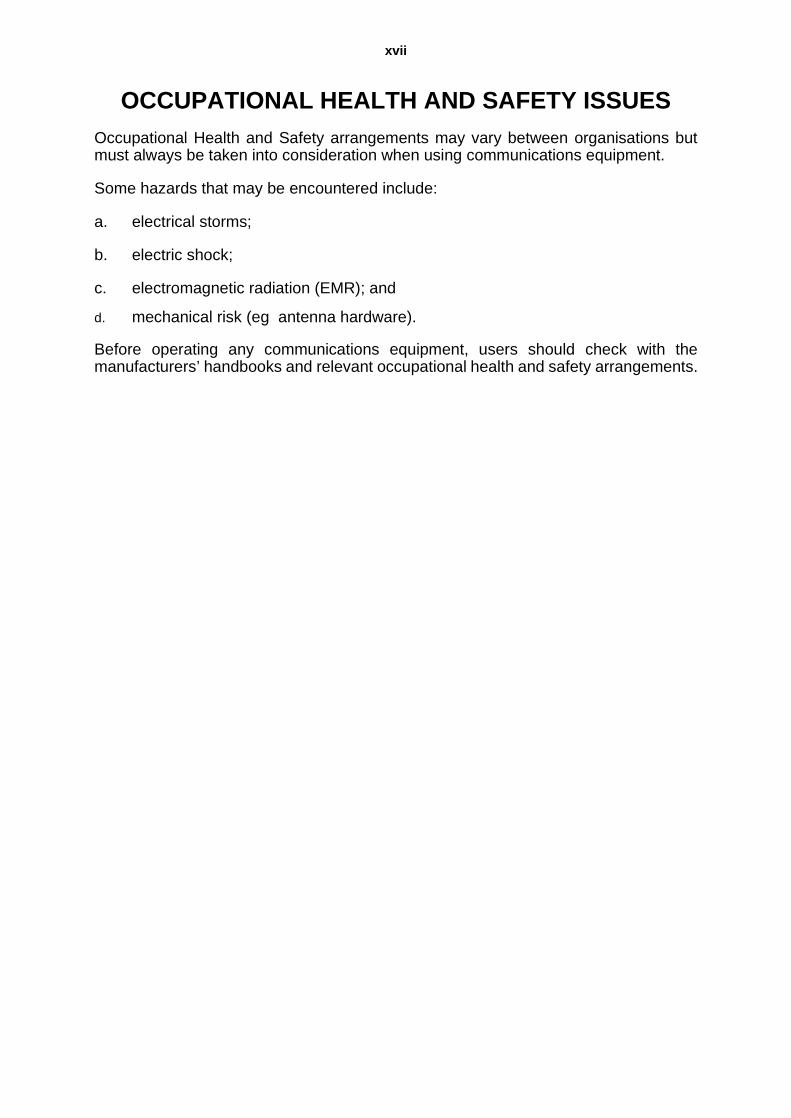
OCCUPATIONAL HEALTH AND SAFETY ISSUESOccupational Health and Safety arrangements may vary between organisations butmust always be taken into consideration when using communications equipment.
Some hazards that may be encountered include:
a. electrical storms;
b. electric shock;
c. electromagnetic radiation (EMR); and
d. mechanical risk (eg antenna hardware).
Before operating any communications equipment, users should check with themanufacturers’ handbooks and relevant occupational health and safety arrangements.


xix
INTRODUCTION
THE COMPREHENSIVE APPROACH TO EMERGENCY/DISASTER COMMUNICATIONS MANAGEMENT
Disasters cause economic and community chaos. Lives are lost, injuries sustained,families disrupted and jobs are often lost. The inevitable interruption to industry andcommerce usually has significant economic consequences at local, regional andnational levels.
Communications are vital in responding to disasters and continuing efforts arenecessary to ensure that equipment and service providers are responsive to the needsof the public safety agencies. On a number of occasions, failure of electroniccommunications has been a major problem in disaster response. Not only shouldequipment be serviceable and reliable, but effective management of communicationresources and information is essential during emergencies and disasters.
Communication networks will be required between organisations and agencies toensure proper coordination of preparedness measures and response operations.
There is also a requirement for community information, which covers prevention,preparedness, response and recovery (PPRR). People must be aware of hazards theyface and how to avoid them, or reduce their effects. They need to be aware ofemergency/disaster management arrangements in their local area and when a threatemerges they must be warned of it and advised what to do before and post-impact.
Typical communication measures under the elements of PPRR include the following:
Prevention/Mitigation:
e. Correct siting of communication assets, ie telephone exchanges, mobile phonefacilities, broadcast stations and major computing networks.
f. On-going access to the legislative planning process, eg Radio CommunicationsAct, Telecommunications Act and any emergency management legislation.
g. On-going access to communications regulator, the Australian CommunicationsAuthority (ACA), for the allocation of national channel blocks and special licensingconditions.
h. Efforts to include communication carriers and service providers in the disastermanagement education process. This will assist them to ‘harden’ their systemsso that they are less vulnerable in times of disaster.
i. Access to the public information planning process.
j. State level plans will need to deal with the assessment of the risk to publicPlanning arrangements for the restoration of these facilities is an important factor.
Preparedness:
a. Emergency/disaster communication plans should be strategic in nature and focuson the larger issues.
b All plans should be regularly exercised and reviewed.

xx
c. Training must support the communication plans.
d. Detailed inventories should be kept on all key communication assets and theirlocations eg transportable mobile telephone cell, and satellite communicationsequipment, portable repeaters etc.
e. The communications aspect of community awareness, information and warningsystems should be implemented.
Response:
a. Communication plans should be implemented as required.
b. Communications coordination should occur across organisations at the highestlevel, at the same time allowing each organisation to operate in an autonomousfashion, with sufficient communication assets to perform their core business.c.Communications resources should be mobilised.
Recovery:
a. Essential community communications should be restored, recognising that evenif the normal communication facilities of a community are unaffected by thedisaster, they will almost certainly be insufficient to support the recovery of thatcommunity.
b. Communication resources should be provided to relief agencies.
c. Communications should be provided for community awareness.
d. Physical restoration of communications infrastructure should be undertaken, ietelephone network, broadcast, radio, television and computer networks.

AUSTRALIAN EMERGENCY MANUALCOMMUNICATIONS
SECTION 1
1COMMUNICATIONS SYSTEMS AND METHODS
All emergency service personnel need to have some knowledge of communicationsmethods and systems. Without this knowledge emergency/counter-disaster operationsmay be adversely affected.
Section 1 contains an introductory overview of the significant communications methodsand lists their advantages and disadvantages, together with a basic description ofoperation.
Section 1 should be understood before referencing other sections of this Manual.

SECTION 1—COMMUNICATIONS SYSTEMS AND METHODS
CHAPTER 1
TELECOMMUNICATIONS NETWORKS CHAPTER 1
INTRODUCTION 1.1
1.1 NATIONAL NETWORK
Australia’s national telecommunications network comprises the PublicSwitched Telephone Network (PSTN), sophisticated data networks, cellulartelephone systems and satellite communications. These networks comprisevast local and trunk systems of complex electronic switching systemsconnected by wire, optical fibre, digital and analogue radio and coaxial cablesystems. Australia's national telecommunications system is regulated by theAustralian Communications Authority (ACA) and serviced, supported andmaintained by various network service providers.
1.2 SPECIAL EMERGENCY AND DISASTER SERVICES
Carriers and service providers, eg Telstra, Optus, may arrange specialisedservices to disaster-affected areas at relatively short notice. These servicesextend beyond the normal range of telecommunication facilities and can bearranged through an emergency/disaster liaison officer. This officer should beidentified in every disaster plan.
1.3 TELECOMMUNICATION NETWORK FEATURES
The majority of Australian premises are serviced by the telephone network andmost people are familiar with its operation. Network security is enhanced bydiversity of switching centres and trunk carrier terminals, alternative routingand site-hardening against natural and other hazards. However, the network isdesigned to handle normal traffic loads and disruption to the network can stilloccur due to traffic congestion or physical interruption, especially indisaster-affected areas.
TELEPHONE SYSTEMS 1.4
1.4 TELEPHONE EQUIPMENT
There are many types of telephone equipment in use throughout Australia,from basic function handsets to the sophisticated multi-function display keystations. All telephones connected to the telephone network must have an ACA(previously Austel) permit number.
1.5 FIXED WIRE TELEPHONE NETWORK
The majority of telephones in Australia are connected to fixed wire telephonesystems; these have a number of advantages and disadvantages:
Advantages DisadvantagesAlready in place In a fixed locationVersatile Calls can be disruptedPublic access Priority to larger usersReliable Vulnerable to physical damage

1.6 CELLULAR (MOBILE) TELEPHONE SYSTEMS
The cellular telephone comprises calling areas divided into cells each of whichis serviced by a low powered transmitter. The cells are interconnected and asa mobile user moves from one cell to another, responsibility for call control ispassed to the cell being entered. Coverage is limited to major cities, towns andother populated areas where a reasonable demand for the service exists. Thecellular system provides full access to the PSTN and is growing at a rapid rate,both in terms of telephones in use and the area coverage.
1.7 There are two mobile telephone systems in general use in Australia, analogueand digital, with three types of telephones available. They are:
a. personal portable (handheld) – low power with a low gain antenna;
b. transportable carry pack – medium power with a low gain antenna; and
c. vehicle mounted – medium power with a high gain antenna.
Note: Cellular telephones are subject to congestion in the same way as thenormal telephone network.
1.8 Advantages and disadvantages of mobile phones are as follows:
Note: Cellular telephones should not be relied upon as the primaryoperational method of communications unless all other avenues have beenexhausted.
1.9 FIELD TELEPHONE SYSTEMS
Military-type field telephones or domestic intercom systems can be effectivealternatives for point-to-point communications in disaster operations. They canrelieve congestion for short distance transmissions, are easy to install and arenot connected to the PSTN. However, field telephone equipment can bedifficult to obtain and the cable interconnecting the units is easily damaged.Domestic intercom systems are readily available from retailers.
High traffic density Can reach saturation and congestionTwo way conversations Not always availableUser friendly Point-to-point onlyPrivacy
Advantages DisadvantagesHigh mobility Congestion can occurInternational roaming with GSM Limited by battery capacityAdaptable to fax and data Coverage is limited in some areasPersonal communications Wide variations in equipmentLow equipment cost No broadcast capability
Advantages Disadvantages

FACSIMILE 1.10
1.10 DESCRIPTION
Facsimile (FAX) machines provide a capability to transmit and receive writtenmessages, printed text, maps or drawings over telephone lines. Capabilitiesvary from machines which are simple to operate to advanced machinesproviding one-touch and coded speed dialing lists and timed transmissions.
1.11 SYSTEM
Most facsimile machines operate over the PSTN; others may operate on digitalmobile telephones, radios and satellite systems. Fax communications can besubject to disruption especially in disaster affected areas. Under normalcircumstances faxes are sent one at a time, or sequentially if there are multipleaddressees. However, Faxstream provides for multiple simultaneoustransmission from the one source document. In addition, facsimiles can be sentto and from computers which have internal fax boards fitted or fax/modemsconnected to a communications port.
1.12 COPY LIFE
Faxes printed on thermal paper rolls are subject to deterioration. If long termretention is required, the reproduced fax should be photo copied. Most modernfax machines print on plain A4, which has the advantage of a single source ofpaper supply for both photocopier and facsimile. Proof of the transmission maybe provided to both the originator and the receiver.
1.13 ADVANTAGES AND DISADVANTAGES
PAGERS 1.14
1.14 Pagers are inexpensive, portable and personal communication devices. Theyprovide one way communication from a central dispatch point to the pagerconcerned and can be used to contact individuals or groups. Users should beaware that delays might occur in the message being delivered. The message
Advantages DisadvantagesLow cost method of sending and receiving manuscripts, maps and text traffic
Thermal paper (if used) has a short life and will fade
Easy to operate Time taken to transfer multiple pagesMultiple address transmission possible
Congestion - may require two or more machines and lines
Plain paper available Information management requirement
Widely used at home and office Cannot receive while sendingCan be used over line, satellite, computers, or radio
Unless automatic, manual resending is required if destination busy
Receipt available to confirm successor otherwise of transmissionHighly reliableMessage received without operator interventionOperates on any telephone line

transmitted may consist of voice, numbers and letters (alphanumeric) or atone, which requires a predetermined response. Tone, voice or alphanumericpagers do not necessarily verify the receipt of the message.
Figure 1:1—Alpha Numeric Personal Pager
1.15 ADVANTAGES AND DISADVANTAGES
SATELLITE COMMUNICATIONS 1.16
1.16 LONG RANGE COMMUNICATIONS
Communication satellites offer the capability to communicate over longdistances with high quality. Unlike High Frequency (HF) radio, these circuitsare not subject to fading or disruption from ionospheric effects. However, somefrequencies used for satellite communication are subject to disruption duringheavy rain.
Advantages DisadvantagesLow cost of one way communications One way messagingOften the range exceeds that of cellular phones
Response not guaranteed
Multiple users can receive the same information - Group Paging
Hardware variations
Message can be stored in the pager until required
Supplier diversity
Low power requirements Limited coverage/rangeWidely used No confirmation of message
receivedHigh reliability Battery life
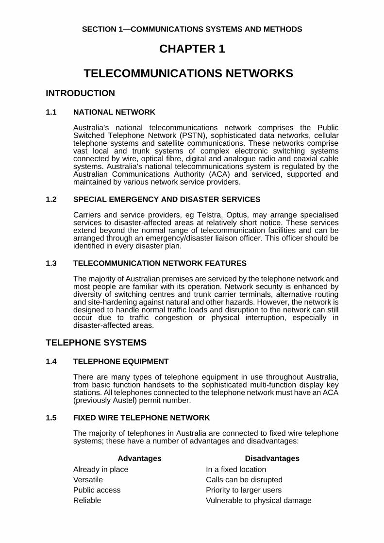
1.17 CONCEPT
The basic concept of satellite communication systems is that an earth stationtransmits a signal to the satellite, which retransmits the signal to other groundstations.
Figure 1:2—Satellite/Earth Station
1.18 TELEPHONE CONNECTION
Most satellite systems provide connections to the telephone system via earthstations in Australia or internationally which permit users to make telephonecalls, transmit data or send facsimile messages. Satellite communicationsystems are affected by network congestion unless special managementarrangements have been made with service providers.
1.19 SIZE
Advances in technology have resulted in a reduction in size and complexity offield earth stations, from large trailer mounted assemblies to suit case size andnow to notebook size. With the introduction of low earth orbiting satellites,hand-held units are becoming available.

Figure 1:3—Portable Earth Station
1.20 ADVANTAGES AND DISADVANTAGES
PERSONAL COMPUTERS AND DATA TRANSMISSION 1.21
1.21 The use of computers for day-to-day tasks is generally well accepted. Thecombination of computing power and high speed data communicationsprovides the connectivity to share information and resources in local and widearea networks.
1.22 NETWORKS
A local area network (LAN) provides a system for intercommunication betweenpersonal computers, workstations, printers and related equipment operatingwithin the same general area. The network is controlled by a file or applicationserver which controls user access to corporate information, data, printers and
Advantages DisadvantagesSmall size of mobile & portable earth terminals
Clear line of sight to satellite required
Equipment cost reducing Limited (if any) broadcast capabilityDiversity of satellites & land earth stations
Slow transmission speed of fax and data
Satphone to Satphone communications available
Relatively high call charges when compared to cellular phone charges
Competitive field for equipment & call charges
EM Radiation hazard to personnel in front of the antenna while equipment is transmitting
Secure communications between earth stations
User friendly
Help desk facilities availableCapable of a carrying voice, fax & data via the PSTNMessage storage system capabilityMobile or fixed installationsRange of power supply optionsNot affected greatly by weather

gateways. For example, staff records, incident details, requests and offers,contact details and Standard Operating Procedures (SOPs) can be stored inelectronic form and accessed quickly by authorised users. Wide area networks(WAN) interconnect remote sites to main systems and local area networks toone another via gateways.
Figure 1:4—Personal Computer (PC)
1.23 PC ADVANTAGES AND DISADVANTAGES
Advantages DisadvantagesAbility to store information electronically
Hardware limitations
Remote access via PTSN possible User reluctance to changeRelatively high speed transmission of information
Incompatibility of some systems
Possible increased user productivity Extensive hardware/variationsWhen linked, users have access to shared information
For high speed data transmission, costly wide band paths are required
One machine can perform many tasks
Rate of change & maintenance of knowledge
Access to a world wide communications system (Internet)
Systems rapidly become obsolete

1.24 COMPUTER-AIDED DISPATCH
By using radio networks, Computer-Aided Dispatch (CAD) systems cantransmit data to Mobile Data Terminals (MDT) in vehicles. This allowsinformation such as job allocation, current status, map information or details onchemical hazards to be interchanged promptly and accurately at a fast rate.
1.25 In addition, MDTs and hand-held units allow the user in the field to accesscentral databases for information on license details, patient records, carregistrations and the like. Police, fire, ambulance, taxi and courier companiesuse these systems to increase the efficient use of the radio spectrum.
1.26 DATA COMMUNICATIONS
The development of data communications evolved from the nature of computersystems. Local and wide area networks enable users on multiple sites to gainaccess to several computers in the same network by using modems, bridgesand routers.
1.27 A wide variety of transmission media is available to the network designer andmany networks employ several of them. Twisted pair cable, coaxial cable, fibreoptics, microwave and satellite channels have information-carrying capacitywhich varies from a few characters per second to millions of characters persecond. The terms bit rate, baud rate and bandwidth are used to describe amedium’s carrying capacity and these measures are interrelated.
1.28 Although computer data is represented in digital form, large amounts aretransmitted in analogue form as transmission facilities were designed foranalogue voice transmission. However, digital networks like IntegratedServices Digital Network (ISDN), voice, data and images are transmitteddigitally. Digital networks have lower error rates, higher transmission rates,better security and do not require digital to analogue conversion and back todigital.
1.29 ELECTRONIC MAIL
Electronic mail, referred to as E-mail, is the ability to transfer messageselectronically. A data communications system serves as the delivery mediumwith E-mail software providing the network mail delivery function. There arepublic and private mail systems; a private system is controlled by a companyand is available only to users within that company. A public mail system isprovided by an electronic mail provider, for a fee, usually an Internet ServiceProvider (ISP), where mail can be routed to unique personal addressesanywhere in the world which have access to the Internet and a serviceprovider. Thus, a manager travelling from one office to another can access mailregardless of their location.
1.30 Distribution of mail is rapid; messages are usually available to recipients withinminutes. Multiple addresses have access to the same message at the sametime. Documents, images and computer programs can be attached and sentwith the message. However, download of attachments requires a high speedmodem and a fast local telephone line as large files take a considerable timeto download; one hour is typical for a 4Mb file.
1.31 INTERNET
The Internet is made up of millions of computers linked in many ways so theycan exchange messages, files, video, sound and programs. It is oftendescribed as a network of networks, but this is only one aspect of the Internet.

When a user is actually logged on to the ‘net’, boundaries disappear. A singlecommand can take the user across several countries and the user may notknow where in the world the computer they are connected to is located.
1.32 The technical complexity of the Internet is hidden. The system is made up ofmillions of links which provide access to other addresses on the ‘net’. Theselinks are provided by telephone lines, ISDN phone lines, trunk lines, microwavelinks and satellite links. A user has to make a connection to the Internet via amodem, phone line, personal computer, software to drive the modem andsoftware with which to ‘browse’ the net.
1.33 WORLD WIDE WEB
The World Wide Web (or the Web or WWW) is the most organised and easiestpart of the Internet to use. The software application, called a browser, used toaccess the Web has a Windows type interface and is easy to use. The Webserver, on which the home page is resident, provides the raw data: text,images, video and audio. The user’s software takes the data and uses theformatting commands embedded in the text files to present it on the user’sscreen. Browsers available are Netscape Communicator/Navigator andMicrosoft Internet Explorer.


SECTION 1—COMMUNICATIONS SYSTEMS AND METHODS
CHAPTER 2
OTHER COMMUNICATIONS METHODS CHAPTER 2
2.1 COURIER SYSTEMS
2.2 Courier systems are used for the hand delivery of information by persons usingaircraft, vehicles or boats. They are flexible and bulky items can be moved, butthey are costly, time consuming and personnel intensive.
2.3 VISUAL/AUDIBLE SIGNALS
2.4 Visual and/or audible systems are basic methods of passing information toothers, or to attract attention. They may include hand signals, lights, sirens,whistles or voice. Such systems are inexpensive and require littleinfrastructure. However, they have limited coverage and are affected byweather.
2.5 PUBLIC MEDIA
2.6 The public media is used extensively for dissemination of information to thepublic in times of disaster through radio, television and newspapers. The mediais easily accessible and reaches a large audience by voice and visual means.However, the audience can not be selected and reception can not beguaranteed. Content is difficult to control and is one-way.


SECTION 1—COMMUNICATIONS SYSTEMS AND METHODS
CHAPTER 3
RADIO COMMUNICATION NETWORKS AND SYSTEMS CHAPTER 3
RADIO NETWORKS 3.1
3.1 FEATURES
Extensive radio communication networks and systems operated bygovernment and private agencies are in use throughout Australia. Thenetworks comprise long-range medium or short-range networks using fixed,mobile and portable equipment.
3.2 Technological advances have resulted in the integration of radios andcomputers to ease the problems of network congestion and inefficientspectrum use. These advances include the development of trunked radiowhich can have both operational and cost advantages.
3.3 FREQUENCY BANDS
Emergency service agencies operate equipment on different frequency bandsincluding:
a. High Frequency (HF);
b. Very High Frequency (VHF);
c. Ultra High Frequency (UHF); and
d. Super High Frequency (SHF).
3.4 Radio communication equipment is usually referred to as two-way radio orradio transceiver. To allow a communication between any two radiotransceivers, both radios MUST operate on the same channel in the samefrequency band.
3.5 ADVANTAGES AND DISADVANTAGES
RADIO TRANSCEIVERS—GENERAL 3.6
3.6 There are a number of different types of radio transceivers. Some of the morecommon types of equipment used by emergency services are described in thefollowing paragraphs.
Advantages DisadvantagesFlexible One transmission at a timeCommunication to vehicles, people, aircraft and boats
Requires trained operators
No physical connection Low traffic capacityNetworking is possible Subject to interferenceBroadcast is possible No security without special measures
May be limited by terrain and or atmosphere

3.7 BASE STATION
A base station is an essential part of any radio communication system and isusually installed in a fixed location. The function of the base station function iscentral control for the dispatch and receipt of messages or information to fieldpersonnel.
Figure 3:1—Local Control Base Station
3.8 REPEATER BASE STATION
An alternative type of base station is known as a talk-through repeater basestation. They can be fixed or portable and function by receiving a signal andretransmitting it automatically.
3.9 By locating this type of station on an elevated site, mobile to mobilecommunications can often be extended to distances in excess of 100 km.Further information is contained in Section 2 of this manual.
MOBILE RADIO TRANSCEIVERS 3.10
3.10 TRANSCEIVERS
Mobile radio transceivers are designed to be fitted to vehicles with powerpermanently connected to the vehicle battery. Where some vehicles presentmounting difficulties, a remote control unit is placed within easy reach of theoperator, allowing the transceiver to be installed in a more convenient location(eg boot mounting).

Figure 3:2—Mobile Radio Remote Control Unit
3.11 ANTENNAS
A variety of antenna configurations and installations can be used and aredetermined by considering:
a. performance requirements;
b. mechanical convenience; and
c. aesthetic appeal.
3.12 HF multi-frequency transceivers are used with antennas that requireadjustment according to the frequency in use. Some of these antennas areautomatically tuned. Other types require manual selection according to thefrequency.
3.13 INTERFERENCE
Care is required to ensure that vehicle electronic/electrical systems and radiotransceivers do not interfere with each other. Ancillary equipment must not beconnected to the permanent power lead of a mobile radio transceiver, as it maycause current overload of the power lead and interference to the transceiver.
HAND-HELD PORTABLE RADIO TRANSCEIVER 3.14
3.14 PORTABILITY
Hand-held portable transceivers are designed to be conveniently carried by aperson and may be attached to waist belts or shoulder straps for ease ofcarrying.
3.15 SIZE
Portable transceivers are physically small and have output powers up to5 watts. Small battery packs are fitted to them which results in lower range andendurance than that achieved with mobile transceivers. Battery packs normallyemploy ‘Nicad' cells, which are rechargeable; dry cell packs may also beavailable.

Figure 3:3—VHF/UHF Hand-Held Portable Transceiver
3.16 PERFORMANCE ENHANCEMENT
The performance of hand-held transceivers is enhanced when they are usedwith repeater base stations.
MANPACK PORTABLE RADIO TRANSCEIVERS 3.17
3.17 FEATURES
Manpack portable transceivers consist of a backpack containing a mobiletransceiver attached to a battery case. The entire set is larger and heavier thana hand-held portable and offers improved range and endurance. A manpackportable radio transceiver usually comprises:
a. HF/VHF/UHF Mobile radio transceiver;
b. battery and charging circuitry;
c. external loud speaker;
d. microphone, connector and bracket;
e. antenna and or antenna connection;
f. battery charger (240 volt AC);
g. battery charger lead (12 volt DC); and
h. canvas carry bag.

3.18 USES
Repackaging of some of the above items enclosed within or attached to ametal case offers versatility and can be used as a:
a. base station with external elevated antenna connected and powered bythe internal batteries on permanent charge;
b. portable mobile with external vehicle antenna powered from its owninternal batteries or the vehicle battery; or
c. portable radio operating with its own antenna and internal batteries.
3.19 BATTERY RECHARGE
A manpack portable radio can usually be operated for about 8 hours beforewithout recharging of the batteries.
Figure 3:4—Manpack Portable Radio Transceiver


SECTION 1—COMMUNICATIONS SYSTEMS AND METHODS
CHAPTER 4
COMMUNICATION EQUIPMENT OPERATION AND PROCEDURES CHAPTER 4
TELEPHONE PROCEDURES 4.1
4.1 ANSWERING
Answer the telephone promptly. When answering a call, identify yourself andyour station or position. Do not say ‘HELLO’, as it is meaningless and wastestime.
4.2 CALLING
When making a call, identify yourself, your station and state the purpose ofyour call. Clear speech and precise diction are essential.
4.3 BACKGROUND NOISE
When using a telephone in a noisy environment, a hand cupped over themouthpiece will reduce extraneous noise being transmitted and may alsoassist the user to hear conversations with less noise.
RADIO COMMUNICATION PROCEDURES 4.4
4.4 BASIC RADIO OPERATING PROCEDURES
Basic radio operating procedures are used for the following reasons:
a. The Radio Communications Act requires a radio service to be controlledby competent operators.
b. Radio communications may suffer from interference, which can result inmisunderstood messages.
c. Communication is only possible in one direction at a time. If two or morepersons transmit at the same time on the same frequency, neithermessage will be received.
d. In emergency or poor operating conditions, radio traffic becomescongested and accuracy can suffer.
4.5 BENEFITS OF STANDARD PROCEDURES
The use of standard procedures ensures:
a. brevity;
b. accuracy;
c. speed; and
d. simplicity.

4.6 USER FACTORS
The following ‘user factors’ (which form the acronym RSVP) will assist inachieving successful transmission of messages:
a. Rhythm—Ordinary conversation has a natural rhythm, which needs to bepreserved when speaking on radio. Say messages in short completephrases that make sense not word by word. Avoid using redundancieslike ‘you know’ or ‘er’.
b. Speed—Speak slightly slower than in normal conversation, avoidingrushing or slurring words. Pause between phrases to give the receivertime to write down the message if necessary.
c. Volume—peak slightly louder than normal conversation. Avoid shouting.
d. Pitch—Use a normal or slightly higher pitched voice.
4.7 PROWORDS
Prowords are pronounceable words or phrases, which have an assignedmeaning for the purpose of expediting message transmissions. Examples ofcommon prowords and their meanings are as follows:
a. ‘Roger’ —Message received and understood.
b. ‘This is’ —Used in conjunction with an identifying radio call sign.
c. ‘Over’ —My transmission is ended and I expect a reply (Never used inconjunction with OUT).
d. ‘Out’ —My transmission is ended, I do not expect a reply (Never used inconjunction with OVER).
e. ‘Say again’—Repeat all of your transmission again (Or identified portionof the message).
f. ‘Wait’ —I must pause during my transmission.
4.8 RADIO CALL SIGNS
Call signs are used to identify stations on a network. The AustralianCommunications Authority (ACA) issues a network call sign (or call signs).However, in some cases, individual organisations may allocate place namesand numbers, used alone or in conjunction with the ACA call signs. Someexamples are as follows:
a. ACA call sign VKX777
b. Individual call sign Curtin Mobile 2
c. Abbreviated call sign Curtin 2
The use of call signs on every transmission is unnecessary and wastes time.However, where there is a risk of confusion, full call signs should be used.
RADIO EQUIPMENT OPERATION 4.9
4.9 CONTROL FUNCTIONS
The majority of radio transceivers manufactured for the Australian market havea number of switches, controls or indicator lights that perform the followingfunctions:

a. Power on-off control—This switches the radio on or off.
b. Volume control—This controls the level of sound from the speaker andshould be set for a comfortable listening level.
c. Mute/squelch control—This eliminates background noise; its setting iscritical for the correct operation of the receiver. Refer to individualequipment instructions.
d. Channel/frequency control—This selects the channel/frequency. Thecorrect channel/frequency MUST be selected or communications contactWILL fail.
e. Indicator lights—These indicate various functions such as power on,signal receive, transmitter on, and channel number. Variations may occurbetween manufacturers.
f. Microphone—This comprises two major components:
(1) A ‘Push to Talk’ switch (PTT) which is used to transmit a message.
(2) A microphone to convert voice to electrical impulses.
Figure 4:1—Mobile Two Way Radio Transceiver
4.10 RECEIVING MESSAGES
To receive a message:
a. Turn the ON/OFF switch to the ON position. (This switch may includeother functions, ie volume or Mute/Squelch).
b. Set the volume control to the mid position.
c. Set the mute control, if fitted, until a rushing noise is heard.
d. Reset the volume to a comfortable listening level.
e. Reset the mute control, if fitted, until the rushing noise is just silenced. Donot advance this control further as weak signals will not be heard.
f. Select the correct channel using the channel switch control:

• On receiving a call, reply with your radio call sign (eg ‘Curtin 2 thisis Curtin Base’).
• After the message is complete, respond to the call, (eg ‘Roger,OUT’).
4.11 SENDING MESSAGES
To send a message:
a. Complete the steps listed in the sub-paras above, ‘Receiving Messages’.
b. Remove the microphone from holder.
c. Listen before transmitting.
d. When the channel is clear, raise the microphone to a position where thethumb touches the face.
e. Depress the Push to Talk (PTT) button on the microphone:
• Give the callsign of the station being called (eg Curtin Base);
• Identify yourself (eg this is Curtin 2);
• Speak briefly and transmit the message (eg I am returning now,OVER).
f. release the PTT button and, if no further transmissions are required,return the microphone to its holder.
Figure 4:2—Making a Call

4.12 TRANSMIT TIMERS
Many transmitters are fitted with a transmit timer to prevent transmissions formore than a preset period, usually one minute. Timers ensure that transmittersare not locked on continuous transmit by a jammed microphone button. Furtherinformation may be obtained from the network manager. Good operatingprocedures will ensure that transmissions are brief and do not exceed thepreset time-out period.
4.13 TRANSMISSION PRINCIPLES
Radio communications are multi-user facilities and require adherence to anumber of basic principles when transmitting as follows:
a. Listen before transmitting.
b. Keep messages short and concise.
c. Urgent or priority messages must be transmitted expediently, withoutdramatisation.
d. Unusual person or place names may be spelt by using the phoneticalphabet.
e. Long messages should be broken into natural sentences.
f. If messages are required to be written by the receiving operator, themessage should be transmitted at writing speed.
g. Avoid the use of jargon terms.
h. Do not use profane language on radio networks, they are not permittedby law.
4.14 PHONETIC ALPHABET
The phonetic alphabet can be used to transmit difficult-to-pronounce words orplace names.
4.15 The excessive use of the phonetic alphabet wastes time on radio networks.Clarification of words can very often be made using plain English spellingwithout the need to resort to phonetic spelling.
A Alpha N NovemberB Bravo O OscarC Charlie P PapaD Delta Q QuebecE Echo R RomeoF Foxtrot S SierraG Golf T TangoH Hotel U UniformI India V VictorJ Juliet W WhiskyK Kilo X XrayL Lima Y YankeeM Mike Z Zulu

4.16 DIFFICULT CONDITIONS/WORDS
In poor conditions, difficult words or groups within the text of plain languagemessages may be spelt using the phonetic alphabet and preceded by theproword ‘I SPELL’. If the operator can pronounce the word to be spelt, they willdo so before and after the spelling to identify the word.
Catenary.....I SPELL….Charlie Alpha Tango Echo November Alpha RomeoYankee......catenary.
4.17 PRONUNCIATION OF FIGURES
When figures are transmitted by radio, they should be pronounced as follows:
Figures or numbers should be transmitted digit by digit, except that exactmultiples of hundreds and thousands may be spoken as such. To distinguishnumerals from words the proword ‘FIGURES’ is to be used preceding thosenumerals.
Examples of spoken numbers:
4.18 PUNCTUATION
Punctuation is to be spoken as shown:
Figure Spoken As0 Zero1 Wun2 Too3 thuh ree4 for wer5 fi yiv6 Six7 se ven8 Ate9 Niner10 wun zerodecimal point day see mal
Number Spoken As44 for wer for wer500 fi yiv hundred7000 se ven thow zand123.4 wun too thuh ree day see mal for wer
Punctuation Spoken As, comma. full stop- hyphen() open brackets, close brackets/ slant or slash‘ ‘ quote, unquote

4.19 MIXED GROUPS
In transmitting a mixed group of letters and figures the prowords ‘Figures’ and‘I spell’ are used as follows:
31—AB7 ‘Figures thuh ree wun hyphen, I spell, alpha bravo figure seven’
4.20 GRID REFERENCES
Grid references are sent digit by digit, preceded by the proword GRID. Theprowords ‘I SPELL’ and ‘FIGURES’ are not required. A grid reference is easierto interpret if a pause is made between the eastings and northings.
Example GRID 97182 is sent as ‘GRID 971 82’
4.21 RADIO CHECKS AND SIGNAL REPORTS
RADIO CHECKS ARE ESSENTIAL BEFORE DEPARTING A DEPOT ORBASE AND WHEN FIRST USING A RADIO AFTER DEPLOYMENT IN THEFIELD. THESE CHECKS ARE PARTICULARLY IMPORTANT BECAUSETHEY ENABLE FAULTY EQUIPMENT TO BE DETECTED AND REPLACEDBEFORE OPERATIONS ARE COMMENCED.
4.22 When testing a radio or establishing a link or network it may be necessary toexchange signal strength reports with the other station/s. Signal strengthreports are as follows:
a. Loud and clear (100% readability).
b. Readable (good readability 90–100%).
c. Weak readable (fair readability 50–90%).
d. Unreadable (readability of less than 10%).
e. Nothing heard (no signal heard, check for faults).
4.23 SENSITIVE MESSAGE TRAFFIC
On occasions emergency services may find it necessary to transmit sensitiveinformation such as casualty lists and incident details. Because radio systemscan be monitored, care should be taken to ensure that sensitive information istransmitted in a coded form. While electronic coding systems can be fitted toradio transceivers, a system of prearranged code words should beprearranged. Consideration should be given to passing sensitive informationby other means, eg telephone (if mobile, GSM only) or personal contact.
4.24 EXERCISE TRAFFIC
During an exercise, transmissions should be periodically prefixed with ‘This anexercise. In the event of a real emergency situation developing, thetransmission should be prefixed with ‘This is not an exercise’.
RADIO NETWORKS 4.25
4.25 RADIO LINK
A radio link is two stations communicating with each other on the sameoperating frequency.

Figure 4:3—Radio Link
4.26 RADIO NETWORK
A radio network is a group of radio stations communicating with each other onthe same frequency.
Figure 4:4—Radio Network
4.27 CONTROL STATION
A Control Station is an assigned station responsible for network managementwhich may include:
a. direction of radio controlled vehicles or personnel;
b. message handling; and
c. network discipline.
RADIO OPERATING CONDITIONS 4.28
4.28 FADING
Due to terrain or interference, radio signals may fade or become unreadable.Fading is most noticeable when communicating with vehicles or portableradios. However, steps can be taken to improve radio communications whensignals are deteriorating; these are:
a. request vehicles or persons to stop or relocate;
b. conduct radio checks until satisfactory communications arere-established, (relocation of one metre is sometimes sufficient).

4.29 INTERFERENCE TO RADIO SIGNALS
Interference is any effect that impairs the reception of a radio signal and canbe natural, manufactured or a combination of both. Natural interference is mostnoticeable on some high frequency (HF) radio networks although very highfrequency (VHF) and ultra high frequency (UHF) radio systems may also beaffected. Natural interference is usually weather related and difficult to predict.Some sources of natural interference are:
a. electrical storms;
b. dust storms;
c. rain;
d. temperature inversions; and
e. ionospheric disturbances.
4.30 MANUFACTURED INTERFERENCE
Manufactured interference is usually caused by electrically operatedmachinery and appliances and may sound like buzzing, humming orhigh-pitched squealing. This type of interference may be continuous orintermittent depending on whether the electrical devices are permanentlyoperated or switched. Examples of manufactured interference are:
a. high-tension powerlines;
b. electricity supply systems and facilities;
c. industrial machinery;
d. computers;
e. fluorescent lighting;
f. neon lighting;
g. electrically operated transport systems;
h. vehicle control systems; and
i. mobile telephones and other radio communication systems.
4.31 Operators of mobile or portable radio communications equipment experiencingmanufactured interference should select alternative locations, free frominterference. Avoid using radios while under trees, in buildings, within industrialareas or under powerlines.
SUMMARY 4.32
4.32 The function of good radio operators is to send and receive messagesefficiently. While they should take pride in achieving a high level ofcompetence, they should not use exotic procedures or jargon which couldconfuse other users on the network.


AUSTRALIAN EMERGENCY MANUALCOMMUNICATIONS
SECTION 2
2ESTABLISHMENT, MAINTENANCE AND OPERATION OF COMMUNICATION SYSTEMS AND EQUIPMENT
Section 2 provides sufficient information for emergency services personnel toestablish, maintain and operate communication systems and equipment.
A full understanding of the information contained in Section 1 is necessary beforereading this section.


SECTION 2—ESTABLISHMENT, MAINTENANCE AND OPERATION OF COMMUNICATION SYSTEMS AND EQUIPMENT
CHAPTER 5
PUBLIC SWITCHED TELEPHONE NETWORK CHAPTER 5
INTRODUCTION 5.1
5.1 The Public Switched Telephone Network (PSTN) is designed for averageday-to-day traffic loads and functions efficiently under these conditions.However, at peak times such as during a disaster, the network can becomecongested. Although most emergency service personnel are aware of thenormal telecommunications facilities, a number of specialised services areavailable which may not be known. Descriptions of some of these services andtheir capabilities are detailed below.
EMERGENCY SERVICES LIAISON PERSONNEL 5.2
5.2 TRAINED PERSONNEL
Telecommunication Carriers and Service Providers may make speciallytrained personnel available at state and regional centres to liaise withemergency service organisations. Due to their extensive knowledge ofsystems and procedures, these officers should be included in all levels ofdisaster management.
5.3 SPECIALISED FACILITIES
Emergency service liaison personnel can provide specialised communicationsfacilities that may be required in times of emergency. Some of these facilitiesmay include portable telephone exchanges, satellite communication servicesand disaster plan (DISPLAN) telephone lines.
TELEPHONE EXCHANGES 5.4
5.4 GENERAL
A telephone exchange is an extensive line switching system that permits theinterconnection of a subscribers telephones within Australia or overseas.Exchanges are usually located within communities and are connected to otherexchanges by various trunk circuits including lines, microwave bearers, opticalfibres or satellite earth stations.
5.5 PRIVATE AUTOMATIC BRANCH EXCHANGE
The private automatic branch exchange (PABX) switches multiple external andinternal telephone connections to specific locations, usually from within thesubscriber’s building. Modern PABX equipment offers a range of additionalfeatures such as call hold, call diversion, in-dialing, speed dialing and grouppick-up. These and other features are controlled by computer software whichcan be re-programmed by trained support staff.
5.6 ALTERNATIVE FACILITIES
An alternative to the PABX may be made available from modern exchanges.These are capable of providing PABX-like facilities to individual subscribers.

Figure 5:1—PABX
TELEPHONES
5.7 GENERAL
Telephones use tone or pulse systems characterised by the dialing speed, withtone dialing being the faster of the two. A telephone that uses tone dialing isnot usually directly interchangeable at the wall socket with a pulse telephoneand vice versa. Care should be taken before interchanging telephones toensure they are set to the correct dialing system. However, in someinstallations, specific wall-socket configurations inhibit connection of incorrecttelephone appliances. All telephones must have an ACA (Austel) permit beforeconnection to the PSTN.
5.8 SPECIAL TELEPHONE FEATURES
Modern telephone systems can now provide features previously only providedby a PABX, eg call waiting or call diversion.

5.9 GROUP ALERT CALLING
Systems are available (such as Telstra’s ERS7) that allow individualsubscriber’s telephones to be linked to a common call group so that calls forassistance from the public will cause all telephones to ring simultaneously aswell as activating external audible alarms if required.
5.10 FAXSTREAM
Faxstream is a digital network provided by Telstra to enhance the operationalcapability of standard facsimile (fax) machines. The digital system improvesthe speed of transmission, enhances the clarity of the printed copy and allowsa simultaneous broadcast facility to other facsimile users. The normal faxmachine is only able to communicate with one other fax machine at any onetime.
5.11 Faxstream works by having the subscriber’s fax communicate with aFaxstream computer. The computer has access to multiple lines and thus cansend a message to many locations simultaneously, ie broadcast.
5.12 When all the faxstream messages are delivered, the originator is provided witha delivery receipt from the system computer. Because these receipts aretreated as low priority, delays may be experienced in their return. Therefore, ifurgency is a concern direct dial fax should be used. Machines on theFaxstream network can communicate with non-faxstream machines.Communication Managers may consider including their own fax machinenumber (or ideally, a receive-only fax machine) at the end of the faxstreamgroup and thereby receive an indication that the messages have beendelivered. (Faxsteam is a propriety name and other carriers or serviceproviders may provide a similar service).
5.13 CELLULAR TELEPHONES
There are two cellular telephone systems available in Australia. The originalsystem, known as Advanced Mobile Phone System (AMPS), is an analoguenetwork and is due for phased withdrawal, in selected areas, in Year 2000.Global System Mobile (GSM) is a digital system which uses the spectrum moreefficiently and offers particular advantages over the AMPS system, includingbetter privacy and priority access.
5.14 Some difficulty may occur with data or fax transmissions with the AMPSsystem, while the GSM will generally provide a more reliable transmissionpath. Telephones on either system communicate with the other through thePSTN.
5.15 The risk of congestion is increased when cellular telephones are used,especially in major emergency or disaster situations and therefore they shouldonly be used in a support role.


SECTION 2—ESTABLISHMENT, MAINTENANCE AND OPERATION OF COMMUNICATION SYSTEMS AND EQUIPMENT
CHAPTER 6
OTHER SYSTEMS AND SERVICES CHAPTER 6
MARITIME RADIO SERVICE 6.1
6.1 Telstra operate the Maritime Radio Service, a system of HF and VHF coastalradio stations which continually monitor specific frequencies. The Serviceprovides manual or automatic (direct dialing) connection to the PSTN. Somecoastal stations can be accessed by land mobile or portable stations.
ROYAL FLYING DOCTOR SERVICE 6.2
6.2 Royal Flying Doctor Service (RFDS) radio networks are primarily designed toprovide access to medical help in remote areas. Other services may includeeducation, telegram, telephone, and general radio communications. The radioservice operates in the HF spectrum and emergency response is available24 hours a day.
WIRELESS INSTITUTE CIVIL EMERGENCY NETWORK 6.3
6.3 The Wireless Institute Civil Emergency Network (WICEN) is a division of theWireless Institute of Australia, the governing body for amateur radio operators.WICEN was formed to provide specialised radio communications for thecommunity in times of disaster. Due to the extensive range of frequencies,equipment, and expertise available to them they may be usefully included inemergency or disaster plans.
CITIZENS BAND RADIO SERVICE 6.4
6.4 Citizens Band Radio (CB) is an inexpensive form of radio communicationavailable for personal use. There are two frequency bands available for thisservice, HF (27MHz) and UHF. An extensive UHF repeater system is availableacross Australia.
6.5 OPERATOR DISCIPLINE
All CB radio systems are subject to disruption by poor operator discipline andshould not be relied upon entirely for emergency operations. Both frequencybands have 40 channels available, which include designated emergencycalling channels.
SATELLITE COMMUNICATIONS 6.6
6.6 An increasing number of civilian communication satellites are in use around theworld. They perform a range of tasks including:
a. two way voice transmission;
b. two way data transmission; and
c. public broadcasting.
The two way functions are those that are of special interest to emergencyservices personnel.
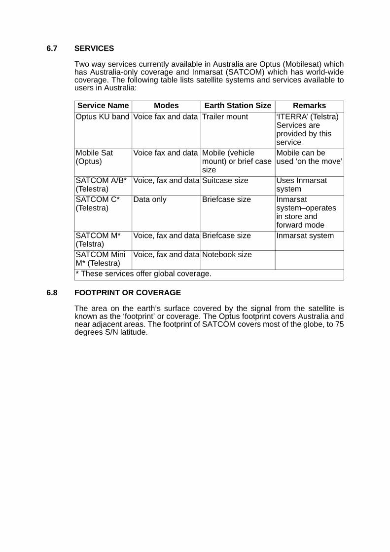
6.7 SERVICES
Two way services currently available in Australia are Optus (Mobilesat) whichhas Australia-only coverage and Inmarsat (SATCOM) which has world-widecoverage. The following table lists satellite systems and services available tousers in Australia:
6.8 FOOTPRINT OR COVERAGE
The area on the earth’s surface covered by the signal from the satellite isknown as the ‘footprint’ or coverage. The Optus footprint covers Australia andnear adjacent areas. The footprint of SATCOM covers most of the globe, to 75degrees S/N latitude.
Service Name Modes Earth Station Size RemarksOptus KU band Voice fax and data Trailer mount ‘ITERRA’ (Telstra)
Services are provided by this service
Mobile Sat (Optus)
Voice fax and data Mobile (vehicle mount) or brief case size
Mobile can be used ‘on the move’
SATCOM A/B* (Telestra)
Voice, fax and data Suitcase size Uses Inmarsat system
SATCOM C* (Telestra)
Data only Briefcase size Inmarsat system–operates in store and forward mode
SATCOM M* (Telstra)
Voice, fax and data Briefcase size Inmarsat system
SATCOM Mini M* (Telestra)
Voice, fax and data Notebook size
* These services offer global coverage.

Figure 6:1—SATCOM Satellite Footprint/Coverage
6.9 ORBITS
When a satellite is placed in a critical orbit that maintains its position above aspecific point on the earth’s surface, it is said to be in a ‘geo-synchronous’ or‘geo-stationary’ orbit. Geo-synchronous satellites orbit the earth at the samespeed as the earth and are located approximately 36000 kilometres above theequator. These satellites cause a delay of 0.3 of a second in receiving speech.
6.10 Other satellites vary their position in relation to the ground and may only bevisible at certain times. These satellites are able to deal with messages on astore and forward basis and are therefore more appropriate for data messages.Several orbiting satellites can be arranged in constellations so that messagescan be transferred between satellites either direct or via earth stations. Storeand forward operation is not necessary and therefore the constellations canhandle voice, fax and data traffic in real time.

6.11 LOW EARTH ORBIT SATELLITES
Low Earth Orbit Satellites (LEOS) operate at lower altitudes and requirereduced power levels for operation. They are designed to operate withhand-held telephones. Networks employing LEOS require in excess of fiftysatellites for global coverage.
6.12 MEDIUM EARTH ORBIT SATELLITES
Increasing the altitude of the satellite orbit requires fewer satellites (in the orderof twelve) to provide global coverage. Only a small increase in hand-held earthstation power may be necessary. Such systems employ Medium Earth OrbitSatellites (MEOS).
6.13 FUTURE DIRECTIONS
Access to hand-held telephone satellite communications with global accesswill become available. A number of companies are developing systems whichemploy LEO and MEO satellites. The first system, Iridium, is due to be inoperation in 1999.
Figure 6:2—Future Satellite Directions
6.14 Some planned networks propose to employ hand-held digital telephones thatwill access a conventional terrestrial mobile telephone cell if available or asatellite if a terrestrial cell cannot be accessed, ie they will be dual modesystems.
6.15 NAVIGATION SATELLITE SYSTEMS
The Global Positioning System (GPS) is a space-based navigation satellitesystem which provides highly accurate signals to ground-based, air and marinereceivers which calculate and display positions in latitude and longitude with anaccuracy of 100 metres. Although these systems are not communicationsatellite networks, information from them can be impressed on communicationsatellite systems to provide position information for such tasks as AutomaticVehicle Location (AVL).
6.16 Hand-held and mobile GPS receivers are available for navigation. Addedfeatures of these units permit the operator to undertake a wide array ofnavigation tasks.

SECTION 2—ESTABLISHMENT, MAINTENANCE AND OPERATION OF COMMUNICATION SYSTEMS AND EQUIPMENT
CHAPTER 7
RADIO COMMUNICATIONS FUNDAMENTALS CHAPTER 7
INTRODUCTION 7.1
7.1 A knowledge of the fundamental principles of radio communications willprovide a greater understanding of communications and could enhanceeffective communications.
RADIO WAVES 7.2
7.2 DESCRIPTION
The action of a radio wave cannot be seen but can be likened to ripples causedby a stone being dropped into a pond. The resulting inner wave is high inintensity and then diminishes with distance. The wave action will continue ifstones are dropped at regular intervals into the pond. Radio waves behave ina similar way except they usually travel through space rather than water. Radiowaves travel at the speed of light in free space (300,000,000 metres persecond).
7.3 A RADIO WAVE
A radio wave or one cycle of radio energy can be shown diagrammatically asin Figure 7:1.
Figure 7:1—Frequency of One Hertz
7.4 WAVE LENGTH
The length of one single wave (or one complete cycle) is also the distancetravelled during the transmission of one cycle.
7.5 FREQUENCY
The number of complete waves (or cycles) passing a point in one second istermed ‘frequency’:

Figure 7:2—Frequency of Two Hertz
a. One wave per second is a frequency of one HERTZ (Hz).
b. 1000 waves per second/ Hz is 1 KILOHERTZ (kHz).
c. 1,000,000 waves per second/Hz is 1 MEGAHERTZ (MHz).
d. 1,000,000,000 waves per second/Hz is 1 GIGAHERTZ (GHz).
RADIO FREQUENCY SPECTRUM 7.6
7.6 The characteristics of radio signals vary according to frequency and aredivided into nominal ‘bands’ which represent significant changes inperformance. The bands are listed below:
7.7 OVERLAPPING OF BANDS
The characteristics of radio signals do not change sharply at band edges butgradually alter, eg a 27 MHz signal exhibits characteristics of both HF andVHF.
Bands Frequency Range
Uses
Medium Frequency (MF)
300 kHz–3 MHz AM Broadcast services.
High Frequency (HF)
3 MHz–30 MHz Short wave broadcast, Royal Flying Doctor, marine services.
Very High Frequency (VHF)
30 MHz–300 MHz
FM and television boradcasting, two way radio services, aviation.
Ultra High Frequency (UHF)
300 Mhz–3000 Two way radio services, television broadcasting, UHF CB, aviation, microwave links.
Super High Frequency (SHF)
3000 MHz–30 GHz
Radar, satellite, telemetry, microwave links.

SECTION 2—ESTABLISHMENT, MAINTENANCE AND OPERATION OF COMMUNICATION SYSTEMS AND EQUIPMENT
CHAPTER 8
RADIO TRANSMISSION PRINCIPLES, SYSTEMS AND EQUIPMENT CHAPTER 8
INTRODUCTION 8.1
8.1 This chapter describes radio propagation principles, communication systems,radio transceivers and ancillary equipment in common use with emergencyservice organisations.
VERY HIGH FREQUENCY (VHF) AND ULTRA HIGH FREQUENCY (UHF) PROPAGATION 8.2
8.2 LIMITATIONS
VHF and UHF systems are line of sight operations; if two stations are in visualcontact, communications are probable. However, if distance becomes toogreat, signal strength decreases so that transmissions become too weak to bereceived. Smoke, bush fires and some types of pollution may also reducecommunication distances.
8.3 Although line of sight is not achieved, communication from behind objects suchas buildings and hills is still possible. Other effects such as reflections anddiffraction cause the radio signals to bounce off reflective surfaces or to curveover the top of hills and may allow effective communication to be maintained.
8.4 DEAD SPOTS
Reflected signals sometimes combine in such a way to severely reduce signalstrengths, resulting in ‘dead spots’. These dead spots are often highlylocalised. Shifting the position of one of the transceivers by as little as a metre,may provide acceptable communication.
8.5 RANGE
The nominal range of a VHF or UHF system under ideal operating conditionsvaries between 50–100 km depending on a number of variables, includingantenna height.
8.6 EMERGENCY SERVICES USE
Emergency Service Organisations predominantly use equipment in VHF andUHF bands operating in the SIMPLEX (one to one mode over a radio line ofsight path), or REPEATER mode. For a detailed explanation of REPEATERoperation see the paragraph titled Repeater Base Stations below.

Figure 8:1—VHF/UHF Line of Sight Path
8.7 SUPER HIGH FREQUENCY (SHF) PROPAGATION
SHF radio signals operate over line of sight paths. Point-to-pointcommunication services such as microwave links and earth stations forsatellite links are the major users of this band.
VHF/UHF BASE STATIONS 8.8
8.8 LOCAL CONTROL
To ensure optimum range and provide best line of sight conditions, VHF andUHF base stations need to be located on elevated sites. Where such a site isnot available, the antenna system must be installed on a high mast. If the basestation and the control unit are jointly located, the configuration is known as aLOCAL CONTROL base station, as shown in the figure below:
Figure 8:2—VHF/UHF Base Station Local Control

8.9 REMOTE CONTROL
Where an extended service area is required and it is not practical to collocatethe radio base and its control, the two elements are separated, with the basestation being installed at an elevated site and remotely controlled via leasedlandlines, private landlines or a radio link.
Figure 8:3—VHF/UHF Base Station Remote Control
8.10 SIMPLEX OPERATION
When operating a VHF/UHF mobile or portable radio to a base station, thecommunication path will be between the base station and the mobile/portableradio. Other mobile radios operating on the network may not be heard by allusers unless they are in the immediate vicinity. In this situation, transmissionsand reception on the same frequency are known as ‘simplex operation’. Twofrequency simplex is also available.
8.11 REPEATER BASE STATIONS
There is virtually no difference in the radio coverage area between a basestation or a talk-through repeater base station located at the same site.However, if a manually controlled base station is not practical, and directmobile to mobile communications is to be maintained then a talk-throughrepeater base station must be employed.
8.12 A talk-through repeater base station functions by receiving a signal andsimultaneously retransmitting it automatically without intervention of a basestation operator. Separate transmit and receive frequencies are necessary toachieve talk-through repeater base station. When communicating to anotheroperator via a repeater, the user is accessing the repeater not the radio at theend of the communication path.

Figure 8:4—Repeater Base Station
8.13 PORTABLE RADIO BASE STATION
Base stations including repeaters can operate in a portable configuration. Theyare normally operated with a portable antenna and mast and are usuallypowered by portable generator and battery back-up. Such repeaters aretemporarily deployed in areas that require enhanced communication facilities.Care must be taken to ensure that these base stations are not located in areasthat may cause interference to other radio communication services.Accordingly, portable radio base station equipment should be installed byqualified personnel only.
8.14 SCANNING
Most modern radio transceivers are able to automatically switch betweenchannels in sequence when the scan option (if fitted) is selected, ie scan aselection of frequencies. The receiver will pause when encountering an activechannel. There are a variety of methods of scanning but the basic concept isthat the operator can monitor multiple channels with a single transceiver.
8.15 DISADVANTAGE OF SCANNING
A significant disadvantage of scanning is that while the receiver is locked tosignals on one channel, messages on other channels may be missed. For thisreason, a single radio should not be used in scanning mode during anoperation. Where two or more transceivers are used, scanning should be usedon one radio only.
8.16 TELEPHONE/RADIO INTERFACE
Telephone/radio interface devices permit radio systems to access the PSTN sothat personnel in the field can communicate with others on the normaltelephone system from their mobile or portable radio. However, unless theradio system is secure, conversations may be heard by other radio users.

8.17 TRUNKED RADIO SYSTEMS
As the radio spectrum is of finite size and subject to increasing demands byusers, alternative systems are being developed to provide optimum use of thespectrum. One of these systems is ‘trunked’ radio.
8.18 Unlike conventional radio, where a group of users are assigned a channel (orchannels) permanently, a trunked radio system dynamically allocates achannel to a user as the need arises. Computer technology controls theoperation of the radio system and results in reduced delays and more efficientuse of the available spectrum. Before the advent of trunked radio, channelsoften became busy, resulting in excessive waiting time, interruptions and‘transmitted over’ communications.
8.19 Trunked radios provide several channels, or frequencies, for use by users.When a conversation is completed, the channel is made available to otherusers. Idle channels are available to the system for allocation on demand.
8.20 Several different protocols are used in trunked radio systems; these areidentified by abbreviations and codes, changed as the design is upgraded.Three systems which have been developed are:
8.21 Trunked radio systems provide the ability to send and receive voice and dataefficiently while providing quick access, wide area coverage and a high degreeof confidentiality. Access to the public telephone system is available. However,direct access between trunked systems is not possible, nor can a single radioconnect to more than one system.
8.22 The protocols allow several enhancements such as Automatic VehicleLocation (AVL), duress alarm and Global Positioning System (GPS) positioncorrection signals. Most importantly, trunked radio systems usually offer moreextensive coverage than private mobile radio networks through a network ofstrategically located base stations. Networks can be either public, shared orprivate trunked. A typical trunking system consists of a central control unit andportable (hand-held) or vehicle mounted mobile units. Units can be mixed andmatched in any way to suit requirements.
TETRA (Trans European Trunked Radio)APCO 25 (Association of Public Safety
Communications Officials)MPT 1327


SECTION 2—ESTABLISHMENT, MAINTENANCE AND OPERATION OF COMMUNICATION SYSTEMS AND EQUIPMENT
CHAPTER 9
HIGH FREQUENCY RADIO OPERATION CHAPTER 9
9.1 COMPLEXITIES AND VARIABLES
The operation of High Frequency (HF) radio is complex and a number ofvariable factors can assist or restrict communications. Considerable trainingand experience is necessary for effective use of HF radio. While VHF and UHFsystems are usually employed for line of sight communications, HF remains aneffective medium for communication over short, medium and long distances.Distances in excess of 3000 kilometres are within the capabilities of HF radio.
9.2 HIGH FREQUENCY PROPAGATION
HF propagation has two distinct features, ground wave and sky wave.
Figure 9:1—HF Propagation
9.3 GROUND WAVE
Some of the energy radiated from the transmitter follows the ground contoursand is termed ground wave. Ground wave transmissions are usually shortrange because a significant amount of energy is absorbed by the terrain duringtransmission. Pure ground wave transmissions are not subject to fading.
9.4 SKY WAVE
The situation with sky wave transmissions is totally different. Radio frequency(RF) energy from the transmitter is radiated into the ionosphere whichcomprises layers of gas surrounding the earth. Gases within these layers areionised (electrically charged) by radiation from the sun and become conductivecausing refraction (or bending) of the signals back towards earth. This allowstransmission over considerable distances.

9.5 SKIP ZONE
Often there is a gap in the coverage of the transmitter between ground waveand sky wave. This is termed the skip zone or distance where the signal istoo weak to be of any useful purpose. The problems associated with the skipzone may be overcome by relay techniques via a third station that has skywave communication with both ends of the link. Additional procedures that mayassist include changing frequency or changing the type of antenna in use.
9.6 SELECTING THE CORRECT FREQUENCY
The ionospheric layers also bend signals at varying degrees depending on thefrequency in use. Operating frequencies must be chosen according to the timeof the day and the distance of the communication path required. Generally,lower frequencies are more suitable for use at night while higher frequenciesare used during the day. The height and density of the ionosphere changeswith time of day, season and solar activity, causing fading on HFtransmissions. Solar storms can completely disrupt HF transmissions.
Figure 9:2—Selecting the Correct Frequency
9.7 IONOSPHERIC PREDICTION SERVICE (IPS)
The (radio and space) IPS is a Commonwealth Government agency thatstudies the characteristics of HF transmission and issues predictions on theperformance of HF sky wave communications over designated distances andfrequencies according to the date and time of day. This service is available onrequest and may be obtained by telephone.
9.8 IPS produces a three monthly calculator that indicates the optimum frequencyto be used over a given distance at a given time of the day. The agencyprovides a number of other services including training, warnings of unusualsolar activity and a recorded telephone information service that is amendeddaily. IPS also produce a computer software package (called ASAPS), whichis designed to produce predictions for particular paths, date and times.

Figure 9:3—Frequency Prediction Calculator
HF BASE STATIONS
9.9 LOCAL CONTROL
Fixed HF radio base stations may be controlled locally or remotely. Locallycontrolled bases have their transmitter and receiver combined (transceiver)and connected to an external antenna. The transceiver is usually a mobileradio connected to a mains operated 12 volt DC power supply.
Figure 9:4—HF Base Local Control
9.10 REMOTE CONTROL
Due to local electrical noise problems, or difficulty in finding sufficient space forantennas, HF transceivers may be remotely located, but controlled from acentral point via leased landlines, private landlines or a radio link.
9.11 When multiple HF services are collocated, it may be necessary to separatetransmitters and receivers. This is achieved by installing all transmitters at onesite and all receivers at a separate site.

Figure 9:5—HF Base Remote Control with Separate Transmitter and Receiver Sites
9.12 STATION SITING
For optimum performance, the following should be considered when siting HFbase stations:
a. They should be located away from sources of electrical noise such aspower lines, industry, computers, portable generators.
b. Sufficient space should be allowed for the erection of antennas withappropriate orientation.
c. They should be installed in areas with good soil conductivity (moistground).

HF MOBILE RADIO COMMUNICATIONS 9.13
9.13 TRANSCEIVERS
Several problems may be encountered when using HF mobile transceivers toprovide communication from vehicles operating in the field as follows:
a. Proximity to powerlines and other external sources of electricalinterference. The problem may be overcome by moving.
b. Vehicle electrical components including:
(1) spark plugs;
(2) alternators;
(3) oil and fuel sensors;
(4) windscreen wiper motors; and
(5) engine management computers.
These problems can be largely eliminated by vehicle electricalsuppression techniques.
c. Proximity to other vehicles. This problem may be overcome byre-locating.
d. Proximity to industrial areas and machines. This problem may beovercome by re-locating to an electrically quieter area; and
e. Atmospheric conditions, such as thunderstorms or high humidity. Thisproblem may be overcome by changing frequency.
9.14 WHIP ANTENNAS
The purpose of the antenna is to transmit and receive a signal efficiently andis a critical part of the HF transceiver in a vehicle. There are two types of HFmobile antennas in common use:
a. Auto tune antenna. These antennas are tuned automatically according tothe frequency selected and is accomplished by the operator from withinthe vehicle.
b. The ‘Wander Lead’ is a critical piece of the antenna in that each whip hasa unique length of lead in millimetres which is stamped on the antennaand is measured from plug tip to plug tip. Replacement by longer orshorter leads will degrade the performance of the antenna.

Figure 9:6—Tapped Whip Antenna
9.15 PRECAUTIONS
As performance of the equipment will be degraded, operators should ensureno person approaches closer than one metre from the antenna when a HFmobile transceiver is being used. Holding the antenna during transmission maycause skin burns.

Figure 9:7—Typical HF Mobile Installation
HF PORTABLE RADIO COMMUNICATIONS
9.16 TRANSCEIVERS
HF portable radio transceivers are generally low powered units and consist ofa mobile transceiver attached to a rechargeable battery pack, enclosed in acarry case. The antenna can be either a shortened tapped whip, similar to themobile version, or an external wire antenna.
9.17 If fitted with a tapped whip antenna, the transceiver should be placed on asheet of metal, space blanket or similar material when it is being operated fromthe ground. An alternative is to place the transceiver on the bonnet of a vehicleto provide the necessary ground plane (artificial earth).
9.18 An adequate earth is essential for antenna efficiency and can be achieved bya one to two metre earth stake driven into the ground with a wire connected tothe radio housing. To ensure a good earth, tip a bucket of salty or bore wateraround the stake. Alternative sources of liquid should be considered if no wateris available.
9.19 When used with an external wire antenna, the performance of the radio isenhanced. An internal antenna tuning unit enables the wire antenna to betuned to the frequency selected on the radio.
OPERATING HF RADIOS
9.20 BASIC OPERATING STEPS
a. Switch off the mute control if fitted and adjust volume to desired level.

b. Select the correct operating frequency according to the time of day andcommunication distance as per IPS or other technical instructions.
c. Check that the right antenna is connected.
d. Tune the antenna or select the proper tapping for the frequency required;some antennas are broadband or automatically tuned and do not requireadjustment.
e. Make the call.
f. If no contact is made or the results are poor, arrange with the otheroperator to try alternative channels until best communications areachieved.
9.21 MODERN HF SELECTIVE CALLING (SELCALL) SYSTEMS
Selcall is a facility available on modern HF radios which enables noise freeoperation and allows specific individual radios or groups of radios to be called.Its operation is similar in concept to the use of a telephone, in that the callingradio ‘dials' the called radio or group of radios, transmits the code and onlythose fitted with the Selcall code will respond. All other Selcall fitted radios willremain silent.
9.22 Each HF radio or group of HF radios may have a unique electronic codednumber allocated, known as a Selcall number. The number is transmittedwhenever the Selcall button on the radio is depressed.
9.23 There are a number of coding standards in use in Australia. Care must betaken to ensure that the appropriate standard is used in the radio or selectivecalling will not take place. The design of the modern Selcall code is based ona number of digits, eg 0001–9999. For further information refer to the operatorsmanual or organisation SOPs. When Selcall and non-Selcall radios are usedtogether, care must be taken to ensure interoperability by disabling the Selcallmute control. However, conventional muting can still be used. A particularadvantage of Selcall operation is that it enhances scanning.
9.24 Other important features of Selcall (but not necessarily available on allsystems) are as follows:
a. Automatic reply (revertive) once contact is made. This gives the callingoperator an audible indication that positive contact has been made withthe called radio. However this is not a guarantee that voicecommunications can be achieved.
b. Absent operator indication, eg alpha-numeric display and/or flashing redlight.
c. Only parties directly involved in the radio conversation need listen to it.
9.25 HF BEACONS
Modern HF radio networks employing Selcall allow the user to judge whethervoice communication over a given distance could be successful on selectedfrequencies. On transmitting a Selcall to a base station, a beacon replies if thesignal path is good. If the Beacon does not reply, the signal path is not goodand the operator should try another frequency. Refer to the paragraph on theionospheric predictions at the beginning of this chapter for guidance on correctfrequency selection.

SECTION 2—ESTABLISHMENT, MAINTENANCE AND OPERATION OF COMMUNICATION SYSTEMS AND EQUIPMENT
CHAPTER 10
BASIC RADIO MAINTENANCE CHAPTER 10
RADIO COMMUNICATIONS EQUIPMENT SHOULD BE INSTALLEDAND SERVICED BY QUALIFIED TECHNICAL PERSONNEL
OPERATOR MAINTENANCE 10.1
10.1 Operators should carry out regular maintenance as follows:
a. Visual check of all connections.
b. Regular ‘on air’ testing.
c. Keep batteries charged and ensure that dry cells are removed fromequipment in storage.
d. Keep the radio clean, dry and dust free.
e. Check all accessories.
If a fault is found, the radio should be labelled and the fault described withsufficient information to aid repair and return of the repaired item. Accessoryitems should also be included.
FAULT FINDING PROCEDURE 10.2
10.2 TOTAL FAILURE
Should the radio fail totally (ie no transmit or receive), the following fault findingprocedures should be carried out:
a. Ensure the radio is switched on and indicator lamps are glowing.
b. Ensure power leads to battery or power supply are properly connected tothe appropriate terminals.
c. Check fuses in power leads and power supply unit. If replacement isrequired ensure that the same value fuse is used.
d. Check antenna and microphone connections. If an external loudspeakeris being used, ensure it is plugged in.
e. Ensure the radio is switched to an operational frequency.
f. Check remote head connections, if fitted.
10.3 RECEIVER FAILURE
Proceed as follows:
a. Check volume control setting.
b. Check microphone/loud speaker connections or external speaker.
c. Ensure radio is set to an operational frequency.
d. Check mute control setting (if fitted).
e. Check antenna is connected and erected.

10.4 TRANSMITTER FAILURE (ASSUMING THE RADIO IS RECEIVING)
a. Ensure microphone is connected and the ‘Push to Talk’ button is working.
b. Ensure the transmit lamp is glowing when transmitting.
c. Check power lead connections from power source to radio.
10.5 FAULT FINDING BY SUBSTITUTION
Minor radio faults may be found and cleared by using the substitution method.This involves substituting suspect components with known good componentsin a methodical manner, ie replace a suspect faulty microphone with a knowngood microphone.
RADIO BATTERIES—THEIR CARE AND USE 10.6
10.6 Counter-disaster and many emergency operations are usually conducted inadverse conditions which place heavy reliance upon battery-operatedcommunications equipment. The proper care of batteries is essential if reliablecommunications using portable radio equipment are to be maintained. Threemain types of batteries are in general use: dry cells, gel cells (lead-acid) andnickel cadmium cells.
10.7 DRY CELLS
Dry cells are commonly used in a variety of battery-powered consumerequipment such as torches, transistor radios and children’s toys. The only typeof dry cells that should be used in portable radio equipment are the alkalinetype. Alkaline cells have a useful shelf-life of about 12 months and should bekept in cool storage. Common alkaline cells are not re-chargeable.
10.8 All types of dry cells should be removed from equipment before it is placed instorage to avoid damage by leaking batteries. The manufacturer’s instructionsshould always be followed when replacing batteries as incorrect installationcan damage the equipment.
10.9 GEL CELLS
Gel cells are also known as sealed lead-acid batteries and are used in mostmanpack portable radios. These batteries are rechargeable with relatively slowrecharging times of 8 hours being typical. This type of battery must be chargedwith the specific charger supplied, otherwise severe damage to the equipmentcan occur.
10.10 Gel cell batteries have good endurance and are normally capable of operationfor about 8 hours before recharging is necessary. Most manpack portabletransceivers can be left on charge permanently without causing any damage.It is imperative that radios with flat batteries be placed on charge without delayas gel cells left in a discharged state will suffer severe damage.
10.11 The replacement of gel cells should only be done by qualified technicalpersonnel under workshop conditions. The major disadvantage of gel cells istheir excessive weight.

10.12 NICKEL CADMIUM CELLS
Nickel Cadmium batteries, or ‘NiCads’, are a type of rechargeable battery usedon virtually all hand-held portable radios. NiCads have the advantage that theyare compact, relatively light and can be fast-charged in about one hour with asuitable battery charger. However, there can be variations in thecharacteristics of NiCad batteries of different manufacture.
10.13 To maintain optimum performance these batteries should not be subjected to:a. continual overcharging;
b. complete discharging;
c. reduced-cycle charging; andd. storage in excessively hot or cold locations.
Because the output voltage remains virtually constant until the batteries arealmost discharged, little warning of battery failure is given.
10.14 When a NiCad battery is partially discharged and recharged for a number ofcycles, the batteries charged capacity is severely reduced in direct relation tothe number of charge/discharge cycles. For example, if a 10-hour battery isdischarged for one hour and then recharged for a significant number of cycles,the battery may develop a shortened, full-charge capacity of only one hour.This is called ‘memory effect’ and can be overcome by almost fully dischargingthe battery and recharging it for a number of cycles. This is known asconditioning and automatic chargers/conditioners are available andrecommended to extend the life of NiCad batteries.
10.15 Batteries that give an indication of extreme heat during the charging processare likely to be damaged and become unusable. A timer on the power outlet isrecommended to control the charging process. Stored batteries should becharged/discharged on a regular basis, eg every four to six weeks.
10.16 Environmental and safety considerations should be considered whendisposing of batteries. The supplier/manufacturer’s advice should be sought ondisposal of batteries.
Note: To maintain maximum battery life, the manufacturers instructions oncharging and discharging should be followed.
Figure 10:1—Nickel Cadmium Batteries


SECTION 2—ESTABLISHMENT, MAINTENANCE AND OPERATION OF COMMUNICATION SYSTEMS AND EQUIPMENT
CHAPTER 11
RADIO OPERATING PROCEDURES CHAPTER 11
INTRODUCTION 11.1
11.1 Whilst the standard radio operating procedure detailed in Section 1 wouldnormally be adequate for efficient message transmission over good qualityradio circuits, additional standard procedures are necessary for the efficientexchange of messages over poor quality radio networks.
11.2 PREREQUISITE
A full understanding of the information contained in Section 1 is necessarybefore reading this chapter. Some subjects in this section have been coveredbriefly in Section 1 and are covered again in more detail for the benefit of theadvanced radio operator.
11.3 RADIO NETWORKS
A typical radio network diagram appears below. Note that:
a. VKX777 is the network call sign,
b. only the station call sign is to be shown inside the circle,
c. Curtin Base is the control station, and
d. the network control station is always shown at the bottom of the fan.
Figure 11:1—Radio Network

11.4 NETWORK DISCIPLINE
To function effectively, radio networks need to be operated in a disciplinedmanner. Good network discipline requires that correct operating procedures beused so that control is maintained. Networks that suffer a loss of disciplinedegenerate to the point where they are unable to carry useful message traffic.Where network discipline has failed, the control station must intervene andinstruct all stations to cease transmission until called. The control station thenre-establishes the network ensuring that the previous improper procedures areeliminated.
TRAFFIC 11.5
11.5 Traffic is a general term given to all communications which are handled on anetwork. There are two types of traffic, formal and informal.
11.6 FORMAL TRAFFIC
Formal traffic is written, released by an authorised officer and recorded by thecommunications centre (COMCEN). It includes:
a. registered messages, including Situation Reports and Monitor Reports;
b. facsimile messages; and
c. telex messages.
11.7 INFORMAL TRAFFIC
Informal traffic does not require recording by the COMCEN and is nottraceable; it includes:
a. conversations; and
b. unregistered messages.
CALLING AND ANSWERING 11.8
11.8 INTRODUCTION
The following paragraphs contain examples of calling and answeringprocedures:
a. Prowords Used:
THIS IS
OVER
OUT
WAIT
WAIT OUT
WILCO
ROGER
b. Parts of a Call—A call consists of the following parts:
NET CALL SIGN—Identifies the net.
STATION CALL SIGN—Identifies the station(s) being called

THIS IS—Proword. Preceding calling station’s call sign.
STATION CALL SIGN—Identifies the calling station.
TEXT—The message itself.
ENDING SIGN—‘OVER’—the proword used to indicate that thetransmission has ended, but further transmissions are expected fromother station(s).
Example of a Call:
VKX777 Curtin 1 THIS IS Curtin Base move now OVER.
c. Parts of an Answer—The answer consists of the following parts:
STATION CALL SIGN—Identifies station answering.
TEXT—Answer, or receipt.
ENDING SIGN—OVER—End of my transmission—I expect a reply.
OUT—Proword to indicate that the station expects no further involvementin that call.
WAIT—Proword indicating that the receiving operator must pause duringthe transmission.
WAIT OUT—Proword indicating that the receiving operator must delaytransmission for more than five (5) seconds and will resume later with aninitiating call.
Example of an answer:
Curtin 1 WILCO OUT
d. The above procedures are known as Abbreviated Procedures and areused in good working conditions. Full Procedures are used in difficultworking conditions and are explained later in this Manual.
TYPES OF CALLS 11.9
11.9 SINGLE CALL
A single call occurs between any two stations on the net. All call signs may beomitted after the initial call and reply.
Example:
Curtin Base says: ‘VKX777 Curtin 1 THIS IS Curtin Base have your ropes arrived OVER’
Curtin 1 says: ‘Curtin 1 No when did they leave OVER’
Curtin Base says: ‘FIGURES 20 minutes ago OVER’
Curtin 1 says: ‘ROGER OUT’
11.10 MULTIPLE CALL
a. Multiple calls are used when one station wishes to call two or morestations on the net, but not all stations.
b. Stations are called in alpha-numeric order and they answer in the sameorder. Should a station fail to answer, the next station in sequential ordershall pause 5 seconds and then reply as normal. After the last station hasreplied, the station, which previously failed to answer, may reply.

Example: Base calling four sub-stations of a seven station net.
Curtin Base says: ‘VKX777 Curtin 1 Curtin 2 Curtin 3 Curtin 4 THIS ISCurtin Base, fresh batteries are available at FIGURES 0900 hours OVER’
Curtin 1 says: ‘Curtin 1 ROGER OUT’
Curtin 2 says: ‘Curtin 2 ROGER OUT’
Curtin 3 says: ‘Curtin 3 ROGER OUT’
Curtin 4 says: ‘Curtin 4 ROGER OUT’
Note: As this a Multiple Call, call signs must continue to be used after theinitial call and reply.
11.11 NET CALL OR ALL STATIONS CALL
These types of calls are used to call all stations on the net; stations reply inalpha-numeric order. The same rules apply as with multiple calls.
Example: The net consists of four stations.
Curtin Base says:‘VKX777 all stations THIS IS Curtin Base tarpaulins are nowavailable OVER’.
Curtin 1 says: ‘Curtin 1 ROGER OUT’
Curtin 2 says: ‘Curtin 2 ROGER OUT’
Curtin 3 says: ‘Curtin 3 ROGER OUT’
Curtin 4 says: ‘Curtin 4 ROGER OUT’
Curtin Base says: ‘Curtin BASE ROGER OUT’
11.12 ALL STATIONS EXCEPT CALL
If only the majority of Stations are to be called, Curtin Base may use: AllStations except ............. procedure.
Example:
Curtin Base says: ‘VKX777 ALL STATIONS except Curtin 4 THIS IS CurtinBase Tarpaulins are now available OVER’
Curtin 1, Curtin 2 etc. reply in sequence.
ESTABLISHING A RADIO NET 11.13
11.13 RADIO CHECK AND SIGNAL STRENGTH CALLS
Prowords used are:
RADIO CHECK
NOTHING HEARD
ROGER
LOUD
GOOD
WEAK
VERY WEAK

FADING
CLEAR
READABLE
DISTORTED
INTERFERENCE
UNREADABLE
SIGNAL STRENGTHS
11.14 INITIAL PROCEDURE
The procedure to establish a radio network is to ensure that all stations on thenet are able to communicate with each other on the same frequency. Beforeany station leaves its HQ, the members of that station must know the:
a. primary net frequency;
b. alternative net frequency, if any;
c. organisation of the net;
d. time the net is to open;
e. net call sign;
f. station call signs; and
g. senior sub-station.
Note: At all times, sub-stations should establish communications with the netcontrol station as they leave the base.
11.15 RADIO CHECKS (SIGNAL STRENGTHS AND READABILITY)
a. The net control station establishes the net by ordering sub-stations toreport the strength and readability of its signal by using the prowordRADIO CHECK, which means ‘What is my signal strength andreadability?’ The sub-stations answer the call in turn giving their report ofsignal strength and readability of the control station. The control stationwill complete the call by informing sub-stations of their signal strength andreadability. If the answer is LOUD and CLEAR, the proword ROGER willsuffice.
b. The following prowords are for use when initiating and answering queriesconcerning signal strength and readability:
RADIO CHECK—What is my signal strength and readability, that is, howdo you hear me?
ROGER—The use of the proword ROGER in reply to a radio checkmeans the transmission was satisfactory. This will save air time. ROGERreplaces loud and clear.
SIGNAL STRENGTHS—What is the signal strength and readability of allthe other stations on the net. Each sub station will say how it hears all theother sub-stations.
11.16 REPORT OF SIGNAL STRENGTHS
a. LOUD—Your signal is very strong.
b. GOOD—Your signal is good.

c. WEAK—Your signal is weak.
d. VERY WEAK—Your signal is very weak.
e. FADING—At times your signal fades to such an extent that continuousreception cannot be relied upon.
11.17 REPORT OF READABILITY
a. CLEAR—Excellent quality.
b. READABLE—Quality is satisfactory. This proword may be used with theproword DISTORTED or INTERFERENCE.
c. DISTORTED—Having trouble reading you because your signal isdistorted.
d. INTERFERENCE—Having trouble reading you due to interference.
e. UNREADABLE—The quality of your transmission is so bad that I cannotread you.
11.18 EXAMPLES OF TRANSMISSIONS TO ESTABLISH THE NET
a. When all stations are LOUD and CLEAR (ROGER).
Curtin Base says: ‘VKX777 all stations this is Curtin Base RADIO CHECKOVER’
Curtin 1 says: ‘Curtin 1 ROGER OVER’
Curtin 2 says: ‘Curtin 2 ROGER OVER’
Curtin 3 says: ‘Curtin 3 ROGER OVER’
Curtin 4 says: ‘Curtin 4 ROGER OVER’
Curtin 5 says: ‘Curtin 5 ROGER OVER’
Curtin Base says: ‘Curtin BASE all stations ROGER OUT’
b. When some of the stations are not receiving clearly:
Curtin Base says: ‘VKX777 all stations THIS IS Curtin Base RADIOCHECK OVER’
Curtin 1 says: ‘Curtin 1 ROGER OVER’
Curtin 2 says: ‘Curtin 2 ROGER OVER’
Curtin 3 says: ‘Curtin 3 WEAK BUT READABLE OVER’
Curtin 4 says: ‘Curtin 4 ROGER OVER’
Curtin 5 says: ‘Curtin 5 LOUD WITH INTERFERENCE OVER’
Curtin Base says: ‘Curtin BASE all stations ROGER OUT’
c. When requesting a radio check, the originating station, after the otherstations have replied, will in its reply give a radio check to other stations.
11.19 SIGNAL STRENGTH REPORTS
Signal strength reports may be requested by any station, but normally by thenet control station. The signal strength report will inform each station how theyare being received by all other stations on the net. The signal strength reportis usually preceded by a radio check.
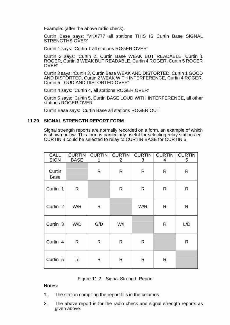
Example: (after the above radio check).
Curtin Base says: ‘VKX777 all stations THIS IS Curtin Base SIGNALSTRENGTHS OVER’
Curtin 1 says: ‘Curtin 1 all stations ROGER OVER’
Curtin 2 says: ‘Curtin 2, Curtin Base WEAK BUT READABLE, Curtin 1ROGER, Curtin 3 WEAK BUT READABLE, Curtin 4 ROGER, Curtin 5 ROGEROVER’
Curtin 3 says: ‘Curtin 3, Curtin Base WEAK AND DISTORTED, Curtin 1 GOODAND DISTORTED, Curtin 2 WEAK WITH INTERFERENCE, Curtin 4 ROGER,Curtin 5 LOUD AND DISTORTED OVER’
Curtin 4 says: ‘Curtin 4, all stations ROGER OVER’
Curtin 5 says: ‘Curtin 5, Curtin BASE LOUD WITH INTERFERENCE, all otherstations ROGER OVER’
Curtin Base says: ‘Curtin Base all stations ROGER OUT’
11.20 SIGNAL STRENGTH REPORT FORM
Signal strength reports are normally recorded on a form, an example of whichis shown below. This form is particularly useful for selecting relay stations eg.CURTIN 4 could be selected to relay to CURTIN BASE for CURTIN 5.
Figure 11:2—Signal Strength Report
Notes:
1. The station compiling the report fills in the columns.
2. The above report is for the radio check and signal strength reports asgiven above.
CALLSIGN
CURTINBASE
CURTIN1
CURTIN2
CURTIN3
CURTIN4
CURTIN5
CurtinBase
R R R R R
Curtin 1 R R R R R
Curtin 2 W/R R W/R R R
Curtin 3 W/D G/D W/I R L/D
Curtin 4 R R R R R
Curtin 5 L/I R R R R

11.21 SCHEDULED CALLS
Radio schedules are established and maintained for the following purposes:
a. To ensure that all stations on a radio network are in communication. Thescheduled call should be initiated from Control and conducted atpredetermined intervals.
b. Transmission of non-urgent messages at intervals during a 24 hourperiod instead of the operator having to maintain a continuous listeningwatch.
TRANSMISSION OF INFORMATION 11.22
11.22 PROWORDS
Prowords used are:
MESSAGE
LONG MESSAGE
SITREP
SEND
MORE TO FOLLOW
ALL AFTER
OUT TO YOU
11.23 UNWRITTEN INFORMATION
Information, which does not have to be written down, may be sent withoutusing a proword in the initial transmission (called an offer) if the sending stationis reasonably sure that the recipient is ready to receive it.
Example:
Curtin Base says: ‘VKX777 Curtin 1 THIS IS Curtin Base. Go to the airport foryour stores, OVER’
Curtin 1 says: ‘Curtin 1, WILCO OUT’
11.24 WRITTEN INFORMATION
Use of the proword ‘MESSAGE’ in the offer indicates that the information mustbe written down. This may apply to information, which contains figures,unusual words, grid references etc. The information must be sent at writingspeed to enable the recipient to write it down. The sending station will achievethis aim by:
a. ghost writing over the information while sending; or
b. pausing between phrases.
Example:
Curtin Base says: ‘VKX777 Curtin 1 THIS IS Curtin Base MESSAGE OVER’
Curtin 1 says: ‘Curtin 1 SEND OVER’
Curtin Base says: ‘Move to Grid 242 691 OVER’
Curtin 1 says: ‘WILCO OUT’

11.25 LONG MESSAGE PROCEDURE
If the information will take more than thirty seconds to send, or is longer than15 words, the following procedure should be used:
a. The information is offered using the proword LONG MESSAGE.
b. The information is to be sent in segments, each lasting 15 words orapproximately thirty seconds. Remember ‘I SPELL’, ‘FIGURES’ andother prowords are included in this rule.
c. Each segment, except for the last segment, is to terminate with theproword ‘MORE TO FOLLOW OVER’.
d. When segmenting a written message prior to offering, the initiating stationmust ensure that the end of each segment does not end with:
phonetics (eg I spell BRAVO);
phonetically-spelt words (eg alloy I SPELL ALPHA LIMA LIMA OSCARYANKEE, alloy); and
figures or punctuation.
e. Receiving stations are to acknowledge each segment with ROGEROVER or, if necessary, ask for repetitions.
f. After obtaining receipts for each segment from all receiving stations thesender must pause for five seconds. This will allow other stations tointerject for any urgent traffic transmissions.
g. The station initiating a long message may interrupt its transmission tosend a more urgent one.
h. If there is no interjection the calling station transmits the last word orphrase contained in the previous segment and proceeds immediatelywith the new segment.
i. When the calling station completes the last segment of the message, theproword OVER is used. Recipients who have successfully received thewhole message then respond with ROGER OUT.
Note: Accuracy and speed are the basic essentials for all communications.
11.26 EXAMPLE OF LONG MESSAGE
Curtin Base has a long message for Curtin 1 and says: ‘VKX777 Curtin 1 THISIS Curtin Base LONG MESSAGE OVER’
Curtin 1 says: ‘Curtin 1 SEND OVER’
Curtin Base says: ‘Blankets located in store at Grid 674 395, Some areunserviceable MORE TO FOLLOW OVER’
Curtin 1 requires no corrections or repetitions and says: ‘ROGER OVER’
Curtin Base observes a 5 second pause to allow any urgent messages to bepassed then continues ‘Unserviceable due to water damage full stop transporthas been arranged for good blankets tomorrow OVER’
Curtin 1 has received the message and ends the transmission by saying.‘ROGER OUT’

CORRECTIONS AND REPETITIONS 11.27
11.27 PROWORDS
Prowords used are:
CORRECTION
SAY AGAIN
ALL AFTER
ALL BEFORE
WORD AFTER
WORD BEFORE
FROM __________
TO _____________
SPEAK SLOWER
UNKNOWN STATION
11.28 CORRECTION DURING TRANSMISSION
The procedure is as follows:
a. When an error is made by a transmitting operator, the proword‘CORRECTION’ is to be transmitted followed by the last word, group,proword or phrase correctly transmitted; the transmission then continues.Care should be taken to avoid using words or prowords which appearmore than once in the message.
Example:
Curtin Base says: ‘VKX777 Curtin 1 THIS IS Curtin Base move to yourlast CORRECTION your first location OVER’
Curtin 1 says: ‘Curtin 1 WILCO OUT’
b. When an error in transmission is made and is not discoveredimmediately, but is discovered before the ending proword ‘OUT’ istransmitted, a correction is to be transmitted as per the example below.When making such a correction, the word, group, proword or phrase,before or after the correction, is to be properly identified.
Example:
Curtin 1 says: ‘VKX777 Curtin 1 THIS IS Curtin Base stores will arrive infigure 6 trucks from Carnarvon CORRECTION WORD BEFORE trucksfigure 7 OVER’
Curtin Base says: ‘Curtin 1 ROGER OUT’
11.29 CORRECTION AFTER A MESSAGE HAS BEEN SENT
Used if it is necessary to make corrections after a receipt has been obtainedfor a message. A further message identifying the original, and the portion to becorrected, must be sent.

Example:
Curtin Base says: ‘VKX777 Curtin 1 THIS IS Curtin Base reference mymessage on trucks CORRECTION ALL AFTER trucks from Carnamah OVER’
Curtin 1 says: ‘Curtin 1 ROGER OUT’
Notes:
1. Curtin 1 must correct the original message and ensure that the correctionis passed to all personnel to which the station is responsible; and
2. when the text of a MESSAGE to a number of stations (multiple and netcalls) is found to be incorrect all stations must be called and thecorrections transmitted.
11.30 REPETITIONS
a. When words are missed or are in doubt, repetitions are to be requestedand given to the affected receiving station before receipting the message.The proword SAY AGAIN can be used alone or in conjunction with others.
b. In complying with requests for repetitions, the initiating (sending) stationis to identify that portion which is being repeated and sent using theproword ‘I SAY AGAIN’. With messages less than ten words, it is quickerto send the whole message than part of it.
Example:
Curtin Base says:‘VKX777 Curtin 1 THIS IS Curtin Base stores will arrivein figures 7 trucks from Carnamah at noon on Monday OVER’
Curtin 1 says: ‘Curtin 1 SAY AGAIN ALL AFTER noon OVER’
Curtin Base says: ‘I SAY AGAIN, WORDS AFTER, noon on Monday,OVER’
Curtin 1 says: ‘ROGER OUT’
11.31 SPEED OF TRANSMISSION
When a receiving station has difficulty in recording a written message becausethe sending operator is speaking too rapidly, the receiving operator mustrequest a reduction in the speed of transmission by the use of the proword‘SPEAK SLOWER’.
11.32 UNKNOWN STATION
When a station hears a call for itself, but has missed the call sign, it may askfor a repetition of the call sign.
Example:
Curtin Base says: ‘VKX777 Curtin 1 THIS IS __________ OVER’
Curtin 1 says: ‘UNKNOWN STATION THIS IS Curtin 1, SAY AGAIN call signOVER’
Curtin Base says: ‘Curtin 1 THIS IS Curtin Base I SAY AGAIN call sign CurtinBase ‘OVER’
Curtin 1 says: ‘ROGER OVER’
Curtin Base will now send the message as normal.

VERIFICATIONS AND CANCELLATIONS 11.33
11.33 PROWORDS
Prowords used are:
VERIFY
I VERIFY
WAIT OUT
DISREGARD
CANCEL
11.34 VERIFICATIONS
When a station receives a message from another station, which it has reasonto doubt or suspect may be incorrect, the receiving station should ask for averification of the message. When a verification has been requested thesending station must take the message to be verified to the originator (author)of the message for that person to authenticate or correct as necessary.
Example:
Curtin Base says: ‘VKX777 Curtin 1 THIS IS Curtin Base reference your storesrequest VERIFY figures 200 stretchers OVER’
Curtin 1 says: ‘Curtin 1 wait OUT’
The operator at Curtin 1 must check with the message originator to establishthat the message is correct.
If Correct:
Curtin 1 says: ‘VKX777 Curtin Base THIS IS Curtin 1 reference the storesrequest I VERIFY figures 200 stretchers OVER’
Curtin Base says: ‘Curtin Base ROGER OUT’
If Incorrect:
Curtin 1 says: ‘VKX777 Curtin Base THIS IS Curtin 1 reference the storesrequest CORRECTION figures 300 stretchers OVER’
Curtin Base says: ‘Curtin Base ROGER OUT’
Note: If the message has been found to be incorrect and the original messagehas been sent to more than one station, all stations must be informed of thecorrection.
11.35 CANCELLING TRANSMISSIONS AND MESSAGES
a. Cancelling During Transmission:
During a transmission, but prior to the ending proword, a transmissionmay be cancelled by the use of the proword ‘DISREGARD THISTRANSMISSION, OUT’
b. Cancelling an Immediate Past Transmission:
Curtin Base says: ‘VKX777 Curtin 1 THIS IS Curtin Base CANCEL mylast transmission OVER’
Curtin 1 says: ‘Curtin 1 ROGER OUT’

c. Cancelling a Previous Transmission:
Curtin Base says: ‘VKX777 Curtin 1 THIS IS Curtin Base CANCEL mystores request OVER’
Curtin 1 says: ‘Curtin 1 ROGER OUT’
MISCELLANEOUS PROCEDURES 11.36
11.36 PROWORDS
Prowords used are:
FETCH (name)
WAIT OUT
SPEAKING
11.37 ARRANGING A PERSON TO PERSON CONVERSATION
a. If there is a requirement for one station to speak to a specific individual(not the operator) at another station, the procedure is arranged by theoperators using the following prowords:
FETCH (name)—Meaning the person indicated is to be called to speakon the radio.
WAIT OUT—Used by the receiving operator to allow time to arrange forthe called person to be present.
SPEAKING—Used by the called person when replying.
Example:
Curtin Base wishes to speak to the Coordinator at Curtin 1.
Curtin Base says: ‘VKX777 Curtin 1 THIS IS Curtin Base FETCHCoordinator OVER’
Curtin 1 says: ‘Curtin 1 WAIT OUT’
Curtin 1 will now bring the coordinator to the radio and brief him on itsoperation.
Curtin 1 says: ‘VKX777 Curtin Base THIS IS Curtin 1 CoordinatorSPEAKING OVER’
Curtin Base says: Curtin Base replies........
b. The person to person call is arranged by the two radio operators. Theymust ensure that the individuals for whom they are arranging the callknow how to operate the radio sets prior to providing them with theservice, ie able to use the Push To Talk Switch etc.
CHANGING FREQUENCY 11.38
11.38 PROWORDS
Prowords used are:
CHANGE TO
CHANGE NOW
WILCO
11.39 PROCEDURE
Where more than one frequency is available on a radio system, occasions mayarise when a change of frequency is desirable. The order to change frequencyis given simply by quoting the channel number on VHF and UHF or by quotingthe frequency in kilohertz on HF and using the prowords CHANGE TO andCHANGE NOW.
Example:
Curtin Base says: ‘VKX777 All stations THIS IS Curtin Base CHANGE TOchannel 4 OVER'
Curtin 1 says: ‘Curtin 1 WILCO OVER’
Curtin 2 says: ‘Curtin 2 WILCO OVER’
Curtin 3 says: ‘Curtin 3 WILCO OVER’
Curtin Base says: ‘All stations THIS IS Curtin Base CHANGE NOW OUT’
If all stations do not respond or cannot comply, the control station must makealternative arrangements for the change and advise the whole net. A radiocheck will now be carried on the new frequency.
CLOSING DOWN 11.40
11.40 PROWORDS
Prowords used are:
CLOSE DOWN
CLOSE DOWN NOW
WILCO
Note: No station should close down, or leave the radio, even only for a fewminutes, without prior permission from the net control station.
11.41 PROCEDURE
The net control station must ensure that no net individual sub-station is closeddown until the net control station is absolutely sure that the net or sub-stationis no longer required. The usual practice for closing down sub-stations is towait until they return to base and individually close them down thus ensuringthe safety of teams in the field. If communications are to be reopened at a latertime, the net control station must ensure that everyone concerned is aware ofthe time communications are to be re-opened, and the frequency to be used,before it closes the stations down.
11.42 When the time to order a close down over the radio arrives, and all stations aresatisfied regarding arrangements for re-opening, the net control station ordersthe net or sub-stations to close down. The net control station may do this byusing the proword ‘CLOSE DOWN’.
Example 1:
Curtin Base says: ‘VKX777 all stations THIS IS Curtin Base CLOSE DOWNOVER’
Curtin 1 says: ‘Curtin 1 WILCO OVER’
Curtin 2 says: ‘Curtin 2 WILCO OVER’
Curtin 3 says: ‘Curtin 3 WILCO OVER’
The control station records each response and, if satisfied that all stations havereplied and there is no further traffic, transmits.
Curtin Base says: ‘VKX777 all stations THIS IS Curtin Base CLOSE DOWNNOW OUT’
Example 2:
The net control station transmits to all stations to close down and givesreopening directions.
Curtin Base says:‘VKX777 all stations THIS IS Curtin Base CLOSE DOWN.The net will reopen at figures 0800 hours tomorrow on this frequency OVER’
Curtin 1 says: ‘Curtin 1 WILCO OVER’
Curtin 2 says: ‘Curtin 2 WILCO OVER’
Curtin 3 says: ‘Curtin 3 WILCO OVER’
Curtin Base says: ‘VKX777 all stations THIS IS Curtin Base CLOSE DOWNNOW OUT’
DIFFICULT WORKING CONDITIONS 11.43
11.43 CAUSES
Difficult working conditions may be caused by:
a. excessive noise;
b. fading;
c. unintentional interference;
d. sharing frequency with other users;
e. shadowing of some sub-stations by hills;
f. weak signals from one or more sub-stations; and
g. congested net.
11.44 PROCEDURES
The following paragraphs detail procedures which should be followed whenworking in difficult conditions.
11.45 WORDS TWICE
a. Prowords used are:
WORDS TWICE
END WORDS TWICE
b. This procedure can also be used when communications begin todeteriorate. WORDS TWICE procedure may be initiated by any station onthe net for any or all transmissions. call signs and offers are alltransmitted twice. Full procedure must be used for transmission usingWORDS TWICE procedure.
c. When working conditions improve the procedure is cancelled by theprowords ‘END WORDS TWICE’.

Example:
Curtin Base says: ‘VKX777 Curtin 1 THIS IS Curtin Base message OVER’
Curtin 1 says: ‘Curtin Base Curtin Base THIS IS THIS IS Curtin 1 Curtin 1 sendsend WORDS TWICE WORDS TWICE OVER OVER’
Curtin Base says: ‘Curtin 1 Curtin 1 THIS IS THIS IS Curtin Base Curtin BaseWORDS TWICE WORDS TWICE move move to to grid grid 736 643 736 643now now OVER OVER’
Curtin 1 says: ‘Curtin Base Curtin Base THIS IS THIS IS Curtin 1 Curtin 1WILCO WILCO OUT OUT’
11.46 RELAY PROCEDURE
a. Prowords used are:
RELAY THROUGH
RELAY TO _______
FROM ______
THROUGH ME
b. If direct radio communications between any two sub-stations fail, trafficmay be relayed through a third station that is in contact with both.
Example:
Curtin 1 calls Curtin 2 but receives no reply: ‘VKX777 Curtin 2 THIS ISCurtin 1 move now OVER’
Curtin 1 calls Curtin 2 again: ‘VKX777 Curtin 2 THIS IS Curtin 1 movenow OVER’
Still no reply so Curtin 1 requests Curtin 3 to relay to Curtin 2: ‘VKX777Curtin 2 THIS IS Curtin 1 nothing heard OUT to you. Curtin 3 THIS ISCurtin 1 RELAY TO Curtin 2 move now OVER’
Curtin 3 has heard the call and will now send it to Curtin 2: ‘Curtin 1 THISIS Curtin 3 ROGER OUT to you. Curtin 2 THIS IS Curtin 3 from Curtin 1move now OVER’
Curtin 2 has received the message: ‘Curtin 2 WILCO OUT’
Note: a station acting as a relay station assumes full responsibility forensuring that the message is passed to the station it was originally intendedfor.
11.47 FREE AND DIRECTED NETS
a. Prowords
Prowords used are:
THIS IS A FREE NET
THIS IS A DIRECTED NET
b. Free Net
Under normal conditions a net is free and traffic between sub-stations onthe net is uninhibited. The control station determines when the situationrequires this freedom to be curtailed.
Example:
Curtin Base says: ‘VKX777 All stations THIS IS Curtin Base THIS IS AFREE NET OVER'
Curtin 1 says: ‘Curtin 1 WILCO OUT’
Curtin 2 says: ‘Curtin 2 WILCO OUT’
Curtin 3 says: ‘Curtin 3 WILCO OUT’
c. Directed Net
When working conditions are difficult or the flow of traffic is heavy andtraffic must be regulated, the control station may order the net to bedirected. In a directed net, the control station intercepts each offer andmust direct the involved sub-stations on when and how to pass the traffic.The control station is therefore able to regulate all traffic on the net. Thisregulation and procedure must apply to, and be acknowledged, by allsub-stations on the net.
Example:
Curtin Base says: ‘VKX777 ALL stations THIS IS Curtin Base, THIS IS ADIRECTED NET OVER’
Curtin 1 says: ‘Curtin 1 WILCO OUT’
Curtin 2 says: ‘Curtin 2 WILCO OUT’
Curtin 3 says: ‘Curtin 3 WILCO OUT’
d. When a net is directed, an offer by one sub-station to another is answeredby the control station in one of the following ways:
Prowords Used:
SEND YOUR MESSAGE OUT
SEND YOUR SITREP OUT
WAIT OUT
THROUGH ME OVER
RELAY THROUGH (sub-station)
Example:
Curtin 2 says: ‘VKX777 Curtin 1 THIS IS Curtin 2 message OVER’
Curtin Base says: ‘Curtin Base SEND YOUR MESSAGE OUT’
Curtin 1 says: ‘Curtin 1 send OVER’
Curtin 2 says: ‘Curtin 2 move to GRID 643 718 OVER’
Curtin 1 says: ‘Curtin 1 WILCO OUT’
Note: On all occasions Curtin Base must give direction to proceed, or notproceed, to the offering Station.
If Curtin Base does not wish the message to proceed it will use the prowordWAIT OUT.

THE TRANSMISSION OF FORMAL MESSAGES 11.48
11.48 OFFERING
Formal messages are always to be offered and written down by the receivingoperator. The offer is to include the following:
a. The proword FORMAL MESSAGE or LONG FORMAL MESSAGE.
b. Any additional information which may aid the receiving operator, such asthe requirement for additional copies when the message has to bedelivered to more than one addressee by the receiving station.
RADIO OPERATOR LOGS 11.49
11.49 All radio operators should maintain a log while they are on duty. The log fulfilsa useful administrative function to:
a. check whether a message has been transmitted or received;
b. determine details of other station signal strengths;
c. log the opening and closing of stations;
d. brief radio operators coming on duty;
e. log details of interference for later action; and
f. log all transmission difficulties.
11.50 INFORMATION
The log should include the following data:
a. the handover of the radio station from one operator or user to another;
b. the time of opening and closing of the station;
c. all procedural transmissions;
d. causes of delays in transmission or reception of a message;
e. frequency adjustments and changes;
f. call signs of other stations that cause interference (so that unsatisfactoryfrequency allocation may be corrected, if possible);
g. unusual occurrences, such as procedural violations;
h. record of informal messages and voice conversations sent to otherstations on the net (recorded as completely as possible); and
i. intrusion and interference details.
11.51 FORMAT
The log entries should be maintained in columns for:
a. calls from;
b. calls to;
c. message text, identity, event;
d. time (in local time); and
e. action taken.

DO’S AND DON’TS 11.52
11.52 In summary, some ‘do’s ’ and ‘don’ts’ are as follows:
a. Do:
(1) always speak distinctly at a regular, medium speed, and pitch yourvoice slightly higher than normal;
(2) practice and become thoroughly proficient in the use of thephonetic alphabet , and the 24 hour clock method of time;
(3) make use of authorised prowords ;
(4) always obey the instructions of the net control station. If youdisagree, argue about it after the operation or exercise;
(5) always think about what you are going to say before you start yourtransmission and then keep it short and concise;
(6) be aware of your position in the net order of calling and answering.Remember who answers immediately before you;
(7) offer to relay messages if you become aware that stations you canhear clearly are having trouble communicating with each other;
(8) develop the habit of always carrying a notebook and pencil with youas this will enable you to write down messages as they are given toyou; and
(9) practice voice procedures regularly in order to retain your skill level.
b. Don’t:
(1) shout;
(2) drop your voice towards the end of sentences;
(3) develop ‘personal quirks’ such as ‘OVER and OUT’ ‘negative copy’‘ROGER ROGER’, ‘do you read’ and other non-standard words orphrases;
(4) use an abbreviation unless you are positive there can be nomisunderstanding;
(5) ever leave or close down your station without permission from thenet control station; and
(6) use profane or obscene language, waste air time, and don’t offerunnecessary traffic, particularly in times of emergency.


AUSTRALIAN EMERGENCY MANUALCOMMUNICATIONS
SECTION 3
3EMERGENCY/DISASTER COMMUNICATIONS MANAGEMENT
Section 3 is the final part of the manual and is intended to be read after Sections 1and 2.
The primary function of Section 3 is to provide assistance to managers and planners inemergency or disaster communications.


SECTION 3—EMERGENCY/DISASTER COMMUNICATIONS MANAGEMENT
CHAPTER 12
PLANNING FOR EMERGENCY AND DISASTER COMMUNICATIONS CHAPTER 12
GENERAL 12.1
12.1 Control and coordination of emergency operations depend on reliablecommunications. The communication facilities of emergency serviceorganisations are usually sufficient to meet normal administrative and routinetasks. However, some emergencies and disasters may require additionalcommunication facilities to supplement these systems.
12.2 Although each emergency or disaster is to some extent unique, much of theoperational activity during these incidents is predictable. Appropriate plans canbe drafted to match these operational circumstances. Experience has shownthat successful emergency and disaster communication systems are thosewhich have been included in plans that are subjected to regular testing andreview.
Note: Communications planning is an integral part of emergency and disasterplans.
12.3 PLANNING
If possible, the person responsible for communications on a disaster planningcommittee should be experienced in emergency/disaster communicationsystem concepts. While technical qualifications may be an advantage they arenot essential.
12.4 AUTHORITY
The authority for preparing the communications plan must be clearly stated.
12.5 ROLES AND RESPONSIBILITIES
The roles and responsibilities of the various organisations must be clearlydefined as a result of the agreement of all parties.
12.6 CONTROL AND COORDINATION
Most emergency/disaster operations require a number of agencies to worktogether. Each agency will operate its own individual communication systemand it is probable that some level of communication between agencies may benecessary. Inter-communication between agencies may be achieved by:
a. public switched telephone network, unlisted telephones, intercomsystems or private line facilities;
b. courier services;
c. data, facsimile or telex;
d. dedicated radio network for coordination purposes; and
e. collocating elements of the agencies.

12.7 INTER-AGENCY COMMUNICATIONS
Agencies may be established in combined operation centres to enhance themanagement of emergency operations. Whilst each agency involved mayhave its own communication facilities, placing these facilities together cancause a number of difficulties. Of particular concern is acoustic noise whichcan be minimised by the use of sound absorbent material and headsets.Another concern is the collocation of radio communications equipment, whichmay generate interference in the radio networks.
12.8 Suggestions that placement of operational elements on a common radiochannel may enhance the management of the emergency operation should beresisted. While this may be a solution with a small scale operation involving feworganisations, a large scale operation requires separate frequencies andnetworks; network congestion may occur if this principle is not adhered to.
Figure 12:1—Small Scale Operation
Figure 12:2—Large Scale Operation
12.9 To aid inter-agency communication at management level, dedicatedcommunication networks should be established. Whilst there may beadvantages in operating on a common channel it is usually more appropriate

for each radio network to handle messages for its own organisation. The useof multiple networks will ensure that the majority of messages proceed shoulda single system fail.
12.10 RESOURCES
The plan must list contact names, numbers and appropriate resources. This listshould include information on how these resources can be obtained at shortnotice and it must be updated regularly. A map displaying the distribution ofcommunication resources should be included.
12.11 COMMUNICATIONS FOR SPECIFIC OPERATIONAL SITUATIONS
Detailed plans for specific operational situations should be considered,especially where communication difficulties are anticipated. Specialcommunication facilities may be required to meet these situations.
12.12 NETWORK DIAGRAMS
Network diagrams provide a visual display of communication structures andtraffic flow and are useful in illustrating the networks available.
12.13 REDUNDANCY
Whenever possible, alternative or backup communication facilities should beidentified and any necessary compromises noted.
12.14 PLANNING DETAIL
Plans relating to events at a local community level can be quite detailed.However, plans intended for regional, state or national events do not need thesame detail. All plans should be kept as brief as clarity will permit.


SECTION 3—EMERGENCY/DISASTER COMMUNICATIONS MANAGEMENT
CHAPTER 13
THE COMMUNICATIONS CENTRE CHAPTER 13
GENERAL 13.1
13.1 The Communications Centre (COMCEN) is the focal point for communicationsat operations centres. The function of a COMCEN is to ensure thatcommunications traffic is handled accurately and efficiently making the mosteconomical use of the communication systems available.
13.2 COMMUNICATIONS CENTRE RESPONSIBILITY
The COMCEN is responsible for messages traffic from the time they areaccepted until they reach their destination. All traffic should be dispatched withminimum delay between receipt and transmission of out-going messages.
13.3 COMCEN ORGANISATION
The COMCEN is organised and staffed to enable the following functions to beachieved:
a. Accept messages and reports and send them to their destinations.
b. Receive, route or deliver messages to the addressees listed.
c. Maintain a record of messages, reports and dispatches actioned by theCOMCEN.
13.4 REGISTRATION OF COMCEN MESSAGES
Message handling should not be delayed by complicated systems ofregistration. Adequate records should be used to enable tracing of messageswhich may be delayed or do not reach their destination. Most computermessage and facsimile systems store the original message and complete logdetails for ‘header information’, ie message number, date/time group, subject,from and message status. An example of a manual message registration formis shown below:
Message Registration Form
Message Number
Date Time From Subject Action Status Initials

Figure 13:1—A Manual Message Registration Form
13.5 MESSAGE HANDLING PRINCIPLES
The method of dealing with messages through a COMCEN is based on thefollowing:a. every message accepted by a COMCEN will be delivered to its
destination. If not, the message originator must be advised.
While speed in the delivery of messages is essential, accuracy isparamount.
b. COMCEN staff must never alter any portion of the text of a message,without the approval of the originator.
13.6 COMMUNICATIONS CENTRE LAYOUT
The layout of a COMCEN will vary according to the size and operationalrequirements of the organisation. It may be permanently set-up or temporarilyestablished for a particular task. Although the facilities and concepts may vary,the basic functions should remain the same.
Figure 13:2—Typical Communications Centre
13.7 COMCEN STAFF
The procedure and duties to be performed in a COMCEN remain the sameregardless of the size of the organisation. The number of personnel employedwill vary according to the size of the operation.
13.8 COMCEN SUPERVISOR
The COMCEN supervisor is responsible for the efficient management of staffand facilities to enable the COMCEN to function effectively. He/she must havea thorough knowledge of the COMCEN and its procedures including a workingknowledge of the various communication systems available.
13.9 STAFF WELFARE
Facilities should be designed to minimise staff fatigue and optimise comfort.Adequate provision must be made to enable operators to be rostered throughvarious job tasks to reduce stress. Staff who have been exposed to traumaticmessages should be included in CRITICAL INCIDENT STRESS DEBRIEFING(CISD) programs.

13.10 SILENT TELEPHONES
The COMCEN should be equipped with silent or unlisted telephone numbersto enable calls to be made in the event of congestion or PABX (if used) or otherfailure. These telephones should be connected to different telephoneexchanges via alternative cable routes if possible. If in a cellular phone area,mobile phones can be used as backups to the fixed wire system.
13.11 NOISE AND ACCESS
Noisy equipment such as radios, computer printers and telex machines shouldbe acoustically shielded and isolated from the COMCEN. Access to theCOMCEN should be strictly controlled to avoid disruptions.
13.12 EMERGENCY OPERATIONS CENTRE SITING
COMCEN supervisory and technical personnel should be consulted before theestablishment of any permanent or temporary operations centre. If a site isselected without consultation with communications personnel, the centre maybe deficient of all or part of the necessary communication systems.
13.13 BASIC MESSAGE FORMS
A message of vital importance or one containing essential information shouldalways be written or typed. The written message will ensure that the followinginformation is available:
a. A record of where the message originated and its addressee.
b. A record of the text.
c. A record of the date and time of receipt or dispatch of the message.
A formatted message enables telephone or radio operators to send or receivemessages clearly and concisely, minimising time on congested networks.
13.14 Some organisations prefer computer generated forms. However, emergencyservice organisations should retain the ability to revert to manual operation inthe event of computer failure.

Figure 13:3—A Basic Message Form

SECTION 3—EMERGENCY/DISASTER COMMUNICATIONS MANAGEMENT
CHAPTER 14
ORGANISATION OF COMMUNICATIONS IN THE FIELD CHAPTER 14
GENERAL 14.1
14.1 Field communications are communications in support of field operations whichcan be of any size, from a chemical spill to an earthquake affecting a major city.All of these incidents/events require a well organised communications system.
14.2 THE IMPORTANCE OF A COMMUNICATIONS PLAN
All operations require communications for command, control and coordinationpurposes. Too often an operation starts without a communications plan.Indeed, the priorities often seem to be deployment of personnel and materialinto the operation and only when it is discovered that command, control andcoordination are missing are the communications specialists called in toprovide a communications system. By this time, it may be too late.
14.3 Experience has shown that if a communications plan is implemented in theearliest stages of an operation, the operation will run much more smoothly fromthe outset. If the operation commences badly due to lack of communications,it may take days or weeks to recover.
14.4 The elements of reconnaissance, installation, operation, system close-downand post-operational briefings contribute to the conduct of a successfuloperation.
ORGANISATIONAL ELEMENTS 14.5
14.5 RECONNAISSANCE OF THE FIELD OPERATIONS CENTRE (‘TIME SPENT IN RECONNAISSANCE IS NEVER WASTED’)
No matter what the size of the operation, a reconnaissance must be made toselect a suitable site for the future field operations centre. Sometimes thereconnaissance may only take several minutes due to the urgency of thesituation. At other times, several hours or days may be available for this task.The importance of the reconnaissance cannot be over emphasised as it iscritical in determining access to power; telephones, antenna space andsuitability for VHF/UHF/HF radios during the operation.
14.6 The reconnaissance party must include the communications manager so thatspecialist advice can be given to the operational commander on theappropriateness or otherwise of the proposed site. However, thecommunications site should not be developed in isolation from the operationalneed. On occasions there will be no option other than to occupy a particularsite which is less than ideal. If this occurs, the communications manager mustseek to optimise the site for communications. For example, in the placement ofantennas, the availability of power, access to telephones, the communicationsmanager may require additional resources to cater for the site’s deficiencies.

14.7 SITE SURVEY
When surveying the site for likely operations always consider:
a. access to the site;
b. site security;
c. power availability;
d. proximity to the operational threat;
e. antenna space;
f. freedom from radio interference;
g. proximity to the operational centre; and
h. compatibility with the operational requirements.
14.8 EQUIPMENT INSTALLATION
After the selection of the site, be sure to:
a. ensure communications resources are first into the area;
b. establish and maintain rear link communications;
c. establish and maintain area of operations communications links;
d. minimise acoustic and electrical noise from generators and othersources;
e. compile and promulgate shift rosters;
f. compile and distribute telephone directories;
g. compile and distribute radio schedules to radio operators;
h. locate and minimise radio interference problems;
i. establish battery charging and minor workshop facilities;
j. establish communications status display boards in the CommunicationsCentre and the Operations Centre; and
k. limit access to the Communications Centre.
14.9 OPERATION
During an operation, always be sure to:
a. maintain and improve if necessary all communications links;
b. produce radio coverage maps;
c. maintain communications status display boards;
d. identify and label all defective equipment and ensure it is returned forrepair;
e. establish and maintain liaison with Operations Centre personnel;
f. consider the provision of operators and equipment for liaison duties;
g. establish an area Communications Manager if possible;
h. consider the provision of reserve communications resources;

i. establish and regularly test additional alternative communicationssystems that may be required in the event of failure or operationescalation;
j. consider communications requirements should the Operations Centreneed to move;
k. establish and maintain equipment loan procedures;
l. maintain and manage all communications equipment resources;
m. consider personnel management including the requirements ofoccupational health and safety; and
n. brief communications staff, regularly.
14.10 CLOSING DOWN
So that communications are available to the end of the operation,communications resources should be the last items to be redeployed. Onclosing down, staff should:
a. recover all radios and stores on loan to individuals and organisations;
b. dismantle and remove all radio installations such as repeaters, masts;and
c. identify and label all faulty equipment for repair.
14.11 POST-OPERATION
Following redeployment, always:
a. repair and maintain radio equipment;
b. conduct debriefing and review lessons learnt;
c. amend training if necessary;
d. procure additional equipment if required;
e. plan exercises to overcome operational deficiencies; and
f. amend SOPs where required.
FIELD COMMUNICATION TECHNIQUES 14.12
14.12 The correct use of VHF, UHF and HF communications in the field is often aconfusing issue. Many radio operators are reluctant to leave the security of thefield Talk-Through-Repeater (TTR) for simplex operation as simplex isperceived to be less capable than TTR operations. Inevitably, an absence ofcommunications will force the communications manager to try simplex and ifthe following explanations are born in mind then successful communicationscan result.

14.13 Figure 14:1 represents two field teams communicating in simplex mode (iedirect set-to-set). The likely disadvantage of this configuration is that rangecould be limited due to the loss of ‘line of sight’ communications. This is morelikely to occur in hilly country.
Figure 14:1—Simplex Mode of Operation
14.14 Figure 14:2 shows how a base station can be located on high ground toimprove line of sight communication by having the base relay messagesbetween stations. This can also be achieved by using a REPEATER basestation.
Figure 14:2—Repeater Mode of Operation

14.15 Figure 14:3 demonstrates how communication is disrupted by hills ormountains. It can be seen that in this case the field units are operating in anarea that is shaded from the repeater. These units are not able to communicatevia the repeater.
Figure 14:3—Repeater Mode of Operation
14.16 Figure 14:4 shows that even though repeater communications are notpossible, field units may be able to communicate with each other via a simplexchannel.
Figure 14:4—Simplex Operation in Field

14.17 Figure 14:5 represents a number of teams in the field with a variety of meansof communication. Some are able to communicate via the repeater while someare able to communicate in simplex mode. However, there is no single mediumthat is common to all units.
Figure 14:5—Combined Repeater and Simplex Operation
14.18 Figure 14:6 shows how a strategically placed mobile can be used to relaymessages between field units having difficulty with field intercommunications.The mobile must use a pre-arranged time schedule to communicate withsimplex and repeater (or base) channels at different times; without thistechnique, calls may be missed.
Figure 14:6—Repeater Operation—Simplex and Mobile Units
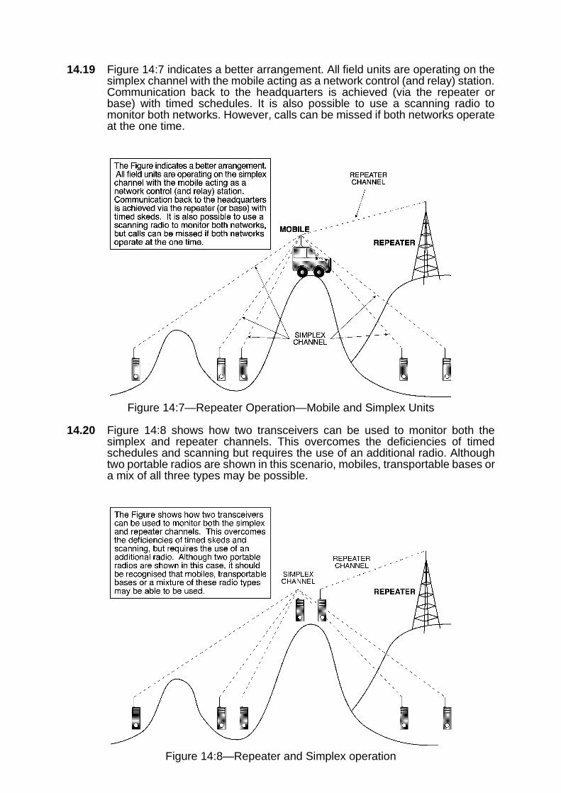
14.19 Figure 14:7 indicates a better arrangement. All field units are operating on thesimplex channel with the mobile acting as a network control (and relay) station.Communication back to the headquarters is achieved (via the repeater orbase) with timed schedules. It is also possible to use a scanning radio tomonitor both networks. However, calls can be missed if both networks operateat the one time.
Figure 14:7—Repeater Operation—Mobile and Simplex Units
14.20 Figure 14:8 shows how two transceivers can be used to monitor both thesimplex and repeater channels. This overcomes the deficiencies of timedschedules and scanning but requires the use of an additional radio. Althoughtwo portable radios are shown in this scenario, mobiles, transportable bases ora mix of all three types may be possible.
Figure 14:8—Repeater and Simplex operation

14.21 Figure 14:9 demonstrates a further mix of networks. The field units are able tocommunicate via a simplex network (VHF, UHF or 27Mhz) while the rear linkto HQ is achieved via HF radio. The HF link can operate in ground wave or skywave modes.
Figure 14:9—Repeater and Simplex Operation—HF Rear Link
14.22 Figure 14:10 indicates how two or more field networks operating on differentchannels (eg SES and Police) can be coordinated from a properly sited fieldEmergency Operations Centre. Another channel is used for rear linkcommunications to the major headquarters. Messages that need to be sent bytelephone can often be relayed to the major headquarters for action.
Figure 14:10—Field Networks on Different Channels
FIELD COMMUNICATIONS EQUIPMENT MANAGEMENT 14.23
14.23 The correct management of batteries, stores and allocation of priorities in thefield will help to ensure the effectiveness of command and control duringoperations. Irrespective of the quality of planning and the communicationsavailable, the operation could fail if sound communication managementtechniques are not adopted at the outset.
14.24 BATTERY MANAGEMENT
Battery management assumes high importance during operations. A qualifiedperson must be appointed before the start of the operation to manage thebatteries; their primary task must be battery management. Battery issue tooperators, receipt and charging should be carried out at a central location,located in the vicinity of the operations centre.
14.25 Replacement of batteries should occur at the end of the day or the completionof a shift, so that the opportunity can be taken to recharge the batteries. Thisopportunity also allows the communications manager to re-allocate radios toother operators if operational priorities change. Adequate stocks of all batterytypes in use must be available for the operation.
14.26 Conditioning of NiCad batteries is a process of charge/discharge cycles, whichhelp maintain batteries near peak capacity. Conditioning should be carried outon batteries when new and before they are placed into service. Manufacturersprovide details on battery conditioning. Full conditioning is a time consumingprocess and should be carried out in a workshop or controlled environment.


SECTION 3—EMERGENCY/DISASTER COMMUNICATIONS MANAGEMENT
CHAPTER 15
MISCELLANEOUS COMMUNICATIONS ISSUES CHAPTER 15
COMMUNICATION SURVEYS 15.1
15.1 On completion of the installation of a fixed radio communications system, aradio survey should be conducted to provide operational managers withdetailed knowledge of the area coverage available. Although the task islabour-intensive, the results obtained will ensure communications are moreeffective by identifying areas where difficulties could be expected.
15.2 SURVEY TECHNIQUE
The survey technique is simple. Field operators are given a map or an overlayand are sent into a specific area. At pre-determined distances the field operatorcalls the base and receives a signal report. If signals are readable, a green dotis placed on the map at the operator’s position. If signals are unreadable, a reddot is placed on the map.
15.3 PERFORMANCE MAPS
The process is repeated until the area specified has been adequately covered.When the operators return to base, information from the individual maps istranscribed to a master map. Over a period of time, a signal performanceprofile of the area is built up, clearly identifying the areas where goodcommunications are possible as well as identifying trouble spots.
15.4 EQUIPMENT PERFORMANCE VARIATIONS
Caution must be exercised to ensure that equipment being used is in goodworking order. When system upgrades take place the survey needs to berepeated.
15.5 Variations are also possible. One map may show hand-held performance,another manpack performance, while yet another may show mobiletransceiver results. Different signal levels may be shown by the use ofadditional coloured dots.
15.6 SETTING PRIORITIES
The task is obviously labour-intensive and priorities should be set to undertakethe task so that some useful data is available early in the process. For example,areas where activations occur frequently should be tested first. Suspected poorperformance areas may be surveyed next and so on. Surveys can be done inconjunction with other field activities.
15.7 BENEFIT
Although considerable effort is required to complete the survey, the resultsgained will help operational communications run more smoothly by identifyingcommunication difficulties ahead of time.

PUBLIC INFORMATION 15.8
15.8 Disaster-affected communities have a need to receive information relevant totheir circumstances. In the absence of such information, rumors may aboundand consequent difficulties may be experienced.
15.9 DISSEMINATION
If the normal media outlets, ie TV, radio and newspapers, are either notavailable or do not provide sufficient relevant detail, other methods will beneeded by the affected communities. Printed media in the form of newslettersor newspapers can be used to good effect in providing public information todisaster-effected communities. As a general rule, media liaison officers areappointed to ensure that information is effectively disseminated to the public.
LICENSING OF RADIO TRANSCEIVERS 15.10
15.10 The radio spectrum is a limited resource, with high commercial value to anycommunity or country. The spectrum is organised into an internationalmanagement system which allows responsible use by radio operators.Australia is a member of the International Telecommunications Union (ITU)and abides by its rulings.
15.11 MANAGEMENT
The licensing arrangements within Australia are managed and controlled bythe Australian Communications Authority (ACA) and the resource is providedon a ‘user pays’ principle. The provision and use of the radio spectrum ischarged at various rates dependent upon services provided.
15.12 Radio transceivers must be operated in accordance with the relevantregulations and licensing requirements. Severe penalties apply to illegalusers of the radio spectrum.


