25
Page 1 of 25 Version 4.0 July, 2005 Compact DC Power System M Series Compact Shelf 24 x7 Installation and Technical Support 1-866-240-6614

Page 1 of 25 Version 4.0 July, 2005
Compact DC Power System
M Series Compact Shelf
24 x7 Installation and Technical Support 1-866-240-6614

Page 2 of 25 Version 4.0 July, 2005
Table of Contents 1 Safety and Recommended Practices .................................................... 3
1.1 General practices................................................................................................. 3 1.2 FCC Compliance Statement................................................................................ 4
2 Product Section ...................................................................................... 5 2.1 Heat Dissipation.................................................................................................. 5 2.2 AC Requirements................................................................................................ 6 2.3 DC Circuit Drawings ........................................................................................ 13 2.4 DC output wire sizing ....................................................................................... 14 2.5 Torque settings.................................................................................................. 16
3 Required Tools ..................................................................................... 16
4 Site and Equipment Preparation........................................................ 16
5 Power Plant Mounting and Wiring.................................................... 16 5.1 Mechanical mounting........................................................................................ 16 5.2 AC input............................................................................................................ 17 5.3 DC output.......................................................................................................... 19 5.4 DC Reference ground ....................................................................................... 20 5.5 Alarms and control............................................................................................ 21
6 Test and Turn-Up ................................................................................ 23 6.1 Power up ........................................................................................................... 23
7 Troubleshooting ................................................................................... 24 7.1 Problems and Solutions..................................................................................... 24 7.2 Short circuit & Current Limit ........................................................................... 24
8 Installationsanleitung (German Installation).................................... 25

Page 3 of 25 Version 4.0 July, 2005
1 Safety and Recommended Practices
1.1 General practices For use in restricted access locations only.
Suitable for mounting on concrete or other non-combustible surfaces
This product accepts a nominal AC voltage between 100 and 240 VAC (±10%), 47 to 63 Hz, and produces a regulated output of 10.5-14VDC, 21-28 VDC, or 42-56 VDC (depending upon deployed rectifiers) capable of delivering a max of 300 Amperes DC for 12 V rectifiers, max of 300 Amperes DC for 24 V rectifiers, or max 250 Amperes DC for 48V rectifiers at an ambient operating temperature range of -40oC to +75oC (depending upon deployed rectifiers). HAZARDOUS VOLTAGE AND ENERGY LEVELS ARE PRESENT WHICH CAN PRODUCE SERIOUS SHOCKS AND BURNS. Only authorized, qualified, and trained personnel should attempt to work on this equipment. Refer to datasheets for full product specifications.
Observe all local and national electrical, environmental, and workplace codes.
Each power shelf should be fed from a dedicated AC branch circuit of a TN power system.
If a line cord(s) is (are) used as the AC connection means, the plug end of the cord is considered to be the primary disconnect means, and reasonable access must be given to the plug and receptacle area. The receptacle must be fed with a breaker or fuse according to Table 5 (12 V), Table 6 (24 V), or Table 7 (48V).
For hard-wired AC connections, a readily accessible disconnect device shall be incorporated in the building installation wiring. Select a wall breaker
and wire sizes according to Table 5 (12V), Table 6 (24V), or Table 7 (48V).
CAUTION: ALL RECTIFIERS EMPLOY INTERNAL DOUBLE POLE/NEUTRAL FUSING Internal rectifier fuses are not field accessible. They can be replaced only by authorized factory service personnel.
WARNING: HIGH LEAKAGE CURRENT: EARTH CONNECTION ESSENTIAL BEFORE CONNECTING SUPPLY
Use double hole, UL listed lugs for all DC connections to prevent lug rotation and inadvertent contact with other circuits. Terminal strip connections require only single hole lugs.
Class 1, 90°C wire is recommended for all DC connections. Minimum wire sizes are shown in Table 9. In practice, loop voltage drop considerations will usually dictate larger than minimum safe wire size. Connections to multiple loads are recommended to be made through an external distribution with over-current protection.
The alarm contacts are rated for a maximum voltage of 60 V, SELV (Safety Extra Low Voltage) and a maximum continuous current of .5A.
Connection and mounting torque requirements are listed in Table 11
Valere does not recommend shipping the power shelf with the rectifiers installed. Rectifiers should be shipped in separate boxes provided by Valere Power.

Page 4 of 25 Version 4.0 July, 2005
1.2 FCC Compliance Statement
1.2.1 Note
This device complies with Part 15 of FCC Rules. Operation is subject to the following two conditions:
1. This device may not cause harmful interference, and 2. This device must accept any interference received, including interference that
may cause undesired operation.
This equipment has been tested and found to comply with the limits for a Class B digital device, pursuant to Part 15 of the FCC Rules. These limits are designed to provide reasonable protection against harmful interference in a residential installation. This equipment generates, uses, and can radiate radio frequency energy and, if not installed and used in accordance with the instructions, may cause harmful interference to radio communications. However, there is no guarantee that interference will not occur in a particular installation.
If this equipment does cause harmful interference to radio or television reception, which can be determined by turning the equipment off and on, the user is encouraged to try to correct the interference by one or more of the following measures: -- Reorient or relocate the receiving antenna. -- Increase the separation between the equipment and receiver. -- Connect the equipment into an outlet on a circuit different from that to which the receiver is connected. -- Consult the dealer or an experienced radio/TV technician for help.
1.2.2 Warning
Changes or modifications to this unit not expressly approved by the party responsible for the compliance could void the user's authority to operate this equipment.
1.2.3 ICES-003 Class B Notice
This Class B digital apparatus complies with Canadian ICES-003. Cet appareil numérique de la classe B est conforme à la norme NMB-003 du Canada.

Page 5 of 25 Version 4.0 July, 2005
2 Product Section
2.1 Heat Dissipation
Table 1,Table 2, and Table 3 display the max and typical BTU/hr of heat dissipated for each rectifier. Max is calculated at minimum AC input voltages, Max Vdc and current values for rectifier, and typical is calculated at 240 Vac, typical Vdc, and rated current values.
Model Typical BTU/hr
Max BTU/hr
V500C 413 490V750C 619 718
Table 1 - Heat Dissipation (12 V Rectifiers)
Model Typical BTU/hr
Max BTU/hr
V500B 247 308V1000B 493 602V1500B 740 882
Table 2 - Heat Dissipation (24 V Rectifiers)
Model Typical BTU/hr
Max BTU/hr
V0250 90 153V0500A 180 281V1000A 361 563V1250A 451 690V1500A 541 844V2000A 722 1100V2500A 902 1355
Table 3 - Heat Dissipation (48 V Rectifiers)
Page 6 of 25 Version 4.0 July, 2005
2.2 AC Requirements
2.2.1 AC input circuit breaker sizing
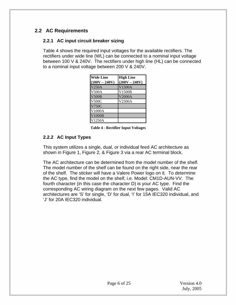
Table 4 shows the required input voltages for the available rectifiers. The rectifiers under wide line (WL) can be connected to a nominal input voltage between 100 V & 240V. The rectifiers under high line (HL) can be connected to a nominal input voltage between 200 V & 240V.
Wide Line (100V – 240V)
High Line (200V – 240V)
V250A V1500AV500A V1500BV500B V2000AV500C V2500AV750CV1000AV1000BV1250A Table 4 - Rectifier Input Voltages
2.2.2 AC Input Types
This system utilizes a single, dual, or individual feed AC architecture as shown in Figure 1, Figure 2, & Figure 3 via a rear AC terminal block.
The AC architecture can be determined from the model number of the shelf. The model number of the shelf can be found on the right side, near the rear of the shelf. The sticker will have a Valere Power logo on it. To determine the AC type, find the model on the shelf, i.e. Model: CM1D-AUN-VV. The fourth character (in this case the character D) is your AC type. Find the corresponding AC wiring diagram on the next few pages. Valid AC architectures are ‘S’ for single, ‘D’ for dual, ‘I’ for 15A IEC320 individual, and ‘J’ for 20A IEC320 individual.

Page 7 of 25 Version 4.0 July, 2005
2.2.2.1 Single Feed
Rectifiers
0 1 2 3 4
Feed 1AC In
N+1 DC Out
Figure 1 - Single Feed AC Wiring Architecture
A single feed architecture powers all five rectifiers with a single AC feed. Connect the feed, sized according to section 2.2.3, onto single #8-32 screws, and the ground will be connected to double, ¼”-20 studs as seen in Figure 7. For systems without Valere Power provided AC cords, choose AC ring terminals from section 2.2.4. The AC terminal strip on the rear of the shelf will accept ring terminals of less than 0.5” wide. Two, ¾” knockouts are provided for cable entry to the AC block.
Page 8 of 25 Version 4.0 July, 2005
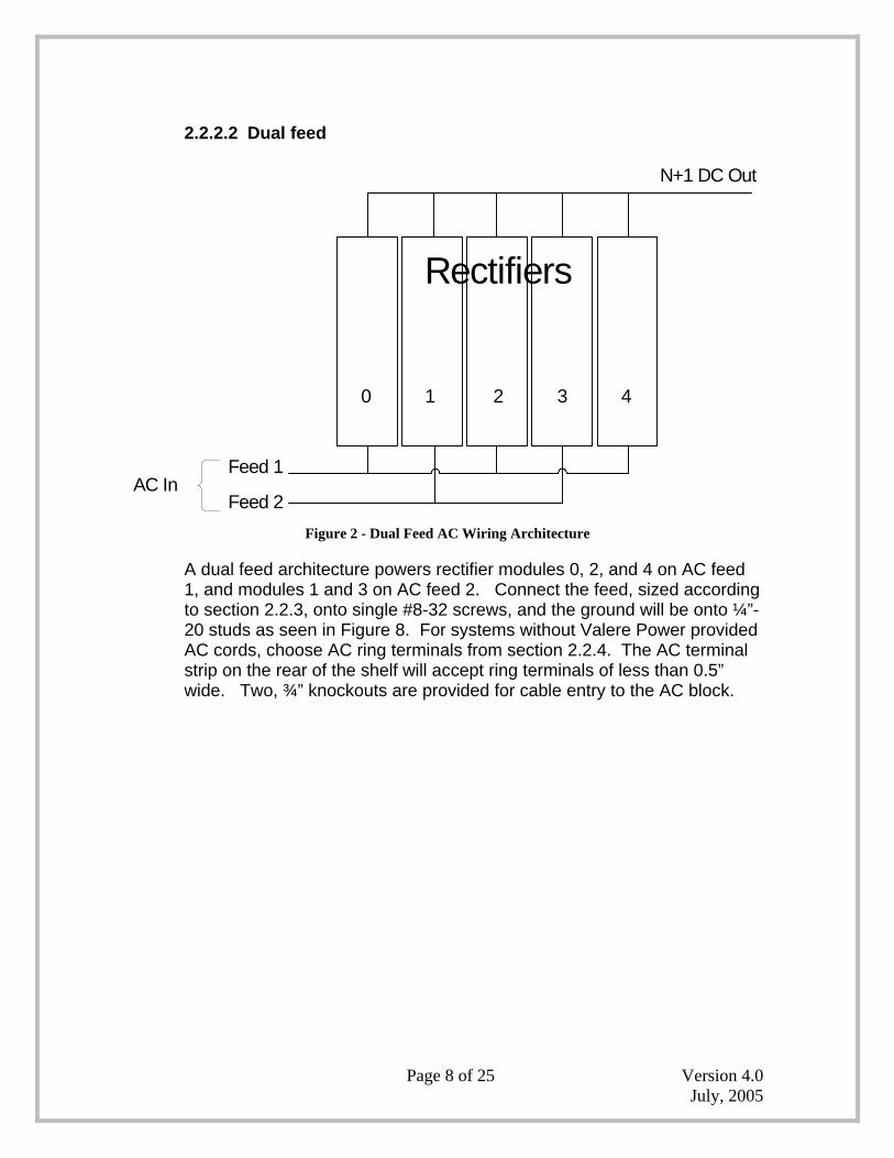
2.2.2.2 Dual feed
Rectifiers
0 1 2 3 4
Feed 1
Feed 2AC In
N+1 DC Out
Figure 2 - Dual Feed AC Wiring Architecture
A dual feed architecture powers rectifier modules 0, 2, and 4 on AC feed 1, and modules 1 and 3 on AC feed 2. Connect the feed, sized according to section 2.2.3, onto single #8-32 screws, and the ground will be onto ¼”-20 studs as seen in Figure 8. For systems without Valere Power provided AC cords, choose AC ring terminals from section 2.2.4. The AC terminal strip on the rear of the shelf will accept ring terminals of less than 0.5” wide. Two, ¾” knockouts are provided for cable entry to the AC block.

Page 9 of 25 Version 4.0 July, 2005
Rectifiers
0 1 2 3 4
Feed 1
Feed 2Feed 3Feed 4Feed 5
AC In
N+1 DC Out
Figure 3 - Individual Feed AC Wiring Architecture
An individual feed architecture powers one rectifier slot per AC feed. Connect the feed, sized according to section 2.2.3, into IEC320 plugs as seen in Figure 9. There are two different types of individual AC feeds. The first type of AC connection is made with IEC320 connectors that are rated for a maximum of 15 amps. Do not connect this type of individual AC system to an AC breaker larger than 15 amps. The second type of AC connection is made with IEC320 connectors that are rated for a maximum of 20 amps. Do not connect this type of individual AC system to an AC breaker larger than 20 amps. See section 2.2.2 for help determining your AC architecture type.
2.2.3 Sizing AC feeds
To size your AC feeds properly, use Table 5, Table 6, and Table 7. Failure to size the AC breaker and wiring properly can result in nuisance breaker trips or even damage to the equipment.
Follow the example below for determining AC breaker and wire sizing.
Use section 2.2.2 to determine the AC input type, for example a dual feed. Next determine the number and model number of the rectifiers, for example two V1250A (48V, 25A). Use Table 4 to determine the required AC input voltage. The V1250A rectifier will accept either low line or high line AC voltage, therefore following Table 7, this system will require two 20 amp

Page 10 of 25 Version 4.0 July, 2005
breakers with 12 AWG wire at low line, or two 15 amp breakers with 14 AWG wire at high line.
The tables in this section use the absolute minimum input voltage at which the rectifiers will run at to determine AC requirements. 90 V corresponds to low line and 180 V corresponds to high line.
V0500C 90 6.7 15 14V0500C 180 3.5 15 14V0750C 90 10.0 15 14V0750C 180 5.2 15 14V0500C 90 13.5 15 14V0500C 180 6.9 15 14V0750C 90 20.0 20 12V0750C 180 10.4 15 14V0500C 90 20.2 30 10V0500C 180 10.4 15 14V0750C 90 30.0 30 10V0750C 180 15.6 20 12V0500C 90 26.9 30 10V0500C 180 13.9 15 14V0750C 90 40.0 50 8V0750C 180 20.8 30 10V0500C 90 33.7 50 8V0500C 180 17.3 20 12V0750C 90 50.0 50 8V0750C 180 26.0 30 10
Circuit breaker
minimum value to use
90 °C Minimum Wire Gauge to use at 30 °C ambient
(AWG)
Number of Rectifiers
on AC Feed
Minimum Input
Voltage
Model Number of Rectifier
2
3
4
Maximum rated AC Current
(A)
Single AC feed
Fully Equipped Shelf
Individual AC feed
Dual AC feed
5
1
Table 5 - Recommended AC Circuit Breaker and Wire Sizes (12V system)

Page 11 of 25 Version 4.0 July, 2005
V0500B 90 7.6 15 14V0500B 180 3.8 15 14V1000B 90 14.6 15 14V1000B 180 7.3 15 14V1500B 180 11.2 15 14V0500B 90 15.0 15 14V0500B 180 7.5 15 14V1000B 90 29.2 30 10V1000B 180 14.6 20 12V1500B 180 22.3 30 10V0500B 90 22.7 30 10V0500B 180 11.3 15 14V1000B 90 43.8 50 8V1000B 180 21.9 30 10V1500B 180 33.5 50 8V0500B 90 30.2 30 10V0500B 180 15.0 15 14V1000B 90 58.4 75 6V1000B 180 29.1 30 10V1500B 180 44.7 50 8V0500B 90 37.8 50 8V0500B 180 18.8 20 12V1000B 90 73.0 75 6V1000B 180 36.4 50 8V1500B 180 55.9 75 6
Maximum rated AC
Current (A)
Circuit breaker minimum value
to use (A)
5
2
3
Single AC feed
Dual AC feed
Fully Equipped Shelf
4
Individual AC feed
90 °C Minimum Wire Gauge to use at 30 °C ambient
(AWG)
Number of Rectifiers on AC
Feed
Minimum Input
Voltage
1
Model Number of Rectifier
Table 6 - Recommended AC Circuit Breaker and Wire Sizes (24V system)

Page 12 of 25 Version 4.0 July, 2005
Fully Equipped Shelf
Number of Rectifiers on AC Feed
Model Number of Rectifier
Minimum Input Voltage
Maximum rated AC Current (A)
Circuit breaker minimum value to use (A)
90 °C Minimum Wire Gauge to use at 30 °C ambient (AWG)
V0250A 90 4.0 15 14
V0250A 180 2.1 15 14V0500A 90 7.4 15 14V0500A 180 3.7 15 14V1000A 90 14.6 15 14V1000A 180 7.3 15 14V1250A 90 17.8 20 12V1250A 180 9.1 15 14V1500A 180 10.9 15 14V2000A 180 14.6 15 14V2500A 180 18.2 20 12V0250A 90 8.0 15 14V0250A 180 4.1 15 14V0500A 90 14.8 15 14V0500A 180 7.4 15 14V1000A 90 29.2 30 10V1000A 180 14.6 15 14V1250A 90 35.7 50 8V1250A 180 18.2 20 12V1500A 180 21.9 30 10V2000A 180 29.1 30 10V2500A 180 36.4 50 8V0250A 90 12.0 15 14V0250A 180 6.2 15 14V0500A 90 22.1 30 10V0500A 180 11.0 15 14V1000A 90 43.8 50 8V1000A 180 21.9 30 10V1250A 90 53.5 75 6V1250A 180 27.3 30 10V1500A 180 32.8 50 8V2000A 180 43.7 50 8V2500A 180 54.6 75 6V0250A 90 16.0 20 12V0250A 180 8.2 15 14V0500A 90 29.5 30 10V0500A 180 14.7 15 14V1000A 90 58.4 75 6V1000A 180 29.1 30 10V1250A 90 71.3 75 6V1250A 180 36.4 50 8V1500A 180 43.7 50 8V2000A 180 58.3 75 6V2500A 180 72.8 75 6V0250A 90 20.0 20 12V0250A 180 10.3 15 14V0500A 90 36.9 50 8V0500A 180 18.4 20 12V1000A 90 73.0 75 6V1000A 180 36.4 50 8V1250A 90 89.1 90 4V1250A 180 45.5 50 8V1500A 180 54.6 75 6V2000A 180 72.8 75 6V2500A 180 89.1 90 4
1
2
Single AC Feed
Individual AC Feed
Dual AC Feed 3
4
5
Table 7 - Recommended AC Circuit Breaker and Wire Sizes (48V system)
Page 13 of 25 Version 4.0 July, 2005
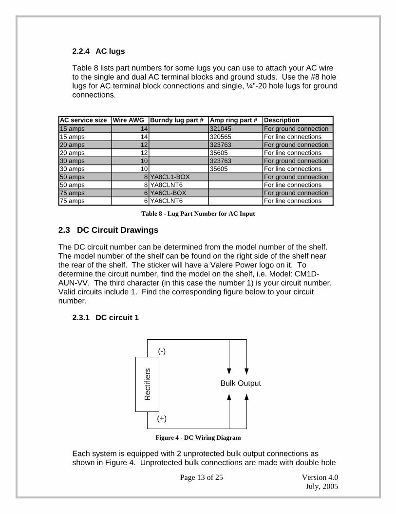
2.2.4 AC lugs
Table 8 lists part numbers for some lugs you can use to attach your AC wire to the single and dual AC terminal blocks and ground studs. Use the #8 hole lugs for AC terminal block connections and single, ¼”-20 hole lugs for ground connections.
AC service size Wire AWG Burndy lug part # Amp ring part # Description15 amps 14 321045 For ground connection15 amps 14 320565 For line connections20 amps 12 323763 For ground connection20 amps 12 35605 For line connections30 amps 10 323763 For ground connection30 amps 10 35605 For line connections50 amps 8 YA8CL1-BOX For ground connection50 amps 8 YA8CLNT6 For line connections75 amps 6 YA6CL-BOX For ground connection75 amps 6 YA6CLNT6 For line connections
Table 8 - Lug Part Number for AC Input
2.3 DC Circuit Drawings
The DC circuit number can be determined from the model number of the shelf. The model number of the shelf can be found on the right side of the shelf near the rear of the shelf. The sticker will have a Valere Power logo on it. To determine the circuit number, find the model on the shelf, i.e. Model: CM1D-AUN-VV. The third character (in this case the number 1) is your circuit number. Valid circuits include 1. Find the corresponding figure below to your circuit number.
2.3.1 DC circuit 1
Rec
tifie
rs
Bulk Output
(-)
(+)
Figure 4 - DC Wiring Diagram
Each system is equipped with 2 unprotected bulk output connections as shown in Figure 4. Unprotected bulk connections are made with double hole

Page 14 of 25 Version 4.0 July, 2005
lugs on ¼”-20 studs with 5/8” centers. The maximum tongue width for bulk connections is a lug at 0.68”. Select a wire size for the bulk outputs according to the current rating as shown in Table 9. Choose lugs and ring terminals according to section 2.4.2.
2.3.2 DC reference ground
The Valere Power system is a fully floating system. This means that the output bus bars are not tied to the chassis or an earth ground. An external reference or earth ground may be connected to either output bus bar based on the desired polarity of your system. The connection is double ¼”-20 studs with 5/8” centers. As always follow your company’s guidelines for sizing and attaching a reference ground.
2.4 DC output wire sizing
There are two main considerations for sizing DC wire; ampacity and voltage drop. Ampacity refers to a safe current carrying level as specified by non-profit organizations such as Underwriters Laboratories and the National Fire Prevention Association, which publishes the National Electric Code. Voltage drop is simply the amount of voltage loss in a length of wire due to ohmic resistance of the conductor. DC wire may be sized for either ampacity or voltage drop depending on branch load loop length and conductor heating. In general, ampacity considerations will drive wire selection for short loop lengths (less than 50 feet) and voltage drop will drive wire selection for long loop lengths (greater than 50 feet). The National Electric Code table 310.16 provides ampacity values for various sizes, bundles, and insulation temperature rated wire. ALWAYS FOLLOW NEC RULES AND YOUR LOCAL COMPANY PRACTICES WHEN SELECTING DC WIRING AND PROTECTION. Table 9 shows MAXIMUM recommended wire sizes.
2.4.1 DC cable sizing
Unprotected DC output wires shall be based on the total rectifier capacity of the shelf. For example, using Table 9 below, a system with four V2500A (48V, 50A) rectifiers for a total capacity of 200 A requires two #2 AWG wires.

Page 15 of 25 Version 4.0 July, 2005
Total rectifier Current Rating (A)
Wire & Lug Gauge (AWG) using 90° C wire (NEC Table 310.16)
5 18*10 16*15 1620 1430 1240 1050 875 6
100 2125 2150 (1) 1 AWG or (2) 6 AWG175 (2) 4 AWG200 (2) 2 AWG225 (2) 2 AWG250 (2) 2 AWG300 (2) 1 AWG
* - For wire sizes less than 15 A not covered in NEC Table 310.16 use Table 3B - Sizes of Conductors, UL60950, "Safety of Information Technology Equipment", Dec., 2000 for non-building wiring.
Table 9 - Minimum Recommended DC AWG for 90°C Cabling
2.4.2 DC lugs
Table 10 lists part numbers for some lugs you can use to attach your DC wires to the system. These lugs are based on flex style cable.
Wire AWG Burndy Lug Part # AMP Ring Part # Description16 AWG 321045 SH RING TERMINAL1/4 STUD14 AWG 321045 SH RING TERMINAL1/4 STUD12 AWG 323763 SH RING TERMINAL1/4 STUD10 AWG 323763 SH RING TERMINAL1/4 STUD
10 AWG YAV102TC14DH LUG STANDARD BARREL 1/4 STUD,5/8 CENTER
8 AWG YA8CL2TC14DH LUG STANDARD BARREL 1/4 STUD,5/8 CENTER
6 AWG YAV6CL2TC14FXDH LUG STANDARD BARREL 1/4 STUD,5/8 CENTER
4 AWG YAV2CL2TC14FXDH LUG STANDARD BARREL 1/4 STUD,5/8 CENTER
2 AWG YAV2CL2TC14FXDH LUG STANDARD BARREL 1/4 STUD,5/8 CENTER
1 AWG YAV1CL2TC14FXDH LUG STANDARD BARREL 1/4 STUD,5/8 CENTER
Table 10 - Lug Part Number for DC Output

Page 16 of 25 Version 4.0 July, 2005
2.5 Torque settings
Table 11 shows the recommended torque settings for all mechanical and electrical connections according to screw or nut size. Not all screw sizes may be present on a particular shelf.
Screw or Nut Size
Torque (in-lbs)
4-40 66-32 128-32 22
10-32 3712-24 50¼-20 65
Table 11 - Recommended Torque Settings
3 Required Tools
Valere rectifiers are designed to be installed with a minimum number of commonly available tools.
• #1 & #2 Phillips screwdrivers • Torque wrench • 5/16” or 7/16” box wrenches, sockets, or nut drivers • Wire and Cable Strippers • Wire and Cable Crimpers
4 Site and Equipment Preparation
After removing DC Power Plant from boxes and packing material, inspect for shipping and/or other damage. Contact sales (1-877-VALERE1) or technical support (1-866-240-6614) immediately if any damage is present. Have all tools, wire, cables, hardware, etc., within easy reach. To the extent possible ensure a clean (free of debris, dust, foreign material, etc.) work environment. Ensure all AC and DC power sources are off and disconnected.
5 Power Plant Mounting and Wiring
5.1 Mechanical mounting
This equipment is intended for normal operations and is to be installed in a standard 19” telecommunications rack. It is recommended that one person lift the shelf into place while another installs supplied mounting hardware. Torque mounting hardware according to Table 11. This shelf contains built in air baffles that redirect airflow horizontally. Because of these built in baffles, no extra space
Page 17 of 25 Version 4.0 July, 2005
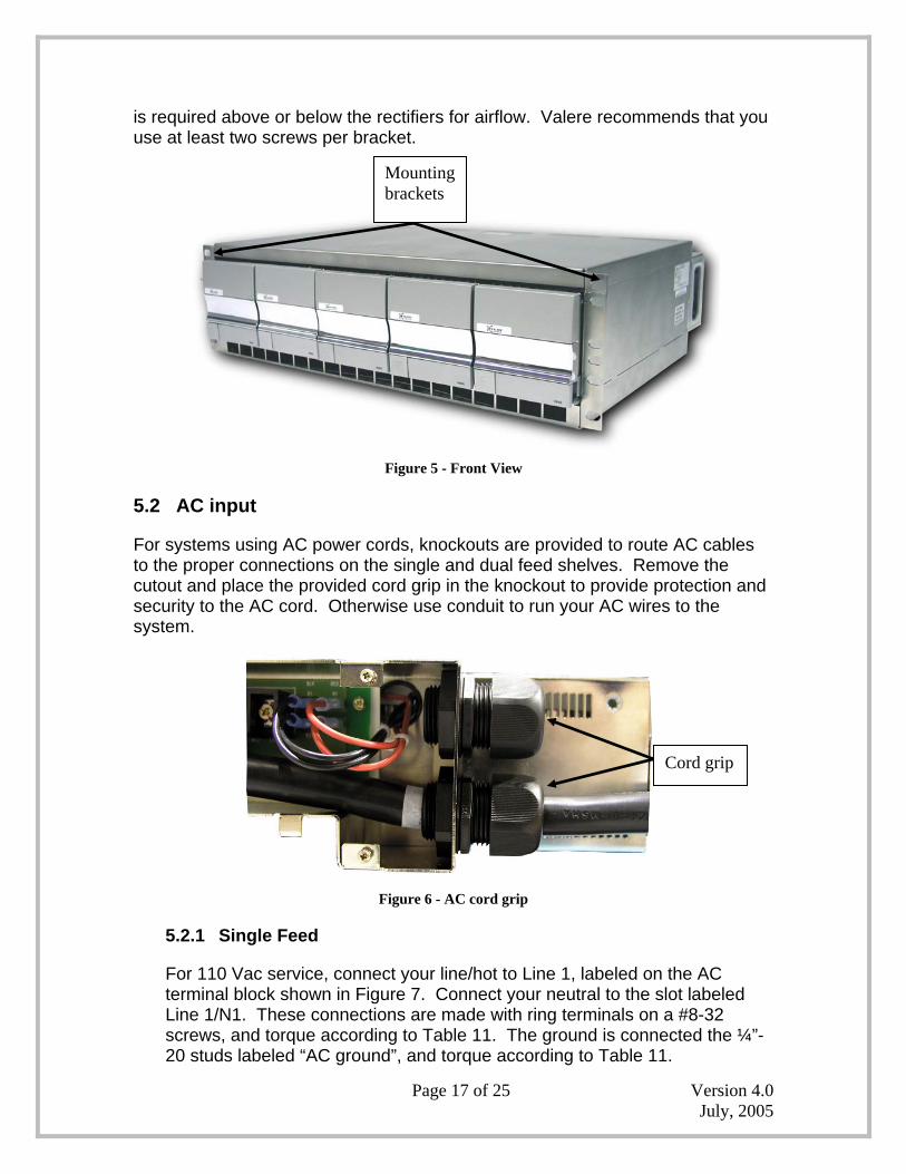
is required above or below the rectifiers for airflow. Valere recommends that you use at least two screws per bracket.
Figure 5 - Front View
5.2 AC input
For systems using AC power cords, knockouts are provided to route AC cables to the proper connections on the single and dual feed shelves. Remove the cutout and place the provided cord grip in the knockout to provide protection and security to the AC cord. Otherwise use conduit to run your AC wires to the system.
Figure 6 - AC cord grip
5.2.1 Single Feed
For 110 Vac service, connect your line/hot to Line 1, labeled on the AC terminal block shown in Figure 7. Connect your neutral to the slot labeled Line 1/N1. These connections are made with ring terminals on a #8-32 screws, and torque according to Table 11. The ground is connected the ¼”-20 studs labeled “AC ground”, and torque according to Table 11.
Mounting brackets
Cord grip

Page 18 of 25 Version 4.0 July, 2005
For 208/220 Vac service, connect your line/hot to Line 1, labeled on the AC terminal block shown in Figure 7. Connect your second line/hot to the slot labeled Line 1/N1. These connections are made with ring terminals on a #8-32 screws, and torque according to Table 11. The ground is connected the ¼” stud labeled “AC ground”, and torque according to Table 11.
Figure 7 - Single AC feed
When ready to power up, plug in the AC cord into the proper receptacle or turn on the AC breaker.
5.2.2 Dual Feed
For 110 Vac service, connect your first line/hot to Line 1, labeled on the AC terminal block shown in Figure 8. Connect your neutral to the slot labeled Line 1/N1. For your second feed connect line/hot to the slot labeled Line 2. Connect your neutral to the slot labeled Line 2/N2. These connections are made with ring terminals on a #8-32 screws, and torque according to Table 11. Connect both grounds to the ¼” studs labeled “AC ground”, and torque according to Table 11.
For 208/220 Vac service, connect your first line/hot to Line 1, labeled on the AC terminal block shown in Figure 8. Connect your second line/hot to the slot labeled Line 1/N1. For your second feed connect line/hot to the slot labeled Line 2. Connect your second line/hot to the slot labeled Line 2/N2. These connections are made with ring terminals on a #8-32 screws, and torque according to Table 11. Connect both grounds to the ¼” studs labeled “AC ground”, and torque according to Table 11.
Line 1 Line 1/N1
2 – ¾” Knockouts AC ground

Page 19 of 25 Version 4.0 July, 2005
Figure 8 - Dual AC feed
When ready to power up, plug in the AC cord into the proper receptacle or turn on the AC breaker.
5.2.3 Individual Feed
For any AC service between 100 Vac to 240 Vac, connect each line cord into the appropriate AC receptacle on the rear on the shelf as seen in Figure 9.
Figure 9 - Individual AC feed (15 amp plugs shown)
When ready to power up, plug in the AC cord into the proper receptacle or turn on the AC breaker.
5.3 DC output
DC connections are accomplished via the two rear bulk output connections as shown in Figure 10. Connections are made with double hole lugs with ¼”-20 studs with 5/8” centers. Select wire and lug sizes according to Section 2.3.
2 – ¾” Knockouts
01234
Line 1 Line 1/N1 Line 2 Line 2/N2
AC ground

Page 20 of 25 Version 4.0 July, 2005
Figure 10 - DC Connections
Route DC cables out the side of the shelf through the cable routing holes seen in Figure 11.
Figure 11 - Cable routing holes
5.4 DC Reference ground
Connect your reference ground to either the negative output or positive output (Figure 10) depending on the desired polarity. The connection is double ¼”-20 studs with 5/8” centers.
DC Cable routing holes
Negative Output
Positive Output

Page 21 of 25 Version 4.0 July, 2005
5.5 Alarms and control
Access to alarms and control signals is accomplished via a rear mounted connector (p/n 43045-2019, Molex) as shown in Figure 12. Table 12 provides a pin functional description. • The pin out of the alarm connector on the shelf is a 180° difference from a
standard Molex connector. See Figure 11 & Figure 12. • AC fail, DC fail, and Thermal limit fail alarms are all open collector, opto-
coupled, active high on failure/active low normally (software or factory configurable), and referenced to pin 17. The pin is able to sink 10 mA of current at 5 V and 5 mA at TTL voltages.
• Applying 5 V between pins 16 and 17 will shut all rectifiers down. Removing the 5V will cause the rectifier to power back up.
Figure 12 - Alarm and signal connector on shelf
Figure 13 - Alarm cable pin out
110
1120
2011
1 10

Page 22 of 25 Version 4.0 July, 2005
J1 PIN WIRE COLOR Description
20 BLK Shelf Bias: A regulated 12V/100ma bias supply. Referenced to Pin 10.
19 RED SCL: I2C clock line. Referenced to Pin 10.18 RED/WHT SDA: I2C data line. Referenced to Pin 10.
17 RED/BLK Logic Ground: Isolated ground for opto-coupled alarms.
16 GRN/WHTModule Disable: Opto-coupled input.
Applying 5V between this pin and Pin 17 will disable all modules in the shelf.
15 LT BL Module 0 (leftmost slot) AC Fail.14 LT BL/WHT Module 1 AC Fail13 LT BL/BLK Module 2 AC Fail12 YLW/WHT Module 3 AC Fail11 YLW/BLK Module 4 (rightmost slot) AC Fail10 TAN/WHT V Main Output (-). DC power ground.
9 TAN/BLKI Shelf: Indicates average shelf current. Ratio
varies with rectifier type. Call factory for details.
8 TANV Margin: Applying a 0-5V signal from this pin to Pin 10 will linearly change the output
voltage by 0-10V.7 GRN/BLK Not Used6 GRN Module Thermal Limit Failure5 OR/WHT Module 0 (leftmost slot) DC Fail.4 OR/BLK Module 1 DC Fail3 OR Module 2 DC Fail2 WHT Module 3 DC Fail1 YLW Module 4 (rightmost slot) DC Fail
Table 12 - Alarm and Signal Interconnections

Page 23 of 25 Version 4.0 July, 2005
6 Test and Turn-Up
6.1 Power up
Once all AC and DC connections have been secured and checked, install each rectifier sequentially by sliding and latching each rectifier into a shelf position as shown in Figure 14. The rectifier latches must be open for installation. Attempting to install the rectifiers with the latches closed will result in mechanical damage to the rectifiers and the shelf. The rectifiers will start in high fan speed mode and reduce their speed according to the ambient and plant conditions within 10 seconds. The AC OK and DC OK LED’s will illuminate and the ALM LED will extinguish.
Figure 14 - Rectifier insertion

Page 24 of 25 Version 4.0 July, 2005
7 Troubleshooting
7.1 Problems and Solutions
The modular, plug-n-play nature of this plant makes diagnostics and repair very easy. Make sure that all rectifiers are properly seated and latched into their respective slots. Make sure that all power and signal connectors are properly mated. Table 13 lists problems and potential solutions.
Problem SolutionsDC OK LED Extinguished or Module DC Fail from alarm cable
Replace bad rectifier unit - unlatch, remove and replace with spare. System short circuit - inspect and replace load and wiring.
AC OK LED Extinguished or Module AC Fail from alarm cable
Reset commercial circuit breaker to the dedicated AC circuit that feeds system. Seek alternative power source until power is restored.
Thermal Limit Failure Rectifier has shut down because it has exceeded the maximum rated temperature. The rectifiers will automatically restart.
Table 13 - Problems and Solutions
7.2 Short circuit & Current Limit
ILimit can be adjusted up to +105% of the rated current of the rectifier. The system voltage will remain constant up to ILimit at which point the system voltage will drop quickly toward 0 Vdc , as in Figure 15. Once a 24V or 48V rectifier drops below 12 Vdc for more than 5 seconds, the system will shut down. For a 12V system, once the rectifier drops below 4V for more than 60 seconds, the system will shut down. The system will automatically restart after 60 seconds, and will continue until the short circuit is cleared.
Figure 15 - Short Circuit & Current Limit
ILimit Current
VRated
Rectifier Voltage
Vshutdown
Page 25 of 25 Version 4.0 July, 2005
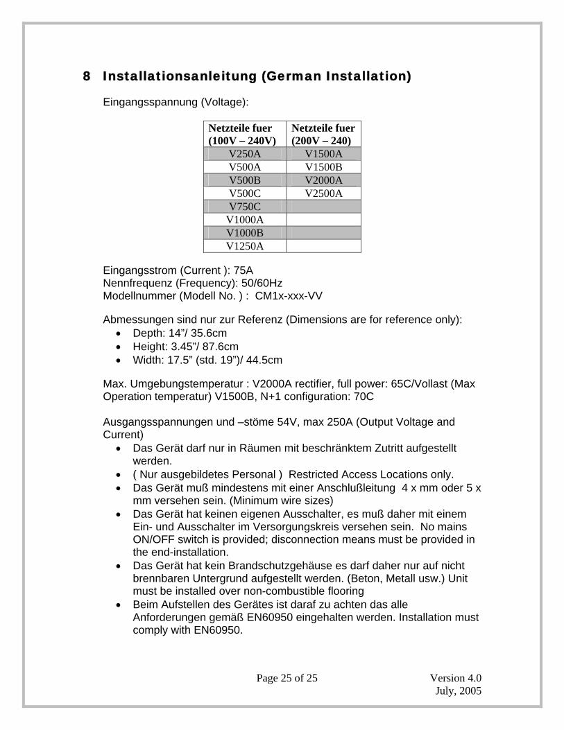
8 Installationsanleitung (German Installation)
Eingangsspannung (Voltage):
Netzteile fuer (100V – 240V)
Netzteile fuer (200V – 240)
V250A V1500A V500A V1500B V500B V2000A V500C V2500A V750C
V1000A V1000B V1250A
Eingangsstrom (Current ): 75A Nennfrequenz (Frequency): 50/60Hz Modellnummer (Modell No. ) : CM1x-xxx-VV
Abmessungen sind nur zur Referenz (Dimensions are for reference only): • Depth: 14”/ 35.6cm • Height: 3.45”/ 87.6cm • Width: 17.5” (std. 19”)/ 44.5cm
Max. Umgebungstemperatur : V2000A rectifier, full power: 65C/Vollast (Max Operation temperatur) V1500B, N+1 configuration: 70C Ausgangsspannungen und –stöme 54V, max 250A (Output Voltage and Current)
• Das Gerät darf nur in Räumen mit beschränktem Zutritt aufgestellt werden.
• ( Nur ausgebildetes Personal ) Restricted Access Locations only. • Das Gerät muß mindestens mit einer Anschlußleitung 4 x mm oder 5 x
mm versehen sein. (Minimum wire sizes) • Das Gerät hat keinen eigenen Ausschalter, es muß daher mit einem
Ein- und Ausschalter im Versorgungskreis versehen sein. No mains ON/OFF switch is provided; disconnection means must be provided in the end-installation.
• Das Gerät hat kein Brandschutzgehäuse es darf daher nur auf nicht brennbaren Untergrund aufgestellt werden. (Beton, Metall usw.) Unit must be installed over non-combustible flooring
• Beim Aufstellen des Gerätes ist daraf zu achten das alle Anforderungen gemäß EN60950 eingehalten werden. Installation must comply with EN60950.


