L. W. Blair* and C. J. RussotGeneral Electric Company, Lynn, Mass.
The smaller centrifugal compressor diameter of many advanced turbofan engines renders unattractive the useof conventional conical or channel diffusing systems to deliver low Mach number, low swirl flow to the com-bustor. A method has been developed for designing a set of low-diameter, radially-emanating, controlled-contour passage diffusers. Using this method, several such passages were designed and tested. Static pressure risecoefficients of 0.79-0.82 were obtained at throat blockages of 2-3% for an inlet Mach number of 0.7-0.8 and anexit Mach number of 0.10 with 5-10 deg of residual swirl within an outer diameter 20% smaller than con-ventional engines.
THE application of centrifugal compressors in turboshaftand turbofan engines may require small diffuser
diameters for lower weight and smaller frontal area. Con-ventional passage diffusers of circular or rectangular cross-section typically have large outlet diameters for exit Machnumbers below 0.20. The objective of this reported projectwas to lower the compressor diameter by wrapping the dif-fusing passages around a radial-to-axial turn while main-taining a high level of diffuser performance. This approachavoids dumping the flow into an annular turning duct withsignificant mixing and Mach number losses. The test programpresented herein evaluated some of the design variables whichwere deemed most significant in affecting passage per-formance. These designs considered potential engine ap-plications in the choice of .the range of parameters studied. Arequirement in these designs was the delivery of a low outletMach number (0.10) and swirl (0-15 deg) into a combustorplenum.
*Manager, T700 and Advanced Centrifugal Aerodynamic Design.fEngineer, Aerodynamic Design and Analysis.
The design of the low-diameter diffusers utilized ananalytical model to generate the passages which permitted adirect interface with interactive graphics (IAG) to generate thedetailed design definition. This analytical definition alsoallowed a systematic set of design variables to be in-dependently evaluated. These designs are called controiled-contour passages because the flowpath is defined by a smoothanalytical function. The cross-sectional shape of thesepassages can be smoothly varied (i.e., from circular to ellipticto rectangular). This analytic procedure is applied herein tocentrifugal compressors but is general and can be used todefine other shapes (i.e., engine inlets and external bodies).
In the present study, the performance of the controlled-contour diffuser passages were evaluated experimentally byblowing air through individual scaled-up passages varyingthroat blockage and Mach number over the range encounteredin engine conditions. Evaluating diffuser performance fromsingle passage blow tests does not include the effects ofphysical size, throat Reynolds number, nonuniform inletvelocity profiles, and high inlet turbulence levels. The effectsof the larger diffuser physical size and smaller throatReynolds number on diffuser performance were investigatedand reported in Ref. 1. In the study reported in Ref. 1,nonuniform inlet velocity profiles and high inlet turbulentintensities which are encountered in engine environments butnot simulated in the blow tests were found to effect only theinternal distribution of static pressure rise. The overall dif-fuser performance aft of the throat was found to be a func-tion only of throat blockage, Mach number, and Reynoldsnumber. Thus the single passage blow tests permitted theoptimization of the controlled-contour diffuser designs and
Fig. 1 Passage coordinate system.
Dow
nloa
ded
by U
NIV
ER
SIT
Y O
F Q
UE
EN
SLA
ND
on
June
2, 2
014
| http
://ar
c.ai
aa.o
rg |
DO
I: 1
0.25
14/3
.573
54
JANUARY 1982 COMPACT DIFFUSERS 47
also allowed detailed static pressure measurements and exittraverse surveys which are difficult to acquire in centrifugalstage tests.
II. Diffuser DesignA general approach for designing curved ducts in space was
defined which permitted independent specification of turning,area change, and cross-sectional shape. This design procedurerequired a definition of the passage centerline in space and apassage area distribution along this centerline. The passageinlet cross section can be either circular or rectangular foreither a conical or channel diffuser discharge. In the test seriespresented herein, circular inlet cross sections were in-vestigated. The projection in the meridional plane of thepassage centerline was an ellipse for all designs in this study(see Fig. 1). The ellipse aspect ratio (minor axis/major axis)was 0.666 with the major axis 0.75 times the inlet cross-section diameter. The centerline projection was continued in astraight line two inlet diameters downstream of the end of theellipse. Coordinates of the centerline in space can becalculated from the coordinates in the meridional plane, usingthe relationship for passage wrap angle given in the followingequation:
dO tan/3
The meridional distance m is the length of the projectedpassage centerline on the R-Z plane. The passage centerlineangle 0 determined the direction cosines of a plane whichcontained the passage cross sections and is distributeduniformly to avoid excessive rates of turning. This equationhas proved useful in the definition of radial turbomachinerygeometry and is discussed in Ref. 2. In this application, thepassage centerline angle |8 represents a mean flow angle. Thedistribution of this angle controls the rate of turning of thepassage where the fluid is turned from a radial to an axialflow direection while removing about 50-60 deg of swirl.
The passage cross sections are generated from the followingequation:
(x/a)en + (y/b)em =1 (2)
The exponents em and en determine the "rectangularity" ofthe perimeter or the "sharpness" of the corners from thevalue 2 (ellipse) to 8 or more (rectangular with corner fillet).The constants a and b are tne semimajor and semiminor axesof the cross section, as shown in Fig. 1. The centrifugal
compressor diffuser passage had the semiminor axis on aradial line, and the semimajor axis was an arc for an annularpassage discharge. The aspect ratio of the passage alb isadjusted to have at least twice the nominal wall thicknessbetween adjacent passages.
The design procedure using Eqs. (1) and (2) provided ananalytic definition of the entire duct. The design approachused high diffusion rates in the initial radial section tominimize the Mach number into the radial-to-axial turn. Theselected diffusion rate was below the transitory stall boundaryfor the expected 2-3% blockage in engine applications. Thepassage cross section was transformed from circular to ellipticbefore the radial-to-axial turn in order to reduce the turninglosses. The deswirl process was initiated near the exit of theradial-to-axial turn. Passage cross sections were generated tobe displayed on interactive graphics (IAG) and to preparetemplates for fabrication of test hardware.
The test program evaluated various design parameters in aseries of test configurations. These parameters were the1) rate of radial-to-axial turn; 2) inlet Mach number intoradial-to-axial turn; 3) circumferential deswirl rate and theinitial location of deswirling; 4) effect of passage splitters;5) rate of passage area increase; and 6) number of diffuserpassages.
A 61/2-deg cone was also fabricated to obtain baseline datafor comparison with other available test results and to verifythe adequacy of the test apparatus.
The six test models reported herein had the deswirldistributions shown in Fig. 2 and the area distributions shownin Fig. 3. The Mach number into the radial-to-axial turn was0.46 for designs 1, 2, and 4; 0.41 for design 3, and 0.27 fordesigns 5 and 6. The designs 1-5 subtended an arc equivalentto 33 diffuser passages and design 6 was 25 passages. Thesedesigns were tested with and without a splitter vane in the exitregion of the diffuser passage. In all designs tested the splitterwas placed in the center of the passage with the leading edge atthe exit of the radial-to-axial turn and extended over about45% of the true centerline length. Because of the large numberof design parameters, the ranges explored in this initial testseries were values deemed more significant for engine ap-plications.
In constructing the test series, designs 1 and 2 were identicalexcept that design 2 was shortened to have 15 deg of residualswirl. Design 3 had a higher initial rate of area increase, butwas identical to design 1 in other parameters. Design 4 had adeswirl distribution which decreased the rate of turning nearthe exit. Designs 5 and 6 had a higher initial rate of area in-crease similar to design 3 and evaluated the effect of 33 vs 25
PassageAngle (/?)
10
0.2 0.4 0.6 0.8 1.0Distance (L/Lt)
Fig. 2 Deswirl angle distribution.
0.2 0.4 0.6Distance (L/Lt)
Fig. 3 Passage area distribution.
0.8
Dow
nloa
ded
by U
NIV
ER
SIT
Y O
F Q
UE
EN
SLA
ND
on
June
2, 2
014
| http
://ar
c.ai
aa.o
rg |
DO
I: 1
0.25
14/3
.573
54
48 L. W, BLAIR AND C. J. RUSSO J. AIRCRAFT
Fig. 4 Strung box with cross section.
- Inlet Pipe Statics ASME Bellmouth
Diffuser ThroatStatics
Inlet Spacer
Fig. 5 Blow test rig.
passages. The initial passage centerline angle was 49.6 deg fordesigns 5 and 6, since it was closer to a proposed engineapplication.
III. Test ApparatusThe test models were constructed using a strung box
technique to position the various cross sections. This methodenclosed the test section with a box, and the axes of each crosssection were extended until they intercepted the inner walls ofthe box. The intercept points were determined on the IAGsystem, along with templates for manufacture of the box. Apair of fine wires were strung for each section, as shown inFig. 4. The wire diameter was considered in determining theintercept points. The sections were tied together and themaster passage was built up to form a smooth surface. Thispassage was reproduced in plaster to form a core for afiberglass test section. The model was molded with integralstatic pressure taps positioned at each cross section. Fourstatic pressure taps were used at each measurement plane: top,bottom, and each side wall.
The blow test apparatus for these diffuser tests is shown inFig. 5 for a typical setup. The inlet section was an elliptic-shaped ASME nozzle which provided an additional airflowmeasurement. Attached to the test section was a set of inletspacers which were used to vary the initial boundary-layerblockage into the test sections with the longest spacer 4 in.long. The inlet diameter was 0.80 in.
A hot-film X probe was used to measure the flow velocityand angle at the passage exit. The hot-film probe was a TSImodel 1240-60 cross-flow X probe which was calibrated forvelocity and angle. This probe was set at various immersions
Fig. 6 Blow test rig with hot-film probe.
0.90
Rise Coefficient
O.SO
I !I _ . Dolan & Runstadler
= 0.80 Re = I.71 X1
6.5° Cone
Diffuser
A 1D 20 3• 4O 50 6
^/
£
\
4
O*
O
(i
0.86 0.88 0.90 0.92 0.94 0.96 0.98 1.
Diffuser Throat Blockage (1 — Bt)
Fig. 7 Diffuser performance vs throat blockage at Red=4.3xW5
and M= 0.80.
and traversed across the passage to determine the flow profile.The hot-film probe is shown in position in Fig. 6.
IV. Test Results and AnalysisA straight, 6!/2-deg cone was the first diffuser blow-tested
in order to verify the symmetry of the flow entering thediffuser and to verify the calculated blockage which assumedno total pressure loss from the inlet-pipe static pressure tapsto the diff user-throat static pressure taps (see Fig. 5). Thus atthe diffuser throat the total pressure, static pressure, weightflow, geometric area, and temperature are known, and theMach number and blockage can be calculated from com-pressible flow equations, assuming no circumferential flowcomponent exists. This calculation procedure is identical tothat of Dolan and Runstadler (Ref. 3) and the blow-testmeasured static pressure rise coefficient is in excellentagreement with their measured results, as shown in Fig. 7. Theerror bars on the Dolan and Runstadler data reflect thevariation in blockage given in their report.
As in the Dolan and Runstadler study, the controlled-contour diffuser performance was measured as a function ofthroat Mach number with each inlet spacer (but at only oneReynolds number). Figure 8 shows typical results. Hidden inthese results is any variation of throat blockage with throat
Dow
nloa
ded
by U
NIV
ER
SIT
Y O
F Q
UE
EN
SLA
ND
on
June
2, 2
014
| http
://ar
c.ai
aa.o
rg |
DO
I: 1
0.25
14/3
.573
54
JANUARY 1982 COMPACT DIFFUSERS 49
Static Pressure o.72Rise Coefficient
0.86
0.82
0.68
U.DO
0.64
L
0 °
ngest S
0
O
0
0
pacer —
<><*><
o
0
o o
-<.\
\ <^
o
S
0
0 °
^NoSp
0
0 0
0 < .
jeer
*
oc
0
0
>
1°
D
0<
% o
' 00
o
10 Design 60 6-1/2° Cone
0 o0.1 0.2 0.3 0.4 0.5 0.6 0.7 0.8 0.9 1.0 1.1
Throat Mach Number
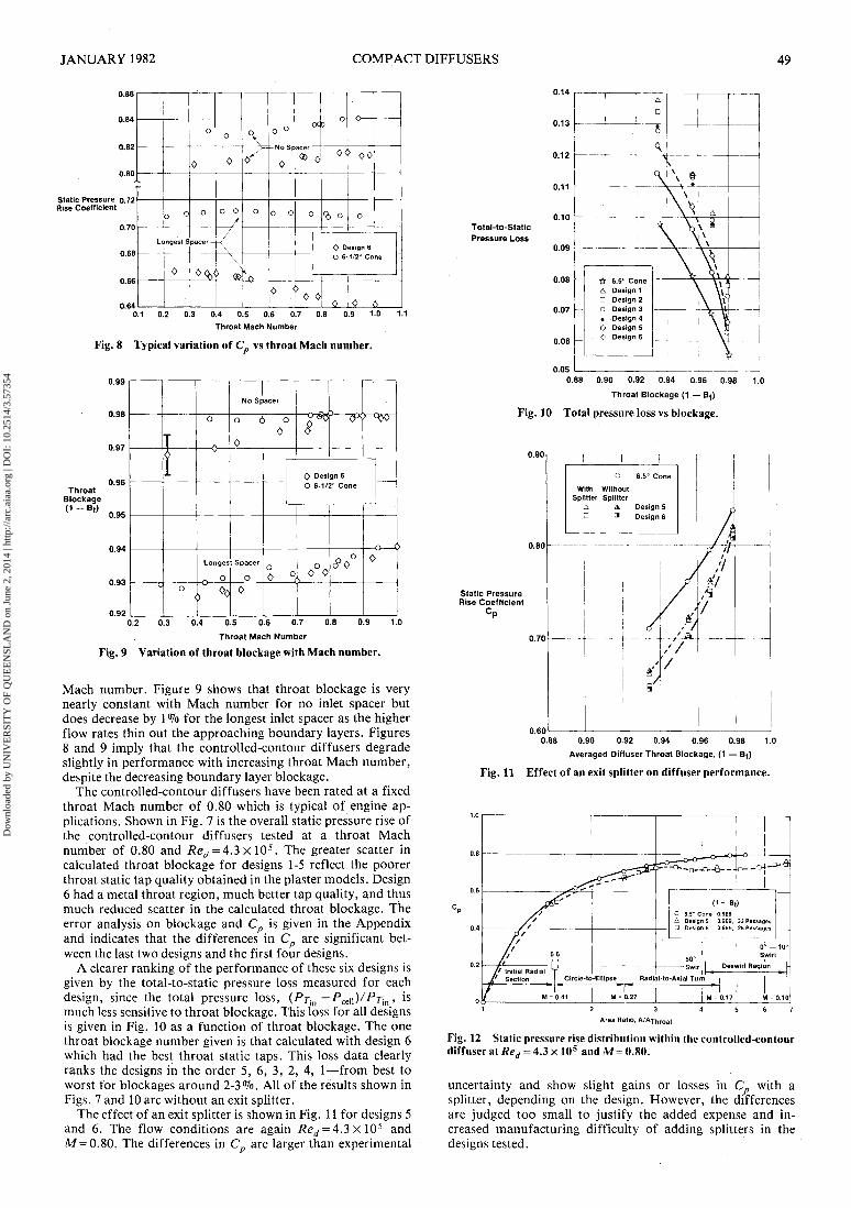
Fig. 8 Typical variation of C vs throat Mach number.
Fig. 9 Variation of throat blockage with Mach number.
Mach number. Figure 9 shows that throat blockage is verynearly constant with Mach number for no inlet spacer butdoes decrease by 1 % for the longest inlet spacer as the higherflow rates thin out the approaching boundary layers. Figures8 and 9 imply that the controlled-contour diffusers degradeslightly in performance with increasing throat Mach number,despite the decreasing boundary layer blockage.
The controlled-contour diffusers have been rated at a fixedthroat Mach number of 0.80 which is typical of engine ap-plications. Shown in Fig. 7 is the overall static pressure rise ofthe controlled-contour diffusers tested at a throat Machnumber of 0.80 and Red = 4.3 x 10⁵. The greater scatter incalculated throat blockage for designs 1-5 reflect the poorerthroat static tap quality obtained in the plaster models. Design6 had a metal throat region, much better tap quality, and thusmuch reduced scatter in the calculated throat blockage. Theerror analysis on blockage and Cp is given in the Appendixand indicates that the differences in Cp are significant bet-ween the last two designs and the first four designs.
A clearer ranking of the performance of these six designs isgiven by the total-to-static pressure loss measured for eachdesign, since the total pressure loss, (Pr-m — ̂ ceiiV^in» ismuch less sensitive to throat blockage. This loss for all designsis given in Fig. 10 as a function of throat blockage. The onethroat blockage number given is that calculated with design 6which had the best throat static taps. This loss data clearlyranks the designs in the order 5, 6, 3, 2, 4, 1—from best toworst for blockages around 2-3%. All of the results shown inFigs. 7 and 10 are without an exit splitter.
The effect of an exit splitter is shown in Fig. 11 for designs 5and 6. The flow conditions are again Red = 4.3 x 10⁵ andAf=0.80. The differences in C are larger than experimental
0.14
0.12
0.11
Total-to-StaticPressure Loss
0.06 ~
0.050.88 0.90 0.92 0.94 0.96 0.98 1.0
Throat Blockage (1 — Bt)
Fig. 10 Total pressure loss vs blockage.
0.90 ———
0.80
Static PressureRise Coefficient
_______ .'"" ——— - - -T- - -
0 6.5° Cone
With WithoutSplitter Splitter
A A Design 5- 3 Design 6
— ..___....
/
/Af
/9
//
A''
//7T'/
_ . _ . ——— _.._
/ '/cf 7f
/ / /ff7
————
i——\
0.70 ———— ——
0.600.88 0.90 0.92 0.94 0.96 0.98 1.0
Averaged Diffuser Throat Blockage, (1 — Bt)
Fig. 11 Effect of an exit splitter on diffuser performance.
Fig. 12 Static pressure rise distribution within the controlled-contourdiffuser at Red = 4.3 x 10⁵ and A/= 0.80.
uncertainty and show slight gains or losses in Cp with asplitter, depending on the design. However, the differencesare judged too small to justify the added expense and in-creased manufacturing difficulty of adding splitters in thedesigns tested.
Dow
nloa
ded
by U
NIV
ER
SIT
Y O
F Q
UE
EN
SLA
ND
on
June
2, 2
014
| http
://ar
c.ai
aa.o
rg |
DO
I: 1
0.25
14/3
.573
54
50 L. W. BLAIR AND C. J. RUSSO J. AIRCRAFT
Flow Angle,Degrees
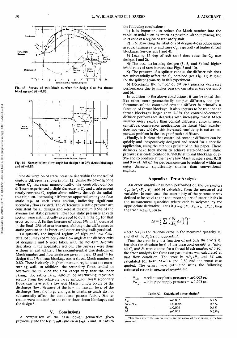
5 6 7 8Circumferential Position, Degrees
Fig. 13 Survey of exit Mach number for design 6 at 3% throatblockage and A/= 0.80.
0 1 2 3 4 5 6 7 8 9 1 0 1 1
6 Circumferential Position, Degrees
Fig. 14 Survey of exit flow angle for design 6 at 3% throat blockageand A/= 0.80.
The distribution of static pressure rise within the controlledcontour diff users is shown in Fig. 12. Unlike the 61/2-deg conewhere Cp increases monotonically, the controlled-contourdiffusers experienced a slight decrease in Cp and a subsequentnearly constant Cp region about midway through the radial-to-axial turn. Increasing differences appeared among the fourstatic taps at each cross section, indicating significantsecondary flows existed. The differences in static pressure areconsistent for all designs and were at maximum 0.5% of theaverage exit static pressure. The four static pressures at eachsection were arithmetically averaged to obtain the Cp for thatcross section. A further increase of about 3% in Cp occurredin the final 13% of area increase, although the differences instatic pressure on the inner- and outer-turning walls persisted.
To quantify the implied regions of high and low flow,detailed surveys of velocity and flow angle at the diffuser exitsof designs 5 and 6 were taken with the hot-film X-probedescribed in the apparatus section. The surveys were donewithout an exit splitter. The circumferential distributions ofMach number and flow angle are given in Figs. 13 and 14 fordesign 6 at 3 % throat blockage and a throat Mach number of0.80. There is clearly a high momentum region near the outer-turning wall. In addition, the secondary flows tended tooverturn the bulk of the flow except very near the innercasing. The rather large amount of overturning measuredresults from the relatively large influence small secondaryflows can have at the low exit Mach number levels of thedischarge flow. Because of the low momentum level of thedischarge flow, the large changes in discharge angle do notsubstantially affect the combustor pattern factor. Similarresults were obtained for the other three throat blockages andfor design 5.
V. ConclusionsA comparison of the basic design geometries given
previously and the test results shown in Figs. 7 and 10 leads to
the following conclusions:1) It is important to reduce the Mach number into the
radial-to-axial turn as much as possible without placing theinlet cone in a region of transitory stall.
2) The deswirling distributions of designs 4-6 produce moregradual turning rates and raise Cp, especially at higher throatblockages (see designs 1 and 4).
3) Leaving 15 deg of exit swirl does raise the Cp (seedesigns 1 and 2).
4) The best performing designs (3, 5, and 6) had higherinitial rates of area increase (see Figs. 3 and 10).
5) The pressure of a splitter vane at the diffuser exit doesnot substantially affect the Cp obtained (see Fig. 11) at leastfor the splitter geometry in this experiment.
6) Decreasing the number of diffuser passages decreasesperformance due to higher passage curvatures (see designs 5and 6).
In addition to the above conclusions, it can be noted thatlike other more geometrically simpler diffusers, the per-formance of the controlled-contour diffuser is primarily afunction of throat blockage. It also appears to be true that atthroat blockages larger than 2-3% the controlled-contourdiffuser performance degrades with increasing throat Machnumber more rapidly than conical diffusers. Since in mostcentrifugal compressor applications the throat Mach numberdoes not vary widely, this increased sensitivity is not an im-portant problem in the design of such a diffuser.
Finally, it is clear that controlled-contour diffusers can bequickly and inexpensively designed and tested for a specificapplication, using the methods presented in this paper. Thesediffusers have been shown to achieve state-of-the-art staticpressure rise coefficients of 0.79-0.82 at throat blockages of 2-3% and to produce at their exits low Mach numbers near 0.10and 0 swirl. All of this performance can be achieved within anouter diameter significantly smaller than conventionalengines.
Appendix: Error AnalysisAn error analysis has been performed on the parameters
Cp, APr/Pr, Bt, and M calculated from the measured testvariables. In each case, the uncertainty of the parameter wasdefined to be equal to the root mean square of uncertainties inthe measurement quantities where each is weighted by theappropriate derivative. Thus if g = g (X],X2,X3,..,Xn), thenthe error in g is given by
where AA", is the random error in the measured quantity Xland all of the Xt 's are independent.
Thus the error in g is a function of not only the errors Xfbut also the absolute level of the measured quantities. Sinceall Cp and Bt were quoted for a throat Mach number of 0.80,the error analysis for these two parameters was calculated atthat flow condition. The error in APT/PT and M wascalculated for both M=0.4 and 0.80 and the worst casequoted. The errors were calculated using the followingestimated errors in measured quantities:
aOn plots where the symbol size is not indicative of these errors, error barsare noted.
Dow
nloa
ded
by U
NIV
ER
SIT
Y O
F Q
UE
EN
SLA
ND
on
June
2, 2
014
| http
://ar
c.ai
aa.o
rg |
DO
I: 1
0.25
14/3
.573
54
JANUARY 1982 COMPACT DIFFUSERS 51
Ps = throat static pressure = ±0.02 psi for plasterinlet, = ±0.01 psi for metal inlet
W = airflow rate = ±0.001 ppsTT = inlet supply temperature = ± 1.60° FA = throat area= ±0.001 in.
These estimated errors reflect instrumentation quality as wellas the accuracy of the measuring equipment itself. Theseerrors resulted in the following calculated uncertainties foundin Table Al.
References!Russo, C.J. and Blair, L.W., "Effect of Size and Reynolds'
Number on Centrifugal Diffuser Performance," ASME Paper 81-GT-8, March 1981.
2Katsanis, T., "Use of Arbitrary Quasi-Orthogonals forCalculating Flow Distribution in the Meridional Plane of a Tur-bomachine," NASA TN D-2546, Dec. 1964.
3Dolan, F.X. and Runstadler, P.W., "Pressure Recovery Per-formance of Conical Diffusers at High Subsonic Mach Numbers,"NASACR-2299, Aug. 1973.
AIAA Meetings of Interest to Journal Readers*Meeting
Date (Issue of AIAA Bulletin in which program will appear)