12
Compact Electrical Random Orbital Sander 150 mm (6 in.) & 125 mm (5 in.)

PB
Compact ElectricalRandom Orbital Sander150 mm (6 in.) & 125 mm (5 in.)
2
7
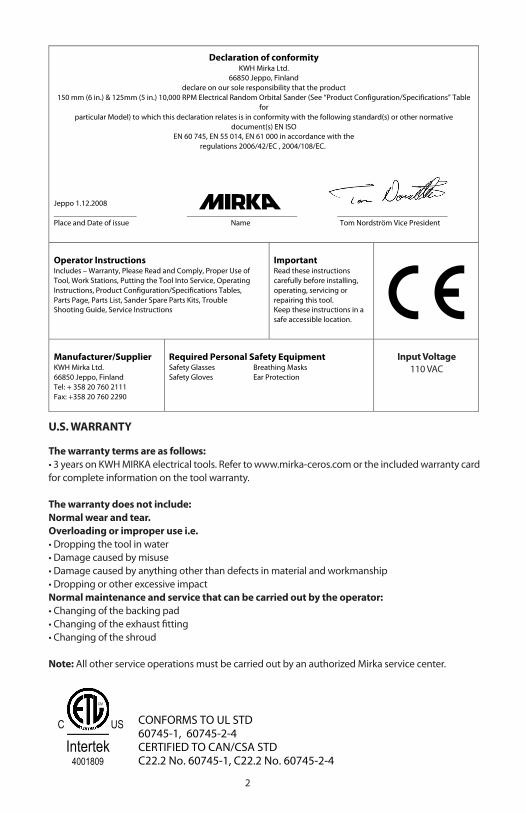
Declaration of conformityKWH Mirka Ltd.
66850 Jeppo, Finlanddeclare on our sole responsibility that the product
150 mm (6 in.) & 125mm (5 in.) 10,000 RPM Electrical Random Orbital Sander (See “Product Configuration/Specifications” Tablefor
particular Model) to which this declaration relates is in conformity with the following standard(s) or other normativedocument(s) EN ISO
EN 60 745, EN 55 014, EN 61 000 in accordance with the regulations 2006/42/EC , 2004/108/EC.
Jeppo 1.12.2008
_____________________ ____________________________ ____________________________Place and Date of issue Name Tom Nordström Vice President
Operator InstructionsIncludes – Warranty, Please Read and Comply, Proper Use ofTool, Work Stations, Putting the Tool Into Service, OperatingInstructions, Product Configuration/Specifications Tables,Parts Page, Parts List, Sander Spare Parts Kits, TroubleShooting Guide, Service Instructions
ImportantRead these instructionscarefully before installing,operating, servicing orrepairing this tool.Keep these instructions in asafe accessible location.
Manufacturer/SupplierKWH Mirka Ltd.66850 Jeppo, FinlandTel: + 358 20 760 2111Fax: +358 20 760 2290
Required Personal Safety EquipmentSafety Glasses Breathing MasksSafety Gloves Ear Protection
Input Voltage90-240 VAC
WarrantyThe warranty terms are as follows:- 12 months on KWH MIRKA electrical tools.The warranty period commences at the date of purchase. The warranty only covers imputable material and manufacturingdefects.Parts replacement or repair during the warranty period is free of charge if carried out by an official KWH MIRKA service center.Freight costs are always to be paid by the purchaser.The warranty does not include:Normal wear and tear i.e.
- Bearings, backing pad, shroud- Industrial continuous usage
Overloading or improper use i.e.- Dropping the tool in water- Damage caused by misuse- Damage caused by anything other than defects in material and workmanship- Dropping or other excessive impact
Normal maintenance and service that can be carried out by the operator :- Changing of the packing pad- Changing of the spindle bearing- Changing of the exhaust fitting- Changing of the shroud
NB! All other service operations must be carried out by an authorized Mirka service center.The warranty only covers the local repair, not the tool replacement.Compensation for downtime and loss of production are explicitly not included in the warranty.
U.S. WARRANTY
The warranty terms are as follows:• 3 years on KWH MIRKA electrical tools. Refer to www.mirka-ceros.com or the included warranty card for complete information on the tool warranty.
The warranty does not include:Normal wear and tear.Overloading or improper use i.e.• Dropping the tool in water• Damage caused by misuse• Damage caused by anything other than defects in material and workmanship• Dropping or other excessive impactNormal maintenance and service that can be carried out by the operator:• Changing of the backing pad• Changing of the exhaust fitting• Changing of the shroud
Note: All other service operations must be carried out by an authorized Mirka service center.
CONFORMS TO UL STD 60745-1, 60745-2-4CERTIFIED TO CAN/CSA STDC22.2 No. 60745-1, C22.2 No. 60745-2-4
Intertek4001809
C US
CM
Input Voltage110 VAC

2 3
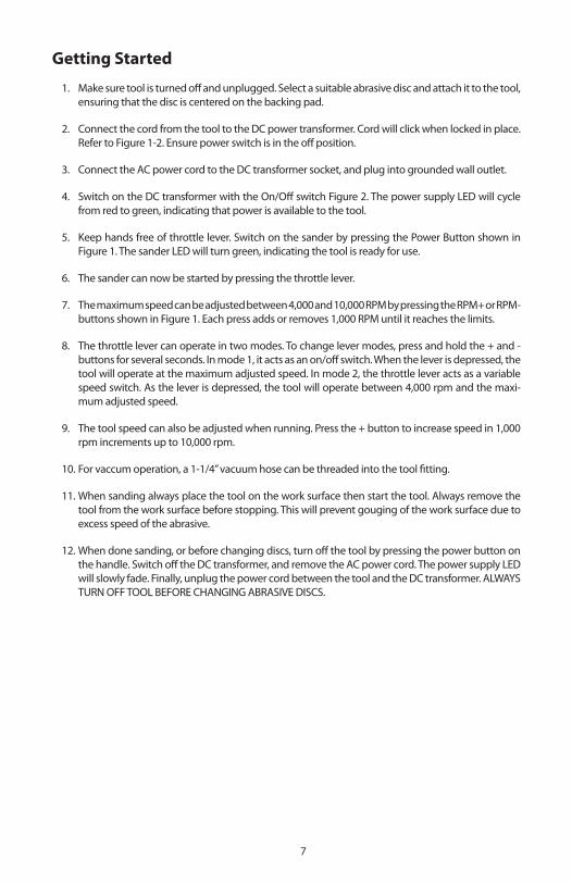
FIGURE 1. Sander
FIGURE 2. DC Power transformer unit
On/Off Switch
AC socket
AC Power Cord
LED
DC socket
4
General Power Tool Safety Warnings
WARNING Read all safety warnings and all instructions. Failure to follow the warnings and instructions may result in electric shock, fire and/or serious injury. Save all warnings and instructions for future reference. The term “power tool” in the warnings refers to any power supplied (corded) power tool or battery-operated (cordless) power tool.
1) Work area safety a) Keep work area clean and well lit. Cluttered or dark areas invite accidents. b) Do not operate power tools in explosive atmospheres, such as in the presence of flammable liquids, gases or dust. Power tools create sparks which may ignite the dust or fumes. c) Keep children and bystanders away while operating a power tool. Distractions can cause you to lose control.
2) Electrical safety a) Power tool plugs must match the outlet. Never modify the plug in any way. Do not use any adapter plugs with grounded (earthed) power tools. Unmodified plugs and matching outlets will reduce risk of electric shock. b) Avoid body contact with earthed or grounded surfaces, such as pipes, radiators, ranges and refrigerators. There is an increased risk of electric shock if your body is earthed or grounded. c) Do not expose power tools to rain or wet conditions. Water entering a power tool will in-crease the risk of electric shock. d) Do not abuse the cord. Never use the cord for carrying, pulling or unplugging the power tool. Keep cord away from heat, oil, sharp edges and moving parts. Damaged or entangled cords increase the risk of electric shock. e) When operating a power tool outdoors, use an extension cord suitable for outdoor use. Use of a cord suitable for outdoor use reduces the risk of electric shock. f ) If operating a power tool in a damp location is unavoidable, use a ground fault circuit interrupter (GFCI) protected supply. Use of a GFCI reduces the risk of electric shock.
3) Personal safety a) Stay alert, watch what you are doing and use common sense when operating a power tool. Do not use a power tool while you are tired or under the influence of drugs, alcohol or medication. A moment of inattention while operating power tools may result in serious personal injury. b) Use personal protective equipment. Always wear eye protection. Protective equipment such as dust mask, non-skid safety shoes, hard hat, or hearing protection used for appropriate conditions will reduce personal injuries. c) Prevent unintentional starting. Ensure the switch is in the off-position before connecting to power source and/or battery pack, picking up or carrying the tool. Carrying power tools with your finger on the switch or energising power tools that have the switch on invites accidents. d) Remove any adjusting key or wrench before turning the power tool on. A wrench or a key left attached to a rotating part of the power tool may result in personal injury. e) Do not overreach. Keep proper footing and balance at all times. This enables better control of the power tool in unexpected situations. f ) Dress properly. Do not wear loose clothing or jewellery. Keep your hair, clothing and gloves away from moving parts. Loose clothes, jewellery or long hair can be caught in moving parts. g) If devices are provided for the connection of dust extraction and collection facilities, en-sure these are connected and properly used. Use of dust collection can reduce dust related hazards.

4 5
4) Power tool use and care a) Do not force the power tool. Use the correct power tool for your application. The correct power tool will do the job better and safer at the rate for which it was designed. b) Do not use the power tool if the switch does not turn it on and off. Any power tool that can-not be controlled with the switch is dangerous and must be repaired. c) Disconnect the plug from the power source before making any adjustments, changing ac-cessories, or storing power tools. Such preventive safety measures reduce the risk of starting the power tool accidentally.d) Store idle power tools out of the reach of children and do not allow persons unfamiliar with the power tool or these instructions to operate the power tool. Power tools are dangerous in the hands of untrained users. e) Maintain power tools. Check for misalignment or binding of moving parts, breakage of parts and any other condition that may affect the power tool’s operation. If damaged, have the power tool repaired before use. Many accidents are caused by poorly maintained power tools. g) Use the power tool in accordance with these instructions, taking into account the working conditions and the work to be performed. Use of the power tool for operations different from those intended could result in a hazardous situation.
5) Service a) Have your power tool serviced by an authorized Mirka service center using only identical replacement parts. This will ensure that the safety of the power tool is maintained.
Additional Safety Warnings
a) Always ensure that the material to be sanded is firmly fixed to prevent its movement.b) Dust can be highly combustible. Vacuum dust collection bag should be cleaned or re-placed daily. Cleaning or replacing of bag also assures optimum performance.c) Keep hands clear of the spinning pad during use.d) Do not allow the tool to free speed without taking precautions to protect any persons or objects from the loss of the abrasive or pad.

6
Proper Use of Tool
This sander is designed for sanding a variety of materials i.e. wood, composites, plastics, etc. using abrasive discs designed for this purpose. Do not use this sander for any other purpose than that specified without consulting the manufacturer or the manufacturer’s authorized supplier. Do not press on the shroud when sanding. Pressing on the shroud will reduce its lifespan. Do not use back-ing pads that have a working speed less than 10,000 RPM free speed. The cooling air vents on the housing must always be free of blockages and clean to ensure air circulation. Any maintenance or repair work requiring the motor housing to be opened may only be carried out by an authorized service center.
Work Stations
The tool is intended to be operated as a hand held tool. It is always recommended that the tool should be used when standing on a solid floor. It can be in any position but before any such use, the operator must be in a secure position having a firm grip and footing and be aware that the sander can develop a torque reaction.
Disposal Information
Danger! Disposal information for the old appliance! Render redundant power tools unusable by removing the power cord. Only for EU countries. Do not dispose of electric tools together with household waste material! In observance of European Directive 2002/95/CE, 2002/96/EC + 2003/108/CE on waste electrical and electronic equipment and its implementation in accordance with national law, electric tools that have reached the end of their life must be collected separately and returned to an environmentally compatible recycling facility.
6 7
Getting Started
1. Make sure tool is turned off and unplugged. Select a suitable abrasive disc and attach it to the tool, ensuring that the disc is centered on the backing pad.
2. Connect the cord from the tool to the DC power transformer. Cord will click when locked in place. Refer to Figure 1-2. Ensure power switch is in the off position.
3. Connect the AC power cord to the DC transformer socket, and plug into grounded wall outlet.
4. Switch on the DC transformer with the On/Off switch Figure 2. The power supply LED will cycle from red to green, indicating that power is available to the tool.
5. Keep hands free of throttle lever. Switch on the sander by pressing the Power Button shown in Figure 1. The sander LED will turn green, indicating the tool is ready for use.
6. The sander can now be started by pressing the throttle lever.
7. The maximum speed can be adjusted between 4,000 and 10,000 RPM by pressing the RPM+ or RPM- buttons shown in Figure 1. Each press adds or removes 1,000 RPM until it reaches the limits.
8. The throttle lever can operate in two modes. To change lever modes, press and hold the + and - buttons for several seconds. In mode 1, it acts as an on/off switch. When the lever is depressed, the tool will operate at the maximum adjusted speed. In mode 2, the throttle lever acts as a variable speed switch. As the lever is depressed, the tool will operate between 4,000 rpm and the maxi-mum adjusted speed.
9. The tool speed can also be adjusted when running. Press the + button to increase speed in 1,000 rpm increments up to 10,000 rpm.
10. For vaccum operation, a 1-1/4” vacuum hose can be threaded into the tool fitting.
11. When sanding always place the tool on the work surface then start the tool. Always remove the tool from the work surface before stopping. This will prevent gouging of the work surface due to excess speed of the abrasive.
12. When done sanding, or before changing discs, turn off the tool by pressing the power button on the handle. Switch off the DC transformer, and remove the AC power cord. The power supply LED will slowly fade. Finally, unplug the power cord between the tool and the DC transformer. ALWAYS TURN OFF TOOL BEFORE CHANGING ABRASIVE DISCS.

8
1
2
3
4
5
6
7
8
9
10
12
13
14
15
11
16
17
18
19
20
21
22
2423
25
26
27
A
Parts Schematic
8 9
Parts List
ITEM DESCRIPTION QTY. Part Number
n/s DC Power Supply (Transformer) 1 MIN6522511
n/s Power cable US 110V 1 MIN5617511
1 Motor assembly 150mm/5mm 1 MIN6510111
Motor assembly 125mm/5mm 1 MIN5510111
2 Fan 150mm/5mm 1 MIN6510211
Fan 125mm/5mm 1 MIN5510211
3 Double row bearing 1 8993019711 (Bearing Kit)
4 Spacer 1 8993019711 (Bearing Kit)
5 Washer 1 8993019711 (Bearing Kit)
6 Retaining ring 1 8993019711 (Bearing Kit)
7 Spindle 1 8993011611
8 24mm Pad Wrench 1 8993008011
9 Backing Pad (150mm) 1 916GV15
Backing Pad (125mm) 1 915GV20
10 Lever 1 MIN6521011 (Lever Kit)
11 Pin 1 inc. w/MIN6521011
12 Grip 1 MIN6511211
13 Start button 1 MIN6521311 (Start Button Kit)
14 Start button spring 1 MIN6521311 (Start Button Kit)
15 Cover plate 1 MIN6511511
16 PCB screw 4 MIN6522311 (Screw Kit)
17 Speed controller 1 MIN6511711
18 Housing 1 MIN6511811
19 Shroud 150mm 1 MIN6511911
Shroud 125mm 1 MIN6515911
20 Membrane keyboard 1 MIN6512011
21 Cable support 1 inc. w/MIN6522211
22 DC cable 4m 1 MIN6522211
23 Housing screw 6 MIN6522311 (Screw Kit)
24 DC connector 1 MIN6512411
25 28mm swivel exhaust assembly 1 MIN6519011 (Assembly)
26 Washer 1 inc. w/MIN6519011
27 Exhaust pipe screw 1 inc. w/MIN6519011
n/s Systainer 1 MIN6530011
(n/s = not shown)
10
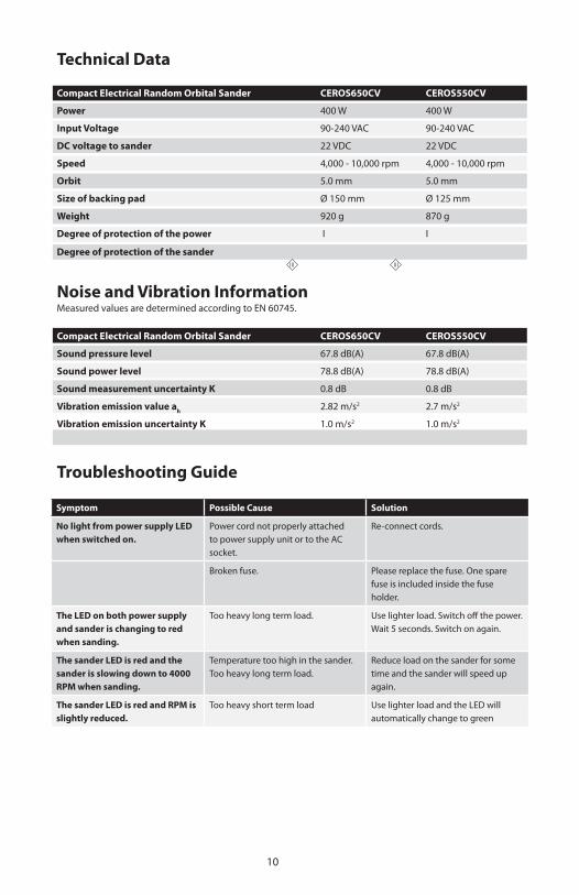
Technical Data
Compact Electrical Random Orbital Sander CEROS650CV CEROS550CV
Power 400 W 400 W
Input Voltage 90-240 VAC 90-240 VAC
DC voltage to sander 22 VDC 22 VDC
Speed 4,000 - 10,000 rpm 4,000 - 10,000 rpm
Orbit 5.0 mm 5.0 mm
Size of backing pad Ø 150 mm Ø 125 mm
Weight 920 g 870 g
Degree of protection of the power I I
Degree of protection of the sander
Noise and Vibration InformationMeasured values are determined according to EN 60745.
Compact Electrical Random Orbital Sander CEROS650CV CEROS550CVV
Sound pressure level 67.8 dB(A) 67.8 dB(A)
Sound power level 78.8 dB(A) 78.8 dB(A)
Sound measurement uncertainty K 0.8 dB 0.8 dB
Vibration emission value ah 2.82 m/s2 2.7 m/s2
Vibration emission uncertainty K 1.0 m/s2 1.0 m/s2
Troubleshooting Guide
Symptom Possible Cause Solution
No light from power supply LED when switched on.
Power cord not properly attached to power supply unit or to the AC socket.
Re-connect cords.
Broken fuse. Please replace the fuse. One spare fuse is included inside the fuse holder.
The LED on both power supply and sander is changing to red when sanding.
Too heavy long term load. Use lighter load. Switch off the power. Wait 5 seconds. Switch on again.
The sander LED is red and the sander is slowing down to 4000 RPM when sanding.
Temperature too high in the sander. Too heavy long term load.
Reduce load on the sander for some time and the sander will speed up again.
The sander LED is red and RPM is slightly reduced.
Too heavy short term load Use lighter load and the LED will automatically change to green

10 11
Notes:

KWH Mirka LtdFinland
Mirka Abrasives Inc. Twinsburg, OH 44140 USATel. 330.963.6421www.mirka-usa.com
Quality from start to finish
LI-U
MC
1011
202
• re
v. 1
2/20
10


