32
Operating Instructions BG 805 155 BE / B (2005-08) 1 Compact FullRange™ Gauge FPM sealed PKR 251
Operating Instructions
BG 805 155 BE / B (2005-08) 1
CompactFullRange™ GaugeFPM sealed
PKR 251

2 BG 805 155 BE / B (2005-08) PKR 251
Table of Contents
Product Identification 3Validity 3Intended Use 3Functional Principle 3
1 Safety 41.1 Symbols Used 41.2 Personnel Qualifications 41.3 Safety Information 41.4 Liability and Warranty 4
2 Technical Data 5
3 Installation 83.1 Installation 83.1.1 Removing the Magnet Unit (Only for Gauges With CF Flanges) 93.2 Electrical Connection 93.2.1 Use With a Pfeiffer Vacuum Measurement Unit 93.2.2 Use With Another Evaluation Unit 10
4 Operation 124.1 Measurement Principle, Measuring Behavior 12
5 Maintenance 145.1 Adjusting the Gauge 145.2 Cleaning the Gauge / Replacing Parts 155.2.1 Disassembling the Gauge 165.2.2 Cleaning the Gauge 175.2.3 Reassembling the Gauge 185.3 What to Do in Case of Problems 19
6 Removing the Gauge From the Vacuum System 20
7 Returning the Product 21
8 Accessories 21
9 Spare Parts 22
10 Disposal 23
Appendix 24A: Measuring Signal vs. Pressure 24B: Gas Type Dependence 26
Declaration of Contamination 28
For cross references within this document, the symbol (→ XY) is used, forreferences to other documents, the symbol (→ [Z]).

BG 805 155 BE / B (2005-08) PKR 251 3
In all communications with Pfeiffer Vacuum, please specify the information given onthe product nameplate.
Com
pact
Ful
lRan
geTM
Gau
geVACU
UM
Pfeiffer Vacuum, D - 35614 AsslarTyp:No:F-No: V ; W
This document applies to products with part numberPTR26000 (DN 25 ISO-KF flange)PTR26001 (DN 40 ISO-KF flange)PTR26002 (DN 40 CF-F flange)
The part number can be taken from the product nameplate.
We reserve the right to make technical changes without prior notice.
The PKR 251 Compact FullRange™ Gauge has been designed for vacuummeasurement in the pressure range of 5×10⁻⁹ … 1000 mbar.
The PKR 251 can be used with a Pfeiffer Vacuum measurement unit for CompactGauges or with another evaluation unit.
Over the whole measurement range, the measuring signal is output as a logarithmof the pressure.
The PKR 251 gauge consists of two separate measurement systems (the Piraniand the cold cathode system according to the inverted magnetron principle). Theyare combined in such a way that for the user, they behave as one single measure-ment system.
Product Identification
Validity
Intended Use
Functional Principle

4 BG 805 155 BE / B (2005-08) PKR 251
1 Safety
DANGER
Information on preventing any kind of physical injury.
WARNING
Information on preventing extensive equipment and environmental damage.
Caution
Information on correct handling or use. Disregard can lead to malfunctions orminor equipment damage.
Skilled personnel
All work described in this document may only be carried out by persons whohave suitable technical training and the necessary experience or who have beeninstructed by the custodian of the product.
• Adhere to the applicable regulations and take the necessary precautions for theprocess media used.Consider possible reactions between the materials (→ 7) and the processmedia.Consider possible reactions of the process media due to the heat generated bythe product.
• Adhere to the applicable regulations and take the necessary precautions for allwork you are going to do and consider the safety information in this document.
• Before you begin to work, find out whether any vacuum components are con-taminated. Adhere to the relevant regulations and take the necessary pre-cautions when handling contaminated parts.
Pass on the safety information to other users.
Pfeiffer Vacuum assumes no liability and the warranty becomes null and void if thecustodian or third parties• disregard the information in this document• use the product in a non-conforming manner• make any kind of changes (modifications, alterations etc.) to the product• use the product with accessories not listed in the corresponding product
documentation.
The custodian assumes the responsibility in conjunction with the process mediaused.
1.1 Symbols Used
1.2 Personnel Qualifications
1.3 Safety Information
1.4 Liability and Warranty

BG 805 155 BE / B (2005-08) PKR 251 5
2 Technical Data
Admissible temperaturesStorageOperationBakeout
-40 °C … +65 °C+ 5 °C … +55 °C+150 °C (without electronics unit andmagnetic shielding)
Relative humidity max. 80% at temperatures ≤+31 °Cdecreasing to 50% at +40 °C
Use indoors onlyaltitude up to 2000 m (6600 ft)
Measurement range (air, N2) 5×10⁻⁹ … 1000 mbarAccuracy ≈±30%
in the range 1×10⁻⁸ … 100 mbarReproducibility ≈±5%
in the range 1×10⁻⁸ … 100 mbarGas type dependence → Appendix B
Adjustment (→ 14)Pirani measurement circuit
<HV> trimmer potentiometer at <1×10⁻⁴ mbar(while depressing the pin)
<ATM> trimmer potentiometer at atmospheric pressureCold cathode measurement circuit no adjustment (the gauge is adjusted at
the factory and requires no main-tenance)
Type of protection IP 40Maximum pressure (absolute) 10 bar
only for inert gases <55 °C
Supply
DANGER
The gauge may only be connected to supply or measurement unitsthat conform to the requirements of a grounded protective extra-lowvoltage (SELV-E according to EN 61010). The connection to thegauge has to be fused.1)
Voltage at the gauge 15.0 … 30.0 VDC (max. ripple 1 Vpp)Power consumption ≤2 WFuse1) ≤1 AT
The minimum voltage of the power supply must be increased proportionally to thelength of the measuring cable.
Voltage at the supply unit withmaximum cable length 16.0 … 30.0 VDC (max. ripple 1 Vpp)
Electrical connection Hirschmann compact connectortype GO 6, 6 pins, male
Cable 5 poles plus screeningMaximum cable length 75 m (0.25 mm² conductor)
100 m (0.34 mm² conductor)300 m (1.0 mm² conductor)
1) Pfeiffer Vacuum measurement and control units for Compact Gauges fulfill
these requirements.

6 BG 805 155 BE / B (2005-08) PKR 251
Operating voltage(in the measuring chamber) ≤3.3 kVOperating current(in the measuring chamber) ≤500 µA
Output signal (measuring signal)Voltage range ≈0 V … ≈+10.5 VRelationship voltage-pressure logarithmic, increase 0.6 V / decade
(→ Appendix A)Error signals <0.5 V (no supply)
>9.5 V (Pirani measurement elementdefective; filament rupture)
Output impedance 2×10 ΩMinimum load 10 kΩ, short-circuit proofResponse time pressure dependent
p > 10-6 mbarp = 10-8 mbar
≈10 ms≈1 s
Gauge identification → Figure 1Pirani-only mode 11.1 kΩ resistor referenced to supply
commonCombined Pirani / cold cathodemode
9.1 kΩ resistor referenced to supplycommon
The following conditions must befulfilled:
Polarity The polarity of pin 1 referenced tosupply common is always positive.
Measurementwith constant current
with constant voltage
measurement current within range0.2 … 0.3 mAmeasurement voltage within range2 … 3 V
Grounding concept → Figure 1Vacuum flange-measurementcommon
connected via 10 kΩ(max. voltage differentialwith respect to safety ±50 Vwith respect to accuracy ±10 V)
Supply common-signal common conducted separately; differentialmeasurement recommended for cablelengths ≥6 m
BG 805 155 BE / B (2005-08) PKR 251 7
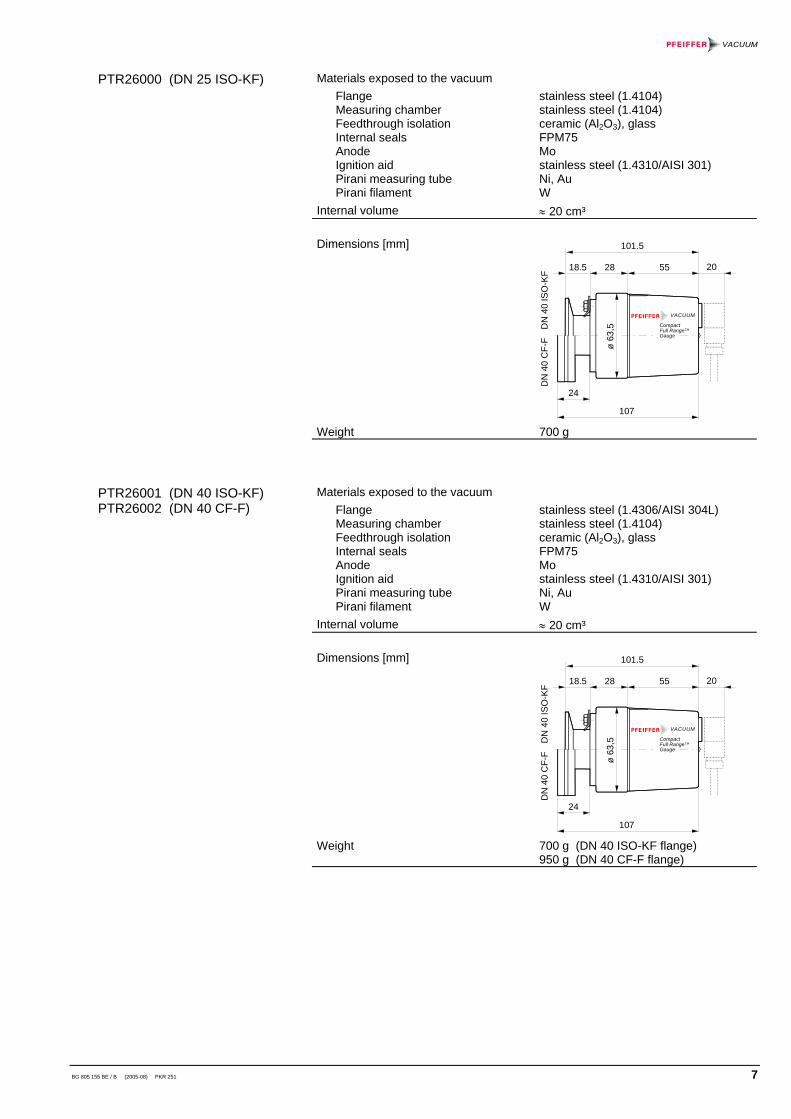
Materials exposed to the vacuumFlangeMeasuring chamberFeedthrough isolationInternal sealsAnodeIgnition aidPirani measuring tubePirani filament
stainless steel (1.4104)stainless steel (1.4104)ceramic (Al2O3), glassFPM75Mostainless steel (1.4310/AISI 301)Ni, AuW
Internal volume ≈ 20 cm³
Dimensions [mm]
CompactFull RangeTM
Gauge
VACUUM
107
101.5
18.5
24
ø 63
,5
28 55
DN
40
CF-
FD
N 4
0 IS
O-K
F
20
Weight 700 g
Materials exposed to the vacuumFlangeMeasuring chamberFeedthrough isolationInternal sealsAnodeIgnition aidPirani measuring tubePirani filament
stainless steel (1.4306/AISI 304L)stainless steel (1.4104)ceramic (Al2O3), glassFPM75Mostainless steel (1.4310/AISI 301)Ni, AuW
Internal volume ≈ 20 cm³
Dimensions [mm]
CompactFull RangeTM
Gauge
VACUUM
107
101.5
18.5
24
ø 63
,5
28 55
DN
40
CF-
FD
N 4
0 IS
O-K
F
20
Weight 700 g (DN 40 ISO-KF flange)950 g (DN 40 CF-F flange)
PTR26000 (DN 25 ISO-KF)
PTR26001 (DN 40 ISO-KF)PTR26002 (DN 40 CF-F)
8 BG 805 155 BE / B (2005-08) PKR 251
3 Installation
Caution
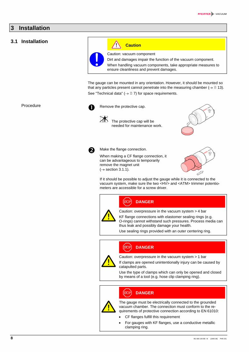
Caution: vacuum componentDirt and damages impair the function of the vacuum component.When handling vacuum components, take appropriate measures toensure cleanliness and prevent damages.
The gauge can be mounted in any orientation. However, it should be mounted sothat any particles present cannot penetrate into the measuring chamber (→ 13).See "Technical data" (→ 7) for space requirements.
Remove the protective cap.
The protective cap will beneeded for maintenance work.
Make the flange connection.
When making a CF flange connection, itcan be advantageous to temporarilyremove the magnet unit(→ section 3.1.1).
If it should be possible to adjust the gauge while it is connected to thevacuum system, make sure the two <HV> and <ATM> trimmer potentio-meters are accessible for a screw driver.
DANGER
Caution: overpressure in the vacuum system > 4 barKF flange connections with elastomer sealing rings (e.g.O-rings) cannot withstand such pressures. Process media canthus leak and possibly damage your health.Use sealing rings provided with an outer centering ring.
DANGER
Caution: overpressure in the vacuum system > 1 barIf clamps are opened unintentionally injury can be caused bycatapulted parts.Use the type of clamps which can only be opened and closedby means of a tool (e.g. hose clip clamping ring).
DANGER
The gauge must be electrically connected to the groundedvacuum chamber. The connection must conform to the re-quirements of protective connection according to EN 61010:• CF flanges fulfill this requirement• For gauges with KF flanges, use a conductive metallic
clamping ring.
3.1 Installation
Procedure
BG 805 155 BE / B (2005-08) PKR 251 9
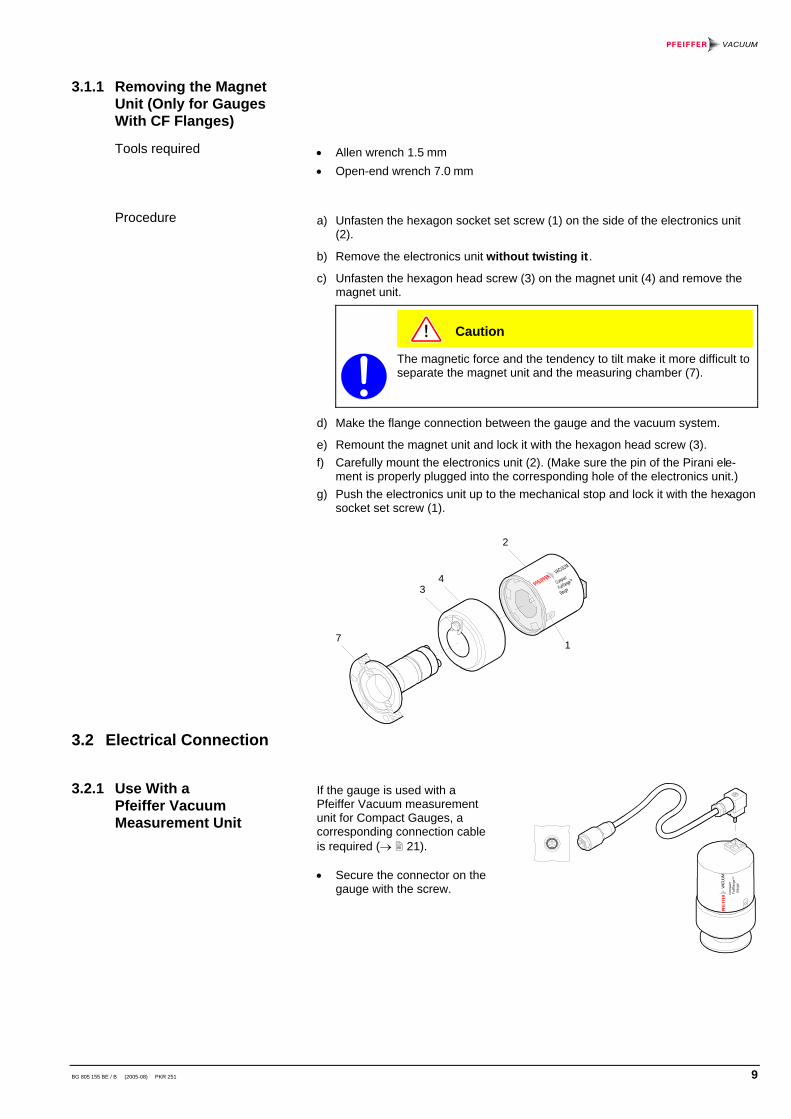
• Allen wrench 1.5 mm• Open-end wrench 7.0 mm
a) Unfasten the hexagon socket set screw (1) on the side of the electronics unit(2).
b) Remove the electronics unit without twisting it.
c) Unfasten the hexagon head screw (3) on the magnet unit (4) and remove themagnet unit.
Caution
The magnetic force and the tendency to tilt make it more difficult toseparate the magnet unit and the measuring chamber (7).
d) Make the flange connection between the gauge and the vacuum system.
e) Remount the magnet unit and lock it with the hexagon head screw (3).f) Carefully mount the electronics unit (2). (Make sure the pin of the Pirani ele-
ment is properly plugged into the corresponding hole of the electronics unit.)g) Push the electronics unit up to the mechanical stop and lock it with the hexagon
socket set screw (1).
1
2
34
7
If the gauge is used with aPfeiffer Vacuum measurementunit for Compact Gauges, acorresponding connection cableis required (→ 21).
• Secure the connector on thegauge with the screw. C
ompa
ct F
ullR
ange
TM
Gau
geVACU
UM
3.1.1 Removing the MagnetUnit (Only for GaugesWith CF Flanges)
Tools required
Procedure
3.2 Electrical Connection
3.2.1 Use With aPfeiffer VacuumMeasurement Unit

10 BG 805 155 BE / B (2005-08) PKR 251
The gauge can also be operated with other evaluation units. In this case, anindividual connection cable must be made.For cable lengths up to 6 m (with a conductor cross-section of 0.34 mm2), themeasuring signal can be read directly between the positive signal output (pin 2) andthe supply common (pin 5) without the degree of accuracy being lowered. Forlonger measurement cable lengths, we recommend a differential measurementbetween the signal output and the signal common (pin 3) (as a result of the voltagedrop along the supply cable ground lead, the common mode signal is approx. 1.0 Vat the maximum admissible cable length).
Prepare the connector (orderingnumber → 21).
Solder the connection cable according to the diagram.
10
10
Ident
2
3
1
4
5
6
V –+
–+
10k
Figure 1: Electrical connection
Pin 1 identificationPin 2 signal output
(measuring signal)Pin 3 signal commonPin 4 supplyPin 5 supply commonPin 6 screen
2
5
31
64
Connector, soldering side
WARNING
The supply common (pin 5) and the screen (pin 6) must beconnected to the supply unit with protective ground.Incorrect connection, incorrect polarity, or inadmissible supplyvoltages can damage the gauge.
Reassemble the connector.
3.2.2 Use With AnotherEvaluation Unit
Procedure

BG 805 155 BE / B (2005-08) PKR 251 11
Plug in the connector.
Secure the connector on thegauge with the screw.
Com
pact
Ful
lRan
geTM
Gau
geVACU
UM

12 BG 805 155 BE / B (2005-08) PKR 251
4 Operation
As soon as the required voltage is applied, the measuring signal is availablebetween pins 2 and 3. (→ Appendix A for the relationship between the measuringsignal and the pressure).
Allow for a stabilizing time of approx. 10 min. Once the gauge has been switchedon, permanently leave it on irrespective of the pressure.
The PKR 251 consists of tow separate measurement systems (Pirani and coldcathode system according to the inverted magnetron principle). They are combinedin such a way that for the user, they behave as one single measurement system.
The optimum measurement configuration for the particular pressure range, in whichmeasurement is performed, is used:
10-4 mbar
10-2 mbar
1000 mbar
5 × 10⁻⁹ mbar
Cold cathode Pirani
• The Pirani measurement circuit is always on.• The cold cathode measurement circuit is controlled by the Pirani circuit and is
activated only at pressures <1×10⁻² mbar.
The identification output (pin 1) indicates the current status of the gauge:
Pressure Green lamp onthe gauge
Operating mode Identification
p > 1×10⁻² mbar Pirani-only mode 11.1 kΩ (Pirani)
p < 1×10⁻² mbar
Pirani-only mode (coldcathode measurementcircuit not ignited)
11.1 kΩ (Pirani)
Combined operation 9.1 kΩ (combined)
As long as the cold cathode measurement circuit has not ignited, the measurementvalue of the Pirani is output as measuring signal (if p < 5×10⁻⁴ mbar, "Piraniunderrange" is displayed).
The measuring signal depends on the type of gas being measured. The curves areaccurate for N2, O2, dry air and CO. They can be mathematically converted forother gases (→ Appendix B).
If you are using a Pfeiffer Vacuum measurement unit for Compact Gauges, you canenter a calibration factor to correct the measurement value displayed (→ of thatmeasurement unit).
When cold cathode measurement systems are activated, an ignition delay occurs.The delay time increases at low pressures and is typically:
10-5 mbar ≈ 1 second 10-7 mbar ≈ 20 seconds5×10-9 mbar ≈ 2 minutes
As long as the cold cathode measurement circuit has not yet ignited, the measure-ment value of the Pirani is output as measuring signal ("Pirani underrange" isdisplayed for pressures <5×10⁻⁴ mbar). The identification output (pin 1) indicatesthe Pirani-only mode.
4.1 Measurement Principle,Measuring Behavior
Gas type dependence
Ignition delay

BG 805 155 BE / B (2005-08) PKR 251 13
Caution
If the gauge is activated at a pressure p < 3×10⁻⁹, the gauge cannotrecognize whether the cold cathode system has ignited. It indicates"Pirani-Underrange".
Caution
Once flanged on, permanently leave the PKR 251 gauge in theoperating mode irrespective of the pressure range. Like this, theignition delay of the cold cathode measurement circuit is alwaysnegligible (<1 s), and thermal stabilizing effects are minimized.
Caution
Gauge failures due to contamination are not covered by the warranty.
Gauge contamination is influenced by the process media used as well as anypresent or new contaminants and their respective partial pressures. Continuousoperation in the range of 10-4 mbar ... 10-2 mbar can cause severe contaminationas well as reduced up-time and maintenance cycles. With constantly low pressures(p < 1×10⁻⁶ mbar), the gauge can be operated for more than one year withoutcleaning (cleaning the gauge → 17).
Contamination of the gauge generally causes a deviation of the measured values:• In the high pressure range (1×10⁻³ mbar ... 0.1 mbar), the pressure indication is
too high (contamination of the Pirani element). Readjustment of the Piranimeasurement system → 14.
• In the low pressure range (p < 1×10⁻³ mbar), the pressure indication is usuallytoo low (contamination of the cold cathode system). In case of severe contami-nation, instabilities can occur (layers of the measuring chamber peel off).Contamination due to insulation layers can even lead to a complete failure ofthe discharge ("Underrange" is displayed).
Contamination can to a certain extent be reduced by:• geometric protection measures (e.g. screenings, elbows) for particles that
spread rectilinearly• mounting the flange of the gauge at a place where the partial pressure of the
pollutants is particularly low.
Special precautions are required for vapors deposited under plasma (of the coldcathode measurement system). It may even be necessary to temporarily switch ofthe gauge while vapors occur.
Contamination

14 BG 805 155 BE / B (2005-08) PKR 251
5 Maintenance
DANGER
Caution: contaminated partsContaminated parts can be detrimental to health.Before you begin to work, find out whether any parts are contaminated.Adhere to the relevant regulations and take the necessary precautionswhen handling contaminated parts.
The gauge is factory-calibrated. Readjusting the gauge can become necessary dueto use under different climatic conditions, aging, or contamination (→ 13).
The cold cathode measurement circuit, which is dominant for low pressures(<1×10⁻³ mbar), is factory-calibrated and cannot be adjusted. By way of contrast,the Pirani measurement circuit can be adjusted. Any adjustment has a negligibleeffect on the pressure range between approx. 10-2 mbar and 102 mbar.
• Screw driver No. 0• Cylindrical pin ø ≈ 3 mm
Put the gauge into operation (if possible, in the position, in which it will beused later on).
Evacuate the vacuum system to p << 10-4 mbar, and then wait 10 minutes.
Turn the nameplate counter-clockwise until the mechanical stop is reached.
Com
pact
Ful
lRan
geTM
Gau
geVACU
UM While depressing the pin with the cylindrical pin,adjust the <HV> potentiometer... to 5×10⁻⁴ mbar or ... to 4.2 V.
Then turn thepotentiometer counter-clockwise by .
Vent with air or nitrogen to atmospheric pressure and then wait 10 minutes.
Turn the nameplate clockwise until the mechanical stop is reached.
5.1 Adjusting the Gauge
Tools required
Procedure

BG 805 155 BE / B (2005-08) PKR 251 15
Com
pact
Ful
lRan
geTM
Gau
geVACU
UM
Adjust the <ATM> potentiometer ...
... to 1×10³ mbar or ... to 8.6 V
Turn the nameplate back to its original position (it will catch).
DANGER
Caution: cleaning agentsCleaning agents can be detrimental to health and environment.Adhere to the relevant regulations and take the necessary precautionswhen handling and disposing of cleaning agents.
Caution
We recommend to replace the Pirani element when cleaning thegauge.
• Allen wrench 1.5 mm• Allen wrench 3.0 mm• Open-end wrench 7.0 mm• Pliers for circlip• Polishing cloth (400 grain) or Scotch-Brite• Tweezers• Cleaning alcohol• Mounting tool for ignition aid• Ignition aid• Pirani element (13) incl. FPM seal (13a)• FPM seal (11) for anode feedthrough
5.2 Cleaning the Gauge /Replacing Parts
Tools / material required
16 BG 805 155 BE / B (2005-08) PKR 251
1
2
34
7
65
8a8
9
12
1010a
11
1313a
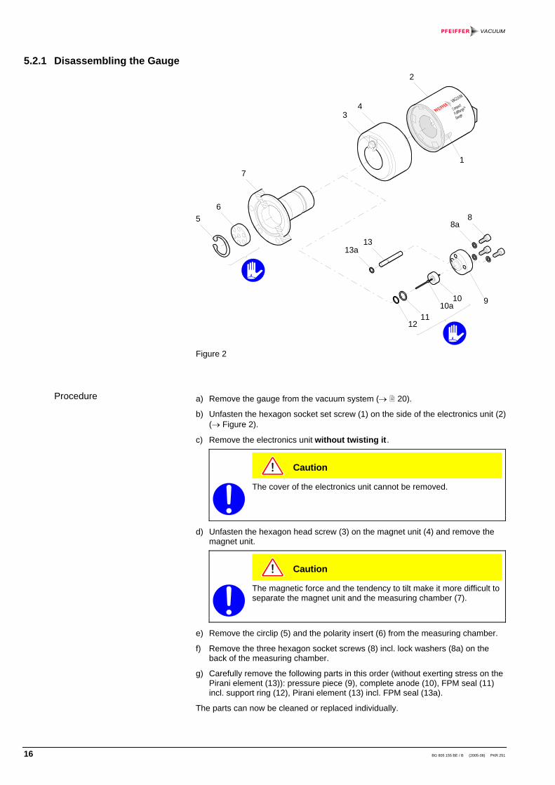
Figure 2
a) Remove the gauge from the vacuum system (→ 20).
b) Unfasten the hexagon socket set screw (1) on the side of the electronics unit (2)(→ Figure 2).
c) Remove the electronics unit without twisting it.
Caution
The cover of the electronics unit cannot be removed.
d) Unfasten the hexagon head screw (3) on the magnet unit (4) and remove themagnet unit.
Caution
The magnetic force and the tendency to tilt make it more difficult toseparate the magnet unit and the measuring chamber (7).
e) Remove the circlip (5) and the polarity insert (6) from the measuring chamber.
f) Remove the three hexagon socket screws (8) incl. lock washers (8a) on theback of the measuring chamber.
g) Carefully remove the following parts in this order (without exerting stress on thePirani element (13)): pressure piece (9), complete anode (10), FPM seal (11)incl. support ring (12), Pirani element (13) incl. FPM seal (13a).
The parts can now be cleaned or replaced individually.
5.2.1 Disassembling the Gauge
Procedure
BG 805 155 BE / B (2005-08) PKR 251 17
Cleaning the measuring chamber and the polarity insert:
a) Using a polishing cloth rub the inside walls of the measuring chamber and thepolarity insert to a bright finish.
Caution
The sealing surfaces must only be worked concentrically.
b) Rinse the measuring chamber and the polarity insert with cleaning alcohol.
c) Allow both to dry.
Cleaning or replacing the anode:
a) Remove the used ignition aid (10a) with pliers (→ Figure 2).
b) Using a polishing cloth rub the anode pin to a bright finish.
Caution
Do not bend the anode. Do not carry out mechanical work on theceramic part.
c) Rinse the anode with cleaning alcohol.
d) Allow the anode to dry.
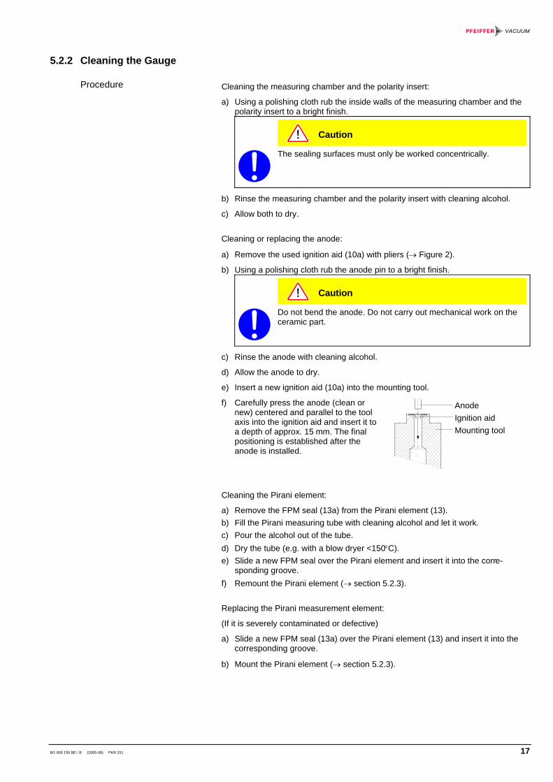
e) Insert a new ignition aid (10a) into the mounting tool.
f) Carefully press the anode (clean ornew) centered and parallel to the toolaxis into the ignition aid and insert it toa depth of approx. 15 mm. The finalpositioning is established after theanode is installed.
Cleaning the Pirani element:
a) Remove the FPM seal (13a) from the Pirani element (13).b) Fill the Pirani measuring tube with cleaning alcohol and let it work.c) Pour the alcohol out of the tube.d) Dry the tube (e.g. with a blow dryer <150°C).e) Slide a new FPM seal over the Pirani element and insert it into the corre-
sponding groove.f) Remount the Pirani element (→ section 5.2.3).
Replacing the Pirani measurement element:
(If it is severely contaminated or defective)
a) Slide a new FPM seal (13a) over the Pirani element (13) and insert it into thecorresponding groove.
b) Mount the Pirani element (→ section 5.2.3).
5.2.2 Cleaning the Gauge
Procedure
AnodeIgnition aidMounting tool

18 BG 805 155 BE / B (2005-08) PKR 251
a) Insert the FPM seal (11) with the support ring (12) centered into the measuringchamber (7). The sealing surface, seal, and ceramic part must be clean(→ Figure 2).
b) Carefully insert the anode (10) incl. ignition aid (10a) into the measuringchamber.
c) Insert the Pirani element (13) with the FPM seal (13a) slid over it into thecorresponding bore hole.
d) Carefully place the pressure piece (9) on the measuring chamber and tightenthem with the three hexagon socket screws (8) incl. lock washers (8a) uniformlyuntil the stop position is reached.
e) Position the ignition aid (10a) by pushing the mounting tool over the anode pinuntil the mechanical stop is reached.
f) Blow the particles in the measuring chamber with dry nitrogen (be careful tohold the measuring chamber with the flange pointing downwards).
g) Slide the polarity insert (6) into the measuring chamber until the mechanicalstop is reached.
h) Place the circlip (5) snugly fitting on the polarity insert.
Caution
Visually check that the anode pin is centered over the middle holeof the polarity insert (max. eccentricity = 0.5 mm).
i) If possible perform a leak test (leak rate <10-9 mbar l/s).
j) Mount the magnet unit (4) and lock it with the screw (3).
k) Carefully mount the electronics unit (2). (Make sure the pin of the Piranielement is properly plugged into the corresponding hole of the electronics unit.)
l) Push the electronics unit up to the mechanical stop and lock it with the hexagonsocket set screw (1).
m) Adjust the gauge (→ 14).
5.2.3 Reassembling the Gauge
Procedure

BG 805 155 BE / B (2005-08) PKR 251 19
Problem Possible cause RemedyMeasuring signalcontinually < 0.5 V"Error low".
No supply voltage. Turn on the powersupply.
Measuring signalcontinually > 9.5 V"Error high".
Pirani measurementelement defective(filament rupture).
Replace the Piranielement (→ 17).
Electronics unit not cor-rectly mounted.
Mount the electronicsunit correctly (→ 18).
The green lamp is ON andthe identification indicatesPirani-only mode(measuring signalcontinually > 4.0 V)"Pirani underrange".
The cold cathode dis-charge has not ignited.
Wait until the gasdischarge ignites (in caseof contamination withinsulation layers, the coldcathode may completelyfail to ignite). (Cleaning→ 17).
The PKR has only beenactivated withp < 3×10⁻⁹ mbar
Slightly increase thepressure.
Measuring signalcontinually > 5 V or display> 10-3 mbar althoughvacuum pressure is OK.
Pirani measurement cir-cuit not adjusted, e.g.due to severe contami-nation.
Readjust the Piranimeasurement circuit(→ 14). If adjustmentis impossible, replace thePirani element.
Measurement of heavygases.
Convert with thecorresponding formula(→ 26).
Severe outgassing in themeasuring chamber.
Clean the measuringchamber.
Measuring signal unstable. Gauge contaminated. Clean the gauge(→ 17).
5.3 What to Do in Case ofProblems
20 BG 805 155 BE / B (2005-08) PKR 251
6 Removing the Gauge From the Vacuum System
DANGER
Caution: contaminated partsContaminated parts can be detrimental to health.Before you begin to work, find out whether any parts are contaminated.Adhere to the relevant regulations and take the necessary precautionswhen handling contaminated parts.
Caution
Caution: vacuum componentDirt and damages impair the function of the vacuum component.When handling vacuum components, take appropriate measures toensure cleanliness and prevent damages.
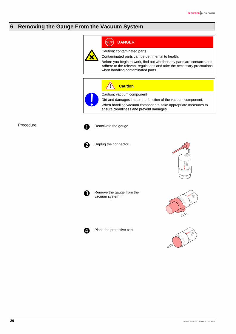
Deactivate the gauge.
Unplug the connector.
Com
pact
Ful
lRan
geTM
Gau
geVACU
UM
Remove the gauge from thevacuum system.
Place the protective cap.
Procedure
BG 805 155 BE / B (2005-08) PKR 251 21
7 Returning the Product
WARNING
Caution: forwarding contaminated productsProducts returned to Pfeiffer Vacuum for service or repair should, ifpossible, be free of harmful substances (e.g. radioactive, toxic, causticor microbiological). Otherwise, the type of contamination must bedeclared.Adhere to the forwarding regulations of all involved countries andforwarding companies and enclose a completed contaminationdeclaration.
Products that are not clearly declared as "free of harmful substances" are de-contaminated at the expense of the customer.
8 Accessories
Ordering numberConnection cable for Pfeiffer Vacuummeasurement unit for Compact Gauges
3 m 6 m10 m
Connection socket HirschmannGO 6 WF 6 contacts, angled, femaleMagnetic shielding
BG448250-TBG448251-TBG448252-TB4707283MA
PT443155-X

22 BG 805 155 BE / B (2005-08) PKR 251
9 Spare Parts
When ordering spare parts, always indicate:• the type of product• the manufacturing number given on the product nameplate• the position, description, and ordering number according to the spare parts list
The following parts are available as spare parts sets:
Pos. Description Ordering number
1213a1110a
Maintenance set, consisting of:1× support ring1× O-ring FPM 3.69 × 1.781× O-ring FPM 10.82 × 1.783× ignition aid
BN846 39-T
131213a1110a10
Repair set, consisting of:1× Pirani measurement element, cpl.1× support ring1× O-ring FPM 3.69 × 1.781× O-ring FPM 10.82 × 1.783× ignition aid1× anode, complete
BN846238-T
10aSet of ignition aids, consisting of:
10× ignition aidBN845995-T
Mounting tool for ignition aid BG510600
2 Electronics unit PKR 251 PT120140-T
Measuring system, completeDN 25 ISO-KF flangeDN 40 ISO-KF flangeDN 40 CF-F flange
BN846469-TBN846470-TBN846471-T
Exchange gauge(return defective gauge to Pfeiffer Vacuum)
DN 25 ISO-KF flangeDN 40 ISO-KF flangeDN 40 CF-F flange
PTR26000-APTR26001-APTR26002-A
1
2
34
7
8a8
9
12
1010a
11
1313a

BG 805 155 BE / B (2005-08) PKR 251 23
10 Disposal
N
WARNING
Caution: substances detrimental to the environmentProducts, operating materials etc. may have to be specially disposedof.For environmentally compatible disposal, please contact your nearestPfeiffer Vacuum Service Center.
24 BG 805 155 BE / B (2005-08) PKR 251
Appendix
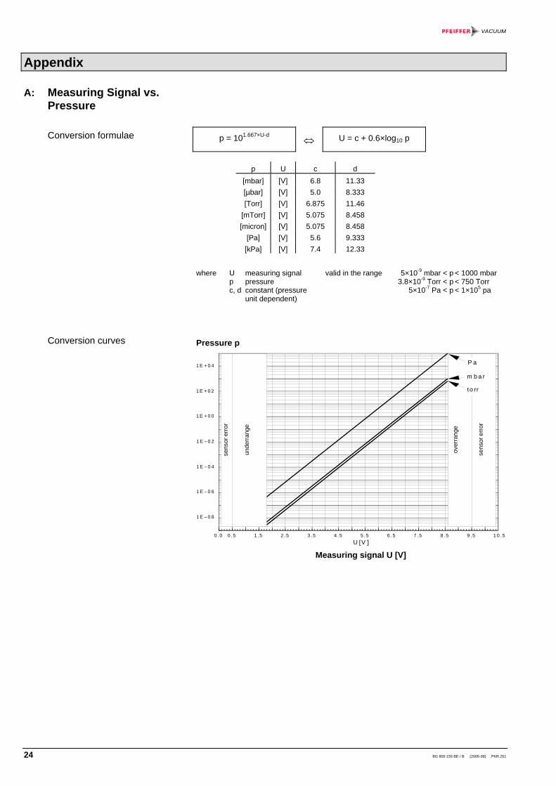
p = 101.667×U-d⇔ U = c + 0.6×log10 p
p U c d[mbar] [V] 6.8 11.33[µbar] [V] 5.0 8.333[Torr] [V] 6.875 11.46
[mTorr] [V] 5.075 8.458[micron] [V] 5.075 8.458
[Pa] [V] 5.6 9.333[kPa] [V] 7.4 12.33
where U measuring signalp pressurec, d constant (pressure
unit dependent)
valid in the range 5×10⁻⁹ mbar < p3.8×10-9 Torr < p
5×10⁻⁷ Pa < p
< 1000 mbar< 750 Torr< 1×10⁵ pa
Pressure p
1 E + 0 4
1 E + 0 2
1 E + 0 0
U [V0 .0 0 .5 1 .5 2 .5 3 .5 4 .5 5 .5 6 .5 7 .5 8 .5 9 .5 1 0 .5
1 E – 0 2
1 E – 0 4
1 E – 0 6
1 E – 0 8
sens
or e
rror
unde
rran
ge
over
rang
e
sens
or e
rror
P a
m b a r
to rr
Measuring signal U [V]
A: Measuring Signal vs.Pressure
Conversion formulae
Conversion curves

BG 805 155 BE / B (2005-08) PKR 251 25
Measuringsignal U [V] [mbar]
Pressure p[Torr] [Pa]
< 0.5 Sensor error0.5 ... 1.82 Underrange
1.82 2.0 2.63.2 3.8 4.4 5.0 5.6 6.2 6.8 7.4 8.0 8.6
5.0×10⁻⁹
1.0×10⁻⁸
1.0×10⁻⁷
1.0×10⁻⁶
1.0×10⁻⁵
1.0×10⁻⁴
1.0×10⁻³
1.0×10⁻²
0.11.010100
1000
3.8×10⁻⁹
7.5×10⁻⁹
7.5×10⁻⁸
7.5×10⁻⁷
7.5×10⁻⁶
7.5×10⁻⁵
7.5×10⁻⁴
7.5×10⁻³
7.5×10⁻⁴
0.757.575750
5.0×10⁻⁷
1.0×10⁻⁶
1.0×10⁻⁵
1.0×10⁻⁴
1.0×10⁻³
1.0×10⁻²
0.11.010100
10001.0×104
1.0×10⁵
8.6 ... 9.5 Overrange9.5 ... 10.5 Sensor error (Pirani defective)
Conversion table

26 BG 805 155 BE / B (2005-08) PKR 251
Pressure indicated (gauge calibrated for air)
Pressure indicated (gauge calibrated for air)
B: Gas Type Dependence
Indication range above10-2 mbar(Pirani only mode)
Indication range10-6 ... 0.1 mbar
BG 805 155 BE / B (2005-08) PKR 251 27
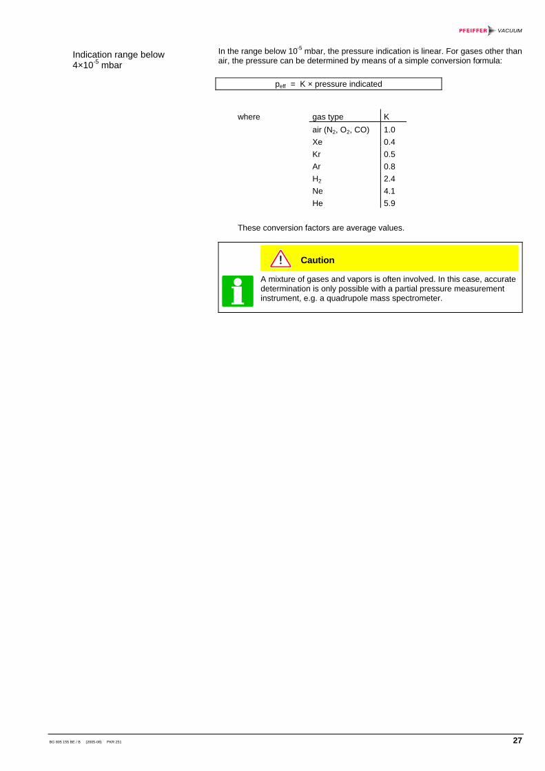
In the range below 10-5 mbar, the pressure indication is linear. For gases other thanair, the pressure can be determined by means of a simple conversion formula:
peff = K × pressure indicated
where gas type Kair (N2, O2, CO) 1.0Xe 0.4Kr 0.5Ar 0.8H2 2.4Ne 4.1He 5.9
These conversion factors are average values.
Caution
A mixture of gases and vapors is often involved. In this case, accuratedetermination is only possible with a partial pressure measurementinstrument, e.g. a quadrupole mass spectrometer.
Indication range below4×10-5 mbar

28 BG 805 155 BE / B (2005-08) PKR 251
Declaration of Contamination
The service, repair, and/or disposal of vacuum equipment and components will only be carried out if a correctly completed declaration has been submitted. Non-completion will result in delay.This declaration may only be completed (in block letters) and signed by authorized and qualified staff.
Description of product Type Part number Serial number
Reason for return
Legally binding declaration: We hereby declare that the information on this form is complete and accurate and that we will assume any further costs that may arise. The contaminated product will be dispatched in accordance with the applicable regulations.
Organization/company Address Post code, place Phone Fax Email Name
Date and legally binding signature Company stamp
Copies:Original for addresee - 1 copy for accompanying documents - 1 copy for file of sender
Operating fluid(s) used (Must be drained before shipping.)
Harmful substances, gases and/or by-productsPlease list all substances, gases, and by-products which the product may have come into contact with:Trade/product name Chemical name
(or symbol)Precautions associatedwith substance
Action if human contact
The product is free of any sub-stances which are damaging tohealth. yes
Used in copper processno yes Seal product in plastic bag and
mark it with a corresponding label.
This form can be downloaded from our website.
2) Products thus contami- nated will not be ac- cepted without written evidence of decontami- nation.
1) or not containing any amount of hazardous residues that exceed the permissible ex- posure limits
Process related contamination of product: toxic no 1) yes caustic no 1) yes biological hazard no yes 2) explosive no yes 2) radioactive no yes 2) other harmful substances no 1) yes

BG 805 155 BE / B (2005-08) PKR 251 29
Notes

30 BG 805 155 BE / B (2005-08) PKR 251
Notes

BG 805 155 BE / B (2005-08) PKR 251 31
Notes

Berliner Strasse 43D–35614 AsslarDeutschlandTel +49 (0) 6441 802-0Fax +49 (0) 6441 802-202
Original: German BG.805 155 BD / B (2005-08) [email protected]
bg805155be/ b www.pfeiffer-vacuum.net


