100
Compact Heat Exchanger Design, Characteristics and Trends 1. Introduction NARSA Heavy Duty Heating and Cooling Conference Sept 2012 Ann Arbor, MI Instructor: Joe Borghese
Compact Heat Exchanger Design, Characteristics and Trends
1. Introduction
NARSA Heavy Duty Heating and Cooling Conference Sept 2012 Ann Arbor, MI
Instructor: Joe Borghese
NARSA Compact Heat Exchanger Design Seminar September 2012
Copyright
• This presentation material presented for the NARSA Education Seminar is copyrighted material
• Original material copyright 2012 © Joseph Borghese
Page 2
NARSA Compact Heat Exchanger Design Seminar September 2012
Course Outline
• Introduction • Functions and Types of Heat Exchangers • Heat Exchanger Design Process • Heat Transfer and Pressure Drop Analyses • Heat Exchanger Surface Characteristics • Engine Cooling Systems • Air Conditioning Systems • Recent Developments • Concluding Remarks
Page 3
NARSA Compact Heat Exchanger Design Seminar September 2012
References
1. R.K. Shah and D.P. Sekulic, Fundamentals of Heat Exchanger Design, John Wiley, New York, 2003
2. Kays and London, Compact Heat Exchangers, McGraw-Hill, New York, 3rd Edition, 1984
3. Compact Heat Exchangers for the Process Industries, R.K. Shah, Editor, Begell House, Inc. New York, 1997
Page 4
NARSA Compact Heat Exchanger Design Seminar September 2012
Acknowledgement
The author would like to acknowledge the support of Ramesh K. Shah who originally presented the SAE course “Compact Heat Exchangers for Automotive Applications”
Page 5

Compact Heat Exchanger Design, Characteristics and Trends
2. Heat Exchanger Functions and
Types
NARSA Heavy Duty Heating and Cooling Conference Sept 2012 Ann Arbor, MI
Instructor: Joe Borghese
NARSA Compact Heat Exchanger Design Seminar September 2012
Heat Exchanger Defined
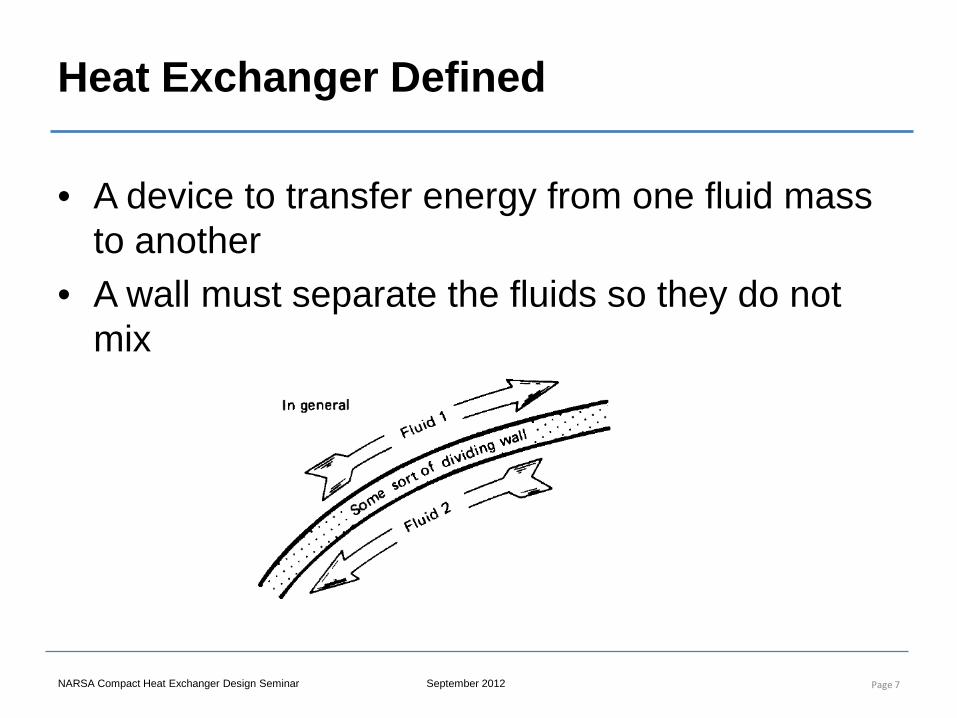
• A device to transfer energy from one fluid mass to another
• A wall must separate the fluids so they do not mix
Page 7
NARSA Compact Heat Exchanger Design Seminar September 2012
Why it is not that simple…
• Perform the required heat transfer AND – Minimize size and weight – Minimize pressure drop – Meet required life – Be resistant to fouling and contamination – Minimize cost
Page 8
NARSA Compact Heat Exchanger Design Seminar September 2012
Compact Heat Exchangers
• Compact heat exchangers are a class of heat exchangers that incorporate a large amount of heat transfer surface area per unit volume
• Most automotive heat exchangers would come into the compact heat exchanger category since space is an extreme constraint for automotive applications.
Page 9
NARSA Compact Heat Exchanger Design Seminar September 2012
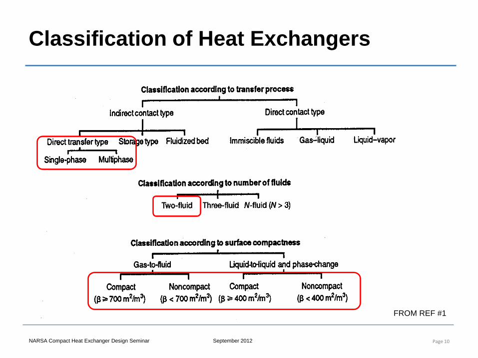
Classification of Heat Exchangers
Page 10
FROM REF #1
NARSA Compact Heat Exchanger Design Seminar September 2012
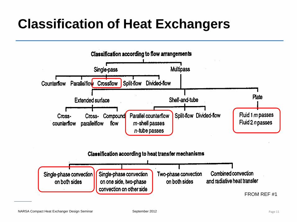
Classification of Heat Exchangers
Page 11
FROM REF #1
NARSA Compact Heat Exchanger Design Seminar September 2012
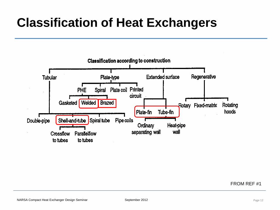
Classification of Heat Exchangers
Page 12
FROM REF #1
NARSA Compact Heat Exchanger Design Seminar September 2012
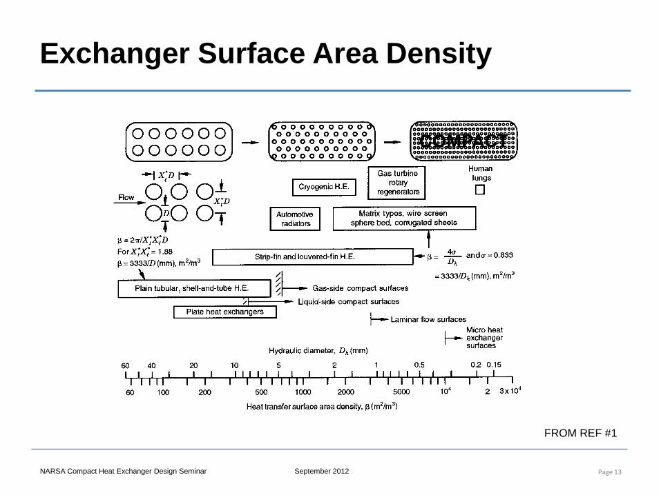
Exchanger Surface Area Density
Page 13
FROM REF #1
NARSA Compact Heat Exchanger Design Seminar September 2012
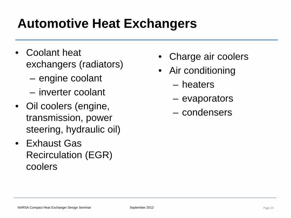
Automotive Heat Exchangers
• Coolant heat exchangers (radiators) – engine coolant – inverter coolant
• Oil coolers (engine, transmission, power steering, hydraulic oil)
• Exhaust Gas Recirculation (EGR) coolers
Page 14
• Charge air coolers • Air conditioning
– heaters – evaporators – condensers
NARSA Compact Heat Exchanger Design Seminar September 2012
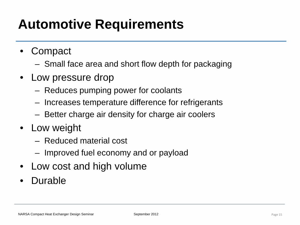
Automotive Requirements
• Compact – Small face area and short flow depth for packaging
• Low pressure drop – Reduces pumping power for coolants – Increases temperature difference for refrigerants – Better charge air density for charge air coolers
• Low weight – Reduced material cost – Improved fuel economy and or payload
• Low cost and high volume • Durable
Page 15
NARSA Compact Heat Exchanger Design Seminar September 2012
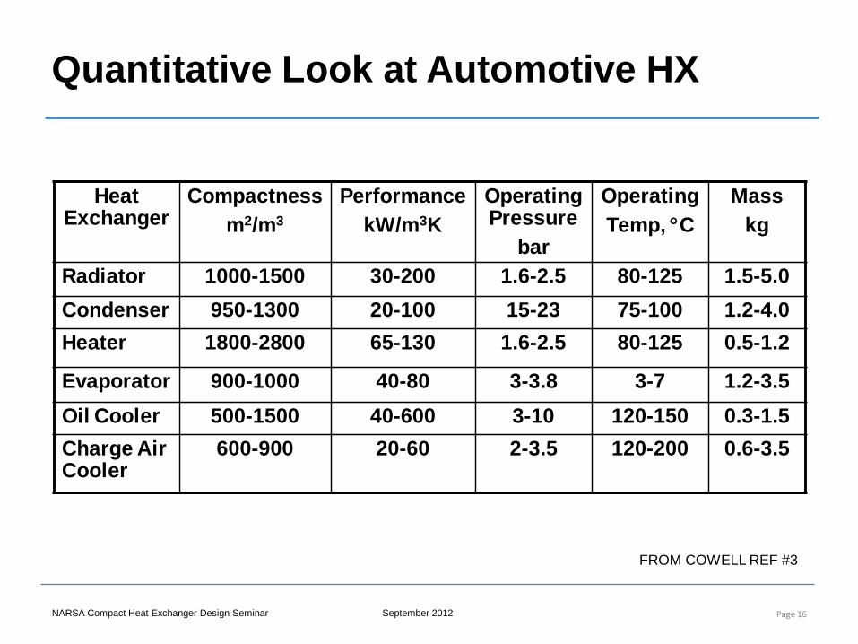
Quantitative Look at Automotive HX
Page 16
Heat Exchanger
Compactnessm2/m3
PerformancekW/m3K
Operating Pressure
bar
OperatingTemp, °C
Masskg
Radiator 1000-1500 30-200 1.6-2.5 80-125 1.5-5.0Condenser 950-1300 20-100 15-23 75-100 1.2-4.0Heater 1800-2800 65-130 1.6-2.5 80-125 0.5-1.2
Evaporator 900-1000 40-80 3-3.8 3-7 1.2-3.5Oil Cooler 500-1500 40-600 3-10 120-150 0.3-1.5Charge Air Cooler
600-900 20-60 2-3.5 120-200 0.6-3.5
FROM COWELL REF #3
Compact Heat Exchanger Design, Characteristics and Trends
2. Design Process for Compact Heat
Exchangers
NARSA Heavy Duty Heating and Cooling Conference Sept 2012 Ann Arbor, MI
Instructor: Joe Borghese

NARSA Compact Heat Exchanger Design Seminar September 2012
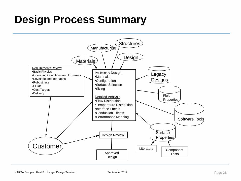
Design Process Summary
Page 18
Preliminary Design •Materials •Configuration •Surface Selection •Sizing Detailed Analysis •Flow Distribution •Temperature Distribution •Interface Effects •Conduction Effects •Performance Mapping
Customer
Requirements Review •Basic Physics •Operating Conditions and Extremes •Envelope and Interfaces •Robustness •Fluids •Cost Targets •Delivery
Design Review
Approved Design
Manufacturing
Design Materials
Structures
Fluid Properties
Legacy Designs
Surface Properties
Software Tools
Component Tests
Literature
NARSA Compact Heat Exchanger Design Seminar September 2012
Requirements
• Establish design inputs – Fluids – Operating conditions – Available envelope and ducting interfaces – Environmental conditions – Manufacturing options
• Establish and rank design goals – Performance – Size and weight – Cost – Durability
Page 19
NARSA Compact Heat Exchanger Design Seminar September 2012
Fluids
• Generally decided at system level • Heat sink fluid is often ultimately air
– Low density gas – Low specific heat
• Heat sources often liquid cooled – Ethylene-Glycol / Water mixtures – Propylene-Glycol / Water mixtures – Engine oil – Hydraulic oil – Refrigerants (R134a)
Page 20
NARSA Compact Heat Exchanger Design Seminar September 2012
Design Operating Conditions
• Establish operating profile – Start, idle, accel, cruise, decel, climb, descend, idle,
shutdown – Standard day, hot day, cold day and extremes – Humidity – Altitude (sea level to 10,000 ft ?)
• From operating profile choose design conditions, for example: – Extreme hot day (120°F) at 7000 ft – High heat load (climb) – Low flows (idle) Page 21
NARSA Compact Heat Exchanger Design Seminar September 2012
Envelope and Ducting
• Establish dimensions available for heat exchanger core and fluid manifolds – Envelope may determine heat exchanger surface
selection • Determine if fluid interfaces are fixed or can the
application accommodate changes – Fluid interfaces may dictate heat exchanger flow
arrangement • Flexibility in envelope and ducting will allow
optimization for performance, size, weight
Page 22
NARSA Compact Heat Exchanger Design Seminar September 2012
Environmental Conditions
• Vibration • Duct and mount loads • Sand, dust, humidity, corrosive fluids • Fouling • Temperature and pressure extremes
Page 23
NARSA Compact Heat Exchanger Design Seminar September 2012
Manufacturing Considerations
• What quantities are involved? – 10’s, 100’s, 1,000’s, >10,000
• What are the available manufacturing processes for: – Details (fins, tubes, plates, bars, mounts, ports) – Core brazing, joining – Manifold forming and joining
• Design can be pulled from what can be built • Design can push new manufacturing technology
Page 24
NARSA Compact Heat Exchanger Design Seminar September 2012
Design Goals and Optimization • Rank design variables with customer
– Envelope, size – Interfaces – Weight – Durability – Heat transfer rate – Hot side pressure drop – Cold side pressure drop – Cost
• Select what is to be optimized, for example: – Minimize size and cost while meeting heat transfer and pressure
drops – Maximize durability while meeting heat transfer and pressure
drops
Page 25
NARSA Compact Heat Exchanger Design Seminar September 2012
Design Process Summary
Page 26
Preliminary Design •Materials •Configuration •Surface Selection •Sizing Detailed Analysis •Flow Distribution •Temperature Distribution •Interface Effects •Conduction Effects •Performance Mapping
Customer
Requirements Review •Basic Physics •Operating Conditions and Extremes •Envelope and Interfaces •Robustness •Fluids •Cost Targets •Delivery
Design Review
Approved Design
Manufacturing
Design Materials
Structures
Fluid Properties
Legacy Designs
Surface Properties
Software Tools
Component Tests
Literature
Compact Heat Exchanger Design, Characteristics and Trends
4. Heat Exchanger Performance
Analysis
NARSA Heavy Duty Heating and Cooling Conference Sept 2012 Ann Arbor, MI
Instructor: Joe Borghese
NARSA Compact Heat Exchanger Design Seminar September 2012
Performance Analysis Overview
• Modes of heat transfer • Heat transfer within a heat exchanger • Conductance • Heat capacity rate • Impact of flow arrangement • Estimating heat rejection and exit temperatures • Pressure losses
Page 28
NARSA Compact Heat Exchanger Design Seminar September 2012
Heat Transfer
• The transfer of energy in the form of heat • Energy (heat) is always conserved
– 1st law of thermodynamics – Heat given up by hot fluid = heat gained by cold fluid
• Heat flows from hot to cold – 2nd law of thermodynamics – Heat transfer rate is proportional to the temperature
difference
Page 29
NARSA Compact Heat Exchanger Design Seminar September 2012
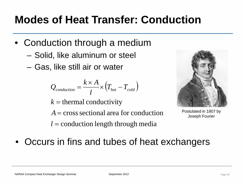
Modes of Heat Transfer: Conduction
• Conduction through a medium – Solid, like aluminum or steel – Gas, like still air or water
Page 30
( )
media throughlength conductionconductionfor area sectional cross
tyconductivi thermal
===
−××
=
lAk
TTl
AkQ coldhotconduction
• Occurs in fins and tubes of heat exchangers
Postulated in 1807 by Joseph Fourier
NARSA Compact Heat Exchanger Design Seminar September 2012
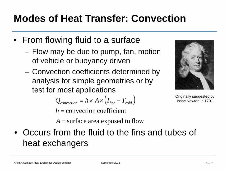
Modes of Heat Transfer: Convection
• From flowing fluid to a surface – Flow may be due to pump, fan, motion
of vehicle or buoyancy driven – Convection coefficients determined by
analysis for simple geometries or by test for most applications
Page 31
( )
flow toexposedarea surfacetcoefficien convection
==
−××=
Ah
TTAhQ coldhotconvection
• Occurs from the fluid to the fins and tubes of heat exchangers
Originally suggested by Issac Newton in 1701
NARSA Compact Heat Exchanger Design Seminar September 2012
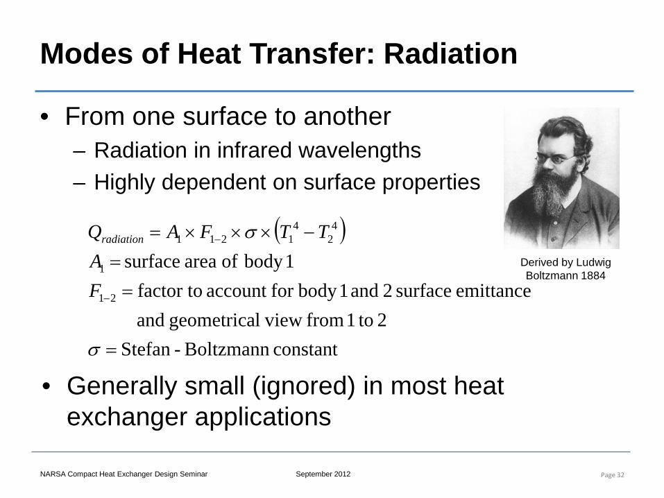
Modes of Heat Transfer: Radiation
• From one surface to another – Radiation in infrared wavelengths – Highly dependent on surface properties
Page 32
( )
constant Boltzmann-Stefan2 to1 from view lgeometrica and
emittance surface 2 and 1body for account factor to1body ofarea surface
21
1
42
41211
=
==
−×××=
−
−
σ
σ
FA
TTFAQradiation
• Generally small (ignored) in most heat exchanger applications
Derived by Ludwig Boltzmann 1884
NARSA Compact Heat Exchanger Design Seminar September 2012
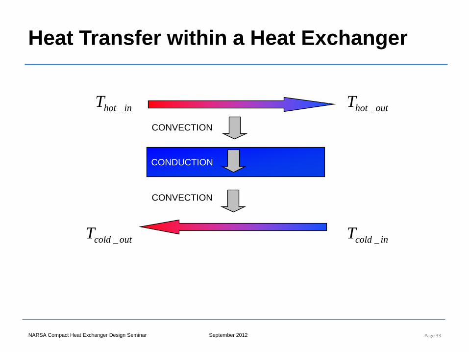
Heat Transfer within a Heat Exchanger
Page 33
CONVECTION
CONDUCTION
CONVECTION
inhotT _ outhotT _
incoldT _outcoldT _
NARSA Compact Heat Exchanger Design Seminar September 2012
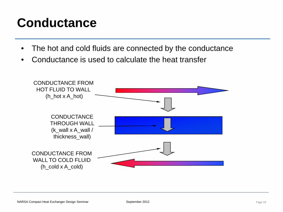
Conductance
Page 34
CONDUCTANCE FROM HOT FLUID TO WALL
(h_hot x A_hot)
CONDUCTANCE FROM WALL TO COLD FLUID
(h_cold x A_cold)
CONDUCTANCE THROUGH WALL (k_wall x A_wall / thickness_wall)
• The hot and cold fluids are connected by the conductance • Conductance is used to calculate the heat transfer
NARSA Compact Heat Exchanger Design Seminar September 2012
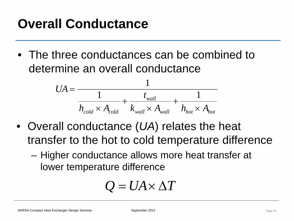
Overall Conductance
• The three conductances can be combined to determine an overall conductance
Page 35
hothotwallwall
wall
coldcold AhAkt
Ah
UA
×+
×+
×
= 111
• Overall conductance (UA) relates the heat transfer to the hot to cold temperature difference – Higher conductance allows more heat transfer at
lower temperature difference
TUAQ ∆×=
NARSA Compact Heat Exchanger Design Seminar September 2012
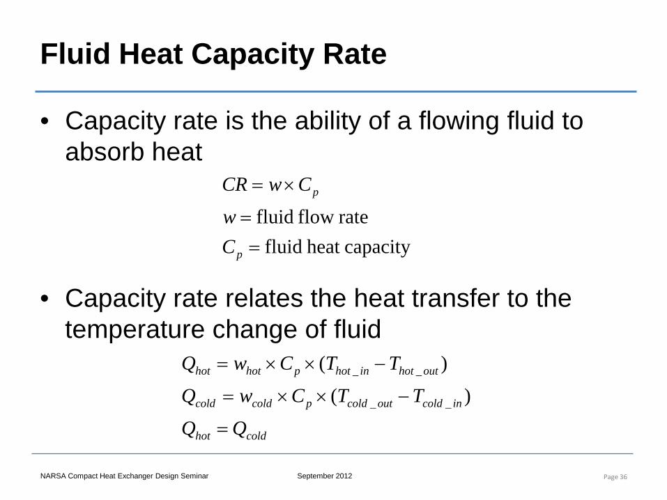
Fluid Heat Capacity Rate
• Capacity rate is the ability of a flowing fluid to absorb heat
Page 36
capacityheat fluidrateflow fluid
==
×=
p
p
Cw
CwCR
• Capacity rate relates the heat transfer to the temperature change of fluid
coldhot
incoldoutcoldpcoldcold
outhotinhotphothot
QQTTCwQ
TTCwQ
=
−××=
−××=
)()(
__
__
NARSA Compact Heat Exchanger Design Seminar September 2012
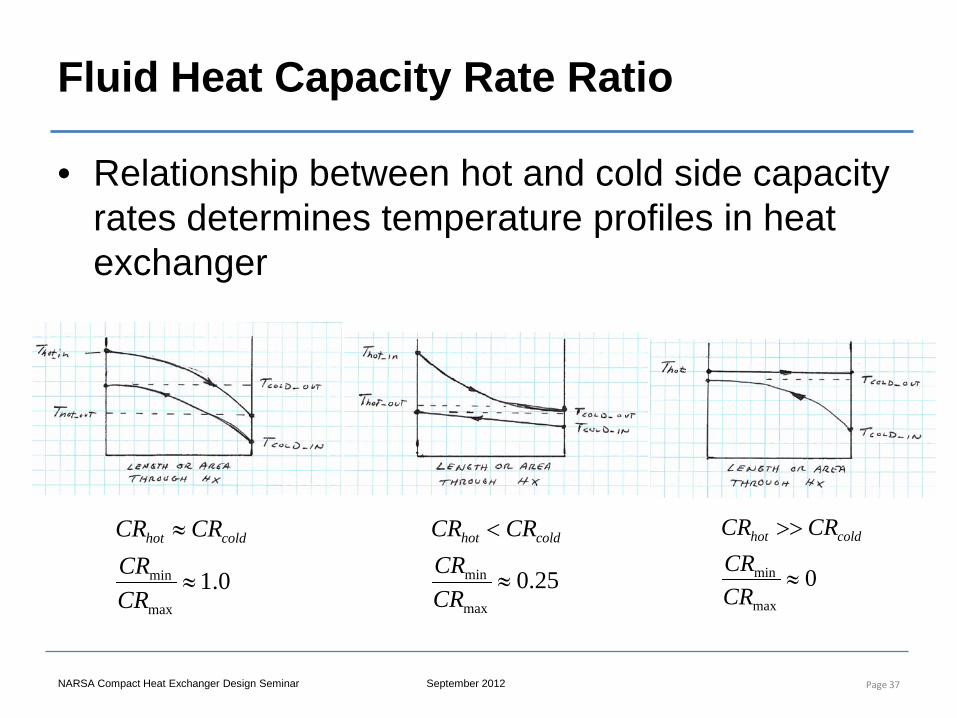
Fluid Heat Capacity Rate Ratio
Page 37
0.1max
min ≈
≈
CRCR
CRCR coldhot
25.0max
min ≈
<
CRCR
CRCR coldhot
0max
min ≈
>>
CRCR
CRCR coldhot
• Relationship between hot and cold side capacity rates determines temperature profiles in heat exchanger
NARSA Compact Heat Exchanger Design Seminar September 2012
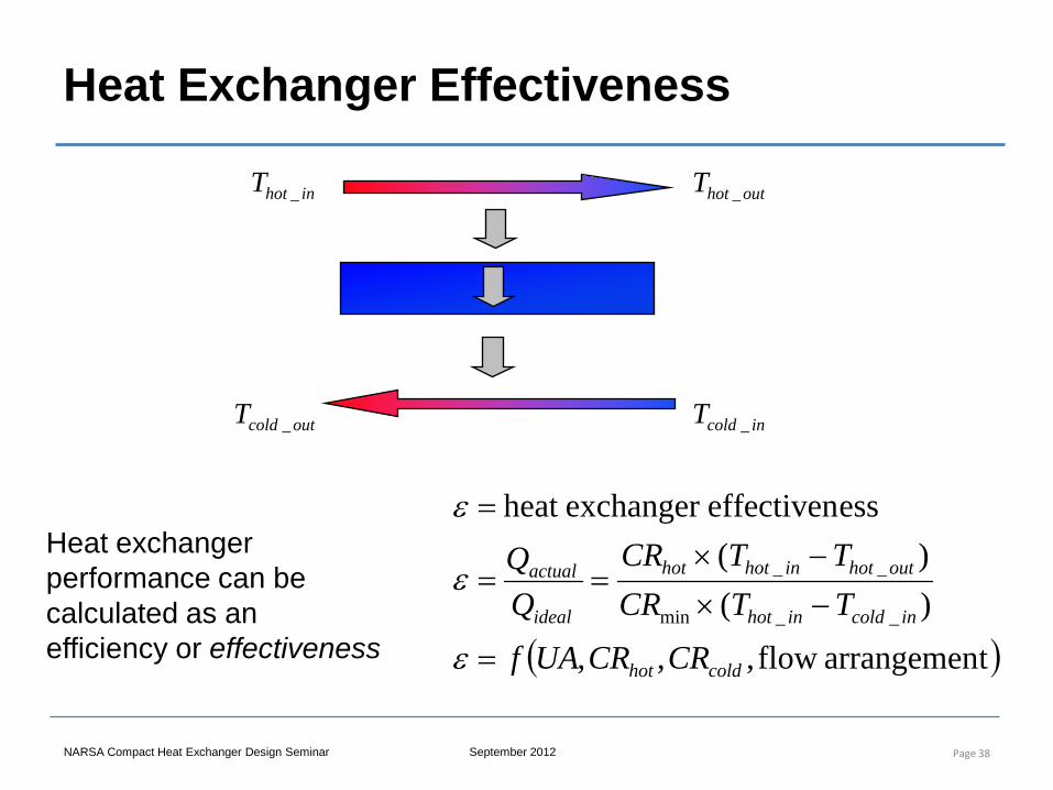
Heat Exchanger Effectiveness
Page 38
inhotT _ outhotT _
incoldT _outcoldT _
( )tarrangemenflow ,,,)()(
esseffectivenexchanger heat
__min
__
coldhot
incoldinhot
outhotinhothot
ideal
actual
CRCRUAfTTCRTTCR
=
−×−×
==
=
ε
ε
εHeat exchanger performance can be calculated as an efficiency or effectiveness
NARSA Compact Heat Exchanger Design Seminar September 2012
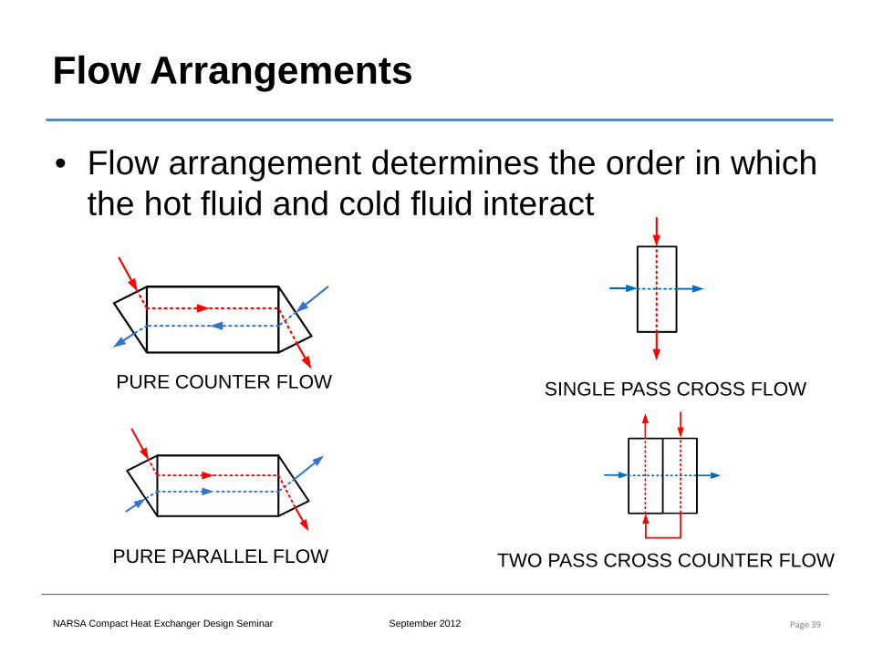
Flow Arrangements
• Flow arrangement determines the order in which the hot fluid and cold fluid interact
Page 39
PURE COUNTER FLOW
PURE PARALLEL FLOW
SINGLE PASS CROSS FLOW
TWO PASS CROSS COUNTER FLOW
NARSA Compact Heat Exchanger Design Seminar September 2012
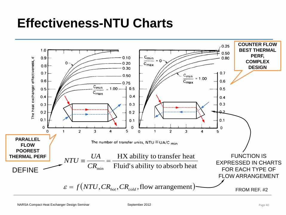
COUNTER FLOW BEST THERMAL
PERF, COMPLEX
DESIGN
PARALLEL FLOW
POOREST THERMAL PERF
Effectiveness-NTU Charts
Page 40
( )tarrangemenflow ,,,
heat absorb ability to sFluid'heat transfer ability to HX
min
coldhot CRCRNTUf
CRUANTU
=
=≡
ε
DEFINE
FUNCTION IS EXPRESSED IN CHARTS
FOR EACH TYPE OF FLOW ARRANGEMENT
FROM REF. #2
NARSA Compact Heat Exchanger Design Seminar September 2012
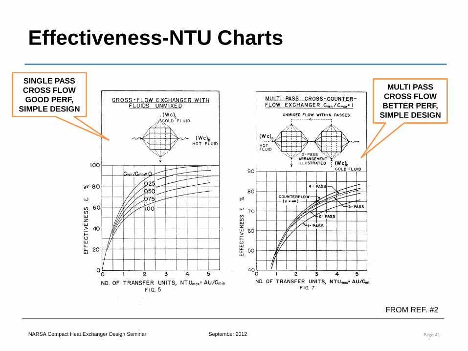
Effectiveness-NTU Charts
Page 41
SINGLE PASS CROSS FLOW GOOD PERF,
SIMPLE DESIGN
MULTI PASS CROSS FLOW BETTER PERF,
SIMPLE DESIGN
FROM REF. #2
NARSA Compact Heat Exchanger Design Seminar September 2012
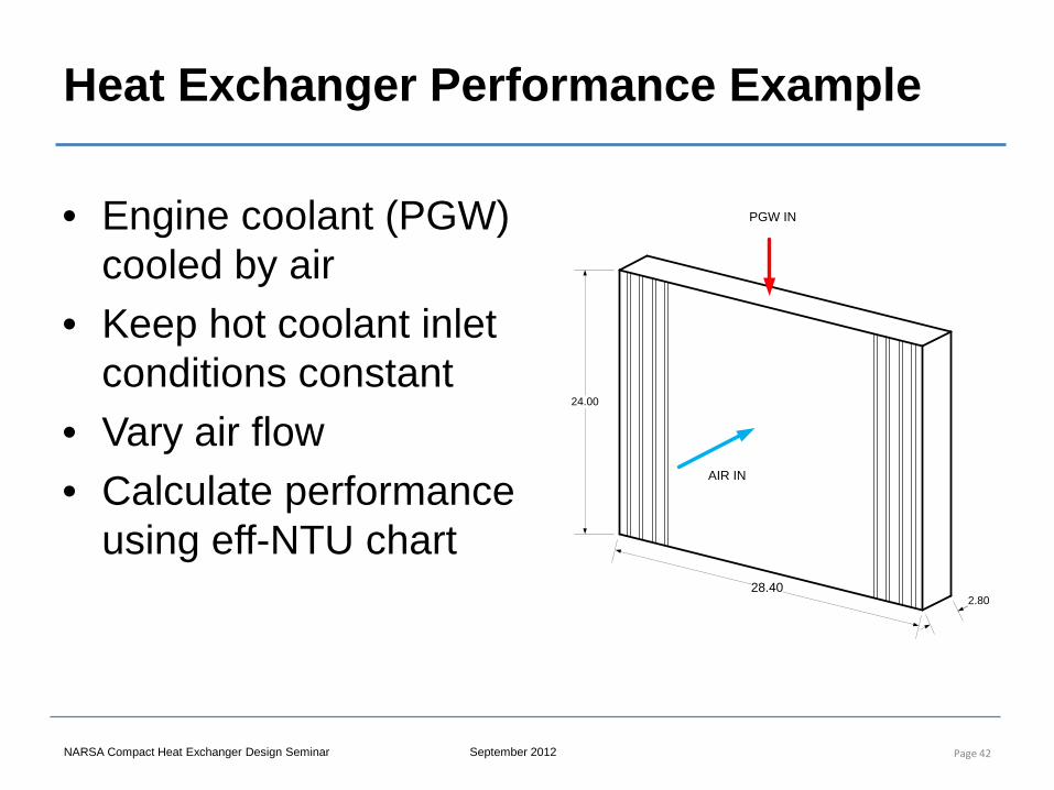
Heat Exchanger Performance Example
• Engine coolant (PGW) cooled by air
• Keep hot coolant inlet conditions constant
• Vary air flow • Calculate performance
using eff-NTU chart
Page 42
24.00
28.402.80
PGW IN
AIR IN
NARSA Compact Heat Exchanger Design Seminar September 2012
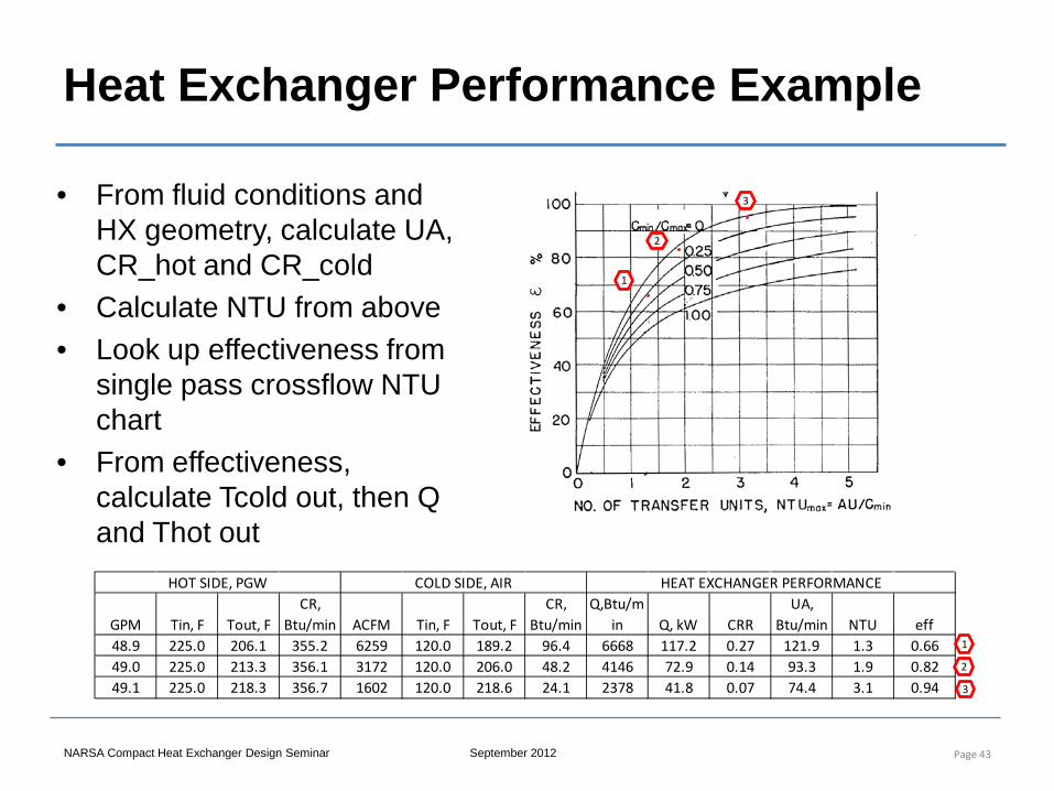
Heat Exchanger Performance Example
• From fluid conditions and HX geometry, calculate UA, CR_hot and CR_cold
• Calculate NTU from above • Look up effectiveness from
single pass crossflow NTU chart
• From effectiveness, calculate Tcold out, then Q and Thot out
Page 43
GPM Tin, F Tout, FCR,
Btu/min ACFM Tin, F Tout, FCR,
Btu/minQ,Btu/m
in Q, kW CRRUA,
Btu/min NTU eff48.9 225.0 206.1 355.2 6259 120.0 189.2 96.4 6668 117.2 0.27 121.9 1.3 0.6649.0 225.0 213.3 356.1 3172 120.0 206.0 48.2 4146 72.9 0.14 93.3 1.9 0.8249.1 225.0 218.3 356.7 1602 120.0 218.6 24.1 2378 41.8 0.07 74.4 3.1 0.94
HOT SIDE, PGW COLD SIDE, AIR HEAT EXCHANGER PERFORMANCE
1
2
3
1
2
3
NARSA Compact Heat Exchanger Design Seminar September 2012
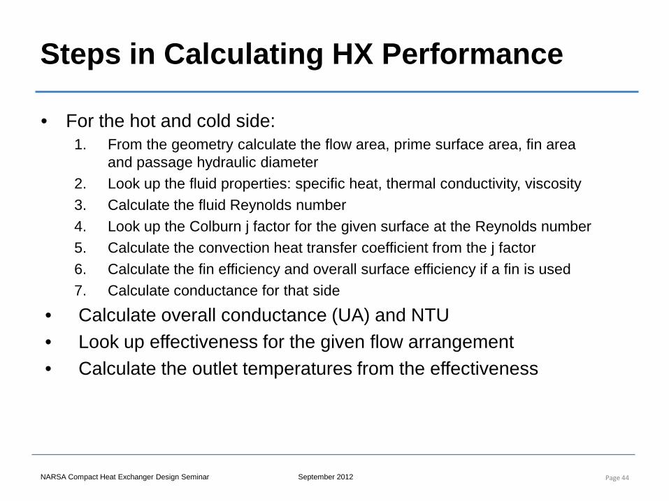
Steps in Calculating HX Performance
• For the hot and cold side: 1. From the geometry calculate the flow area, prime surface area, fin area
and passage hydraulic diameter 2. Look up the fluid properties: specific heat, thermal conductivity, viscosity 3. Calculate the fluid Reynolds number 4. Look up the Colburn j factor for the given surface at the Reynolds number 5. Calculate the convection heat transfer coefficient from the j factor 6. Calculate the fin efficiency and overall surface efficiency if a fin is used 7. Calculate conductance for that side
• Calculate overall conductance (UA) and NTU • Look up effectiveness for the given flow arrangement • Calculate the outlet temperatures from the effectiveness
Page 44
NARSA Compact Heat Exchanger Design Seminar September 2012
Heat Exchanger Pressure Losses
• Pressure loss breakdown: – Inlet duct to manifold – Contraction from manifold into core – Friction within core – Acceleration loss due to density change – Expansion from core into manifold – Manifold to outlet duct
• Want to keep duct losses to minimum since they don’t aid the primary objective of heat transfer
Page 45
NARSA Compact Heat Exchanger Design Seminar September 2012
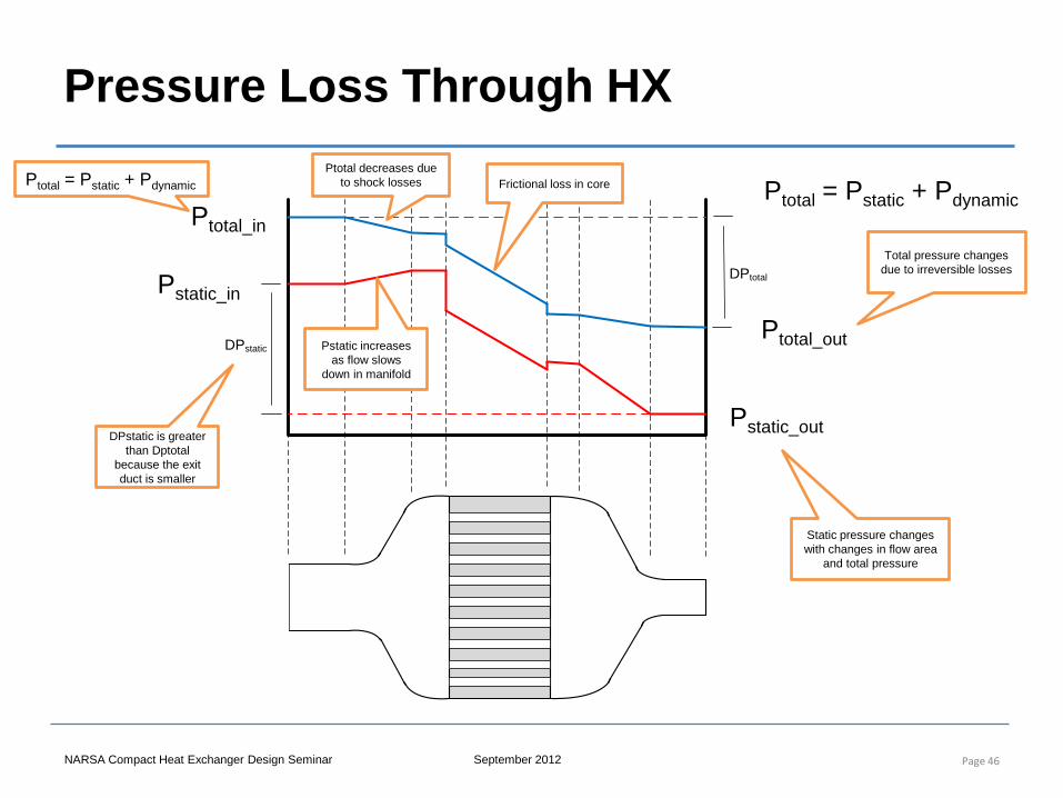
Pressure Loss Through HX
Page 46
DPtotal
DPstatic
Ptotal_in
Ptotal_out
Pstatic_in
Pstatic_out
Ptotal = Pstatic + Pdynamic
Pstatic increases as flow slows
down in manifold
Ptotal decreases due to shock losses
DPstatic is greater than Dptotal
because the exit duct is smaller
Ptotal = Pstatic + Pdynamic
Static pressure changes with changes in flow area
and total pressure
Total pressure changes due to irreversible losses
Frictional loss in core
NARSA Compact Heat Exchanger Design Seminar September 2012
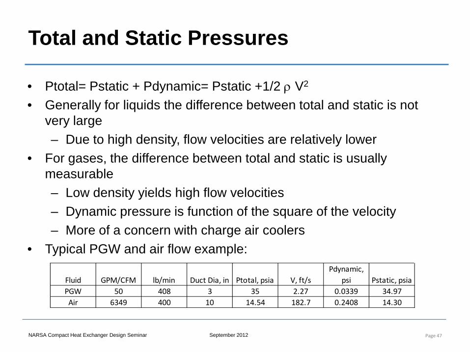
Total and Static Pressures
• Ptotal= Pstatic + Pdynamic= Pstatic +1/2 ρ V2
• Generally for liquids the difference between total and static is not very large – Due to high density, flow velocities are relatively lower
• For gases, the difference between total and static is usually measurable – Low density yields high flow velocities – Dynamic pressure is function of the square of the velocity – More of a concern with charge air coolers
• Typical PGW and air flow example:
Page 47
Fluid GPM/CFM lb/min Duct Dia, in Ptotal, psia V, ft/sPdynamic,
psi Pstatic, psiaPGW 50 408 3 35 2.27 0.0339 34.97Air 6349 400 10 14.54 182.7 0.2408 14.30
NARSA Compact Heat Exchanger Design Seminar September 2012
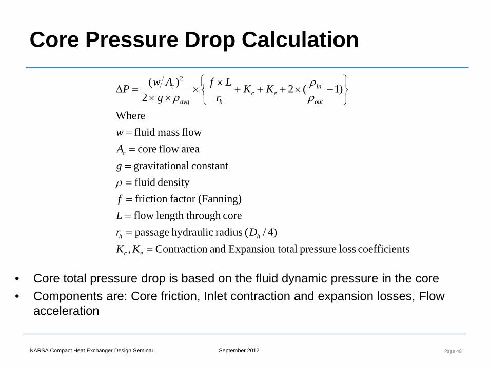
Core Pressure Drop Calculation
Page 48
tscoefficien loss pressure total Expansionand nContractio,)4/( radius hydraulic passage
core throughlengthflow (Fanning)factor friction
density fluidconstant nalgravitatio
areaflow coreflow mass fluid
Where
)1(22
)( 2
========
−×+++×
×××
=∆
ec
hh
c
out
inec
havg
c
KKDr
Lf
gAw
KKr
Lfg
AwP
ρ
ρρ
ρ
• Core total pressure drop is based on the fluid dynamic pressure in the core • Components are: Core friction, Inlet contraction and expansion losses, Flow
acceleration
NARSA Compact Heat Exchanger Design Seminar September 2012
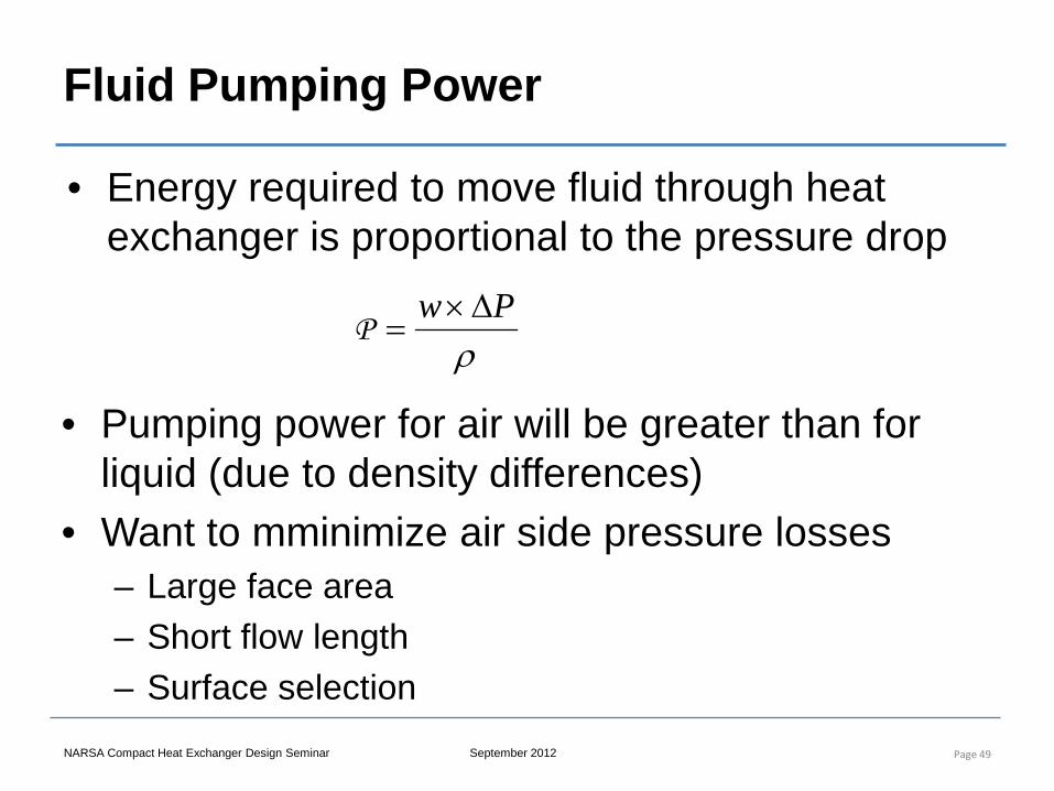
Fluid Pumping Power
• Energy required to move fluid through heat exchanger is proportional to the pressure drop
Page 49
ρPw ∆×
=P
• Pumping power for air will be greater than for liquid (due to density differences)
• Want to mminimize air side pressure losses – Large face area – Short flow length – Surface selection
Compact Heat Exchanger Design, Characteristics and Trends
5. Heat Exchanger Surfaces
NARSA Heavy Duty Heating and Cooling Conference Sept 2012 Ann Arbor, MI
Instructor: Joe Borghese
NARSA Compact Heat Exchanger Design Seminar September 2012
Surface Classification and Selection
• Surface classification: – Prime or extended surface – Plain or enhanced surface
• Surface selected according to – HX type (tubular, bar plate, plate, etc.) – Pressure containment – Contamination – Performance and design optimization
Page 51
NARSA Compact Heat Exchanger Design Seminar September 2012
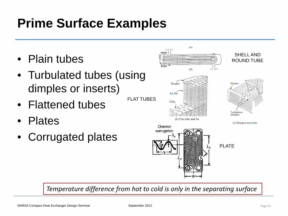
Prime Surface Examples
• Plain tubes • Turbulated tubes (using
dimples or inserts) • Flattened tubes • Plates • Corrugated plates
Page 52
Temperature difference from hot to cold is only in the separating surface
SHELL AND ROUND TUBE
FLAT TUBES
PLATE
NARSA Compact Heat Exchanger Design Seminar September 2012
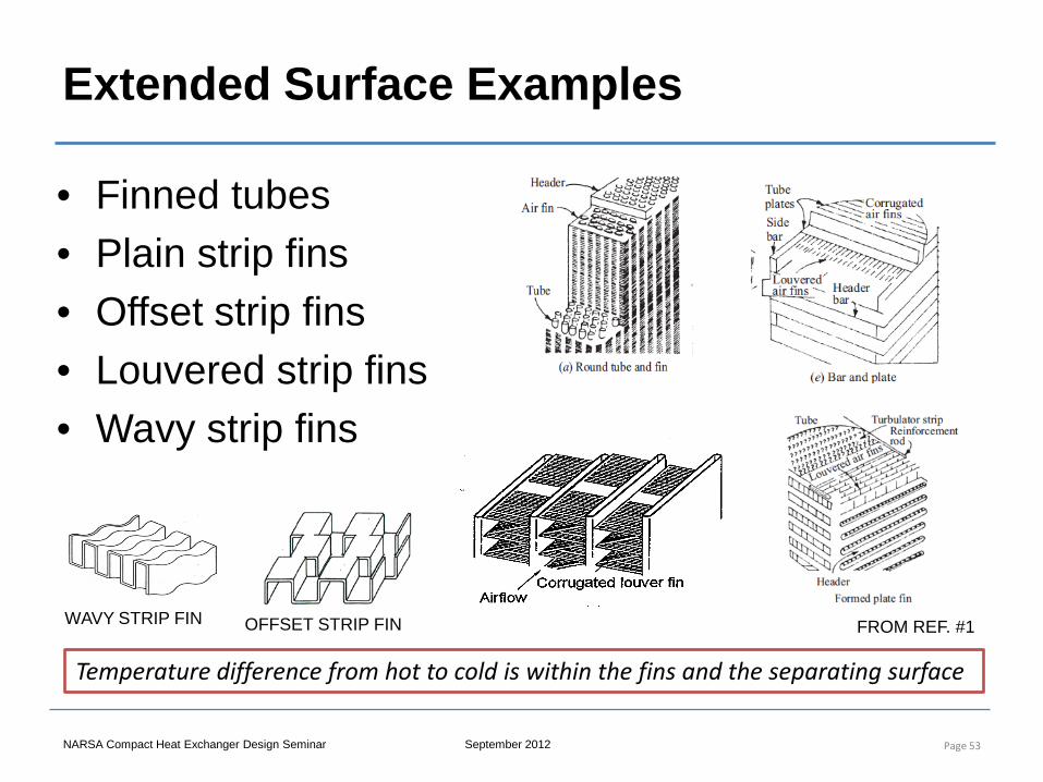
Extended Surface Examples
• Finned tubes • Plain strip fins • Offset strip fins • Louvered strip fins • Wavy strip fins
Page 53
Temperature difference from hot to cold is within the fins and the separating surface
OFFSET STRIP FIN WAVY STRIP FIN FROM REF. #1
NARSA Compact Heat Exchanger Design Seminar September 2012
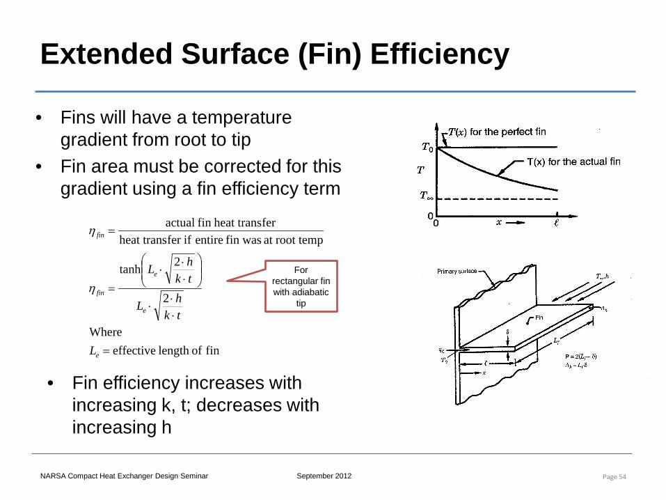
Extended Surface (Fin) Efficiency
• Fins will have a temperature gradient from root to tip
• Fin area must be corrected for this gradient using a fin efficiency term
Page 54
fin of length effectiveWhere
2
2tanh
root tempat wasfin entire iffer heat transferheat trans fin actual
=
⋅⋅⋅
⋅⋅⋅
=
=
e
e
e
fin
fin
L
tkhL
tkhL
η
η
• Fin efficiency increases with increasing k, t; decreases with increasing h
For rectangular fin with adiabatic
tip
NARSA Compact Heat Exchanger Design Seminar September 2012
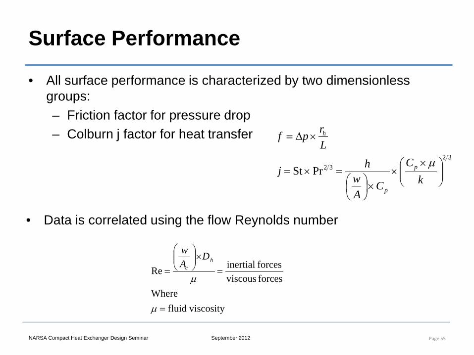
Surface Performance
• All surface performance is characterized by two dimensionless groups: – Friction factor for pressure drop – Colburn j factor for heat transfer
Page 55
3232PrSt
××
×
=×=
×∆=
kC
CAw
hj
Lrpf
p
p
h
µ
• Data is correlated using the flow Reynolds number
viscosityfluidWhere
forces viscousforces inertialRe
=
=×
=
µ
µ
hc
DAw
NARSA Compact Heat Exchanger Design Seminar September 2012
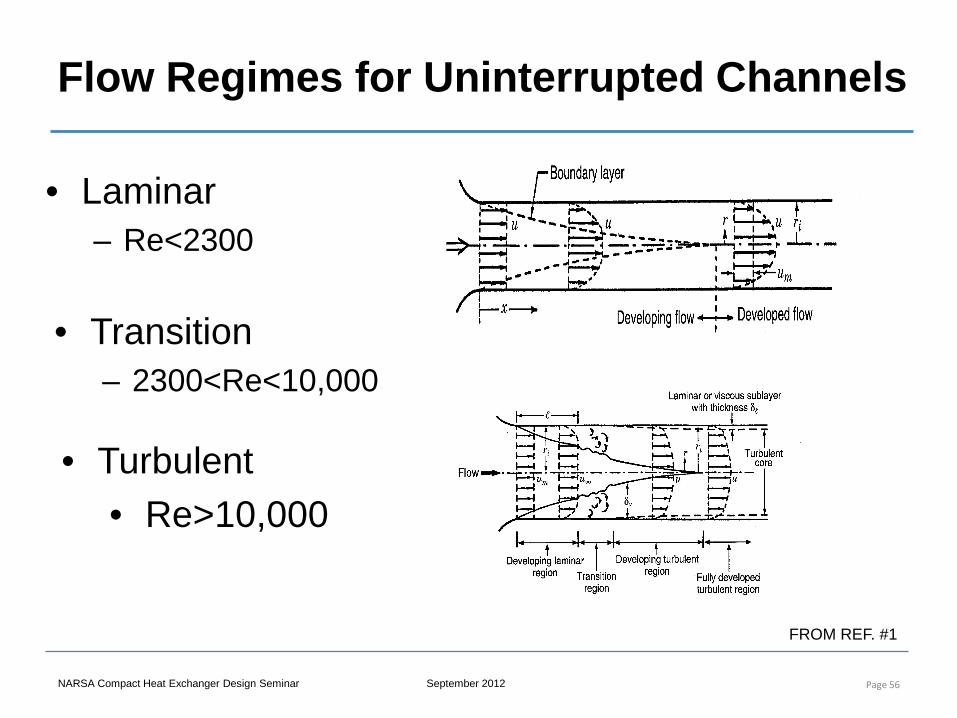
Flow Regimes for Uninterrupted Channels
• Laminar – Re<2300
Page 56
• Turbulent • Re>10,000
• Transition – 2300<Re<10,000
FROM REF. #1
NARSA Compact Heat Exchanger Design Seminar September 2012
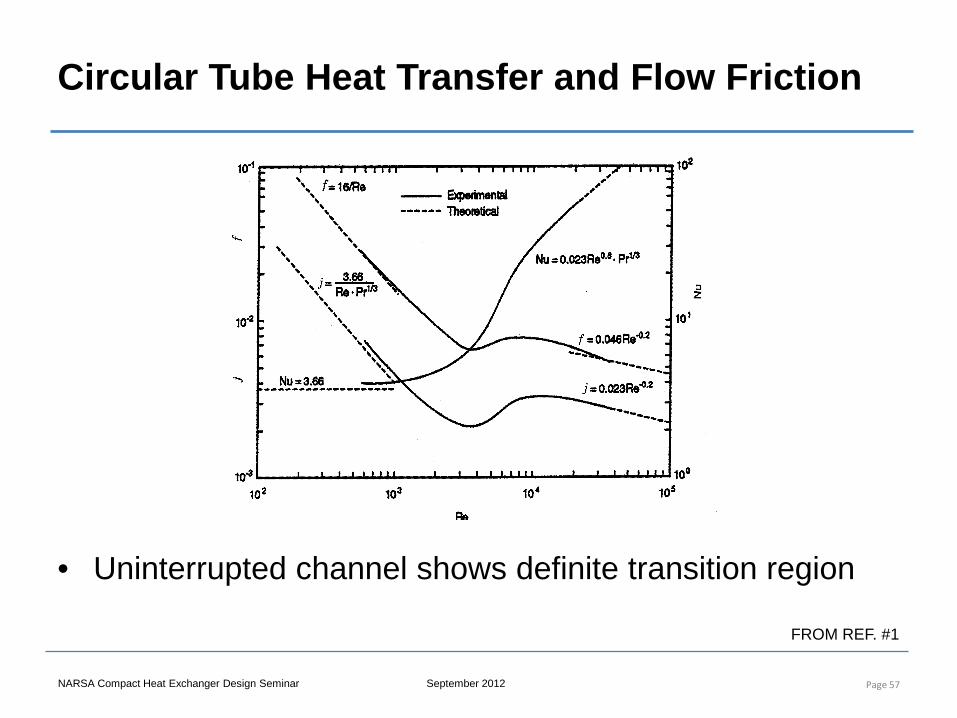
Circular Tube Heat Transfer and Flow Friction
• Uninterrupted channel shows definite transition region
Page 57
FROM REF. #1
NARSA Compact Heat Exchanger Design Seminar September 2012
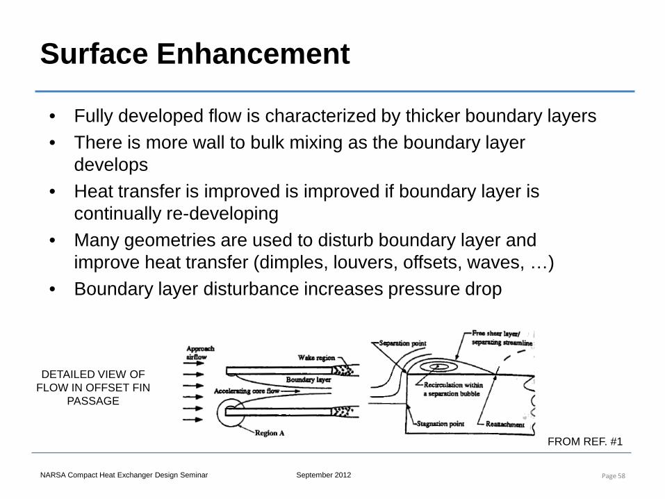
Surface Enhancement
Page 58
• Fully developed flow is characterized by thicker boundary layers • There is more wall to bulk mixing as the boundary layer
develops • Heat transfer is improved is improved if boundary layer is
continually re-developing • Many geometries are used to disturb boundary layer and
improve heat transfer (dimples, louvers, offsets, waves, …) • Boundary layer disturbance increases pressure drop
DETAILED VIEW OF FLOW IN OFFSET FIN
PASSAGE
FROM REF. #1
NARSA Compact Heat Exchanger Design Seminar September 2012
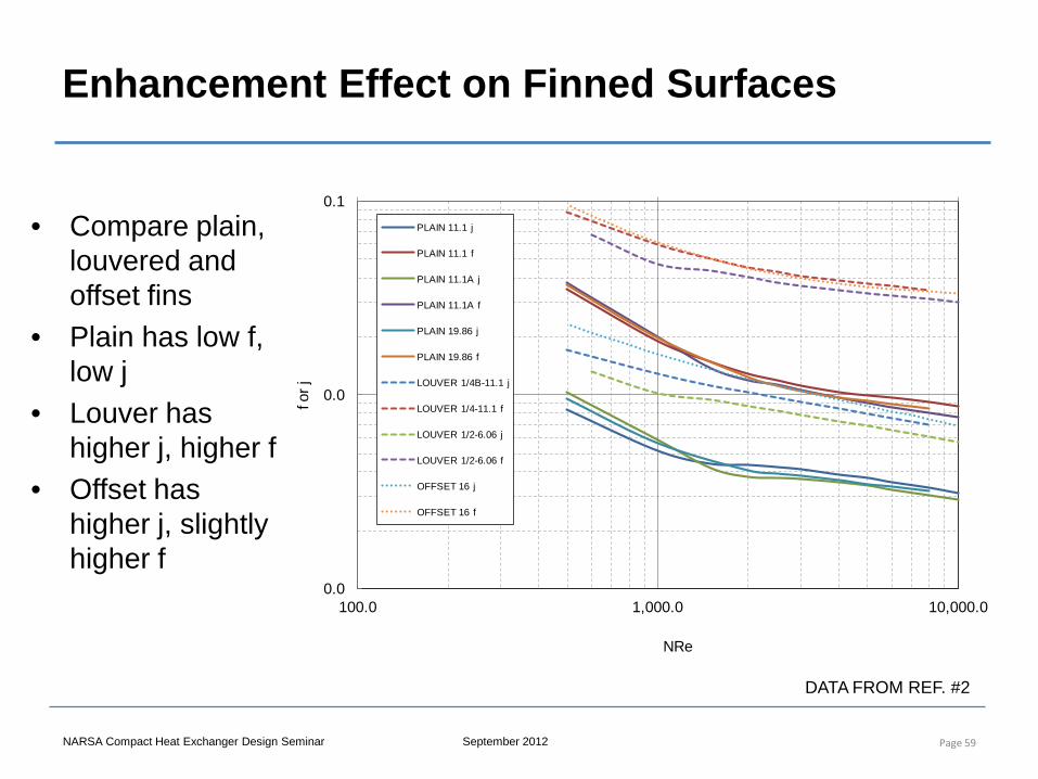
Enhancement Effect on Finned Surfaces
• Compare plain, louvered and offset fins
• Plain has low f, low j
• Louver has higher j, higher f
• Offset has higher j, slightly higher f
Page 59
0.0
0.0
0.1
100.0 1,000.0 10,000.0
f or j
NRe
PLAIN 11.1 j
PLAIN 11.1 f
PLAIN 11.1A j
PLAIN 11.1A f
PLAIN 19.86 j
PLAIN 19.86 f
LOUVER 1/4B-11.1 j
LOUVER 1/4-11.1 f
LOUVER 1/2-6.06 j
LOUVER 1/2-6.06 f
OFFSET 16 j
OFFSET 16 f
DATA FROM REF. #2
NARSA Compact Heat Exchanger Design Seminar September 2012
Fin Selection Example
• Size a tube and center heat exchanger for the following conditions: – 50 GPM of PGW enters at 225 F – Cooled by 400 lb/min of air entering at 120 F – Must cool PGW to 213.5 F (80 kW) – Allow 0.5 psid on liquid side, 1.5 in H2O on air side
• Size using the following surfaces: – Liquid side: plain flattened tube, finned flat tube – Air side: Plain fins (11 and 20 fins/in), Louvered fins (11 fins/in x
¼” spacing), offset fin (16 fins/in x 1/8” offset)
Page 60
NARSA Compact Heat Exchanger Design Seminar September 2012
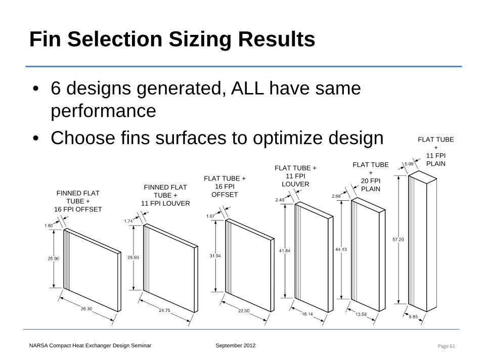
Fin Selection Sizing Results
• 6 designs generated, ALL have same performance
• Choose fins surfaces to optimize design
Page 61
FLAT TUBE +
11 FPI PLAIN FLAT TUBE
+ 20 FPI PLAIN
FLAT TUBE + 11 FPI
LOUVER FLAT TUBE +
16 FPI OFFSET
FINNED FLAT TUBE +
11 FPI LOUVER FINNED FLAT
TUBE + 16 FPI OFFSET
Compact Heat Exchanger Design, Characteristics and Trends
6. Engine Cooling Systems
NARSA Heavy Duty Heating and Cooling Conference Sept 2012 Ann Arbor, MI
Instructor: Joe Borghese
NARSA Compact Heat Exchanger Design Seminar September 2012
Objectives of Engine Cooling System
• Maintain the highest and most efficient operating temperature within the engine.
• Bring the engine up to the operating temperature as quickly as possible in order to reduce the wear on the engine components and increase the fuel economy.
Page 63
NARSA Compact Heat Exchanger Design Seminar September 2012
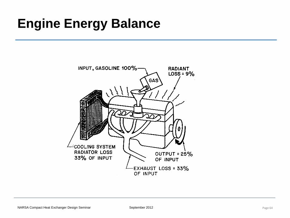
Engine Energy Balance
Page 64
NARSA Compact Heat Exchanger Design Seminar September 2012
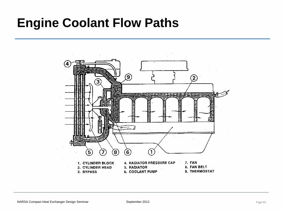
Engine Coolant Flow Paths
Page 65
NARSA Compact Heat Exchanger Design Seminar September 2012
Engine Operating Temperature
If the engine temperature is too high, various problems will occur: • Overheating of lubricating oil causing it to breakdown • Overheating of parts causing loss of strength • Reduced clearance between engine parts causing increase in friction and
resultant excessive wear.
Page 66
If the engine temperature is too low, various problems will occur: • Poor fuel mileage and power loss due to less efficient combustion process. • Increased carbon buildup due to condensation of the fuel and excessive
buildup on the intake valves. • Increased varnish and sludge buildup within the lubrication system due to
the cooler engine.
NARSA Compact Heat Exchanger Design Seminar September 2012
Sizing of Engine Cooling Components
• In order to design the engine cooling system, the following inputs are required: – Engine full load heat rejection to the coolant – Automatic transmission heat rejection to coolant – Engine oil cooler heat rejection to the coolant (if used) – Any other heat exchanger (e.g., condenser, intercooler, fuel cooler, etc.)
heat transfer performance and pressure drop characteristics – Coolant pump performance, coolant loop pressure drop and pump
power target – Fan performance and fan input power target – Ram airflow target and pressure drop from the air dam through the
underhood airflow system.
Page 67
NARSA Compact Heat Exchanger Design Seminar September 2012
Engine Coolant
• 50/50 mixture of ethylene glycol and water (EGW)
• The coolant provides protection against freezing (−34°F freezing point) and boiling (226°F boiling point at ambient pressure).
• Additives provide corrosion protection in the cooling system.
• Different specification coolants are used for aluminum versus cast iron engine and Cu-Br versus Al radiators.
Page 68
NARSA Compact Heat Exchanger Design Seminar September 2012
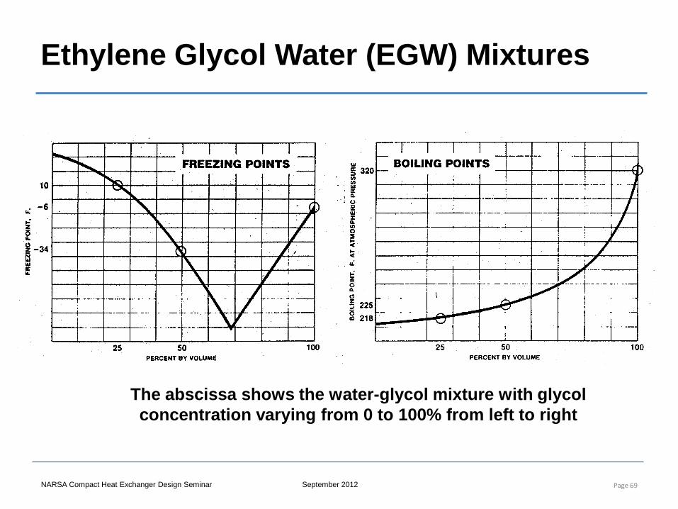
Ethylene Glycol Water (EGW) Mixtures
Page 69
The abscissa shows the water-glycol mixture with glycol concentration varying from 0 to 100% from left to right
NARSA Compact Heat Exchanger Design Seminar September 2012
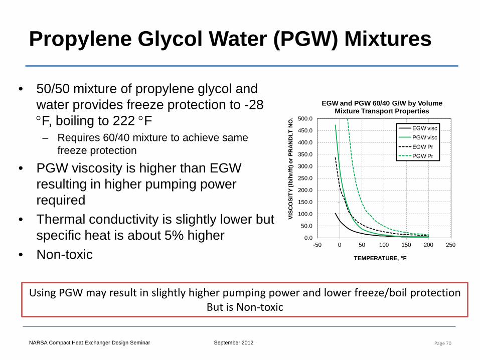
Propylene Glycol Water (PGW) Mixtures
• 50/50 mixture of propylene glycol and water provides freeze protection to -28 °F, boiling to 222 °F
– Requires 60/40 mixture to achieve same freeze protection
• PGW viscosity is higher than EGW resulting in higher pumping power required
• Thermal conductivity is slightly lower but specific heat is about 5% higher
• Non-toxic
Page 70
Using PGW may result in slightly higher pumping power and lower freeze/boil protection But is Non-toxic
0.0
50.0
100.0
150.0
200.0
250.0
300.0
350.0
400.0
450.0
500.0
-50 0 50 100 150 200 250
VISC
OSI
TY (l
b/hr
/ft) o
r PR
AN
DLT
NO
.
TEMPERATURE, °F
EGW and PGW 60/40 G/W by Volume Mixture Transport Properties
EGW viscPGW viscEGW PrPGW Pr
NARSA Compact Heat Exchanger Design Seminar September 2012
Air Flow Determination
• Driving forces – Ram air effect due to vehicle speed – Low pressure discharge areas (under vehicle) – Fans
• Flow resistances – Bumper, grille – Condenser, Radiator, Charge air cooler, oil coolers – Exit flow path(s) to ambient through engine compartment, upper
and lower exits
• Air flow is set where pressure drop through the resistances equals the pressure rise through the drivers
Page 71
NARSA Compact Heat Exchanger Design Seminar September 2012
Fan Drive Systems
Fan drive systems can be segmented into three types of fan drives for providing shaft power to the fan assembly.
– Engine Driven Fan Drives (up to 20+ kW) – Electric Motor Fan Drives (up to 3 kW) – Hydraulic Fluid Fan Drives (1.5 kW to 5 kW)
Page 72
NARSA Compact Heat Exchanger Design Seminar September 2012
Fan Drive Systems
• The engine driven fan drive is the traditional means of providing power to the fan. Some innovations over the years have occurred including viscous coupling of the fan to the drive belt, molded plastic fan versus the stamped-metal fan, and more recently a move toward controlling the fan clutch electronically.
• Electric fan drives are the most common due to the ease of application, flexibility in mounting configuration, and ease of control. Various configurations have been applied with each having their particular benefits.
• Hydraulic fluid fan drive system consists of a hydraulic pump running off the engine that provides fluid power to a hydraulic motor that drives the fan(s). The advantage of this fan drive is the amount of power that can be delivered to a remotely mounted fan, 2.5 kW or more. This type of fan drive has been applied to some off highway vehicles
Page 73
NARSA Compact Heat Exchanger Design Seminar September 2012
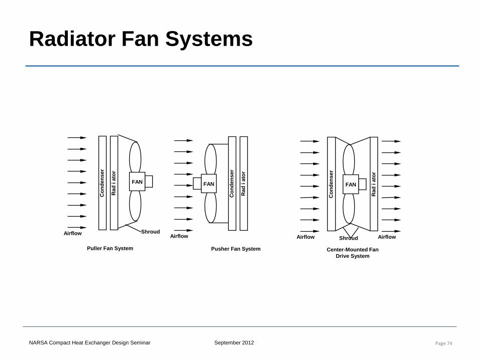
Radiator Fan Systems
Page 74
Rad
i at
or
Con
dens
er
Puller Fan System
FAN
Shroud Airflow
Rad
i at
or
Con
dens
er
FAN
Center-Mounted Fan Drive System
Shroud Airflow Airflow R
ad i
ator
Con
dens
er
Pusher Fan System
FAN
Airflow
NARSA Compact Heat Exchanger Design Seminar September 2012
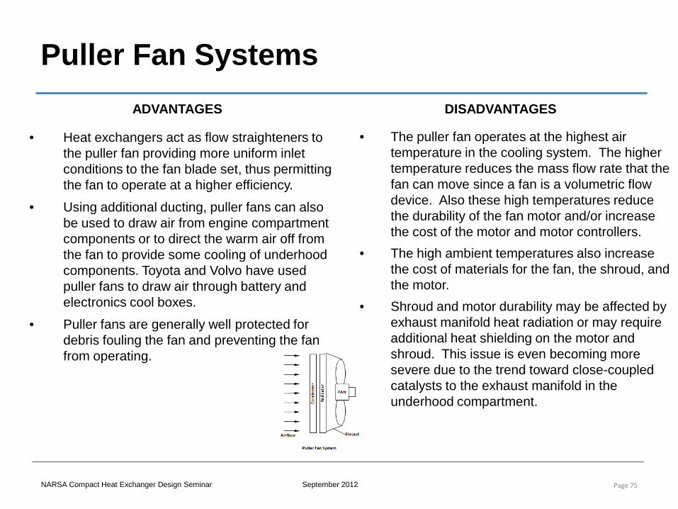
Puller Fan Systems
• Heat exchangers act as flow straighteners to the puller fan providing more uniform inlet conditions to the fan blade set, thus permitting the fan to operate at a higher efficiency.
• Using additional ducting, puller fans can also be used to draw air from engine compartment components or to direct the warm air off from the fan to provide some cooling of underhood components. Toyota and Volvo have used puller fans to draw air through battery and electronics cool boxes.
• Puller fans are generally well protected for debris fouling the fan and preventing the fan from operating.
Page 75
• The puller fan operates at the highest air temperature in the cooling system. The higher temperature reduces the mass flow rate that the fan can move since a fan is a volumetric flow device. Also these high temperatures reduce the durability of the fan motor and/or increase the cost of the motor and motor controllers.
• The high ambient temperatures also increase the cost of materials for the fan, the shroud, and the motor.
• Shroud and motor durability may be affected by exhaust manifold heat radiation or may require additional heat shielding on the motor and shroud. This issue is even becoming more severe due to the trend toward close-coupled catalysts to the exhaust manifold in the underhood compartment.
ADVANTAGES DISADVANTAGES
NARSA Compact Heat Exchanger Design Seminar September 2012
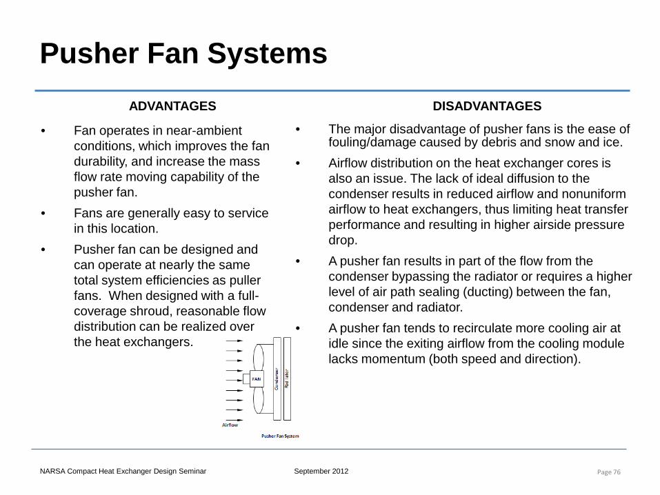
Pusher Fan Systems
• Fan operates in near-ambient conditions, which improves the fan durability, and increase the mass flow rate moving capability of the pusher fan.
• Fans are generally easy to service in this location.
• Pusher fan can be designed and can operate at nearly the same total system efficiencies as puller fans. When designed with a full-coverage shroud, reasonable flow distribution can be realized over the heat exchangers.
Page 76
• The major disadvantage of pusher fans is the ease of fouling/damage caused by debris and snow and ice.
• Airflow distribution on the heat exchanger cores is also an issue. The lack of ideal diffusion to the condenser results in reduced airflow and nonuniform airflow to heat exchangers, thus limiting heat transfer performance and resulting in higher airside pressure drop.
• A pusher fan results in part of the flow from the condenser bypassing the radiator or requires a higher level of air path sealing (ducting) between the fan, condenser and radiator.
• A pusher fan tends to recirculate more cooling air at idle since the exiting airflow from the cooling module lacks momentum (both speed and direction).
ADVANTAGES DISADVANTAGES
NARSA Compact Heat Exchanger Design Seminar September 2012
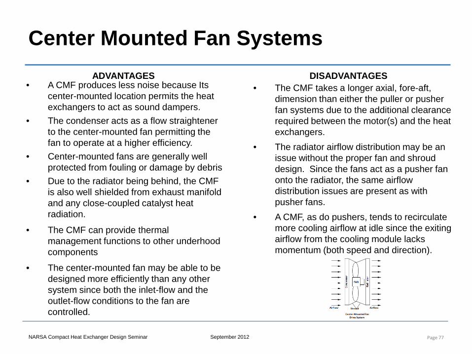
Center Mounted Fan Systems
• A CMF produces less noise because Its center-mounted location permits the heat exchangers to act as sound dampers.
• The condenser acts as a flow straightener to the center-mounted fan permitting the fan to operate at a higher efficiency.
• Center-mounted fans are generally well protected from fouling or damage by debris
• Due to the radiator being behind, the CMF is also well shielded from exhaust manifold and any close-coupled catalyst heat radiation.
• The CMF can provide thermal management functions to other underhood components
• The center-mounted fan may be able to be designed more efficiently than any other system since both the inlet-flow and the outlet-flow conditions to the fan are controlled.
Page 77
• The CMF takes a longer axial, fore-aft, dimension than either the puller or pusher fan systems due to the additional clearance required between the motor(s) and the heat exchangers.
• The radiator airflow distribution may be an issue without the proper fan and shroud design. Since the fans act as a pusher fan onto the radiator, the same airflow distribution issues are present as with pusher fans.
• A CMF, as do pushers, tends to recirculate more cooling airflow at idle since the exiting airflow from the cooling module lacks momentum (both speed and direction).
ADVANTAGES DISADVANTAGES

NARSA Compact Heat Exchanger Design Seminar September 2012
Electric Assist Pusher Fans
Electric Assist Pusher Fan
• A single or dual electric pusher fan(s) can be added to assist the engine driven fan system at low vehicle speeds and severe ambient conditions.
• These fans have generally lower power levels than an all-electric cooling system.
• The amount of idle airflow recirculation can be increased (or at least not improved) when this fan type is applied to a vehicle.
Applications
• Current applications include both cars and trucks where additional cooling is required. Motor applications include both the standard brush type and a brushless DC motors
Page 78
Rad
i at
or
Con
dens
er
Assist Pusher Fan System
FAN
Eng Fan
NARSA Compact Heat Exchanger Design Seminar September 2012
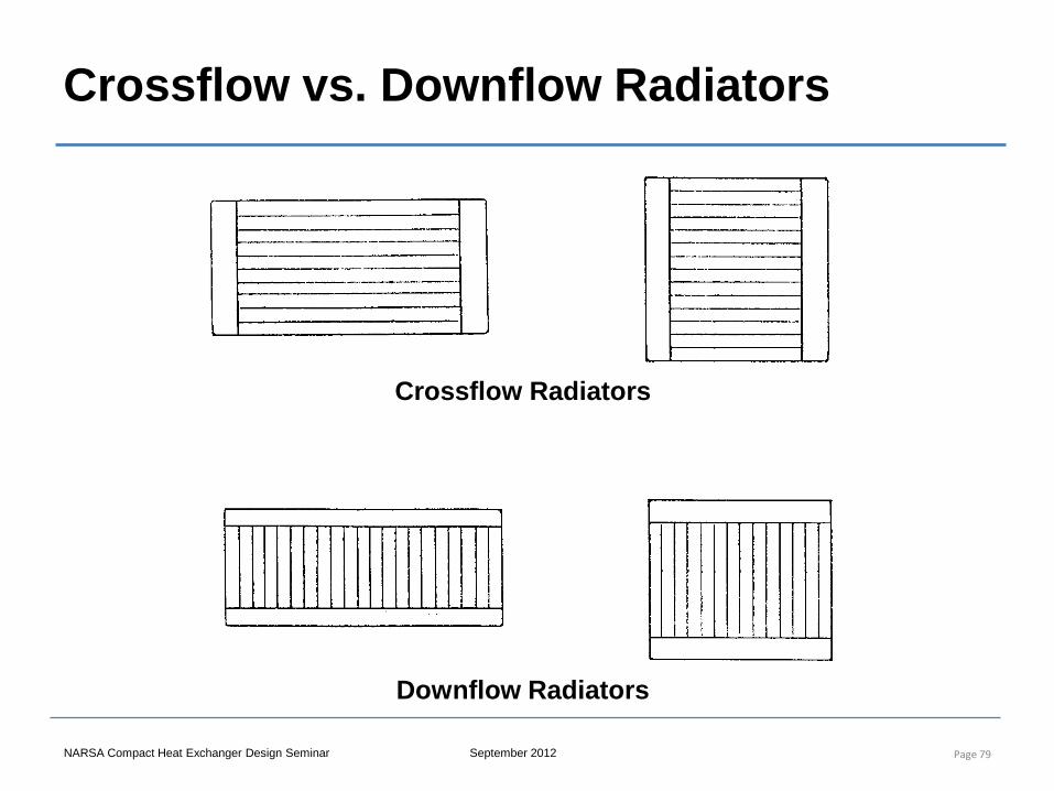
Crossflow vs. Downflow Radiators
Page 79
Crossflow Radiators
Downflow Radiators
NARSA Compact Heat Exchanger Design Seminar September 2012
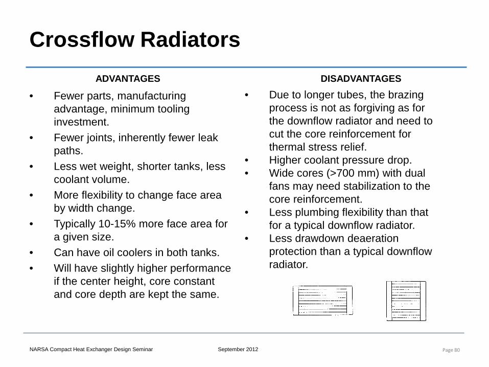
Crossflow Radiators
• Fewer parts, manufacturing advantage, minimum tooling investment.
• Fewer joints, inherently fewer leak paths.
• Less wet weight, shorter tanks, less coolant volume.
• More flexibility to change face area by width change.
• Typically 10-15% more face area for a given size.
• Can have oil coolers in both tanks. • Will have slightly higher performance
if the center height, core constant and core depth are kept the same.
Page 80
• Due to longer tubes, the brazing process is not as forgiving as for the downflow radiator and need to cut the core reinforcement for thermal stress relief.
• Higher coolant pressure drop. • Wide cores (>700 mm) with dual
fans may need stabilization to the core reinforcement.
• Less plumbing flexibility than that for a typical downflow radiator.
• Less drawdown deaeration protection than a typical downflow radiator.
ADVANTAGES DISADVANTAGES
NARSA Compact Heat Exchanger Design Seminar September 2012
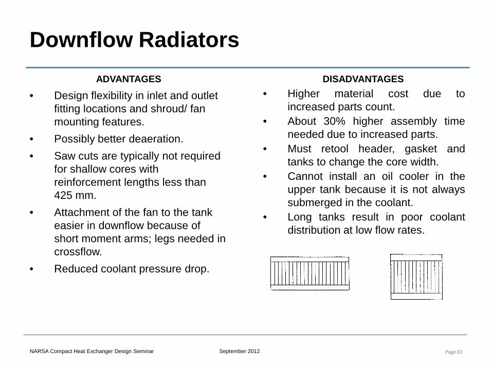
Downflow Radiators
• Design flexibility in inlet and outlet fitting locations and shroud/ fan mounting features.
• Possibly better deaeration. • Saw cuts are typically not required
for shallow cores with reinforcement lengths less than 425 mm.
• Attachment of the fan to the tank easier in downflow because of short moment arms; legs needed in crossflow.
• Reduced coolant pressure drop.
Page 81
• Higher material cost due to increased parts count.
• About 30% higher assembly time needed due to increased parts.
• Must retool header, gasket and tanks to change the core width.
• Cannot install an oil cooler in the upper tank because it is not always submerged in the coolant.
• Long tanks result in poor coolant distribution at low flow rates.
ADVANTAGES DISADVANTAGES
NARSA Compact Heat Exchanger Design Seminar September 2012
Oil Coolers
• Oil coolers used to maintain desired oil temperatures – Gasoline engine oil sump ~285F – Diesel engine oil sump ~265F – Transmission oil ~285F
• Common to have transmission oil coolers in radiator tank • Air-oil coolers may be added for transmission, power
steering and engine oil • Low duty coolers may be plain or finned tubes • Higher performance coolers will use louvered fins in bar-
plate or tube-center configuration
Page 82
NARSA Compact Heat Exchanger Design Seminar September 2012
Charge Air Coolers
Page 83
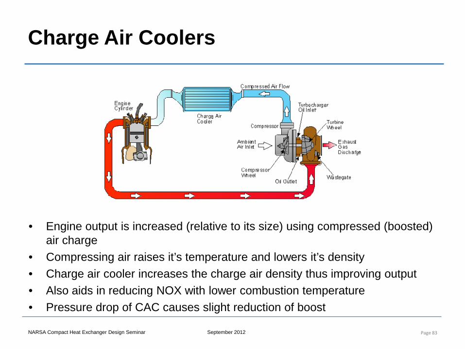
• Engine output is increased (relative to its size) using compressed (boosted) air charge
• Compressing air raises it’s temperature and lowers it’s density • Charge air cooler increases the charge air density thus improving output • Also aids in reducing NOX with lower combustion temperature • Pressure drop of CAC causes slight reduction of boost
NARSA Compact Heat Exchanger Design Seminar September 2012
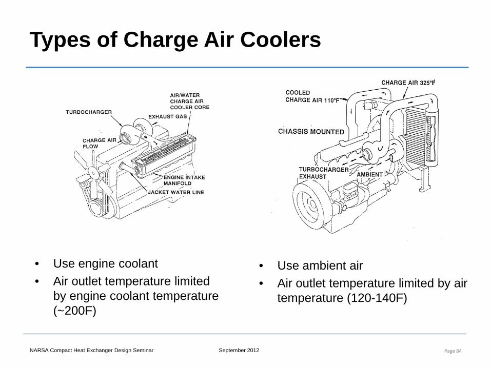
Types of Charge Air Coolers
Page 84
• Use engine coolant • Air outlet temperature limited
by engine coolant temperature (~200F)
• Use ambient air • Air outlet temperature limited by air
temperature (120-140F)
NARSA Compact Heat Exchanger Design Seminar September 2012
Manifold Design in Air to Air Charge Air Coolers
• Manifold (tank) design is not as critical in coolant or oil manifolds because velocity pressure is low in most liquid applications
• If liquid tanks are large enough the static pressure change in the tank is minimal and the flow will distribute evenly
• For air flowing in compact manifolds, the static pressure change in the manifolds may give rise to non-uniform flow distribution and negatively impact performance
Page 85
NARSA Compact Heat Exchanger Design Seminar September 2012
Manifold Performance
Page 86
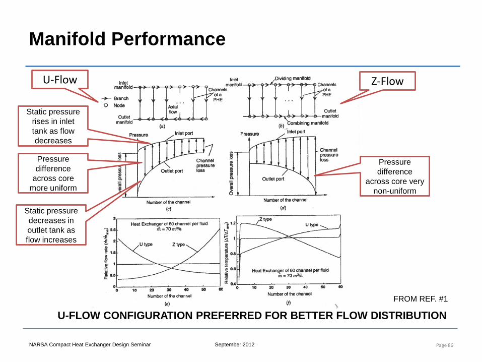
U-Flow
Static pressure rises in inlet tank as flow decreases
Static pressure decreases in outlet tank as flow increases
Pressure difference
across core more uniform
Z-Flow
Pressure difference
across core very non-uniform
U-FLOW CONFIGURATION PREFERRED FOR BETTER FLOW DISTRIBUTION FROM REF. #1
NARSA Compact Heat Exchanger Design Seminar September 2012
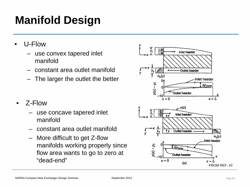
Manifold Design
• U-Flow – use convex tapered inlet
manifold – constant area outlet manifold – The larger the outlet the better
Page 87
• Z-Flow – use concave tapered inlet
manifold – constant area outlet manifold – More difficult to get Z-flow
manifolds working properly since flow area wants to go to zero at “dead-end”
FROM REF. #2
Compact Heat Exchanger Design, Characteristics and Trends
7. Auto Air Conditioning Systems
NARSA Heavy Duty Heating and Cooling Conference Sept 2012 Ann Arbor, MI
Instructor: Joe Borghese
NARSA Compact Heat Exchanger Design Seminar September 2012
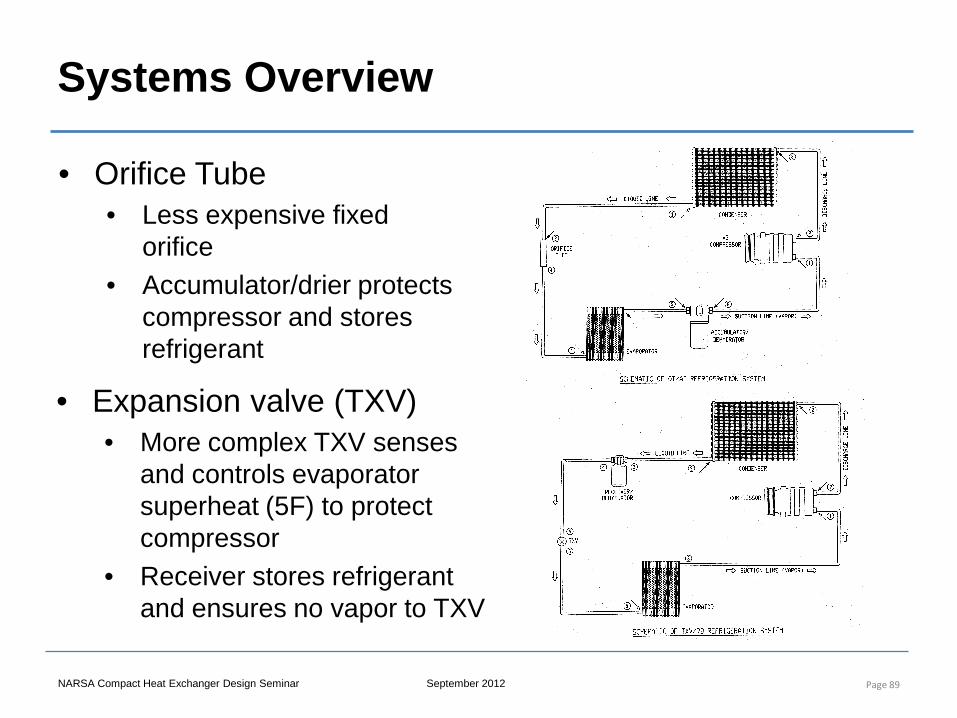
Systems Overview
Page 89
• Orifice Tube • Less expensive fixed
orifice • Accumulator/drier protects
compressor and stores refrigerant
• Expansion valve (TXV) • More complex TXV senses
and controls evaporator superheat (5F) to protect compressor
• Receiver stores refrigerant and ensures no vapor to TXV
NARSA Compact Heat Exchanger Design Seminar September 2012
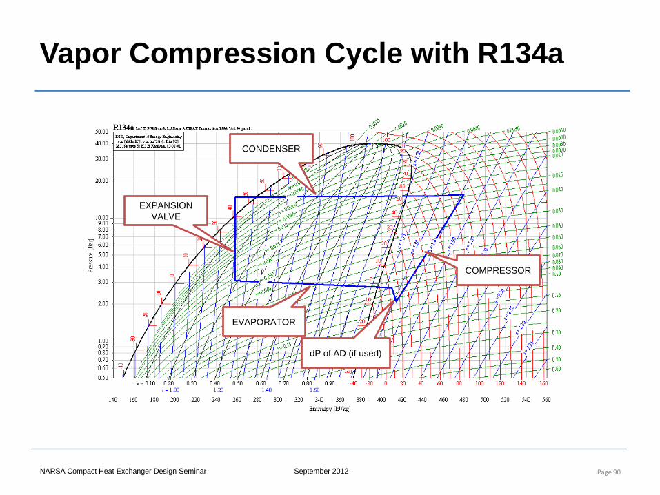
Vapor Compression Cycle with R134a
Page 90
COMPRESSOR
CONDENSER
EXPANSION VALVE
EVAPORATOR
dP of AD (if used)
NARSA Compact Heat Exchanger Design Seminar September 2012
Condenser Heat Exchanger
• Rejects refrigeration system heat to air • Total heat rejection = evaporator heat (~60%) plus
compressor work (~40%) • Condenser adds heat load and air pressure loss to
engine cooling heat exchanger • Due to R134a system pressure levels want the
condenser at the coolest location in the air heat sink • Reduce size by optimizing air side surface
– Condensing heat transfer coefficients can be 25 times air side
• Low refrigerant pressure drop maintains air-refrigerant temperature difference
Page 91
NARSA Compact Heat Exchanger Design Seminar September 2012
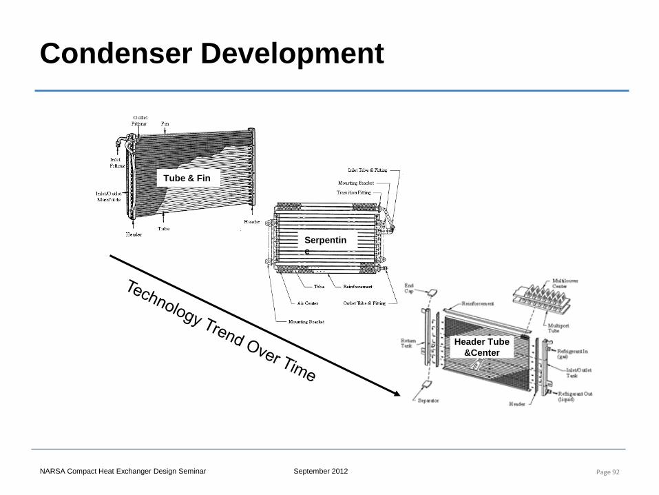
Condenser Development
Page 92
Tube & Fin
Serpentine
Header Tube &Center
NARSA Compact Heat Exchanger Design Seminar September 2012
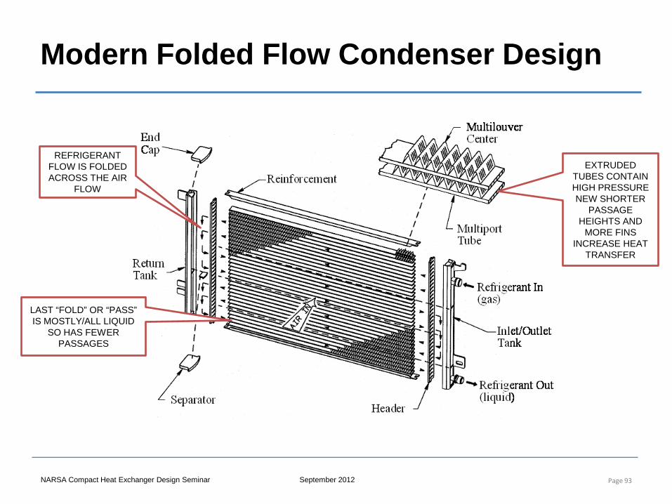
Modern Folded Flow Condenser Design
Page 93
REFRIGERANT FLOW IS FOLDED ACROSS THE AIR
FLOW
LAST “FOLD” OR “PASS” IS MOSTLY/ALL LIQUID
SO HAS FEWER PASSAGES
EXTRUDED TUBES CONTAIN HIGH PRESSURE NEW SHORTER
PASSAGE HEIGHTS AND
MORE FINS INCREASE HEAT
TRANSFER
Compact Heat Exchanger Design, Characteristics and Trends
8. Recent Developments and
Concluding Remarks
NARSA Heavy Duty Heating and Cooling Conference Sept 2012 Ann Arbor, MI
Instructor: Joe Borghese
NARSA Compact Heat Exchanger Design Seminar September 2012
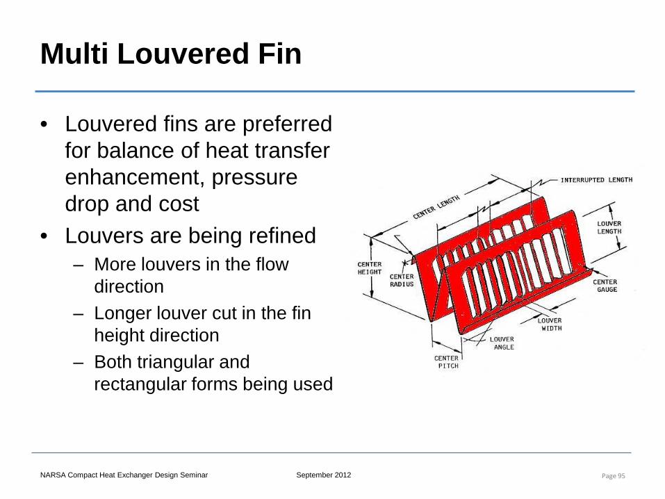
Multi Louvered Fin
Page 95
• Louvered fins are preferred for balance of heat transfer enhancement, pressure drop and cost
• Louvers are being refined – More louvers in the flow
direction – Longer louver cut in the fin
height direction – Both triangular and
rectangular forms being used
NARSA Compact Heat Exchanger Design Seminar September 2012
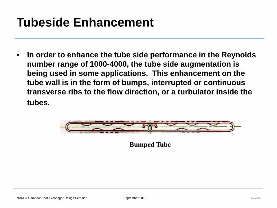
Tubeside Enhancement
• In order to enhance the tube side performance in the Reynolds number range of 1000-4000, the tube side augmentation is being used in some applications. This enhancement on the tube wall is in the form of bumps, interrupted or continuous transverse ribs to the flow direction, or a turbulator inside the tubes.
Page 96
Bumped Tube
NARSA Compact Heat Exchanger Design Seminar September 2012
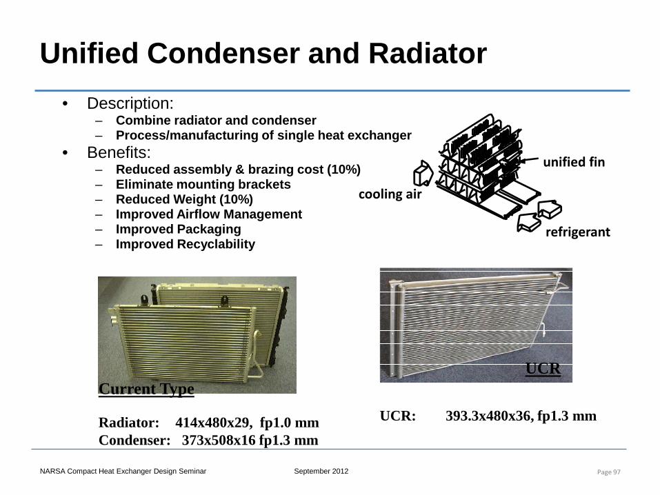
Unified Condenser and Radiator
Page 97
Current Type UCR
Radiator: 414x480x29, fp1.0 mm Condenser: 373x508x16 fp1.3 mm
UCR: 393.3x480x36, fp1.3 mm
refrigerant
unified fin
cooling air
• Description: – Combine radiator and condenser – Process/manufacturing of single heat exchanger
• Benefits: – Reduced assembly & brazing cost (10%) – Eliminate mounting brackets – Reduced Weight (10%) – Improved Airflow Management – Improved Packaging – Improved Recyclability
NARSA Compact Heat Exchanger Design Seminar September 2012
Advanced Systems
• Hybrid gas/electric systems require power electronics cooling – Inverter coolant loops added – Offset by smaller gas engine radiator
• Fuel cell systems require fuel cell stack and power electronics cooling
• Advanced gas engine systems will put thermostat under control of engine control unit
• Thermal storage heat exchangers being considered for reduced start up emissions
Page 98
NARSA Compact Heat Exchanger Design Seminar September 2012
Systems Consideration in Design
• Combination of engine, A/C, electronics, charge air, transmission, oil cooling along with vehicle aerodynamics and air fans require a SYSTEM approach to component design
• Accurate component models within high level system model are required in order to trade heat exchanger packaging, NTU, and pressure drop with air flow system
Page 99
NARSA Compact Heat Exchanger Design Seminar September 2012
Concluding Remarks
• Current and advanced automotive systems will continue to require cooling
• High performance, compact heat exchangers can be optimized given a range of well designed heat transfer surfaces
• The greatest gains in weight or size savings can be made when considering all cooling requirements in a thermal management system
Page 100


