19
COMPACT PROPULSION CONCEPTS FOR DOUBLE ENDED FERRIES Roland Schwandt, Vancouver, CA, CFOA September 2015

COMPACT PROPULSION CONCEPTS
FOR DOUBLE ENDED FERRIES
Roland Schwandt, Vancouver, CA, CFOA September 2015
YOUR PROPULSION EXPERTS
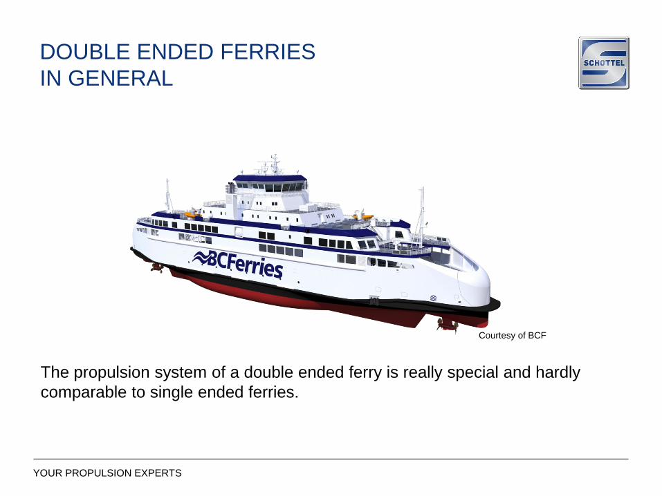
DOUBLE ENDED FERRIES
IN GENERAL
The propulsion system of a double ended ferry is really special and hardly
comparable to single ended ferries.
Courtesy of BCF
YOUR PROPULSION EXPERTS
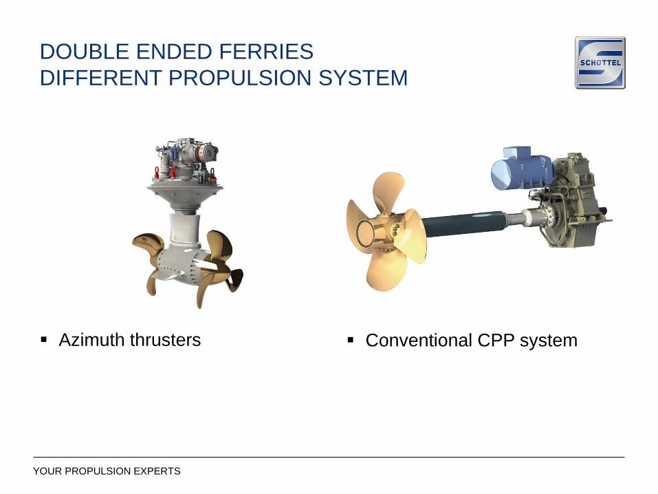
DOUBLE ENDED FERRIES
DIFFERENT PROPULSION SYSTEM
Conventional CPP system Azimuth thrusters

YOUR PROPULSION EXPERTS
DOUBLE ENDED FERRIES
AZIMUTHING THRUSTERS ADVANTAGES
• Higher maneuverability, even at
zero speed
• Easy maintenance, can be
exchanged even afloat
• Twin propeller systems are
available
• No rudders or separate
gearboxes are necessary
• Less space consuming
+
YOUR PROPULSION EXPERTS
DOUBLE ENDED FERRIES
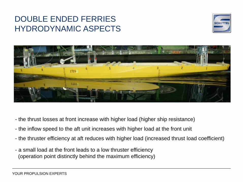
HYDRODYNAMIC ASPECTS
- the thrust losses at front increase with higher load (higher ship resistance)
- the thruster efficiency at aft reduces with higher load (increased thrust load coefficient)
- a small load at the front leads to a low thruster efficiency
(operation point distinctly behind the maximum efficiency)
- the inflow speed to the aft unit increases with higher load at the front unit
YOUR PROPULSION EXPERTS
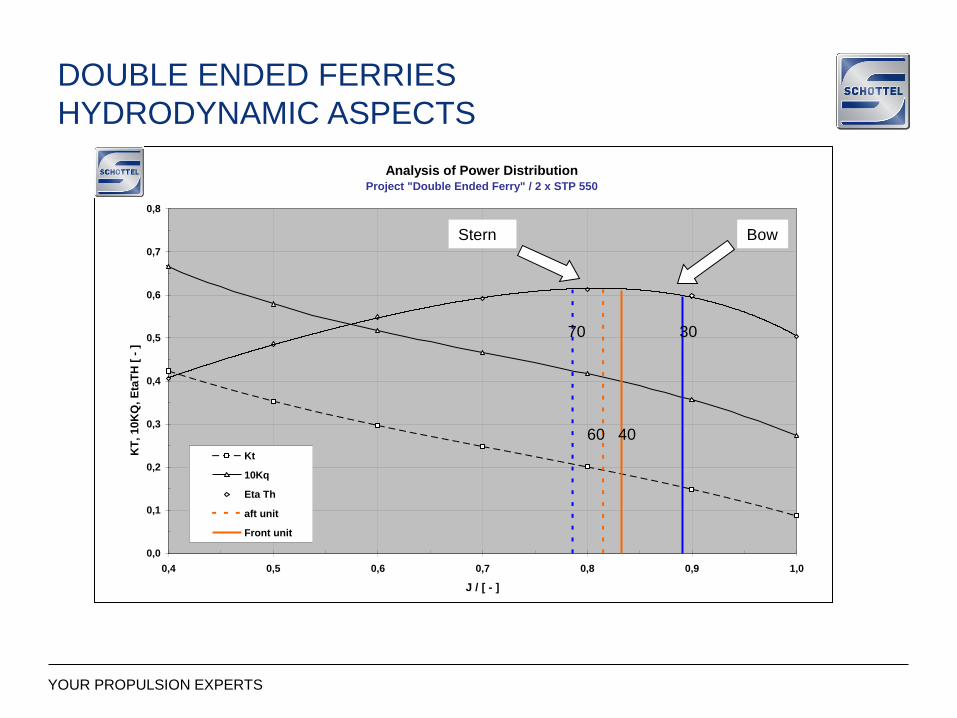
DOUBLE ENDED FERRIES
HYDRODYNAMIC ASPECTS
Analysis of Power DistributionProject "Double Ended Ferry" / 2 x STP 550
0,0
0,1
0,2
0,3
0,4
0,5
0,6
0,7
0,8
0,4 0,5 0,6 0,7 0,8 0,9 1,0
J / [ - ]
KT
, 1
0K
Q,
Eta
TH
[ -
] r
rrrr
rrr
Kt
10Kq
Eta Th
aft unit
Front unit
60 40
70 30
Stern Bow
YOUR PROPULSION EXPERTS
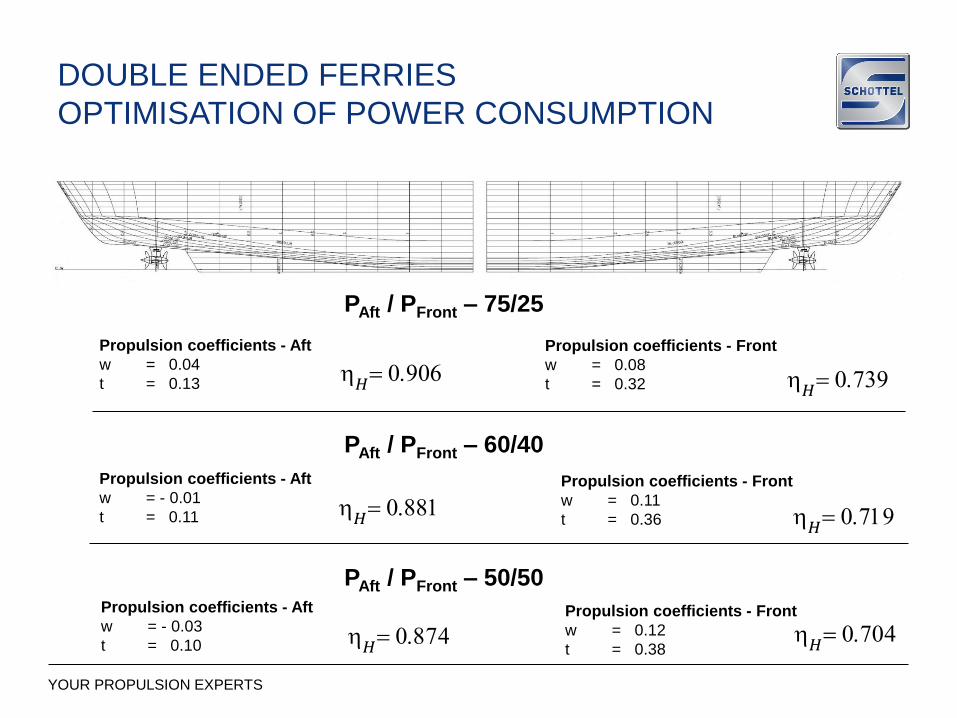
Propulsion coefficients - Aft
w = 0.04
t = 0.13
Propulsion coefficients - Front
w = 0.08
t = 0.32
PAft / PFront – 75/25
PAft / PFront – 60/40
Propulsion coefficients - Aft
w = - 0.01
t = 0.11
Propulsion coefficients - Front
w = 0.11
t = 0.36
PAft / PFront – 50/50Propulsion coefficients - Aft
w = - 0.03
t = 0.10
Propulsion coefficients - Front
w = 0.12
t = 0.38
h𝐻
= 0.906
h𝐻= 0.874
h𝐻= 0.719
h𝐻= 0.739
h𝐻= 0.881
h𝐻= 0.704
DOUBLE ENDED FERRIES
OPTIMISATION OF POWER CONSUMPTION

YOUR PROPULSION EXPERTS
DOUBLE ENDED FERRIES
OPTIMISATION OF POWER CONSUMPTION
50 60 70 80 90 100
0
200
400
600
800
1000
1200
1400
1600
1800
2000
2200
2400
Ptotal, 15 kts
Ptotal, 14 kts
Ptotal, 13 kts
Ptotal, 12 kts
Ptotal, 11 kts
SW-TFI
10-05-98
S. Kaul
Figure 11
Data-File: Symp-003.DAT
Graf-File: Symp-004.LPDPower Distribution: P total = f(VS, Distribution)
Ptotal / [kW]
Paft / P total / [%]
Pfore / P total / [%]
50 30 1040 20 0
2 x 1200kW
2 x 2050 kW2 x STP 1010
2.1m Prop dia
2 x STP 1515
2.5m Prop dia

YOUR PROPULSION EXPERTS
DOUBLE ENDED FERRIES
OPTIMISATION OF POWER CONSUMPTION
Installation with 4 units
the optimum power distribution
between front and aft unit is
usually in the range between
50 / 50 and 60 / 40 with
respect to total power
Installation with 2 units
the optimum power distribution between front and aft unit is usually in the range between 70 / 30 and 85 / 15 with respect to total power
An optimised installation configuration reduces the power consumption especially for 2 units
4 x STP 1515 2 x STP 1515

YOUR PROPULSION EXPERTS
DOUBLE ENDED FERRIES
DIESEL DIRECT OR DIESEL ELECTRIC

YOUR PROPULSION EXPERTS
DOUBLE ENDED FERRIES
DIESEL DIRECT OR DIESEL ELECTRIC
Diesel direct
Lower CAPEX
Sophisticated long shaft line
Distinct engine position
Higher emission since bow unit
is very often operated in low
load mode
Diesel electric
Higher CAPEX
Simple and short shaft line
High flexibility with regards to
the genset position
Less emissions since genset
always operates at the optimum
rpm
step less speed variation of
prime mover till lowest rpm
values (high maneuverability)
Conversion losses approx. 12%
YOUR PROPULSION EXPERTS
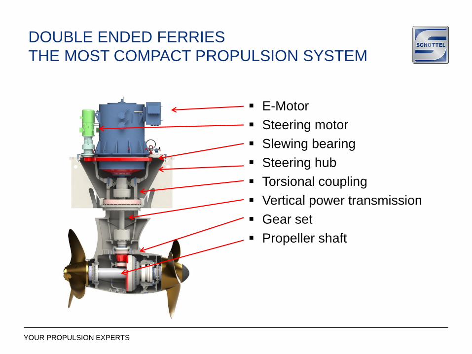
DOUBLE ENDED FERRIES
THE MOST COMPACT PROPULSION SYSTEM
E-Motor
Steering motor
Slewing bearing
Steering hub
Torsional coupling
Vertical power transmission
Gear set
Propeller shaft

YOUR PROPULSION EXPERTS
COMBI DRIVE VS Z-DRIVE
YOUR PROPULSION EXPERTS
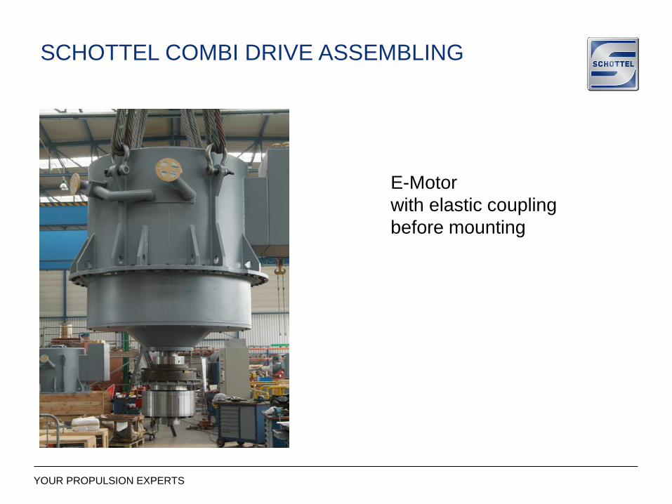
E-Motor
with elastic coupling
before mounting
SCHOTTEL COMBI DRIVE ASSEMBLING

YOUR PROPULSION EXPERTS
SCHOTTEL COMBI DRIVE ASSEMBLING
YOUR PROPULSION EXPERTS
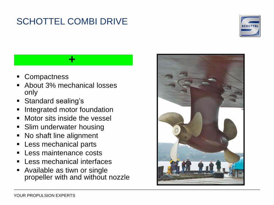
+
SCHOTTEL COMBI DRIVE
Compactness
About 3% mechanical losses only
Standard sealing’s
Integrated motor foundation
Motor sits inside the vessel
Slim underwater housing
No shaft line alignment
Less mechanical parts
Less maintenance costs
Less mechanical interfaces
Available as tiwn or singlepropeller with and without nozzle
YOUR PROPULSION EXPERTS 17
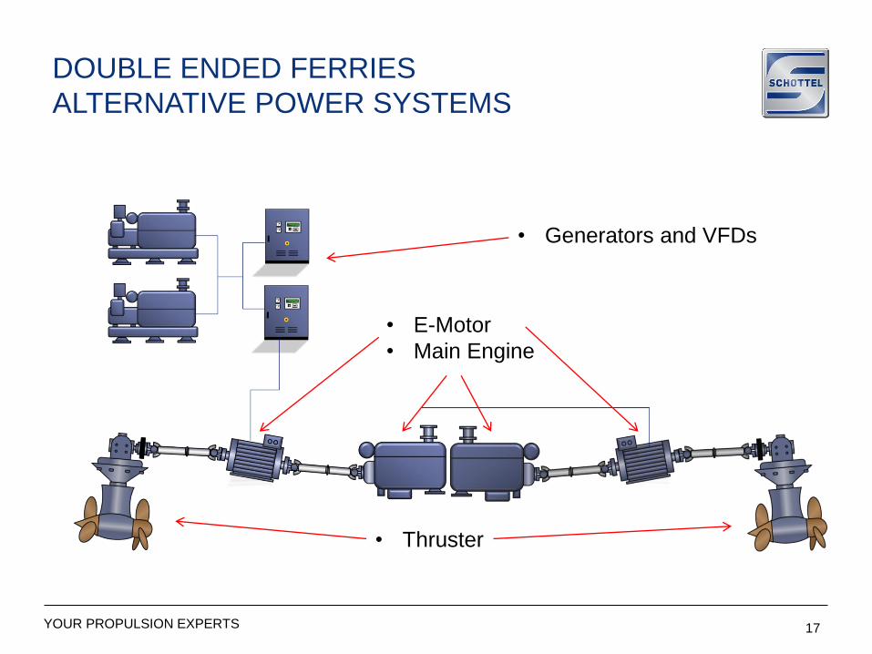
• Generators and VFDs
• E-Motor
• Main Engine
• Thruster
DOUBLE ENDED FERRIES
ALTERNATIVE POWER SYSTEMS
YOUR PROPULSION EXPERTS
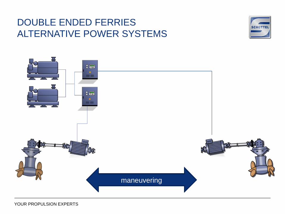
DOUBLE ENDED FERRIES
ALTERNATIVE POWER SYSTEMS
Sailing directionmaneuvering

YOUR PROPULSION EXPERTS
THANK YOU FOR YOUR KIND ATTENTION


