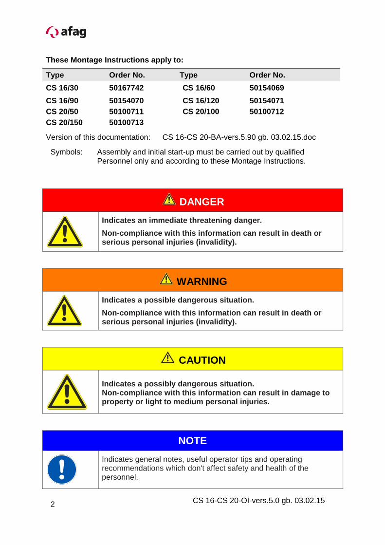
Version of this documentation: CS 16-CS 20-BA-vers.5.90 gb. 03.02.15.doc
DANGER
Indicates an immediate threatening danger.
Non-compliance with this information can result in death or serious personal injuries (invalidity).
WARNING
Indicates a possible dangerous situation.
Non-compliance with this information can result in death or serious personal injuries (invalidity).
CAUTION
Indicates a possibly dangerous situation. Non-compliance with this information can result in damage to property or light to medium personal injuries.
NOTE
Indicates general notes, useful operator tips and operating recommendations which don't affect safety and health of the personnel.
Symbols: Assembly and initial start-up must be carried out by qualified Personnel only and according to these Montage Instructions.
2
Table of Contents:
1.0.0 Declaration Incorporation Page 5
1.1.0 Declaration Incorporation according to the Machinery Directive
2006/42/EC Page 5
2.0.0 Module Information Page 6
2.1.0 Transport and storage (packing and unpacking) Page 6
2.1.1 Possibilites of fastening Page 7
2.1.2 Centering bushings and hole matrix Page 8
2.1.3 Tightening torques for screws Page 9
2.1.4 Slides unit load factors CS 16 Page 10
2.1.5 Preferred combinations CS 16 Page 11
2.1.6 Slides unit load factors CS 20 Page 12
2.1.7 Preferred combinations CS 20 Page 13
3.0.0 Montage Instructions Page 14
3.1.0 Manufacturer address Page 14
3.1.1 Symbols Page 15
3.1.2 General description Page 15
3.1.3 Description of the module Page 16
3.1.4 Scope of supply Page 17
3.1.5 Intended use Page 17
3.1.6 Warranty Page 18
3.1.7 Areas of application Page 18
3.1.8 Dimension CS 16 Page 19
3.1.9 Technical data CS 16 Page 20
3.2.0 Dimension CS 20 Page 21
3.2.1 Technical data CS 20 Page 22
3.2.2 Pneumatic connection for CS-Module Page 23
3.2.3 Preparation for start-up Page 24
3.2.4 Setting the shock absorbers and the stop screws Page 25
3.2.5 Installation of the sensors Page 26
3.2.6 Accessories for CS-Module Page 26
3.2.7 Fitting the proximity switch in the module grooves Page 27
3.2.8 Fitting the initiator Page 28
3
CS 16-CS 20-OI-vers.5.0 gb. 03.02.15
3.2.9 Check of the final position in the total stroke range Page 29
3.0.0 Start-up of the CS Compact Slide Page 30
3.3.1 Optional ZA intermediate stop for the CS Page 31
3.3.2 Attaching the ZA intermediate stop to the CS-module Page 31
3.3.3 Mounting the ZA intermediate stop for the Compact Slide Page 32
3.3.4 Fine adjustment of the stop screw with shock absorber Page 32
3.3.5 Operating sequence of the intermediate position when ext. Page 34
3.3.6 Changing the ZA catch Page 36
3.3.7 Modification of the ZA for the reverse direction of action Page 37
4.0.0 Maintenance Instructions Page 39
4.1.0 Maintenance and servicing of the CS Compact Slide Page 39
4.1.1 Servicing Page 40
4.1.2 Accessories for the CS Page 41
4.1.3 Faults during operation Page 43
4.1.4 Disassembly and repair Page 44
4.1.5 Disposal Page 45
4
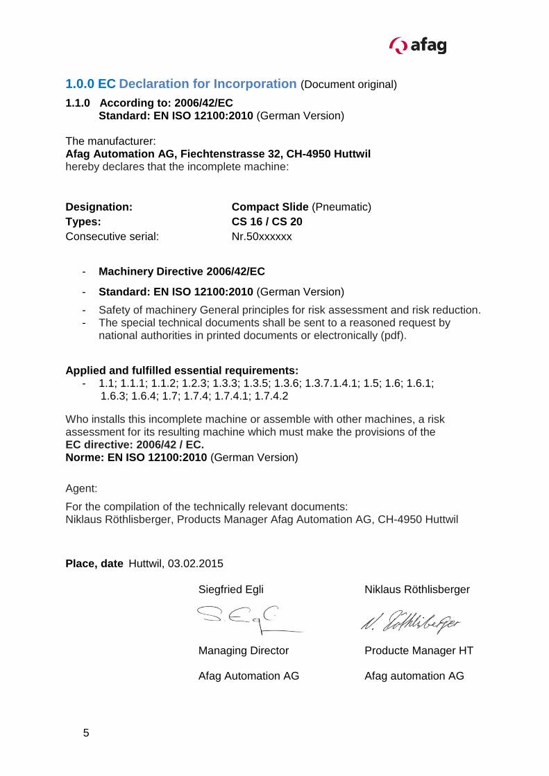
1.0.0 EC Declaration for Incorporation (Document original)
1.1.0 According to: 2006/42/EC Standard: EN ISO 12100:2010 (German Version) The manufacturer: Afag Automation AG, Fiechtenstrasse 32, CH-4950 Huttwil hereby declares that the incomplete machine:
Designation: Compact Slide (Pneumatic)
Types: CS 16 / CS 20
Consecutive serial: Nr.50xxxxxx
- Machinery Directive 2006/42/EC
- Standard: EN ISO 12100:2010 (German Version)
- Safety of machinery General principles for risk assessment and risk reduction. - The special technical documents shall be sent to a reasoned request by
national authorities in printed documents or electronically (pdf).
Who installs this incomplete machine or assemble with other machines, a risk assessment for its resulting machine which must make the provisions of the EC directive: 2006/42 / EC. Norme: EN ISO 12100:2010 (German Version)
Agent:
For the compilation of the technically relevant documents: Niklaus Röthlisberger, Products Manager Afag Automation AG, CH-4950 Huttwil
Place, date Huttwil, 03.02.2015
Siegfried Egli Niklaus Röthlisberger
Managing Director Producte Manager HT Afag Automation AG Afag automation AG
5
CS 16-CS 20-OI-vers.5.0 gb. 03.02.15
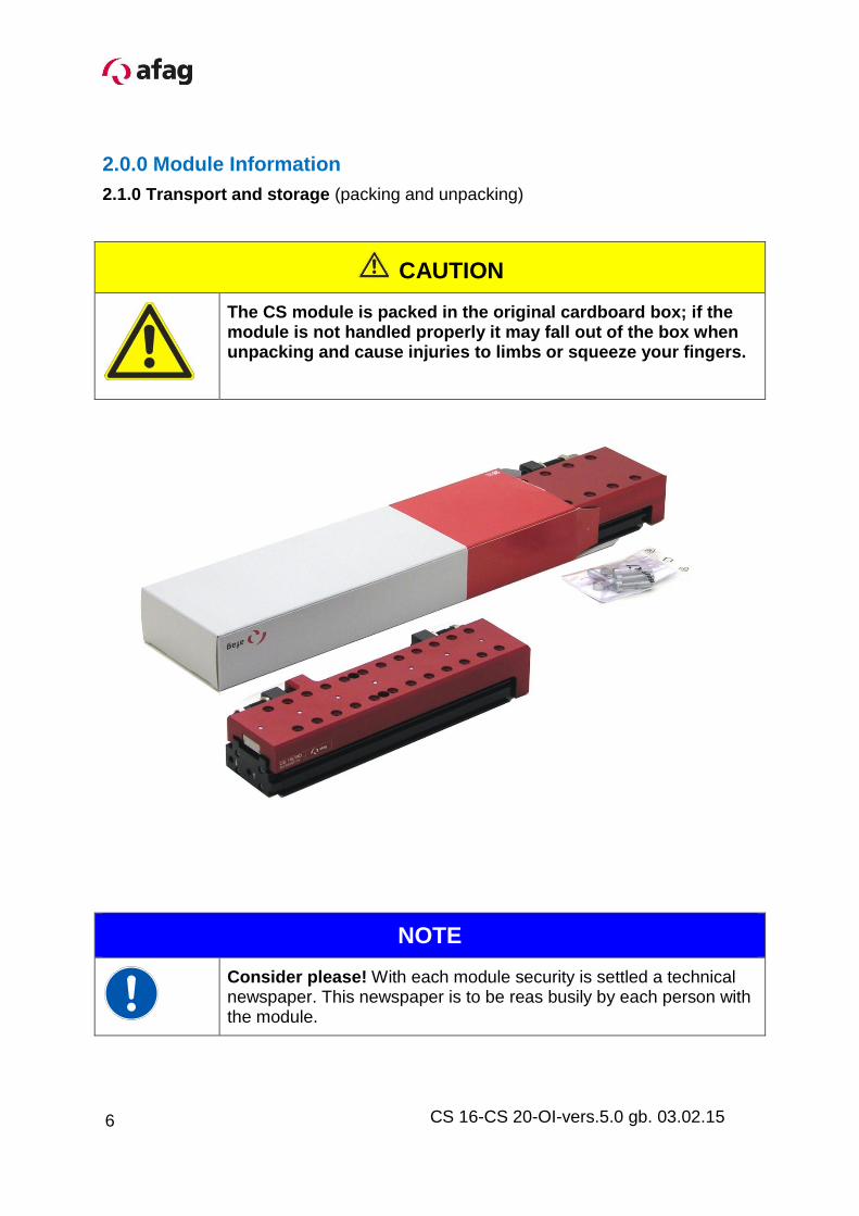
2.0.0 Module Information
2.1.0 Transport and storage (packing and unpacking)
CAUTION
The CS module is packed in the original cardboard box; if the module is not handled properly it may fall out of the box when unpacking and cause injuries to limbs or squeeze your fingers.
NOTE
Consider please! With each module security is settled a technical newspaper. This newspaper is to be reas busily by each person with the module.
6
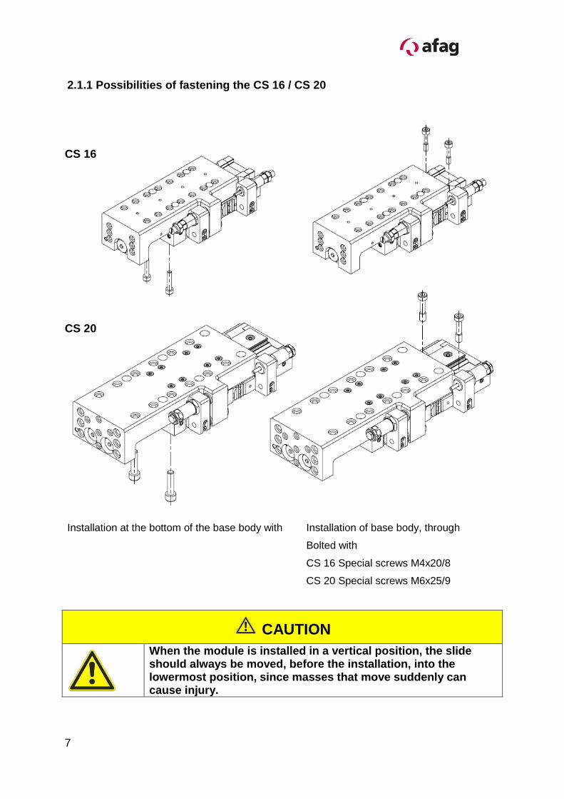
2.1.1 Possibilities of fastening the CS 16 / CS 20
Installation at the bottom of the base body with Installation of base body, through
Bolted with
CS 16 Special screws M4x20/8
CS 20 Special screws M6x25/9
CAUTION
When the module is installed in a vertical position, the slide should always be moved, before the installation, into the lowermost position, since masses that move suddenly can cause injury.
CS 16
CS 20
7
CS 16-CS 20-OI-vers.5.0 gb. 03.02.15
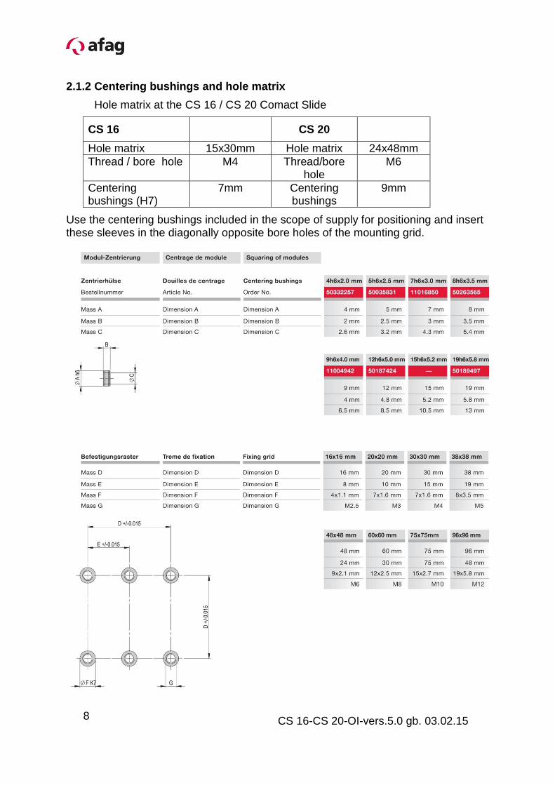
2.1.2 Centering bushings and hole matrix
Hole matrix at the CS 16 / CS 20 Comact Slide
CS 16 CS 20
Hole matrix 15x30mm Hole matrix 24x48mm
Thread / bore hole M4 Thread/bore hole
M6
Centering bushings (H7)
7mm Centering bushings
9mm
Use the centering bushings included in the scope of supply for positioning and insert these sleeves in the diagonally opposite bore holes of the mounting grid.
8
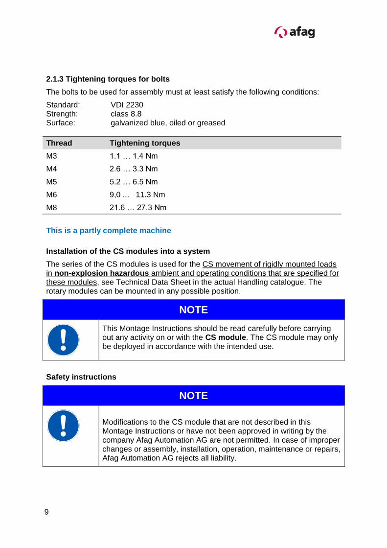
2.1.3 Tightening torques for bolts
The bolts to be used for assembly must at least satisfy the following conditions:
Standard: VDI 2230 Strength: class 8.8 Surface: galvanized blue, oiled or greased
Thread Tightening torques
M3 1.1 … 1.4 Nm
M4 2.6 … 3.3 Nm
M5 5.2 … 6.5 Nm
M6 9,0 ... 11.3 Nm
M8 21.6 … 27.3 Nm
This is a partly complete machine
Installation of the CS modules into a system
The series of the CS modules is used for the CS movement of rigidly mounted loads in non-explosion hazardous ambient and operating conditions that are specified for these modules, see Technical Data Sheet in the actual Handling catalogue. The rotary modules can be mounted in any possible position.
NOTE
This Montage Instructions should be read carefully before carrying out any activity on or with the CS module. The CS module may only be deployed in accordance with the intended use.
Safety instructions
NOTE
Modifications to the CS module that are not described in this Montage Instructions or have not been approved in writing by the company Afag Automation AG are not permitted. In case of improper changes or assembly, installation, operation, maintenance or repairs, Afag Automation AG rejects all liability.
9
CS 16-CS 20-OI-vers.5.0 gb. 03.02.15
2.1.4 Slide unit load factors CS 16
10
2.1.5 Preferred combinations CS 16
11
CS 16-CS 20-OI-vers.5.0 gb. 03.02.15
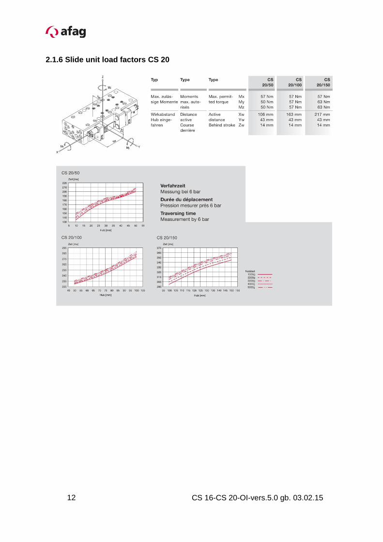
2.1.6 Slide unit load factors CS 20
12
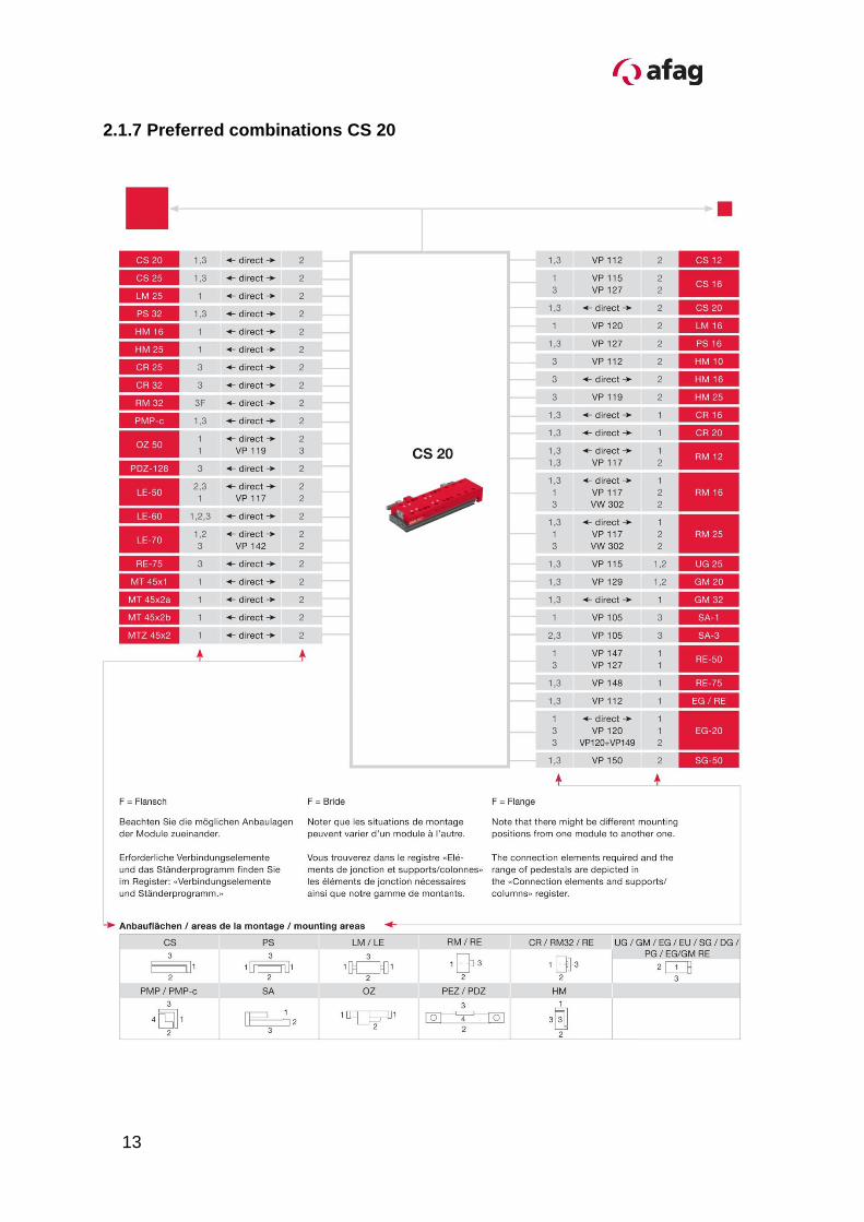
2.1.7 Preferred combinations CS 20
13
CS 16-CS 20-OI-vers.5.0 gb. 03.02.15
3.0.0 Montage Instructions (Document original)
3.1.0 Manufacturer address: Afag Automation AG
Fiechtenstrasse 32
CH-4950 Huttwil
Sales Handling:
Tel. 0041 (0)62 959 87 02
www.afag.com
These operating instructions apply to:
Product name: Compact Slide (pneumatic)
Types: CS 16/30; CS 16/60; CS 16/90; CS 16/120
CS 20/50; CS 20/100; CS 20/150
Consecutive Series: No. 50xxxxxx
This is an incomplete machine
Who installs this incomplete machine or assemble with other machines, a risk assessment for its resulting machine which must make the provisions of the EC directive: 2006/42/EC Standard: EN ISO 12100:2010 (German version)
Agent:
For the compilation of the technically relevant documents: Niklaus Röthlisberger, Products Manager Afag Automation AG, CH-4950 Huttwil
Assembly and initial start-up must be carried out by qualified personnel only and according to these instructions.
CAUTION
Indicates a possibly dangerous situation.
Non-compliance with this information can result in damage to property or light to medium personal injuries.
NOTE
Indicates general notes, useful operator tips and operating recommendations which don't affect safety and health of the personnel.
3.1.2 General description
This is an incomplete machine
The series of the CS 16-25 Compact Slide is used for the linear, smooth movement of rigidly mounted loads under the ambient and operating conditions defined, see Technical data.
The CS 16-25 Compact Slide can be installed in the horizontal or vertical position.
Modifications on the CS 16-20 Compact Slide that are not described in these Montage Instructions or have not been approved in writing by Afag Automation AG are not permitted. In case of improper changes or assembly, installation, operation, maintenance or repairs, Afag Automation AG rejects all liability.
15
CS 16-CS 20-OI-vers.5.0 gb. 03.02.15
3.1.3 Description of the module
1 Base body 4 C-groove for electric proximity switch
2 slide 5 Mounting possibility for inductive sensors
3 Stop sleeve and shock absorber 6 Pneumatic connections M5
The CS Compact Slide consists of the base body (1) with pneumatic connections (6) and the cylinder which operates the slide (2).
The stop positions are set by means of a stop sleeve with integrated shock absorber (3).
The stop position is queried by means of the PNP proximity switch Ø 4mm mounted with a sliding block (sensor not included in the scope of supply, please see “Accessories”).
An inductive sensor (5) can also be used as alternative to the electric proximity switch (4).
6
1
4
2
3
5
5 3
16
3.1.4 Scope of supply
Quant. Description Quant. Description
2 Centering bushings 7x3 mm 2 Centering bushings 9x4 mm
4 Special screw M4x20/8 4 Special screw M6x25/9
3.1.5 Intended use
The series of the CS Compact Slide is used for the linear movement of rigidly mounted loads under the ambient and operating conditions defined for this module; see Technical catalogue.
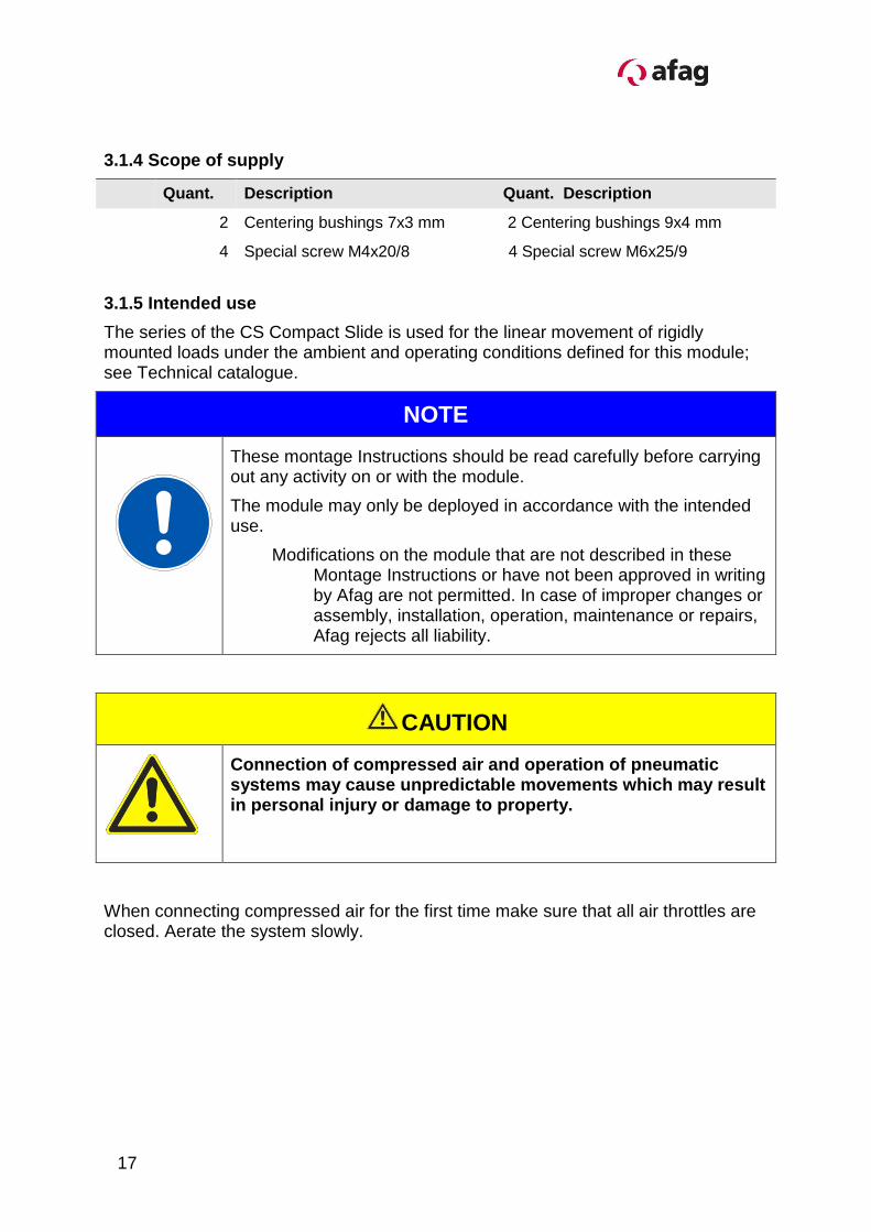
NOTE
These montage Instructions should be read carefully before carrying out any activity on or with the module.
The module may only be deployed in accordance with the intended use.
Modifications on the module that are not described in these Montage Instructions or have not been approved in writing by Afag are not permitted. In case of improper changes or assembly, installation, operation, maintenance or repairs, Afag rejects all liability.
CAUTION
Connection of compressed air and operation of pneumatic systems may cause unpredictable movements which may result in personal injury or damage to property.
When connecting compressed air for the first time make sure that all air throttles are closed. Aerate the system slowly.
17
CS 16-CS 20-OI-vers.5.0 gb. 03.02.15
3.1.6 Warranty
The module is designed for 40 million load alternations* under the ambient conditions and conditions of use defined for this module, see catalogue. Wearing parts (shock absorbers and stop screws) are excluded from the warranty. The warranty includes repair or replacement of faulty Afag parts.
*whichever comes first
When repairs are carried out by the customer without prior training or instruction by Afag AG the warranty will become void. Any additional claims are excluded.
3.1.7 Areas of application
The CS Compact Slides are exclusively designed for the linear movement of load capacities of up to 2.0 – 3.0 kg (CS 16); (CS 20 to 5 kg), in any position on the slide and maximum 1.5 - 2.0 kg (CS 16); (CS 20 to 4.0 kg) at the face side of the module; the load capacities should not affect persons, property or the environment. They can also be used in combination with other modules than Pick & Place machines, the permissible load capacities should, however, not be exceeded.
Any other use is regarded as inadequate.
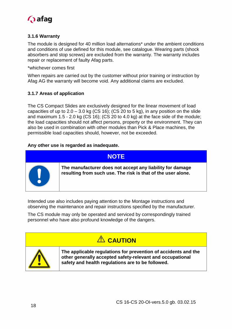
NOTE
The manufacturer does not accept any liability for damage resulting from such use. The risk is that of the user alone.
Intended use also includes paying attention to the Montage instructions and observing the maintenance and repair instructions specified by the manufacturer.
The CS module may only be operated and serviced by correspondingly trained personnel who have also profound knowledge of the dangers.
CAUTION
The applicable regulations for prevention of accidents and the other generally accepted safety-relevant and occupational safety and health regulations are to be followed.
18
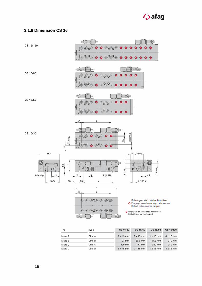
3.1.8 Dimension CS 16
19
CS 16-CS 20-OI-vers.5.0 gb. 03.02.15
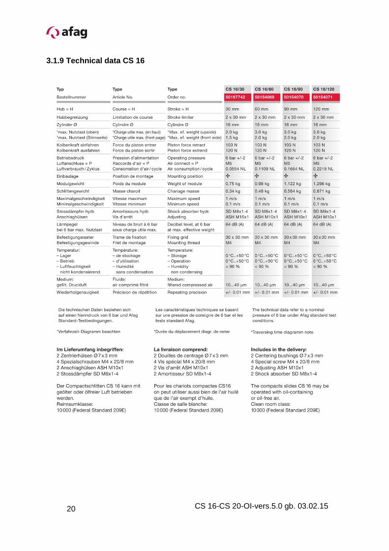
3.1.9 Technical data CS 16
20
3.2.0 Dimension CS 20
21
CS 16-CS 20-OI-vers.5.0 gb. 03.02.15
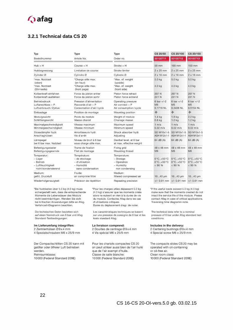
3.2.1 Technical data CS 20
22
3.2.2 Pneumatic connection for CS Module
Schematically CS Schematically CS mit ZA
1 2
Compressed air connection Maintenance unit
P1 Air connection CS (Slide from) P2 Air connection CS (Slide from)
Expiry result with ZA-application (Example Driving out)
Process: 1. Pressure onP3 (Catch drive out)
2. Pressure on P1 (Slide goes on them ZA-Catch)
3. Pressure Impuls on P2 (the CS Slide it is briefly aired)
4. Pressure on P4 (ZA-Catch drive out)
5. Pressure onP3 (Slide completely drives out)
6. Pressure on P2 (goes back in starting position)
NOTE
Minimale compressed air quality according to ISO 8573-1;
2010 (7-4-4)
1 2
4
5
3
6
23
CS 16-CS 20-OI-vers.5.0 gb. 03.02.15
3.2.3 Preparation for start-up
Adjusting the shock absorber and the stop screw
P1
Air connection (drive out)
2 Shock absorber P2 Air connection (drive on) 3 5
Stop sleeve SD-Holder
4 6
Slide Application strip
Setting the shock absorber and the stop screw
Procedure:
1. Apply compressed air to (P1), the slide is extended
2. Loosen clamping screw (1a)
3. Adjust position by turning the stop sleeve (3)
4. Adjust shock absorber by turning (2)
5. Tighten clamping screw (1a)
6. Apply compressed air to (P2), the slide (4) is retracted
7. Loosen clamping screw (1b)
8. Set position by turning the stop screw (3)
9. Adjust shock absorber by turning (2)
10. Tighten clamping screw (1b)
4
P2
P1
P2
3 2
P2
2
P2 3
P2
P1
5
5
6
24
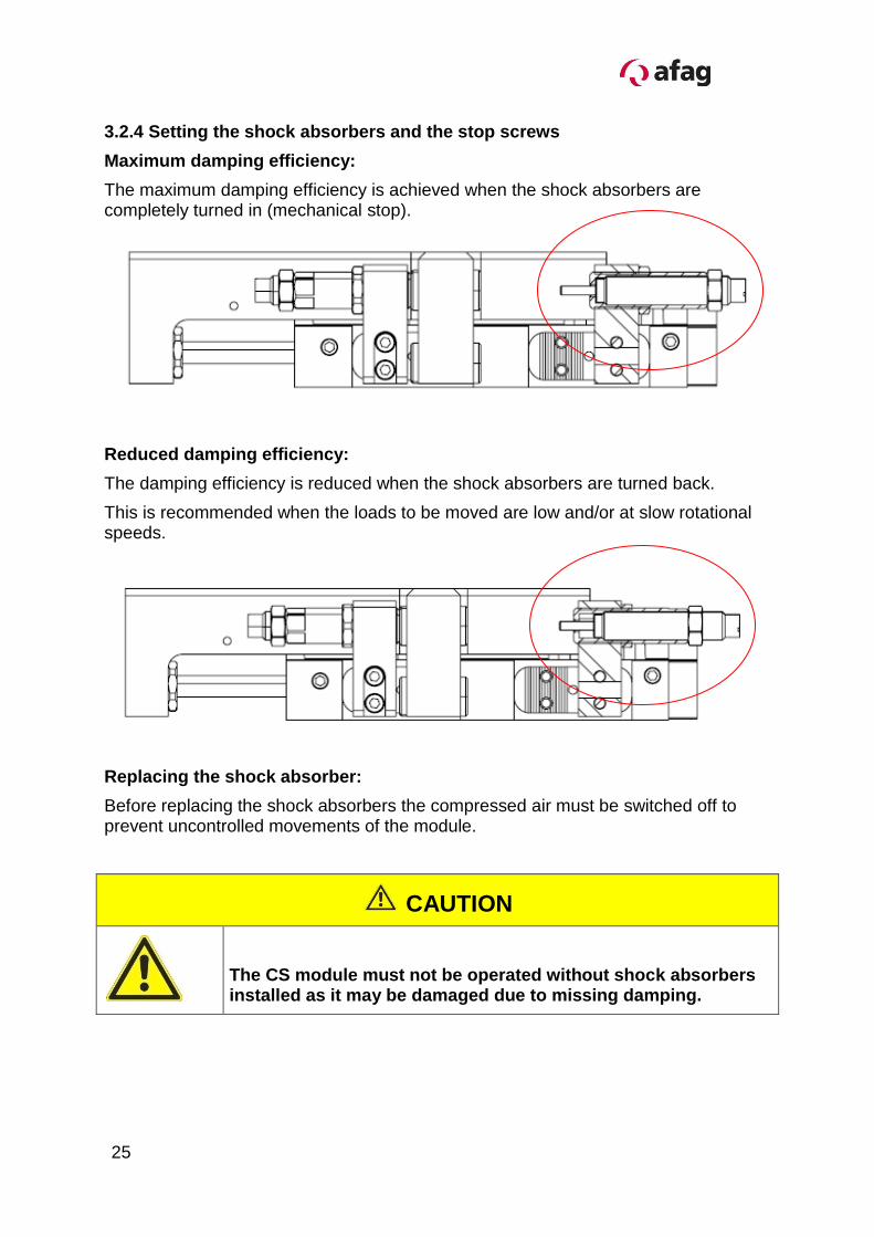
3.2.4 Setting the shock absorbers and the stop screws
Maximum damping efficiency:
The maximum damping efficiency is achieved when the shock absorbers are completely turned in (mechanical stop).
Reduced damping efficiency:
The damping efficiency is reduced when the shock absorbers are turned back.
This is recommended when the loads to be moved are low and/or at slow rotational speeds.
Replacing the shock absorber:
Before replacing the shock absorbers the compressed air must be switched off to prevent uncontrolled movements of the module.
CAUTION
The CS module must not be operated without shock absorbers installed as it may be damaged due to missing damping.
25
CS 16-CS 20-OI-vers.5.0 gb. 03.02.15
3.2.5 Installation of the sensors
Clamping proximity switches are used to query the CS stop positions.
Polling of the stop positions is monitored by an LED on the initiator. If the LED switch status does not change during inquiry of the stop positions the sensor is faulty and must be replaced.
CAUTION
The CS-module with proximity switch and initiators must not be used in an explosion-hazardous area.
NOTE
Initiators and proximity switches are not included in the scope of supply
(please see “Accessories” in the Technical Catalogue).
Only the specified proximity switches and initiators are to be used.
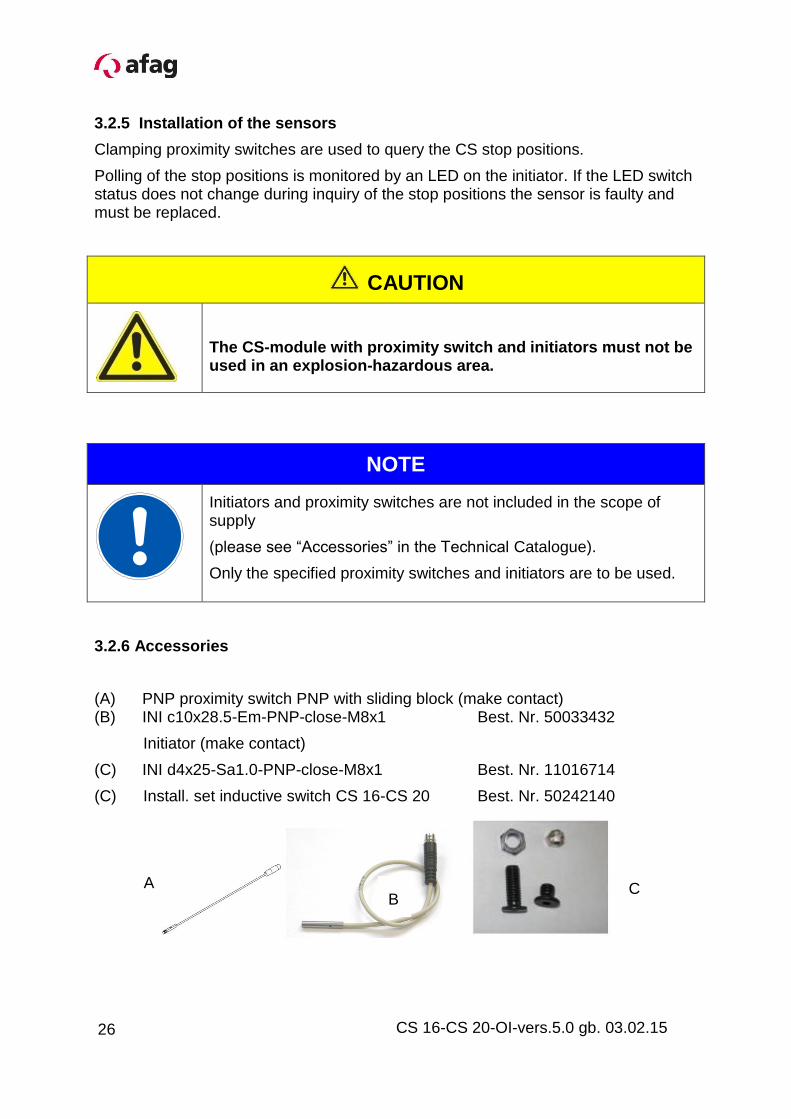
3.2.6 Accessories
(A) PNP proximity switch PNP with sliding block (make contact) (B) INI c10x28.5-Em-PNP-close-M8x1 Best. Nr. 50033432
Initiator (make contact)
(C) INI d4x25-Sa1.0-PNP-close-M8x1 Best. Nr. 11016714
(C) Install. set inductive switch CS 16-CS 20 Best. Nr. 50242140
A B
C
26
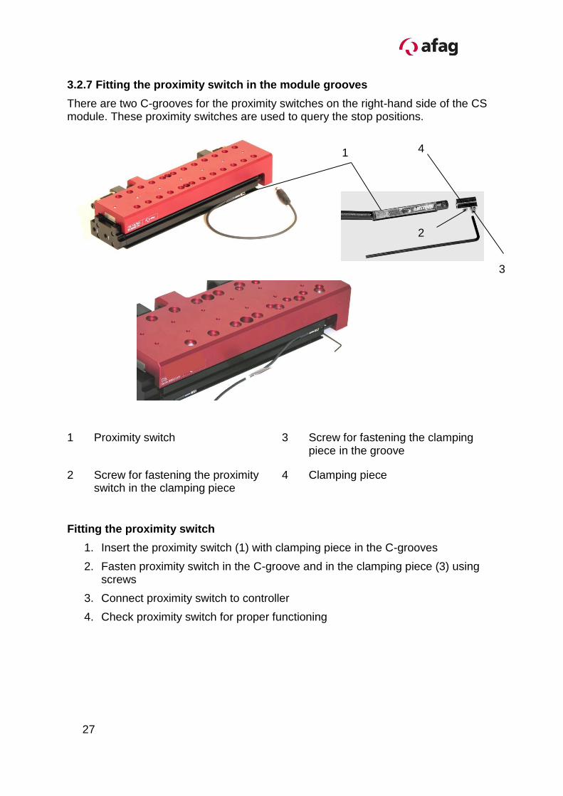
3.2.7 Fitting the proximity switch in the module grooves
There are two C-grooves for the proximity switches on the right-hand side of the CS module. These proximity switches are used to query the stop positions.
1 Proximity switch 3 Screw for fastening the clamping piece in the groove
2 Screw for fastening the proximity switch in the clamping piece
4 Clamping piece
Fitting the proximity switch
1. Insert the proximity switch (1) with clamping piece in the C-grooves
2. Fasten proximity switch in the C-groove and in the clamping piece (3) using screws
3. Connect proximity switch to controller
4. Check proximity switch for proper functioning
1
3
2
4
27
CS 16-CS 20-OI-vers.5.0 gb. 03.02.15
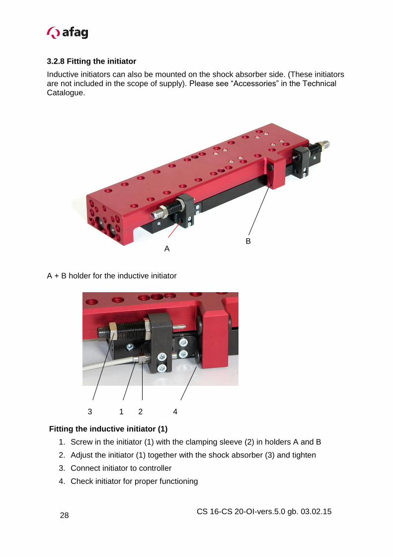
3.2.8 Fitting the initiator
Inductive initiators can also be mounted on the shock absorber side. (These initiators are not included in the scope of supply). Please see “Accessories” in the Technical Catalogue.
A + B holder for the inductive initiator
Fitting the inductive initiator (1)
1. Screw in the initiator (1) with the clamping sleeve (2) in holders A and B
2. Adjust the initiator (1) together with the shock absorber (3) and tighten
3. Connect initiator to controller
4. Check initiator for proper functioning
A B
1 2 3
4
28
3.2.9 Check of the final position in the total stroke range
The complete mounting kit, consisting of
1 Special screw M6 1 Lock nut 1 Clamping sleeve must be used for this.
It can be ordered under the order no. 50242140.
The screw head is used as reference and the screw can be adjusted – depending on the desired combination - using the shock absorber. Due to the adjustability of the screw, the final position can now be sensed over the entire stroke range by means of an inductive sensor.
Sensor is referenced at the adjustable Final position control at max. stroke screw head Stroke reduction Can reduce stroke by turning the bar of the user application Use the bar remove and rotate when the stroke has to be further reduced. By screwing a screw into the thread in the middle (see arrow), the use of bar, take out the bar, the use should be facilitated.
Before after after normal state of reduced stroke
29
CS 16-CS 20-OI-vers.5.0 gb. 03.02.15
3.3.0 Start-up of the CS Compact Slide
Aerate the total system slowly.
Pay attention to the permissible values (technical data) regarding:
- load capacity
- motion frequency
- moment loads on the guide system
CAUTION
Limbs may be squeezed by moving components.
Make sure that there are no persons or tools within the operating range of the module.
Carry out a test run
- at first at slow traverse speed,
- afterwards under operating conditions.
30
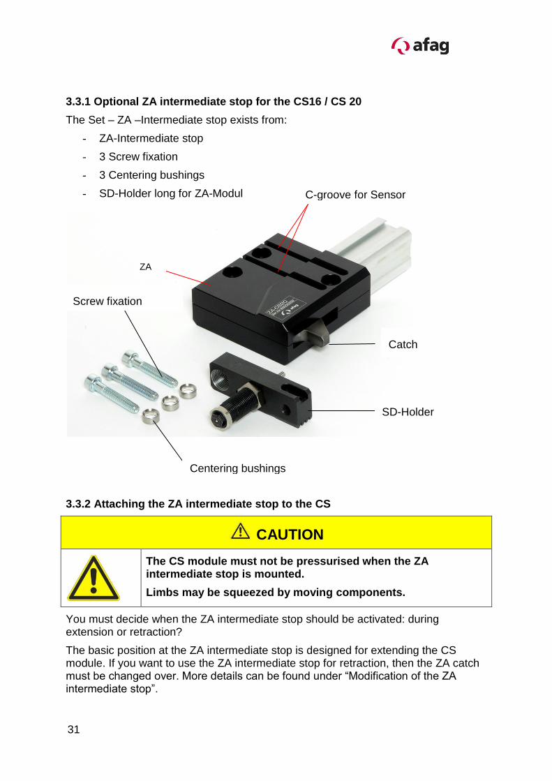
3.3.1 Optional ZA intermediate stop for the CS16 / CS 20
The Set – ZA –Intermediate stop exists from:
- ZA-Intermediate stop
- 3 Screw fixation
- 3 Centering bushings
- SD-Holder long for ZA-Modul
3.3.2 Attaching the ZA intermediate stop to the CS
CAUTION
The CS module must not be pressurised when the ZA intermediate stop is mounted.
Limbs may be squeezed by moving components.
You must decide when the ZA intermediate stop should be activated: during extension or retraction?
The basic position at the ZA intermediate stop is designed for extending the CS module. If you want to use the ZA intermediate stop for retraction, then the ZA catch must be changed over. More details can be found under “Modification of the ZA intermediate stop”.
C-groove for Sensor
Centering bushings
ZA
Screw fixation
Catch
SD-Holder
31
CS 16-CS 20-OI-vers.5.0 gb. 03.02.15
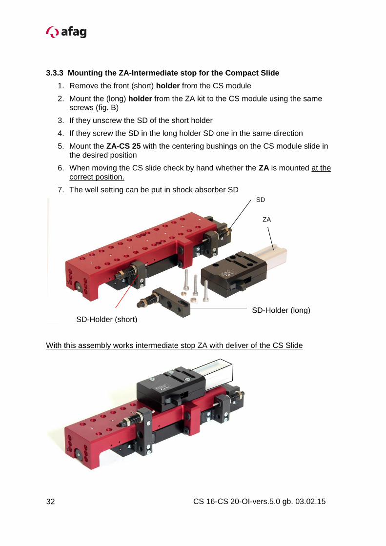
3.3.3 Mounting the ZA-Intermediate stop for the Compact Slide
1. Remove the front (short) holder from the CS module
2. Mount the (long) holder from the ZA kit to the CS module using the same screws (fig. B)
3. If they unscrew the SD of the short holder
4. If they screw the SD in the long holder SD one in the same direction
5. Mount the ZA-CS 25 with the centering bushings on the CS module slide in the desired position
6. When moving the CS slide check by hand whether the ZA is mounted at the correct position.
7. The well setting can be put in shock absorber SD
With this assembly works intermediate stop ZA with deliver of the CS Slide
SD-Holder (short) SD-Holder (long)
ZA
SD
32
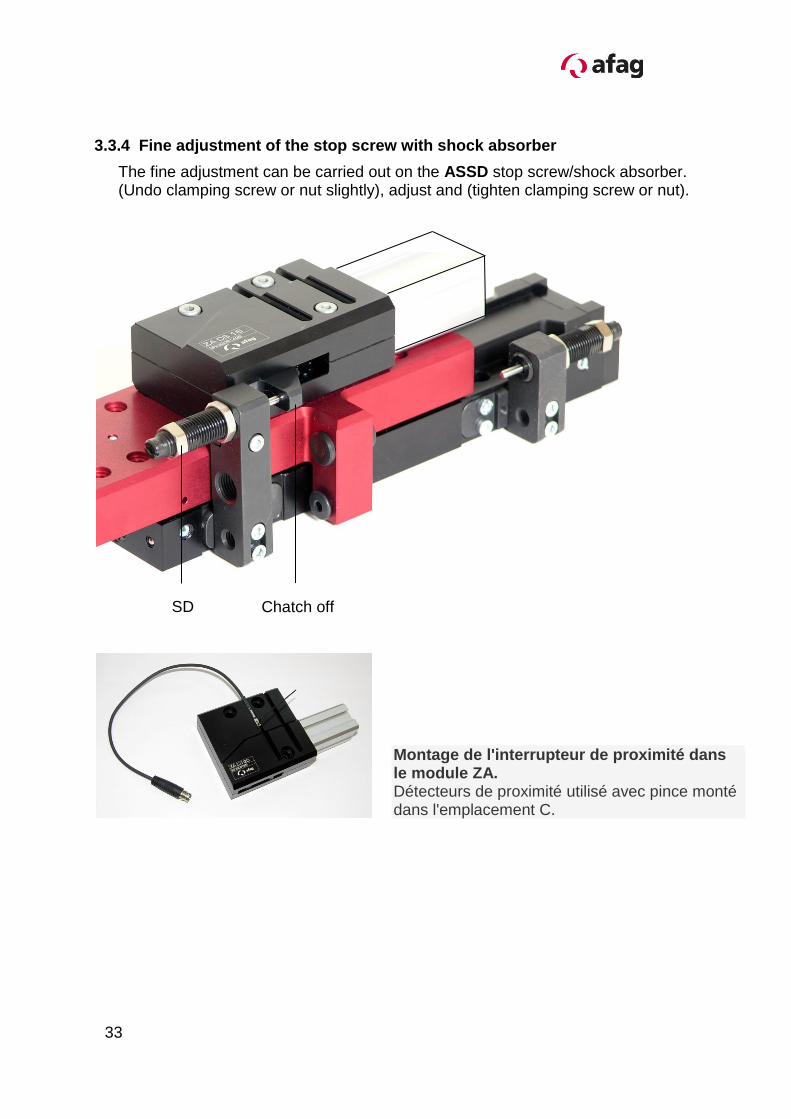
3.3.4 Fine adjustment of the stop screw with shock absorber
The fine adjustment can be carried out on the ASSD stop screw/shock absorber. (Undo clamping screw or nut slightly), adjust and (tighten clamping screw or nut).
SD Chatch off
Montage de l'interrupteur de proximité dans le module ZA.
Détecteurs de proximité utilisé avec pince monté dans l'emplacement C.
33
CS 16-CS 20-OI-vers.5.0 gb. 03.02.15
3.3.5 Operating sequence of the intermediate position when extending
Positions Pressure on Description
1
P1
P4
Slide rear Catch on
2
P1
P3
Slide rear Catch off
3
P2
P3
Slide moves to intermediate position Catch off
4
P2
Pulse on P1
(approx.0.2sec venting)
Before starting from the intermediate position, both air chambers must absolutely be vented so that the empty air chambers are not moved to and the exhaust air flow control can function. Otherwise module damage must be expected
5
P4 Catch on
6
P2
P4
Slide moves to the front Catch on
7
P1
P4
Slide returns to home position (slide rear) Catch on
34
Operating sequence of the intermediate position when returing
Positions Pressure on
Description
1
P1
P4
Slide rear Catch off
2
P2
P4
Slide moves to the front Catch off
3
P2
P3
Slide front Catch off
4
P1
P3
Slide moves to intermediate position Catch off
5
P1
Pulse on
Approx. P2
(ca.0.2sec venting)
Before starting from the intermediate position, both air chambers must absolutely be vented so that the amply air chambers are not moved to and the exhaust air flow control can function. Otherwise module damage must be expected
6
P4 Catch on
7
P1
P4
Slide returns to home position (slide rear) Catch on
35
CS 16-CS 20-OI-vers.5.0 gb. 03.02.15
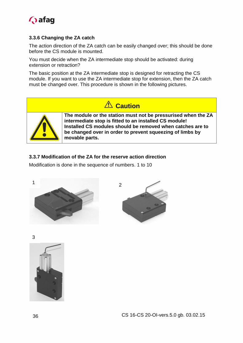
3.3.6 Changing the ZA catch
The action direction of the ZA catch can be easily changed over; this should be done before the CS module is mounted.
You must decide when the ZA intermediate stop should be activated: during extension or retraction?
The basic position at the ZA intermediate stop is designed for retracting the CS module. If you want to use the ZA intermediate stop for extension, then the ZA catch must be changed over. This procedure is shown in the following pictures.
Caution
The module or the station must not be pressurised when the ZA intermediate stop is fitted to an installed CS module! Installed CS modules should be removed when catches are to be changed over in order to prevent squeezing of limbs by movable parts.
3.3.7 Modification of the ZA for the reserve action direction
Modification is done in the sequence of numbers. 1 to 10
1 2
3
36
NOTE
Normally, the catch is not greased!
The grease is missing on the pictures so that the individual parts are clearly visible!
Ensure that the air connections at the cylinder are not positioned at the side of the catch!
4 5
6 7
8
9
10
37
CS 16-CS 20-OI-vers.5.0 gb. 03.02.15
CAUTION
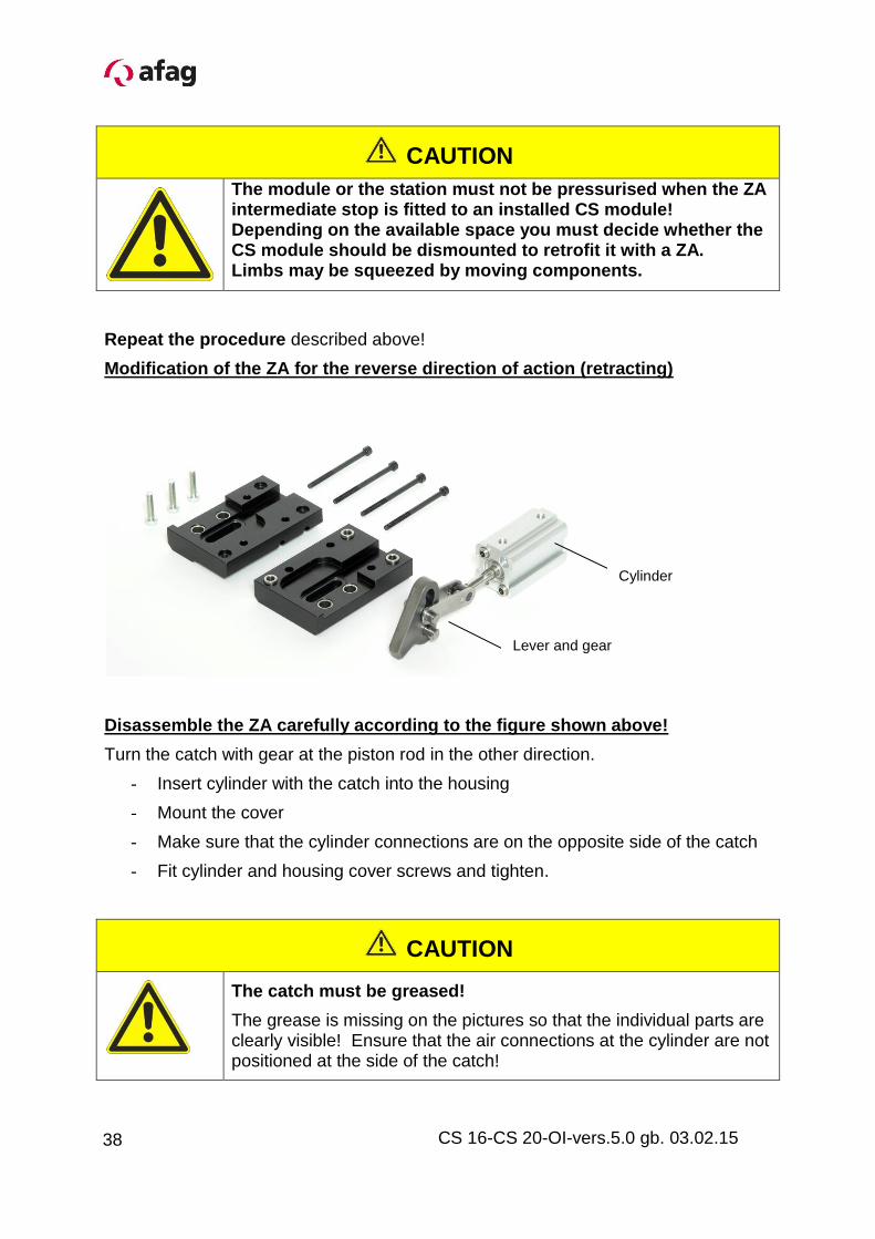
The module or the station must not be pressurised when the ZA intermediate stop is fitted to an installed CS module! Depending on the available space you must decide whether the CS module should be dismounted to retrofit it with a ZA. Limbs may be squeezed by moving components.
Repeat the procedure described above!
Modification of the ZA for the reverse direction of action (retracting)
Disassemble the ZA carefully according to the figure shown above!
Turn the catch with gear at the piston rod in the other direction.
- Insert cylinder with the catch into the housing
- Mount the cover
- Make sure that the cylinder connections are on the opposite side of the catch
- Fit cylinder and housing cover screws and tighten.
CAUTION
The catch must be greased!
The grease is missing on the pictures so that the individual parts are clearly visible! Ensure that the air connections at the cylinder are not positioned at the side of the catch!
Lever and gear
Cylinder
38
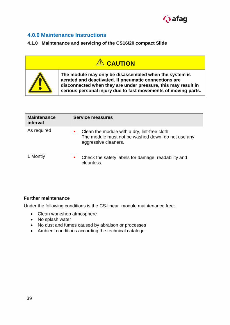
4.0.0 Maintenance Instructions
4.1.0 Maintenance and servicing of the CS16/20 compact Slide
CAUTION
The module may only be disassembled when the system is aerated and deactivated. If pneumatic connections are disconnected when they are under pressure, this may result in serious personal injury due to fast movements of moving parts.
Maintenance interval
Service measures
As required Clean the module with a dry, lint-free cloth. The module must not be washed down; do not use any aggressive cleaners.
1 Montly Check the safety labels for damage, readability and cleunless.
Further maintenance
Under the following conditions is the CS-linear module maintenance free:
Clean workshop atmosphere
No splash water
No dust and fumes caused by abraison or processes
Ambient conditions according the technical cataloge
39
CS 16-CS 20-OI-vers.5.0 gb. 03.02.15
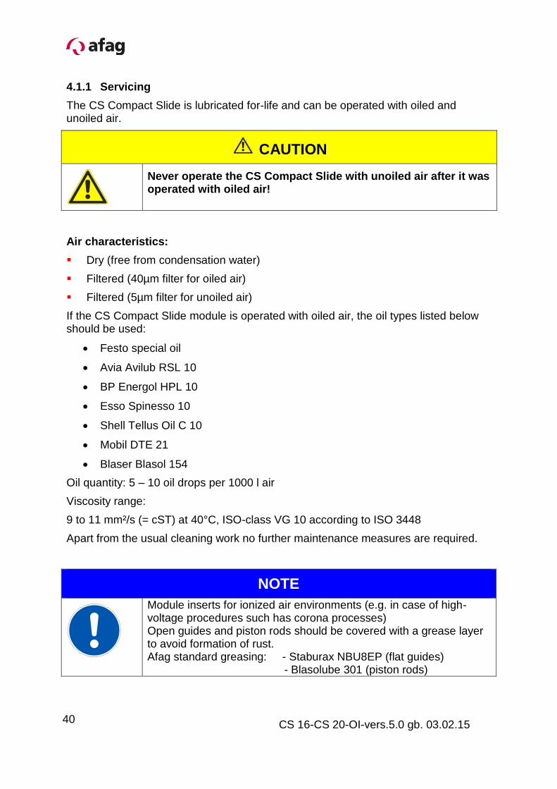
4.1.1 Servicing
The CS Compact Slide is lubricated for-life and can be operated with oiled and unoiled air.
CAUTION
Never operate the CS Compact Slide with unoiled air after it was operated with oiled air!
Air characteristics:
Dry (free from condensation water)
Filtered (40µm filter for oiled air)
Filtered (5µm filter for unoiled air)
If the CS Compact Slide module is operated with oiled air, the oil types listed below should be used:
Festo special oil
Avia Avilub RSL 10
BP Energol HPL 10
Esso Spinesso 10
Shell Tellus Oil C 10
Mobil DTE 21
Blaser Blasol 154
Oil quantity: 5 – 10 oil drops per 1000 l air
Viscosity range:
9 to 11 mm²/s (= cST) at 40°C, ISO-class VG 10 according to ISO 3448
Apart from the usual cleaning work no further maintenance measures are required.
NOTE
Module inserts for ionized air environments (e.g. in case of high-voltage procedures such has corona processes) Open guides and piston rods should be covered with a grease layer to avoid formation of rust. Afag standard greasing: - Staburax NBU8EP (flat guides) - Blasolube 301 (piston rods)
40
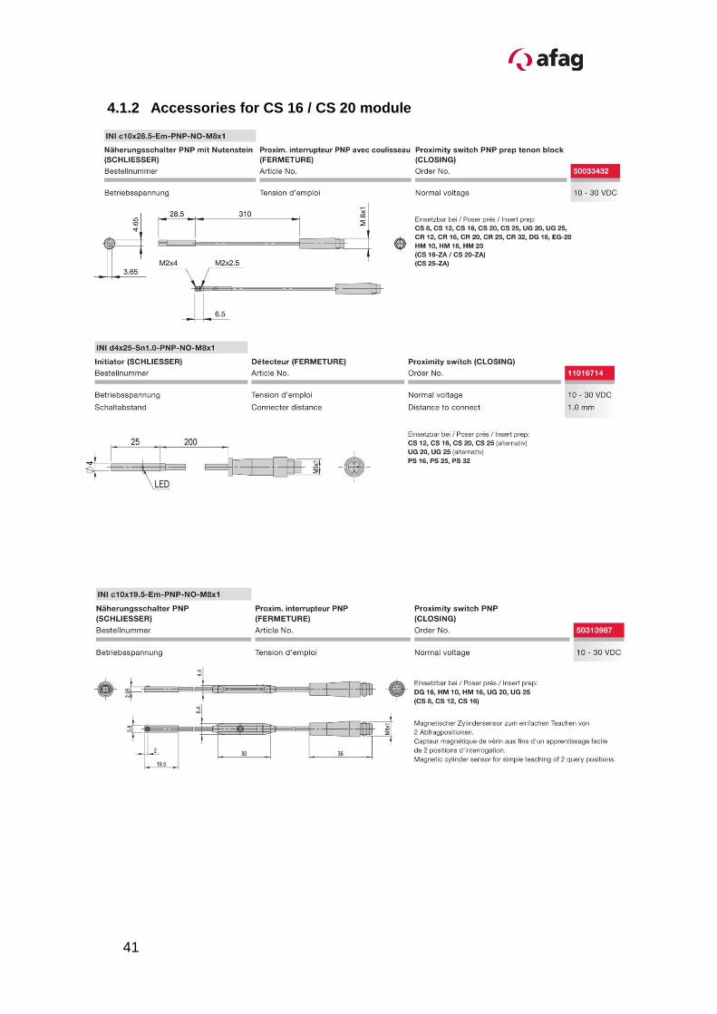
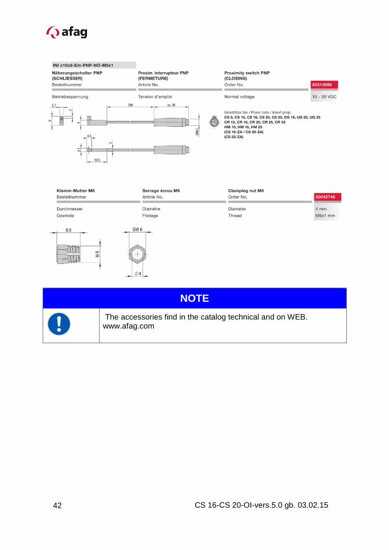
4.1.2 Accessories for CS 16 / CS 20 module
41
CS 16-CS 20-OI-vers.5.0 gb. 03.02.15
NOTE
The accessories find in the catalog technical and on WEB. www.afag.com
42
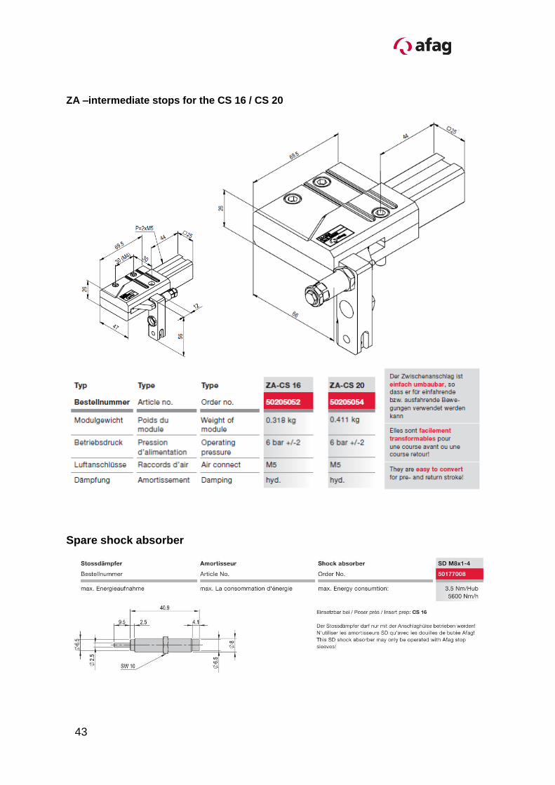
ZA –intermediate stops for the CS 16 / CS 20
Spare shock absorber
43
CS 16-CS 20-OI-vers.5.0 gb. 03.02.15
4.1.3 Faults during operation
Fault Possible cause Fault clearance
The CS Compact Slide hits hard in the stop positions
The stopper/shock absorber is not correctly adjusted.
Readjust stopper/shock absorber
The CS module hits hard again in the stop positions
Shock absorber defective Replace shock absorber
(see “Accessories”)
The CS module stops in one stop position
No signal on the proximity switch/sensor
Reset proximity switch/sensor
The CS module stops again in the stop positions
Sensor defective Replace sensor
(see “Accessories”)
44
4.1.4 Disassembly and repair
When the module is damaged it can be returned to Afag Automation AG for repair.
CAUTION
The module may only be disassembled when the system is aerated and deactivated. If pneumatic connections are disconnected when they are under pressure, this may result in serious personal injury due to fast movements of moving parts.
When can the modules be repaired by the customer?
Wearing parts can be exchanged by the customer itself when the warranty has expired.
NOTE
All the other faulty parts must exclusively be replaced by company Afag Automation AG!
When the customer detects that the respective module is still under warranty:
- The returns the module to company Afag Automation AG for repair.
- If the warranty has already expired, the customer must decide whether he repairs the module by himself and orders the wearing parts kit or whether he returns the module to company Afag Automation AG for repair.
NOTE
Afag offers a reliable repair service. Please note that Afag does not warranty for parts which were not repaired by Afag Automation AG.
45
CS 16-CS 20-OI-vers.5.0 gb. 03.02.15
4.1.5 Disposal
NOTE
CS modules which cannot be used any more must not be disposed off as a complete unit, but must be disassembled and recycled according to the type of material.
Materials than cannot be recycled must be disposed off in accordance with the legal regulations.