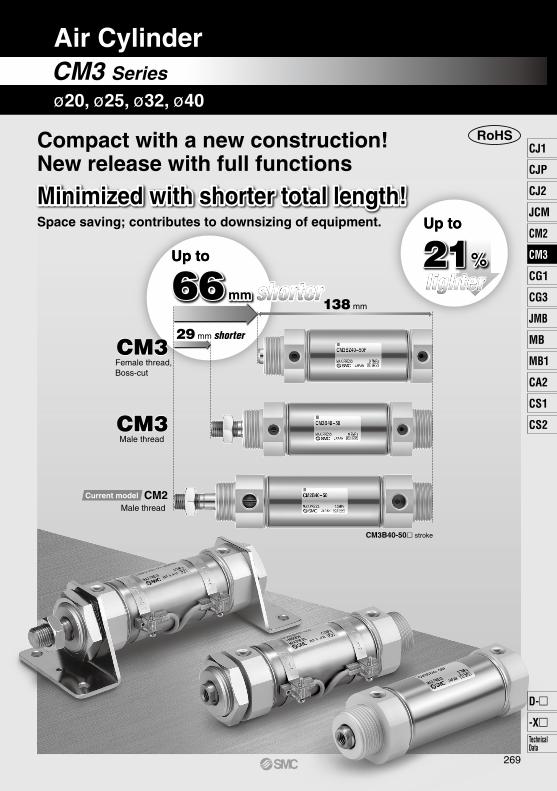
RoHS Space saving; contributes to downsizing of equipment. 138 mm CM3B40-50stroke Up to Up to Up to Up to shorter shorter Minimized with shorter total length! Minimized with shorter total length! Compact with a new construction! New release with full functions 21% 21% 66 mm 66 mm lighter lighter CM3 CM3 CM2 Female thread, Boss-cut Male thread Male thread CM3 CM3 Current model 29 mm shorter CM3 Series Air Cylinder ø20, ø25, ø32, ø40 269 CJ1 CJP CJ2 JCM CM2 CG1 CG3 MB JMB MB1 CA2 CS1 CS2 D--XTechnical Data CM3
Transcript
RoHS
Space saving; contributes to downsizing of equipment.
138 mm
CM3B40-50 stroke
Up toUp to
Up toUp to
shortershorter
Minimized with shorter total length!Minimized with shorter total length!
Compact with a new construction!New release with full functions
21%21%
66 mm66 mmlighterlighter
CM3CM3
CM2
Female thread,Boss-cut
Male thread
Male thread
CM3CM3
Current model
29 mm shorter
CM3 Series
Air Cylinder
ø20, ø25, ø32, ø40
269
CJ1
CJP
CJ2
JCM
CM2
CM3
CG1
CG3
MB
JMB
MB1
CA2
CS1
CS2
D-
-XTechnicalData
CM3
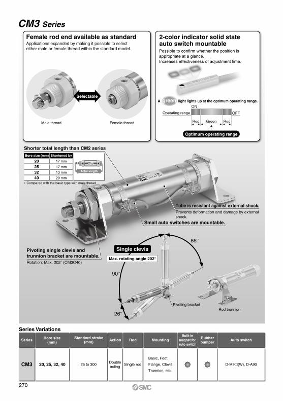
CM3 Series
Applications expanded by making it possible to select either male or female thread within the standard model.
Female rod end available as standard
Male thread Female thread
Selectable
2-color indicator solid state auto switch mountablePossible to confirm whether the position is appropriate at a glance. Increases effectiveness of adjustment time.
A green light lights up at the optimum operating range.
Operating range OFF
ON
Red Green Red
Optimum operating range
86°
90°
26°
Single clevis
Max. rotating angle 202°
Pivoting bracketRod trunnion
Series Variations
Series Bore size(mm) Action
Doubleacting
Rod
Single rod D-M9(W), D-A90
Built-inmagnet forauto switch
Rubberbumper Auto switch
20, 25, 32, 40 25 to 300
Basic, Foot,
Flange, Clevis,
Trunnion, etc.
CM3
MountingStandard stroke(mm)
Shorter total length than CM2 series
Pivoting single clevis and trunnion bracket are mountable.Rotation: Max. 202˚ (CM3C40)
Small auto switches are mountable.
Bore size (mm) Shortened by
20253240
17 mm
17 mm
13 mm
29 mm∗ Compared with the basic type with male thread
Total length
Tube is resistant against external shock.Prevents deformation and damage by external shock.
270
ALA
H
C
RoHS
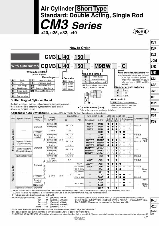
Note) This symbol is indicated when the D-A9 or M9 type auto switch is specified.This mounting bracket does not apply to other auto switches (D-C7 and H7, etc.) (Nil)
M9BWWith auto switch CDM3
CM3 L
L 150
MountingBLFGCDU
TE
BZFZUZ
BasicFoot
Rod flangeHead flangeSingle clevisDouble clevisRod trunnion
Head trunnionIntegrated clevisBoss-cut/Basic
Boss-cut/Rod flangeBoss-cut/Rod trunnion
Cylinder stroke (mm)Refer to the next page for standard strokes.
NilSn
2 pcs.1 pc.
“n” pcs.
Number of auto switches
Auto switch mounting bracke Note)
NilFG
Male threadFemale thread
Long male rod end∗
Rod end thread
Auto switch
Bore size20253240
20 mm25 mm32 mm40 mm
With auto switch(Built-in magnet)
40
40
150
Without auto switch Nil
∗ For applicable auto switches, refer to the below table.
Applicable Auto Switches/Refer to pages 1575 to 1701 for further information on auto switches.
Built-in Magnet Cylinder ModelIf a built-in magnet cylinder without an auto switch is required, there is no need to enter the symbol for the auto switch.(Example) CDM3F32-100
A96
A93A90B54B64
C73CC80CA33AA34AA44AB59W
A96V
A93V∗2
A90V
M9NM9PM9BH7C
G39AK39AM9NWM9PWM9BW
M9NA∗1
M9PA∗1
M9BA∗1
H7NF
M9NVM9PVM9BV
M9NWVM9PWVM9BWV
M9NAV∗1
M9PAV∗1
M9BAV∗1
5 V
12 V
—
5 V, 12 V
12 V
5 V, 12 V12 V
5 V, 12 V
12 V
5 V, 12 V
12 V5 V, 12 V
24 V
24 V
— —
100 V100 V or less100 V, 200 V200 V or less
—24 V or less
—
100 V, 200 V
—
—
∗ G: Same rod end dimensions (A, AL, H) as CM2 series.
How to Order
Type Special function Wiring(Output) DC AC In-linePerpendicular
Load voltage
Indic
ato
rlig
ht
Auto switch modelPre-wiredconnector Applicable load0.5
(Nil)
Lead wire length (m)
1(M)
3(L)
5(Z)
None(N)
Diagnostic indication(2-color indicator)
Diagnostic output (2-color indicator)
Diagnostic indication (2-color indicator)
Water resistant(2-color indicator)
Ree
d a
uto
sw
itch
So
lid s
tate
au
to s
wit
ch
Electricalentry
Grommet
Grommet
Grommet
Connector
Connector
Grommet
DIN terminal
Terminalconduit
Terminalconduit
Yes
Yes
NoNo
NoYe
sYe
sYe
s
3-wire (NPN)3-wire (PNP)
2-wire
2-wire
3-wire (NPN)
3-wire (NPN)
2-wire
2-wire
3-wire (NPN)3-wire (PNP)
3-wire (PNP)
4-wire (NPN)
3-wire(Equiv. to NPN)
2-wire
PLC
Relay,PLC
Relay,PLC
Relay,PLC
∗ Solid state auto switches marked with “ ” are produced upon receipt of order. ∗ Do not indicate suffix “N” for no lead wire on the D-A3A/A44A/G39A/K39A types. ∗ The D-G39A/K39A cannot be mounted on the bore size ø20.
∗ Lead wire length symbols: 0.5 m ·······Nil (Example) M9NW 1 m ······· M (Example) M9NWM 3 m ······· L (Example) M9NWL 5 m ······· Z (Example) M9NWZ None ······· N (Example) H7CN∗ Since there are other applicable auto switches than listed above, refer to page 286 for details.∗ For details about auto switches with pre-wired connector, refer to pages 1648 and 1649.∗ The D-A9(V), M9(V), M9W(V), M9A(V) type auto switches are shipped together, (but not assembled). (However, auto switch mounting brackets are assembled when being shipped.)
Air Cylinder Short Type Standard: Double Acting, Single Rod
CM3 Seriesø20, ø25, ø32, ø40
IC circuit
—
IC circuit—
IC circuit
—
IC circuit
IC circuit
—
IC circuit
—
IC circuit
—
——
—
————
—
—
——
—
—
∗1 Water resistant type auto switches can be mounted on the above models, but in such case SMC cannot guarantee water resistance. A water-resistant type cylinder is recommended for use in an environment which requires water resistance.
∗2 1 m type lead wire is only applicable to D-A93.
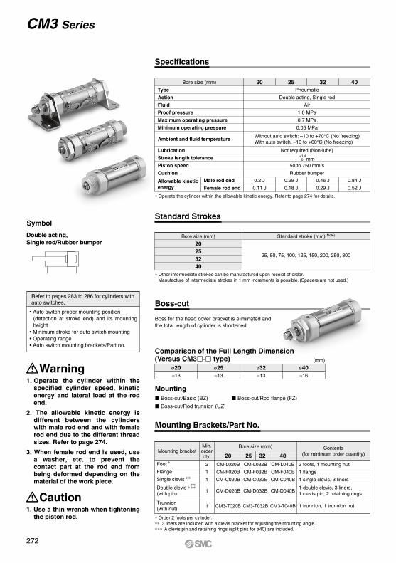
Boss for the head cover bracket is eliminated and the total length of cylinder is shortened.
(mm)
ø20–13
ø25–13
ø32–13
ø40–16
Bore size (mm)
Foot
Flange
Single clevis
Double clevis (with pin)
Trunnion(with nut)
Mounting bracketContents
(for minimum order quantity)20 25 32 402
1
1
1
1
CM-L020B
CM-F020B
CM-C020B
CM-D020B
CM3-T020B
CM-L032B
CM-F032B
CM-C032B
CM-D032B
CM3-T032B
CM-L040B
CM-F040B
CM-C040B
CM-D040B
CM3-T040B
2 foots, 1 mounting nut
1 flange
1 single clevis, 3 liners
Min.orderqty.
∗ Order 2 foots per cylinder.∗∗ 3 liners are included with a clevis bracket for adjusting the mounting angle.∗ ∗ ∗ A clevis pin and retaining rings (split pins for ø40) are included.
Mounting Brackets/Part No.
Specifications
Standard Strokes
Type
Action
Fluid
Proof pressure
Maximum operating pressure
Minimum operating pressure
Ambient and fluid temperature
Lubrication
Stroke length tolerance
Piston speed
Cushion
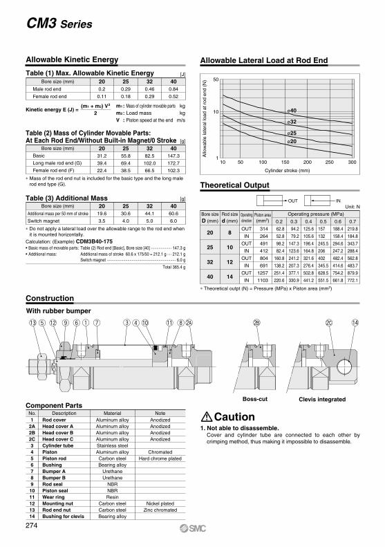
Allowable kinetic energy
Pneumatic
Double acting, Single rod
Air
1.0 MPa
0.7 MPa
0.05 MPa
Not required (Non-lube)
50 to 750 mm/s
Rubber bumper
20 25 32 40
0.2 J
0.11 J
0.29 J
0.18 J
0.46 J
0.29 J
0.84 J
0.52 J
Without auto switch: –10 to +70°C (No freezing)With auto switch: –10 to +60°C (No freezing)
+1.40 mm
Male rod end
Female rod end
Bore size (mm)
Bore size (mm)
20253240
Standard stroke (mm) Note)
25, 50, 75, 100, 125, 150, 200, 250, 300
∗ Other intermediate strokes can be manufactured upon receipt of order. Manufacture of intermediate strokes in 1 mm increments is possible. (Spacers are not used.)
∗ Operate the cylinder within the allowable kinetic energy. Refer to page 274 for details.
• Auto switch proper mounting position (detection at stroke end) and its mounting height
• Minimum stroke for auto switch mounting• Operating range• Auto switch mounting brackets/Part no.
Refer to pages 283 to 286 for cylinders with auto switches.
specified cylinder speed, kinetic energy and lateral load at the rod end.
2. The allowable kinetic energy is different between the cylinders with male rod end and with female rod end due to the different threadsizes. Refer to page 274.
3. When female rod end is used, use a washer, etc. to prevent the contact part at the rod end from being deformed depending on the material of the work piece.
Caution1. Use a thin wrench when tightening
the piston rod.
Symbol
Double acting, Single rod/Rubber bumper
Comparison of the Full Length Dimension(Versus CM3- type)
BasicLong male rod end (G)Female rod end (F)Boss-cut/BasicBoss-cut/Long male rod endBoss-cut/Female rod endIntegrated clevisIntegrated clevis/Long male rod endIntegrated clevis/Female rod endFootFlangeSingle clevisDouble clevisTrunnion
Pivoting bracketSingle knuckle jointDouble knuckle joint (with pin)Additional weight per 50 mm of strokeAdditional weight for switch magnet
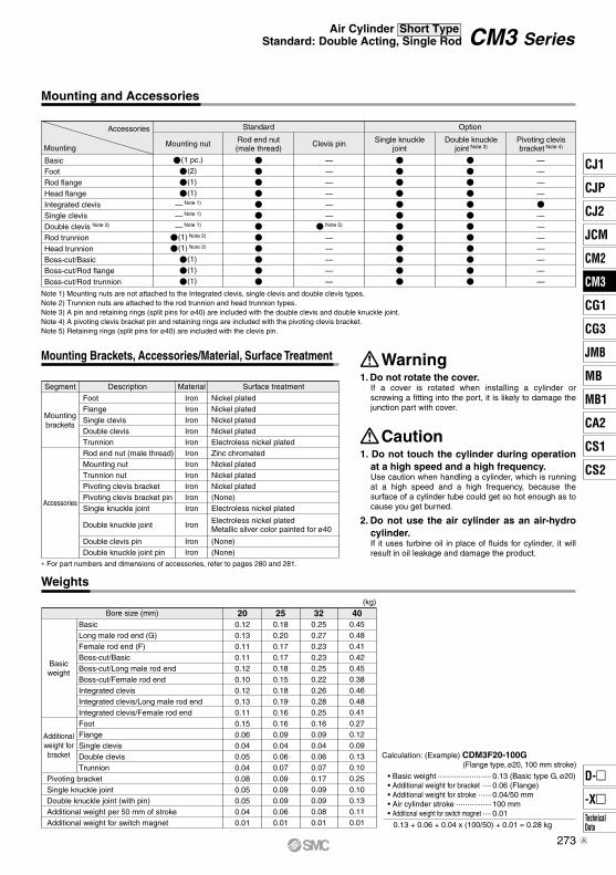
Note 1) Mounting nuts are not attached to the Integrated clevis, single clevis and double clevis types.Note 2) Trunnion nuts are attached to the rod trunnion and head trunnion types.Note 3) A pin and retaining rings (split pins for ø40) are included with the double clevis and double knuckle joint.Note 4) A pivoting clevis bracket pin and retaining rings are included with the pivoting clevis bracket.Note 5) Retaining rings (split pins for ø40) are included with the clevis pin.
∗ For part numbers and dimensions of accessories, refer to pages 280 and 281.
Electroless nickel platedMetallic silver color painted for ø40
1. Do not rotate the cover.If a cover is rotated when installing a cylinder or screwing a fitting into the port, it is likely to damage the junction part with cover.
Warning
1. Do not touch the cylinder during operation at a high speed and a high frequency.Use caution when handling a cylinder, which is running at a high speed and a high frequency, because the surface of a cylinder tube could get so hot enough as to cause you get burned.
2. Do not use the air cylinder as an air-hydro cylinder.If it uses turbine oil in place of fluids for cylinder, it will result in oil leakage and damage the product.
Caution
Calculation: (Example) CDM3F20-100G(Flange type, ø20, 100 mm stroke)
• Basic weight ························· 0.13 (Basic type G, ø20)• Additional weight for bracket ···· 0.06 (Flange)• Additional weight for stroke ······ 0.04/50 mm• Air cylinder stroke ················ 100 mm• Additional weight for switch magnet ···· 0.01
0.13 + 0.06 + 0.04 x (100/50) + 0.01 = 0.28 kg
CM3 SeriesAir Cylinder Short Type
Standard: Double Acting, Single Rod
273
CJ1
CJP
CJ2
JCM
CM2
CM3
CG1
CG3
MB
JMB
MB1
CA2
CS1
CS2
D-
-XTechnicalData
CM3
A
NoteNo.
Component PartsDescription
Rod coverHead cover AHead cover BHead cover CCylinder tubePistonPiston rodBushingBumper ABumper BRod sealPiston sealWear ringMounting nutRod end nutBushing for clevis
Table (2) Mass of Cylinder Movable Parts:At Each Rod End/Without Built-in Magnet/0 Stroke
Basic
Long male rod end (G)
Female rod end (F)
31.2
39.4
22.4
Bore size (mm)
55.8
69.4
38.5
82.5
102.0
66.5
147.3
172.7
102.3
[g]
Table (3) Additional Mass
Additional mass per 50 mm of stroke
Switch magnet
19.6
3.5
Bore size (mm)
30.6
4.0
44.1
5.0
60.6
6.0
[g]
Kinetic energy E (J) =(m1 + m2) V2
2
∗ Mass of the rod end nut is included for the basic type and the long male rod end type (G).
∗ Do not apply a lateral load over the allowable range to the rod end when it is mounted horizontally.
Calculation: (Example) CDM3B40-175• Basic mass of movable parts: Table (2) Rod end [Basic], Bore size [40] ··················· 147.3 g• Additional mass: Additional mass of stroke 60.6 x 175/50 = 212.1 g ···· 212.1 g Switch magnet ································································ 6.0 g
Total 365.4 g
m1 : Mass of cylinder movable parts kgm2 : Load mass kgV : Piston speed at the end m/s
With rubber bumper
Table (1) Max. Allowable Kinetic Energy
Allowable Kinetic Energy
Cylinder stroke (mm)
Allo
wab
le la
tera
l loa
d at
rod
end
(N
)
10
50
10
150 100 150 200 250 300
Allowable Lateral Load at Rod End
Theoretical Output
Unit: N
Bore sizeD (mm)
Rod sized (mm)
Piston area(mm2)
Operatingdirection
Operating pressure (MPa)
20
25
32
40
8
10
12
14
OUT
IN
OUT
IN
OUT
IN
OUT
IN
314
264
491
412
804
691
1257
1103
0.2 0.3
125.6
105.6
196.4
164.8
321.6
276.4
502.8
441.2
157
132
245.5
206
402
345.5
628.5
551.5
188.4
158.4
294.6
247.2
482.4
414.6
754.2
661.8
219.8
184.8
343.7
288.4
562.8
483.7
879.9
772.1
0.70.60.50.4
94.2
79.2
147.3
123.6
241.2
207.3
377.1
330.9
62.8
52.8
98.2
82.4
160.8
138.2
251.4
220.6
∗ Theoretical outpt (N) = Pressure (MPa) x Piston area (mm2)
OUT IN
ø20
ø25
ø32
ø40
1. Not able to disassemble.Cover and cylinder tube are connected to each other by crimping method, thus making it impossible to disassemble.
Caution
Boss-cut Clevis integrated
t o y q u r !0 !4!1!3 !2 ie @A @C@B
CM3 Series
Construction
274
Corner of the cover
2 x P 2 x NN
Width across flats B2
Width across flats B1
MM
Width across flats KA NA
øI
NA
R0.5
S + Stroke
ZZ + Stroke
H
ALF
øD
1.5 1.5
F
2 x
øE
h8
GGH2
H1
A
ZZ + Stroke
Female thread MMThread depth A1
HZZ + Stroke
2 x øLC
2 x P
2 x NN(Effective thread length 2 x FL)Width across flats B1
4 x øLDWidth across flats KA
Width across flats B2
Width across flats NA
MM
LZ
LX
B
LH
S + Stroke
F
GGH2
H1
YXXYLS + Stroke
øD
F
øI
ALA
H
LT
ZZZ + Stroke
ALA
ZZ + Stroke
H
Bore size StrokeFoot (L): CM3L
Boss-cut
Foot (L)Bore size
(mm)
20253240
A AL B40
47
47
54
B1
13
17
17
22
B2
26
32
32
41
D 8
10
12
14
F13
13
13
16
FL10.5
10.5
10.5
13.5
G H H1
5
6
6
8
H2
8
8
8
10
I KA LC4
4
4
4
LD6.8
6.8
6.8
7
LH25
28
28
30
LS 95
96
102
113
Bore size
20253240
LX40
40
40
55
LZ MM NA24
30
34.5
42.5
NNM20 x 1.5
M26 x 1.5
M26 x 1.5
M32 x 2
PM5 x 0.8
M5 x 0.8
Rc1/8
Rc1/8
S55
56
62
67
X20
20
20
23
Y 8
8
8
10
Z ZZ114
118
124
142
Basic (B)Bore size
(mm)
0–0.033 0–0.033 0–0.033 0–0.039
20253240
A14.5
17.5
17.5
23.5
AL12
15
15
20.5
B1
13
17
17
22
B2
26
32
32
41
D 8
10
12
14
F13
13
13
16
FL10.5
10.5
10.5
13.5
G6
6
8
8
H H1
5
6
6
8
H2
8
8
8
10
I KAE20
26
26
32
MMM8 x 1.25
M10 x 1.25
M10 x 1.25
M14 x 1.5
Bore size
20253240
NNM20 x 1.5
M26 x 1.5
M26 x 1.5
M32 x 2
P S ZZ Boss-cutBore size
20253240
ZZ
27.9
33.4
37.4
46.4
31
34
34
42
M5 x 0.8
M5 x 0.8
Rc1/8
Rc1/8
55
56
62
67
99
103
109
125
86
90
96
109
Female Rod EndH MM
M4 x 0.7
M5 x 0.8
M6 x 1
M8 x 1.25
20
20
20
21
ZZ 88
89
95
104
Bore size
(mm)(mm)
20253240
A1
8
8
12
13
14.5
17.5
17.5
23.5
12
15
15
20.5
6
6
8
8
31
34
34
42
27.9
33.4
37.4
46.4
Width across flats 6 length 3.5
Width across flats 8 length 3.5
Width across flats 10 length 3.5
Width across flats 12 length 3.5
LT3.2
3.2
3.2
3.2
M8 x 1.25
M10 x 1.25
M10 x 1.25
M14 x 1.5
55
55
55
75
11
14
14
19
NA24
30
34.5
42.5
Long Male Rod EndAL H
41
45
45
50
15.5
19.5
19.5
21
ZZ109
114
120
133
Bore size
(mm)
20253240
A18
22
22
24
∗1 Use a thin wrench when tightening the piston rod.∗2 The dimension from the rod cover to the male rod end of the long male rod end type is the same as the CM2 series.∗3 When female thread is used, use a washer, etc. to prevent the contact part at the rod end from being deformed depending on the material of the work piece.
∗ Use a thin wrench when tightening the piston rod.∗ Refer to the dimensions of the basic type for the female rod end type and the long male rod end type.
Female rod end Long male rod end ∗2
2 x FLEffective thread length
Bore size StrokeBasic (B): CM3B
Width across flats 6 length 3.5
Width across flats 8 length 3.5
Width across flats 10 length 3.5
Width across flats 12 length 3.5
CM3 SeriesAir Cylinder Short Type
Standard: Double Acting, Single Rod
Dimensions
275
CJ1
CJP
CJ2
JCM
CM2
CM3
CG1
CG3
MB
JMB
MB1
CA2
CS1
CS2
D-
-XTechnicalData
CM3
Width across flats NA
Corner ofthe cover
4 x øFDMounting hole
ø40
ø20 to ø32
2 x øFDMounting hole 2 x P 2 x NN
Width acrossflats B2
Width acrossflats B1
MM
Width acrossflats KA
R0.5
FZ
FX
FY B
C2
S + Stroke
øD
1.5
F
Effective thread length2 x FL
øE
h8
GGH2
H1
FT
øI
ALA
ZH
ZZ + Stroke
ø40ø20 to ø32 ZZ + Stroke
4 x øFDMounting hole
ø40
Corner ofthe cover
2 x P2 x NN
Width across flats B1
MM
Width across flats KA
Width across flats B2
FZ
FX
FY B
C2
S + Stroke
F1.5
Effective thread length 2 x FL
GG
H1
H2
FT
øI
øD
ALA
HZ + Stroke
ZZ + Stroke
Width across flats NA
ø20 to ø32
2 x øFDMountinghole
øE
h8
Rod Flange (F)Bore size
(mm)
20253240
A14.5
17.5
17.5
23.5
AL12
15
15
20.5
B34
40
40
52
B1
13
17
17
22
B2
26
32
32
41
C2
30
37
37
47.3
D 8
10
12
14
F13
13
13
16
FL10.5
10.5
10.5
13.5
FD7
7
7
7
FT4
4
4
5
FX60
60
60
66
FY—
—
—
36
FZ75
75
75
82
G6
6
8
8
H31
34
34
42
H1
5
6
6
8
H2
8
8
8
10
Bore size
20253240
I27.9
33.4
37.4
46.4
KAWidth across flats 6 length 3.5
Width across flats 8 length 3.5
Width across flats 10 length 3.5
Width across flats 12 length 3.5
MMM8 x 1.25
M10 x 1.25
M10 x 1.25
M14 x 1.5
NA24
30
34.5
42.5
NNM20 x 1.5
M26 x 1.5
M26 x 1.5
M32 x 2
PM5 x 0.8
M5 x 0.8
Rc1/8
Rc1/8
S55
56
62
67
Z27
30
30
37
ZZ 99
103
109
125
Boss-cutBore size
(mm)
20253240
ZZ 86
90
96
109
0–0.033 0–0.033 0–0.033 0–0.039
E20
26
26
32
Boss-cut
Head Flange (G)Bore size
(mm)
20253240
A12
15
15
20.5
AL14.5
17.5
17.5
23.5
B34
40
40
52
B1
13
17
17
22
B2
26
32
32
41
C2
30
37
37
47.3
D 8
10
12
14
F13
13
13
16
FL10.5
10.5
10.5
13.5
FD7
7
7
7
FT4
4
4
5
FX60
60
60
66
FY—
—
—
36
FZ75
75
75
82
G6
6
8
8
H31
34
34
42
H1
5
6
6
8
H2
8
8
8
10
Bore size
20253240
I27.9
33.4
37.4
46.4
KAWidth across flats 6 length 3.5
Width across flats 8 length 3.5
Width across flats 10 length 3.5
Width across flats 12 length 3.5
MMM8 x 1.25
M10 x 1.25
M10 x 1.25
M14 x 1.5
NA24
30
34.5
42.5
NNM20 x 1.5
M26 x 1.5
M26 x 1.5
M32 x 2
PM5 x 0.8
M5 x 0.8
Rc1/8
Rc1/8
S55
56
62
67
Z 90
94
100
114
ZZ 99
103
109
125
0–0.033 0–0.033 0–0.033 0–0.039
E20
26
26
32
∗ Use a thin wrench when tightening the piston rod.∗ Refer to the dimensions of the basic type for the female rod end type and the long male rod end type.
∗ Use a thin wrench when tightening the piston rod.∗ Refer to the dimensions of the basic type for the female rod end type and the long male rod end type.
Bore size StrokeRod Flange (F): CM3F
Bore size StrokeHead Flange (G): CM3G
R0.5
CM3 Series
Dimensions
276
R0.5
Corner of the cover
2 x PNN
Width across flats KA
MM
Width across flats B1
NA
NA
øI
–0.1–0.2CX
S + Stroke
1.5
Effective threadlength FL
GG
L
U
RR
øC
I
øD
H1
AL
A
H
F
Z + Stroke
ZZ + Stroke
Corner of the cover
2 x PNN
Width across flats B1
Width across flats KA
MM
NA
NA
øI
CZ
+0.2+0.1CX
CL
S + Stroke
F
1.5
Effective thread length FL
GG
L
U
øC
I
RR
H
øD
H1
AL
A
Z + Stroke
ZZ + Stroke
R0.5
øE
h8øE
h8
Single Clevis (C)Bore size
(mm)
20253240
A14.5
17.5
17.5
23.5
AL12
15
15
20.5
B1
13
17
17
22
CI24
30
30
38
CD 9
9
9
10
CX10
10
10
15
D 8
10
12
14
F13
13
13
16
FL10.5
10.5
10.5
13.5
G6
6
8
8
H31
34
34
42
H1
5
6
6
8
I27.9
33.4
37.4
46.4
KAWidth across flats 6 length 3.5
Width across flats 8 length 3.5
Width across flats 10 length 3.5
Width across flats 12 length 3.5
L30
30
30
39
Bore size
20253240
NA24
30
34.5
42.5
NNM20 x 1.5
M26 x 1.5
M26 x 1.5
M32 x 2
PM5 x 0.8
M5 x 0.8
Rc1/8
Rc1/8
RR 9
9
9
11
S55
56
62
67
U14
14
14
18
Z116
120
126
148
ZZ125
129
135
159
0–0.033 0–0.033 0–0.033 0–0.039
E20
26
26
32
Double Clevis (D)Bore size
(mm)
20253240
A14.5
17.5
17.5
23.5
AL12
15
15
20.5
B1
13
17
17
22
CD 9
9
9
10
CI24
30
30
38
CL25
25
25
41.2
CX10
10
10
15
CZ19
19
19
30
D 8
10
12
14
F13
13
13
16
FL10.5
10.5
10.5
13.5
G6
6
8
8
H31
34
34
42
H1
5
6
6
8
I27.9
33.4
37.4
46.4
KAWidth across flats 6 length 3.5
Width across flats 8 length 3.5
Width across flats 10 length 3.5
Width across flats 12 length 3.5
Bore size
20253240
MMM8 x 1.25
M10 x 1.25
M10 x 1.25
M14 x 1.5
NA24
30
34.5
42.5
NNM20 x 1.5
M26 x 1.5
M26 x 1.5
M32 x 2
PM5 x 0.8
M5 x 0.8
Rc1/8
Rc1/8
RR 9
9
9
11
S55
56
62
67
U14
14
14
18
Z116
120
126
148
ZZ125
129
135
159
0–0.033 0–0.033 0–0.033 0–0.039
E20
26
26
32
MMM8 x 1.25
M10 x 1.25
M10 x 1.25
M14 x 1.5
L30
30
30
39
∗ Use a thin wrench when tightening the piston rod.∗ Refer to the dimensions of the basic type for the female rod end type and the long male rod end type.
∗ A clevis pin and retaining rings (split pins for ø40) are shipped together.∗ Use a thin wrench when tightening the piston rod.∗ Refer to the dimensions of the basic type for the female rod end type and the long male rod end type.
Bore size StrokeSingle Clevis (C): CM3C
Bore size StrokeDouble Clevis (D): CM3D
øCDH10+0.058
0
øCD hole H10
Axis d9
+0.0580
–0.040–0.076
CM3 SeriesAir Cylinder Short Type
Standard: Double Acting, Single Rod
Dimensions
277
CJ1
CJP
CJ2
JCM
CM2
CM3
CG1
CG3
MB
JMB
MB1
CA2
CS1
CS2
D-
-XTechnicalData
CM3
Width across flats NA
Width across flats NA
Corner of the cover
2 x P2 x NN
Width across flats B2
Width across flats B1
MM
Width across flats KA R0.5
TZTX –0
.025
–0.0
61øT
De9
øT
Y
S + Stroke
ZZ + StrokeøD
1.5
F
Effective thread length2 x FL
øE
h8
GG
H1
TT
øI
ALA
ZH
ZZ + Stroke
Corner of the cover
2 x P2 x NN
Width across flats B1
MM
Width across flats KA
Width across flats B2
TZTX
–0.0
25 –
0.06
1øT
De9
øT
Y
R0.5
S + Stroke
F1.5
Effective thread length 2 x FL
GG
H1
øI
TT
øD
ALA
HZ + StrokeZZ + Stroke
øE
h8
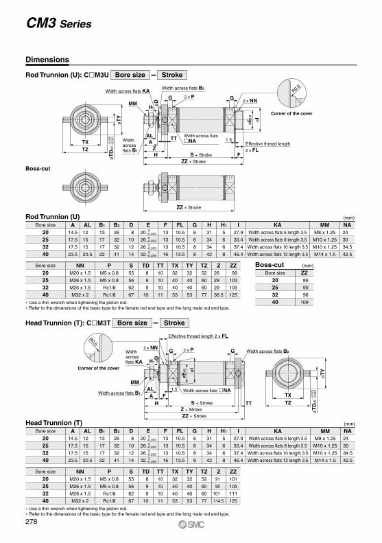
Rod Trunnion (U)Bore size
(mm)
20253240
A14.5
17.5
17.5
23.5
AL12
15
15
20.5
B1
13
17
17
22
B2
26
32
32
41
D 8
10
12
14
F13
13
13
16
FL10.5
10.5
10.5
13.5
G6
6
8
8
H31
34
34
42
H1
5
6
6
8
I27.9
33.4
37.4
46.4
KAWidth across flats 6 length 3.5
Width across flats 8 length 3.5
Width across flats 10 length 3.5
Width across flats 12 length 3.5
MMM8 x 1.25
M10 x 1.25
M10 x 1.25
M14 x 1.5
24
30
34.5
42.5
NA 0–0.033 0–0.033 0–0.033 0–0.039
E20
26
26
32
Bore size
20253240
NNM20 x 1.5
M26 x 1.5
M26 x 1.5
M32 x 2
PM5 x 0.8
M5 x 0.8
Rc1/8
Rc1/8
S55
56
62
67
TD 8
9
9
10
TT10
10
10
11
TX32
40
40
53
TY32
40
40
53
TZ52
60
60
77
Z26
29
29
36.5
ZZ 99
103
109
125
Boss-cutBore size
(mm)
20253240
ZZ 86
90
96
109
Head Trunnion (T)Bore size
(mm)
20253240
A14.5
17.5
17.5
23.5
AL12
15
15
20.5
B1
13
17
17
22
B2
26
32
32
41
D 8
10
12
14
F13
13
13
16
FL10.5
10.5
10.5
13.5
G6
6
8
8
H31
34
34
42
H1
5
6
6
8
I27.9
33.4
37.4
46.4
KAWidth across flats 6 length 3.5
Width across flats 8 length 3.5
Width across flats 10 length 3.5
Width across flats 12 length 3.5
MMM8 x 1.25
M10 x 1.25
M10 x 1.25
M14 x 1.5
NA24
30
34.5
42.5
Bore size
20253240
NNM20 x 1.5
M26 x 1.5
M26 x 1.5
M32 x 2
P S55
56
62
67
TD 8
9
9
10
TT10
10
10
11
TX32
40
40
53
TY32
40
40
53
TZ52
60
60
77
Z 91
95
101
114.5
ZZ101
105
111
125
0–0.033 0–0.033 0–0.033 0–0.039
E20
26
26
32
Boss-cut
∗ Use a thin wrench when tightening the piston rod.∗ Refer to the dimensions of the basic type for the female rod end type and the long male rod end type.
∗ Use a thin wrench when tightening the piston rod.∗ Refer to the dimensions of the basic type for the female rod end type and the long male rod end type.
Bore size StrokeRod Trunnion (U): CM3U
Bore size StrokeHead Trunnion (T): CM3T
M5 x 0.8
M5 x 0.8
Rc1/8
Rc1/8
CM3 Series
Dimensions
278
Corner of the cover
2 x P
2 x øLDNN
Width across flats KA
Width across flats B1
MM
+0.0580øCDH10
R0.5
NA
NA
øI
LV
0–0.1CX
LH
S + Stroke
FøD
1.5
Effective thread length FL
GG
H1
L RR
U
øC
I
LY
LF LGLT
LP
AL
A
H
Z + Stroke
ZZ + Stroke
LZ + Stroke
øE
h8
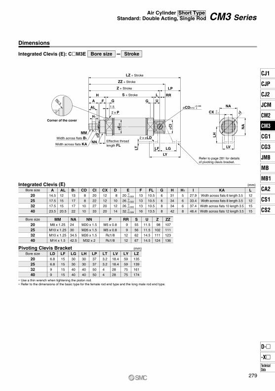
Integrated Clevis (E)Bore size
(mm)
20253240
A14.5
17.5
17.5
23.5
AL12
15
15
20.5
B1
13
17
17
22
CD 8
8
10
10
CI20
22
27
33
CX12
12
20
20
D 8
10
12
14
F13
13
13
16
FL10.5
10.5
10.5
13.5
G6
6
8
8
H31
34
34
42
H1
5
6
6
8
I27.9
33.4
37.4
46.4
KAWidth across flats 6 length 3.5
Width across flats 8 length 3.5
Width across flats 10 length 3.5
Width across flats 12 length 3.5
0–0.033 0–0.033 0–0.033 0–0.039
E20
26
26
32
Bore size
20253240
NA24
30
34.5
42.5
NNM20 x 1.5
M26 x 1.5
M26 x 1.5
M32 x 2
PM5 x 0.8
M5 x 0.8
Rc1/8
Rc1/8
RR 9
9
12
12
S55
56
62
67
U11.5
11.5
14.5
14.5
Z 98
102
111
124
ZZ107
111
123
136
Pivoting Clevis BracketBore size
(mm)
20253240
LD6.8
6.8
9
9
LF15
15
15
15
LG30
30
40
40
LH30
30
40
40
LP37
37
50
50
LT3.2
3.2
4
4
LV18.4
18.4
28
28
LY59
59
75
75
LZ135
139
161
174
Refer to page 281 for details of pivoting clevis bracket.
MMM8 x 1.25
M10 x 1.25
M10 x 1.25
M14 x 1.5
L12
12
15
15
∗ Use a thin wrench when tightening the piston rod.∗ Refer to the dimensions of the basic type for the female rod end type and the long male rod end type.
Retaining ring: Type C9 for axis Split pin: ø3 x 18 lRetaining ring: Type C9 for axis
∗ Retaining rings (split pins for ø40) are included. ∗ Retaining rings (split pins for ø40) are included.
Drill through
MM
A1 U1L1
øE
1
øND
øE
1
MM
A1
NX
R1
øND
R1
U1
L1
AA
NX
MM MM
A1 U1
L1
A
øE
1
øE
1
A1 U1
L1
A
R1 R1
NX
NZ L NX
NZ L
ø
2 x ø3Drill through
Split pin: ø3 x 18 l
CM3 Series
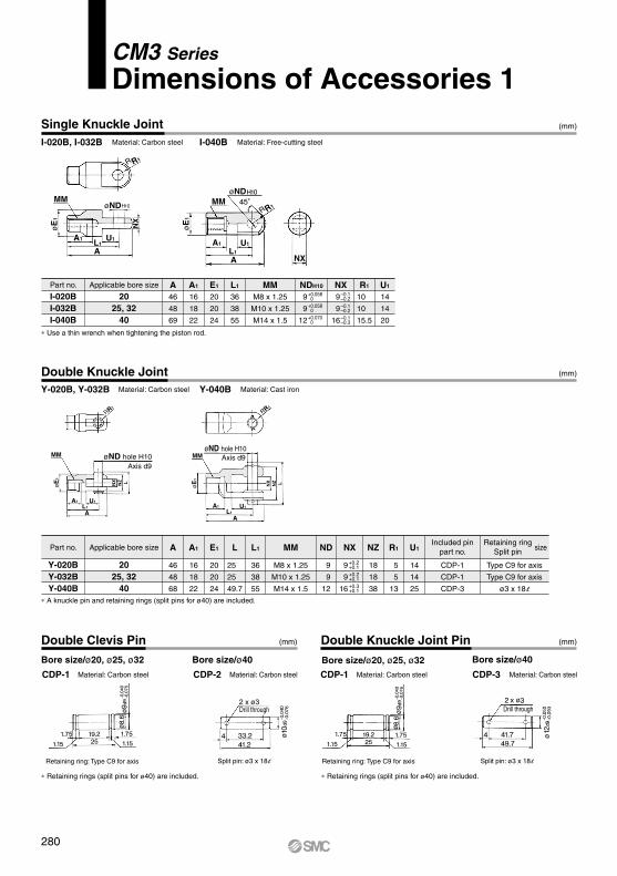
Dimensions of Accessories 1
280
øLD
LR
LG
LLVLX
LFLE
LY
LT L
H
øLC hole +0.15+0.05
Axis –0.040–0.076
L1
ød
m m
tt L
øD
øD
øC
H
B
d
C
B
d
øD
H
øD
HC
B
d
CM-E020BCM-E032B
20, 2532, 40
Applicablebore size
Part no.
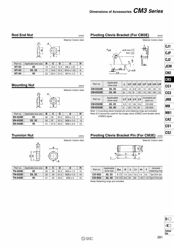
Rod End Nut (mm)
Trunnion Nut (mm)
Mounting Nut (mm)
Material: Carbon steel
Material: Carbon steel
Material: Carbon steel
Part no.
NT-02NT-03NT-04
Applicable bore size
2025, 32
40
B13
17
22
C15.0
19.6
25.4
D12.5
16.5
21.0
dM8 x 1.25
M10 x 1.25
M14 x 1.5
H5
6
8
Part no.
SN-020BSN-032BSN-040B
Applicable bore size
2025, 32
40
B26
32
41
C30
37
47.3
D25.5
31.5
40.5
dM20 x 1.5
M26 x 1.5
M32 x 2.0
H 8
8
10
Part no.
TN-020BTN-032BTN-040B
Applicable bore size
2025, 32
40
B26
32
41
C28
34
45
D25.5
31.5
40.5
dM20 x 1.5
M26 x 1.5
M32 x 2
H10
10
10
Pivoting Clevis Bracket (For CM3E) (mm)
Pivoting Clevis Bracket Pin (For CM3E) (mm)
Material: Carbon steel
Material: Carbon steel
CM-E020BCM-E032B
20, 2532, 40
Applicablebore size
Dd9
–0.040–0.076
8
10
–0.040–0.076
LD
6.8
9
LC
8
10
L
24.5
34
LE
22
25
LF
15
15
LG
30
40
Included pinpart no.
LH
30
40
LR
10
13
LT
3.2
4
LX
12
20
LY
59
75
LV
18.4
28
CD-S02
CD-S03
Part no.
CD-S02CD-S03
Applicablebore size
20, 2532, 40
d
7.6
9.6
L
24.5
34
L1
19.5
29
m
1.6
1.35
Note) Retaining rings are included.
t
0.9
1.15
Type C8 for axis
Type C10 for axis
Part no.
Includedretaining ring
Note 1) A pivoting clevis bracket pin and retaining rings are included.Note 2) It cannot be used for the single clevis (CM3C) and double clevis
(CM3D) types.
CM3 Series Dimensions of Accessories
281
CJ1
CJP
CJ2
JCM
CM2
CM3
CG1
CG3
MB
JMB
MB1
CA2
CS1
CS2
D-
-XTechnicalData
CM3
6.8 x 3.4
øTD
ø6.8
51 40 3.2
LXLZ
TX Z
7.5
20.5
40
57
tt
m m
ød
øD
d9
L
+0.15+0.05øCD
±0.2
17
25
ø6.8
7.5 40
R3.4
3.4
R3.4
6.8
57
28
3.2
5.2 40
R11
±0.2
17
25
ø6.8
7.540
R3.4
3.4
R3.4
6.8
+0.15+0.05øCD
5728
3.25.240
R11
L1
A°
ø6.8
6.8 x 3.4
øCDB°
90°
Z + Stroke
7.520.5
4057
5140
3.2
LXLZ
CX
ø6.8
6.8 x 3.4
øTDZ + Stroke
20.57.5 40
57
TX
LXLZ
3.2 40 51
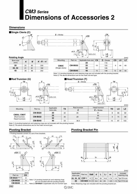
Pivoting Bracket Pivoting Bracket Pin
Single Clevis (C)
Rod Trunnion (U) Head Trunnion (T)
Rotating Angle
Note 1) A pivoting bracket pin and retaining rings are not included with the pivoting bracket.Note 2) The above dimensions are for the male rod end type.
A°+ B°+ 90°A°Bore size(mm)
2025, 32
40
25
21
26
B°
85
81
86
200
192
202
CDPart no.
CM-B020 Note 2)
CM-B032CM-B040
8
9
10
Mounting Part no. Applicable bore size Z + StrokeCX CD
CM3C(Single clevis)
CM-B032
CM-B040
116
120
126
148
20253240
10
15
9
10
LX
44
49
LZ
60
65
(mm)
Note 1) A pivoting bracket pin and retaining rings are not included with the pivoting bracket.Note 2) The above dimensions are for the male rod end type.
Note) Retaining rings are included with the pivoting bracket pin.
∗ Pivoting brackets consist of a set of two brackets.
Mounting Part no. Applicablebore size
Rod trunnion
ZTX TD
CM3U, CM3T(Rod trunnion,Head trunnion)
CM-B020
CM-B032
CM-B040
26
29
36.5
Head trunnion
Z + Stroke
91
95
101
114.5
20253240
32
40
53
8
9
10
LX
66
74
87
LZ
82
90
103
(mm)
(mm)(mm)
dPart no.Applicablebore size
Includedretaining ring
20, 25, 3240
CDP-1CD-S03
Type C9 for axis
Type C10 for axis
Dd9
9 –0.040–0.076
10 –0.040–0.076
8.6
9.6
L
25
34
L1
19.2
29
m
1.75
1.35
t
1.15
1.15Note 1) A pivoting bracket pin and retaining rings
are not included with the pivoting bracket.Note 2) CM-B020 is applicable only for trunnion type.
Dimensions
CM3 Series
Dimensions of Accessories 2
282
A
A
A
A≈Hs
22(24)
B
≈Hs
16
24.5(22)
B
≈Hs
16
20(22)
B
≈Hs
16
22 B
A B
≈Hs
16
≈Hs16
A B
≈Hs
24.5 A B
≈Hs
24.5 A B
≈Hs
A B
≈Hs
≈Hs
A B
A B
16
CM3 Series
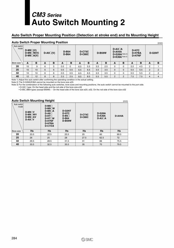
Auto Switch Mounting 1Auto Switch Proper Mounting Position (Detection at stroke end) and Its Mounting Height
Reed auto switchSolid state auto switch
( ): Dimension of the D-M9A.A and B are the dimensions from the end of the head cover/rod cover to the end of the auto switch.
( ): Dimension of the D-A96.A and B are the dimensions from the end of the head cover/rod cover to the end of the auto switch.
A and B are the dimensions from the end of the head cover/rod cover to the end of the auto switch.
( ): Dimension of the D-M9AV.A and B are the dimensions from the end of the head cover/rod cover to the end of the auto switch.
D-M9D-M9WD-M9A
D-M9VD-M9WVD-M9AV
D-H7/H7W/H7NF/H7BA/H7C
D-G5NT
D-G39A/K39A
D-A9
D-C7/C8/C73C/C80C
D-B5/B6/B59W
D-A33A/A34A
D-A44A
D-A9V
283
CJ1
CJP
CJ2
JCM
CM2
CM3
CG1
CG3
MB
JMB
MB1
CA2
CS1
CS2
D-
-XTechnicalData
CM3
20253240
Hs22.5
25
28.5
32.5
Hs25.5
28
31.5
35.5
Hs25
27.5
31
35
Hs60
62.5
66
70
Hs69.5
72
75.5
79.5
D-G5NTD-H7CD-B5D-B64D-B59W
D-G39AD-K39AD-A3A
D-C73CD-C80C D-A44A
Hs23.5
26
29.5
33.5
D-M9VD-M9WVD-M9AVD-A9V
D-M9D-M9WD-M9AD-A9D-H7D-H7WD-H7NFD-H7BAD-C7/C8
(mm)
A6.5
6.5
6.5
8.5
B5.5
6.5
6.5
8.5
A3.5
3.5
3.5
5.5
B2.5
3.5
3.5
5.5
A0
0
0
2
B0
0
0
2
A5.5
5.5
5.5
7.5
B4.5
5.5
5.5
7.5
A2
2
2
4
B1
2
2
4
D-C73CD-C80C
A0.5
0.5
0.5
2.5
B0
0.5
0.5
2.5
D-B54D-B64
A10
10
10
12
B 9
10
10
12
D-M9(V)D-M9W(V)D-M9A(V)
D-A9(V) D-B59WD-H7CD-H7BAD-H7NF
D-G5NT
A6
6
6
8
B5
6
6
8
D-A3AD-A44AD-G39A Note 2)
D-K39A Note 2)
(mm)
20253240
Auto Switch Proper Mounting Position (Detection at stroke end) and Its Mounting Height
Auto Switch Proper Mounting PositionAuto switch
model
Bore size
Auto switchmodel
Bore size
Auto Switch Mounting Height
Note 1) Adjust the auto switch after confirming the operating condition in the actual setting.Note 2) The D-G39A/K39A cannot be mounted on the bore size ø20.Note 3) For the combination of the following auto switches, bore sizes and mounting positions, the auto switch cannot be mounted to the port side. • D-G5 type: On the head side and the rod side of the bore size ø32 • D-B5/B64 types (except B59W) ··· On the head side of the bore size ø20, ø32, On the rod side of the bore size ø32
CM3 Series
Auto Switch Mounting 2
284
A 15
B
3.5
D-M9�
D-M9W
D-M9A
D-A9
D-M9V
D-A9V
5
10
10
5
5
5
10
5
10
15
10
15
20
20
20
25
15
20
15
20
20
25
30
25
30
35
55
55
60
50
35
25
35
60
70
80
70
75
110
20 + 35
(n = 2, 4, 6…)
(n – 2)2
55 + 35(n = 2, 3, 4, 5…)
(n – 2)
55 + 35(n = 2, 3, 4, 5…)
(n – 2)
60 + 35(n = 2, 3, 4, 5…)
(n – 2)
50 + 35(n = 2, 3, 4, 5…)
(n – 2)
35 + 35(n = 2, 3, 4, 5…)
(n – 2)
25 + 35(n = 2, 3, 4, 5…)
(n – 2)
35 + 35(n = 2, 3, 4, 5…)
(n – 2)
60 + 45(n = 2, 3, 4, 5…)
(n – 2)
70 + 45(n = 2, 3, 4, 5…)
(n – 2)
80 + 50(n = 2, 3, 4, 5…)
(n – 2)
70 + 50(n = 2, 3, 4, 5…)
(n – 2)
75 + 50(n = 2, 3, 4, 5…)
(n – 2)
110 + 100(n = 2, 3, 4, 5…)
(n – 2)
20 + 35
(n = 2, 4, 6…)
(n – 2)2
25 + 35
(n = 2, 4, 6…)
(n – 2)2
15 + 35
(n = 2, 4, 6…)
(n – 2)2
20 + 35
(n = 2, 4, 6…)
(n – 2)2
15 + 35
(n = 2, 4, 6…)
(n – 2)2
20 + 35
(n = 2, 4, 6…)
(n – 2)2
20 + 45
(n = 2, 4, 6…)
(n – 2)2
30 + 50
(n = 2, 4, 6…)
(n – 2)2
25 + 50
(n = 2, 4, 6…)
(n – 2)2
30 + 50
(n = 2, 4, 6…)
(n – 2)2
35 + 30
(n = 2, 4, 6…)
(n – 2)2
25 + 45
(n = 2, 4, 6…)
(n – 2)2
D-M9D-M9WD-M9AD-A9
D-M9WVD-M9AV
D-C7D-C80
D-H7D-H7WD-H7BAD-H7NF
D-C73CD-C80CD-H7C
D-B5D-B64D-G5D-K59
D-B59W
D-A3AD-G39AD-K39AD-A44A
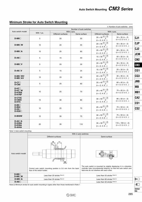
Minimum Stroke for Auto Switch Mounting
Auto Switch Mounting CM3 Series
n: Number of auto switches (mm)
Auto switch modelWith 1 pc.
With 2 pcs.Different surfaces
With n pcs.Number of auto switches
Same surface Same surfaceDifferent surfaces
With 2 auto switches
Different surfaces Same surface
Note 1) Auto switch mounting
Auto switch model
Note 2) Minimum stroke for auto switch mounting in types other than those mentioned in Note 1
The auto switch is mounted by slightly displacing it in a direction (cylinder tube circumferential exterior) so that the auto switch and lead wire do not interfere with each other.
Correct auto switch mounting position is 3.5 mm from the back face of the switch holder.
∗ Values which include hysteresis are for guideline purposes only, they are not a guarantee (assuming approximately ±30% dispersion) and may change substantially depending on the ambient environment.
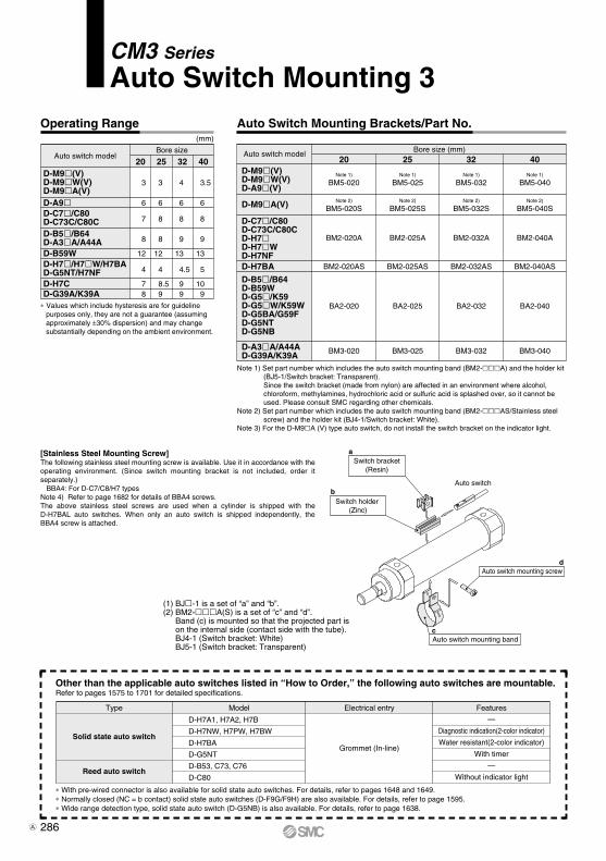
Auto Switch Mounting Brackets/Part No.
Note 1) Set part number which includes the auto switch mounting band (BM2-A) and the holder kit (BJ5-1/Switch bracket: Transparent).Since the switch bracket (made from nylon) are affected in an environment where alcohol, chloroform, methylamines, hydrochloric acid or sulfuric acid is splashed over, so it cannot be used. Please consult SMC regarding other chemicals.
Note 2) Set part number which includes the auto switch mounting band (BM2-AS/Stainless steel screw) and the holder kit (BJ4-1/Switch bracket: White).
Note 3) For the D-M9A (V) type auto switch, do not install the switch bracket on the indicator light.
[Stainless Steel Mounting Screw]The following stainless steel mounting screw is available. Use it in accordance with the operating environment. (Since switch mounting bracket is not included, order it separately.) BBA4: For D-C7/C8/H7 typesNote 4) Refer to page 1682 for details of BBA4 screws.The above stainless steel screws are used when a cylinder is shipped with the D-H7BAL auto switches. When only an auto switch is shipped independently, the BBA4 screw is attached.
(1) BJ-1 is a set of “a” and “b”.(2) BM2-A(S) is a set of “c” and “d”.
Band (c) is mounted so that the projected part is on the internal side (contact side with the tube).BJ4-1 (Switch bracket: White)BJ5-1 (Switch bracket: Transparent)
∗ With pre-wired connector is also available for solid state auto switches. For details, refer to pages 1648 and 1649.∗ Normally closed (NC = b contact) solid state auto switches (D-F9G/F9H) are also available. For details, refer to page 1595.∗ Wide range detection type, solid state auto switch (D-G5NB) is also available. For details, refer to page 1638.
Other than the applicable auto switches listed in “How to Order,” the following auto switches are mountable.Refer to pages 1575 to 1701 for detailed specifications.