CompactDAQ System Build GuideThe CompactDAQ system is ideal for medium-channel-count DAQ applications that require accurate measurements from multiple sensors, signals,
and networks. This guide includes a comprehensive list of components and considerations to successfully deploy a CompactDAQ system and
meet your application requirements.
ni.com/compactdaq
Table of ContentsNI Components for CompactDAQ Systems ........3
Assembling Your CompactDAQ Hardware ................................4Chassis and Controller Options .............................................4Module Options .....................................................................4Out-of-Box Hardware Experience ..........................................5
Sensor Connectivity .................................................................6
Communication ........................................................................7
Synchronizing Your Signals .......................................................8Hardware Synchronization .....................................................8Synchronization Programming Experience ............................8
Maintaining Your CompactDAQ System ...................................9Calibration ..............................................................................9Repair Services ....................................................................10
Completing Your CompactDAQ Systems ....... 11
Powering Your System .......................................................12Desktop or Industrial Power Supply ................................12Battery-Powered Operation ............................................12Redundant Power Supplies .............................................12
Grounding and Isolation .....................................................13Isolation ..........................................................................13Field Wiring Guide ..........................................................13
Wireless Communication ..................................................14
HMI and User Interfaces ...................................................15
Enclosures .........................................................................16Choosing an Enclosure ...................................................16Sizes and Clearances ......................................................16
Mounting ...........................................................................17Desktop Mount ...............................................................17DIN Rail Mount ...............................................................17Panel Mount ...................................................................18Rack Mount ....................................................................18
Next Steps and Additional Resources ...............................19
How to Use This Guide
W
D EP
AAdvisor: Turn your application specifications into
a valid solution and list of products.
White Paper: Read technical content that focuses
on a specific topic area.
Web Site: Explore varied resources hosted
on ni.com.
Video: Watch technical demonstrations to further
understand the content addressed.
PDF Document: Review detailed information
on a printable, wed hosted PDF document.
MUser Manual: Read the in-depth product manual
or user guide for the hardware you are considering.
Engineer: Speak to an NI engineer about your
system requirements.
V
ni.com/compactdaq
* To enjoy the full functionality of this interactive PDF, download and make sure the latest version of Acrobat Reader is installed.
ni.com/compactdaq | 3
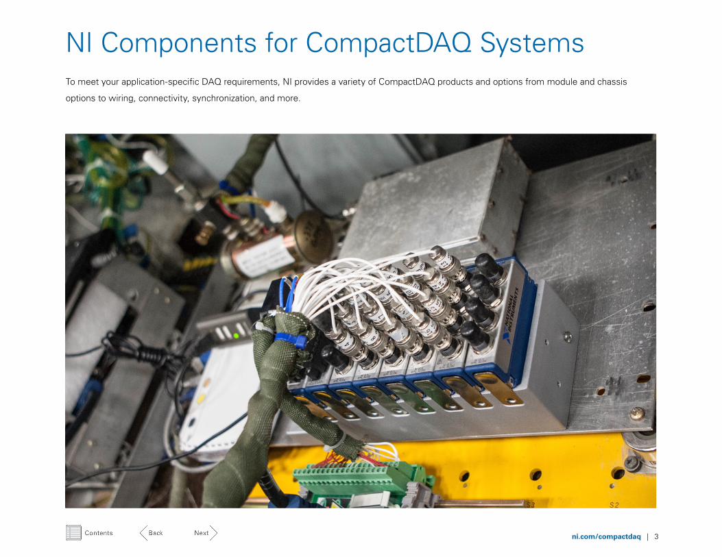
NI Components for CompactDAQ SystemsTo meet your application-specific DAQ requirements, NI provides a variety of CompactDAQ products and options from module and chassis
options to wiring, connectivity, synchronization, and more.
ni.com/compactdaq | 4
Chassis and Controller Options CompactDAQ chassis control the timing, synchronization, and data transfer between the modules and an external or
built-in computer. The I/O modules and the programming experience are common between all CompactDAQ chassis
options, so you can change your system deployment without reinvesting in other parts of your design.
CompactDAQ features a variety of connectivity and module capacity options:
Connectivity Module Capacity
USB 1, 4, or 8
Ethernet 1, 4, or 8
802.11 (wireless) 1
Processor Module Capacity
1.33 GHz dual-core Intel Atom 4 or 8
1.06 GHz dual-core Intel Celeron 8
1.33 GHz dual-core Intel i7 8
Chassis Controller
Module OptionsBy specifying your module mix to include exactly the right combination of signal conditioned I/O, you can ensure
accurate measurements and direct sensor connectivity without the lengthy process of custom design or expensive
pure-universal options.
CompactDAQ is compatible with over 60 I/O modules for the sensor and signal types listed below:
Analog Input § Voltage
§ Current
§ Universal
§ Thermocouple
§ RTD
§ Strain/bridge based
§ Acceleration and sound
Analog Output § Voltage
§ Current
Digital I/O § Input
§ Output
§ Input/output
§ Relays
Bus § CAN
§ LIN
Assembling Your CompactDAQ Hardware
ni.com/compactdaq | 5
Install NI-DAQmx driver onto computer
or controller
INSTALL
Out-of-Box Hardware Setup ExperienceGetting to your first measurement using CompactDAQ is a straightforward process. The form factor you choose for
your application can produce slight process variations, but, in general, the configuration for any device that uses the
NI-DAQmx driver follows the same simple steps.
Open configuration tool and select desired chassis from auto-
detected list
View raw data within the configuration tool test panels to confirm expected connectivity
Wi-Fi and Ethernet only: Reserve chassis from
other network users and specify the IP address
Program measurement functionality to acquire, analyze, visualize, and
manage your data as needed
CONFIGURE RESERVE TEST MEASURE
Physically connect the power supply,
communication bus, chassis, modules,
and sensors
CONNECT
USB SystemsCompactDAQ USB chassis provide the
plug-and-play simplicity of USB to sensor
and electrical measurements. Watch this
introductory video to learn how to set
up your system, from unpacking your
hardware and software to taking your
first measurement.
Ethernet SystemsTo make networking more accessible to
the non-IT professional, CompactDAQ
Ethernet chassis use the zero configuration
networking (zeroconf) standard. Watch
this introductory video to walk through
the setup process.
Wireless SystemsWith simple network configuration and
802.11 WiFi connectivity, CompactDAQ
wireless chassis make it easier than ever
to take your measurement system to the
sensor. Watch this introductory video for
the step-by-step setup process.
Integrated ControllersCompactDAQ controllers integrate
processing with the option to run
Windows Embedded Standard 7 or a
real-time OS preloaded with the required
software for configuration and setup.
Watch this introductory video to see
the setup process for each option.
ni.com/compactdaq | 6
Sensor Connectivity You have a lot of different options when it comes to choosing your connectivity. Choosing between a BNC, D-SUB, screw terminal, RJ50, LEMO,
spring terminals, and other connectivity options to achieve the best performance can be difficult. Your measurement type requirements, the
locking mechanism you need, the ruggedness of the connector, and the ease of connection/disconnection help you determine the appropriate
connector for your application.
BNCThis miniature quick connect/disconnect connector
features two pins and ensures a high-quality connection
with just a quarter turn of the coupling nut. It is ideal for
single-ended measurements. Since the BNC connector
has two pins, it doesn’t provide a true differential
measurement, which requires three pins.
D-SUBSurrounded by a D-shaped metal to ensure the correct
connection orientation, a D-SUB connector contains
two or more parallel rows of pins or sockets. Its many
different sizes are denoted by the number of positions;
for example, the DB-25 denotes 25 positions. Widely
used for serial communication, the D-SUB connector
also works for a variety of measurements because of
the available positions.
Screw TerminalThe wire from the sensor is held by the tightening of a
screw in this connector, which offers so many different
implementation possibilities that it has become one
of the most common connectors. However, a screw
terminal connector doesn’t provide a quick connect/
disconnect solution, so it can be tedious in higher
channel count applications.
RJ50Similar to the RJ45 except that it uses one more pair
of signal wires for a total of 10, the RJ50 connector
provides a quick and secure connect/disconnect
from CompactDAQ, which is ideal for bridge-based
measurements. It can measure Transducer Electronic
Data Sheets (TEDS).
LEMOThis push/pull connector works with several connector
standards to offer high-quality connections with a variety
of options so you can achieve high measurement quality.
Spring TerminalsA spring mechanism located inside this connector allows
a user to quickly and easily connect bare wires from the
sensor simply by compressing the spring with a small
screwdriver, inserting the wire and then releasing to
lock. Ideal for low channel count, often reconfigured
applications, spring connectors can be tedious in higher
channel count use cases as they do not provide a quick
multi channel connect/disconnect solution.
ni.com/compactdaq | 7
WirelessWireless is also useful for remote and distributed measurements for which cabling
is expensive or impractical, such as structural health monitoring for bridges. Wi-Fi
communication using the IEEE 802.11 protocol is widely available and easy to set up by
connecting to a hotspot or access point. Wireless has the highest latency of any DAQ
bus, so avoid using it with applications that need high-speed control and determinism.
Refer to the wireless communication section for more information on other types of
wireless communication such as cellular and satellite.
USBUSB is practical for portable measurements and convenient because connectivity is
easy and ubiquitous. After software drivers are installed, the host automatically detects
USB devices, which eliminates the need for manual configuration to discover the
devices. A USB controller can connect to multiple devices that share a maximum
theoretical bandwidth of 60 MB/s under the USB 2.0 standard. Although easy to use,
USB devices are not recommended for closed-loop control applications because the
bus is inherently latent and nondeterministic.
EthernetEthernet is ideal for remote and distributed measurements, particularly those that
extend beyond the reach of a 5 m USB cable. In addition to enabling direct connection
to your laptop or PC, Ethernet provides widely available ports throughout offices,
labs, and manufacturing facilities to offer additional accessibility options for multiple
users. Network bandwidth varies based on the number of other devices connected
to the network.
CommunicationCompactDAQ systems communicate over USB, Ethernet, and wireless buses or are designed as independent controller-based devices. Each
bus has different advantages and disadvantages, including trade-offs between bandwidth, latency, ease of synchronization, portability, and
measurement distance from a host.
Stand-AloneUsing a CompactDAQ controller can be beneficial for applications that are remote or
mobile such as environmental monitoring or in-vehicle data logging. To run completely
independent, CompactDAQ controllers include embedded processing and onboard
storage, which eliminates the need for an external PC. Running either a Windows
Embedded Standard 7 (WES7) or the LabVIEW Real-Time OS you can run all your
measurement, analysis, and logging software, as well as any additional software
supported by your choice of OS, directly on the device. There is an additional
advantage to integrating the entire signal chain into a single rugged system; the points
of failure and sources of error are reduced, this makes CompactDAQ controllers
a highly reliable option to collecting important data sets.
ni.com/compactdaq | 8
Hardware SynchronizationA CompactDAQ system features three main types of hardware synchronization:
Synchronizing Your Signals When CompactDAQ applications require precise time correlation between measurement channels, modules, or even chassis, a combination
of hardware and the NI-DAQmx API ensures tight synchronization.
The NI-DAQmx driver automatically handles the synchronization of channels across one or multiple chassis as long
as all channels in the task are of the same I/O type. This simplifies your code by making it straightforward to write,
debug, and understand.
By connecting multiple CompactDAQ systems using the NI 9469 synchronization module, you can include channels
from multiple C Series I/O modules within separate CompactDAQ chassis in the same task, and the NI-DAQmx driver
then takes care of the synchronization. The NI 9469 offers synchronization to SAR, Slow-Sampled, Delta Sigma, digital
input and output, and analog output modules in differing chassis topologies.
Single Module: Most CompactDAQ modules have a
simultaneous architecture that ensures the tight phase
synchronization of data, which is then automatically
synchronized within your task.
Multi-Module: CompactDAQ chassis contain seven
distinct timing engines specified as 3 x AI, AO, DI, DO, and
counters. With these options, you can easily synchronize
multiple modules of different types at the same or
different sample rates.
Multi-Chassis: You can synchronize channels across
any number of chassis into a single task when you link
chassis together by slotting in synchronization modules.
Synchronization Programming Experience
Reference to All Channels
Synchronized Reference to Task Input
Synchronized “Reference Wire”Chassis 1, I/O Channels Chassis 2, I/O Channels
Function Diagram LabVIEW G Code
ni.com/compactdaq | 9
CalibrationElectronic components naturally drift over time, which
can cause uncertainty in your measurements. To have
confidence in the data you publish and to meet the often
strict regulations of the industry you work in, NI provides
customized calibration options.
Traceable Calibration
Compliant Calibration
ISO 17025 Accredited Calibration
Additional Calibration
Services
Verification and adjustment of measurement performance using calibration procedures approved by NI
• • • •
Detailed measurement data for all applicable channels
• • • •
Availability at point of sale • • • •
Calibration performed at ISO 17025 accredited laboratory
– • • •
Evaluation of measurement uncertainty – • • •
Calculated expanded measurement uncertainty
– – • •
Advanced services—system calibration, on-site calibration, and more
– – – •
Maintaining Your CompactDAQ SystemOften the maintenance of a DAQ system is considered only when a component fails or a result is inaccurate. By planning ahead for repairs,
component replacements, and calibration, you can maintain system accuracy with minimum downtime.
ni.com/compactdaq | 10
Repair ServicesThough you may never need to repair your hardware, NI offers repair services for unexpected breakdowns. Highly trained
factory technicians perform these services in a timely manner using only original parts at one of the NI service centers.
When time is at a premium, you can choose one of NI’s several repair options to expedite your repair. In addition,
NI provides advanced options to give you more information about the nature of the repair. These additional service
upgrades including the following:
§ Next-on-bench: Move your product to the front of the line by purchasing this expedited service upgrade.
§ Advanced replacement: Minimize application downtime with this service. NI ships a replacement immediately so
you get a working product as fast as possible, which can save you 10 days of downtime. The advanced replacement
service is available only via an NI Service Program.
§ Detailed repair report: Get a better understanding of what went wrong with more details about the
component failure.
ni.com/compactdaq | 11
Completing Your CompactDAQ SystemA DAQ system consists of more than just the DAQ hardware. You often need peripheral components like batteries, Wi-Fi routers, touch screens,
and enclosures to complete your system. This section examines how to complete your system to meet your application-specific requirements.
ni.com/compactdaq | 12
Powering Your SystemDesktop or Industrial Power SupplyMost applications feature access to grid power. However, your application’s environment determines which type of power supply you should select.
Desktop Power Supply: Used in a desktop or lab setting, a desktop power supply provides an economical, compact, and reliable power solution.
Industrial Power Supply: Recommended for applications deployed into industrial environments, such as factory floors, these power supplies provide a long expected life,
generous power reserves, and reliable operation in harsh conditions.
Battery-Powered OperationTo properly choose a battery for your CompactDAQ system, either as a primary or secondary (back-up) supply, you need to answer three questions:
Do you need a single-use or rechargeable option?
How long does the system need to run on battery power?
What are your current and future budgets for batteries?
CompactDAQ requires 9 VDC to 30 VDC power to operate, so Alkaline, NiMH, and Li-Ion batteries are all viable options and have been deployed successfully. No one battery pack
can solve every remote or portable power application. With some planning, however, you can choose a custom battery solution for your DAQ applications.
Redundant Power SuppliesMost applications do not require redundancy, but if the cost of failure is high enough, you may consider adding it. When using CompactDAQ systems with an onboard controller,
you can implement dual power supplies. V1 (usually mains) operates in normal running conditions, but if this supply drops below 9 V in a blackout or brownout situation, the
CompactDAQ system automatically and seamlessly switches to its auxiliary power supply (V2), which is often a battery. You can use this to ensure continued operation through
short-term power outages or to implement safe shutdown procedures with no loss of data.
ni.com/compactdaq | 13
Field Wiring and Grounding
InputConfiguration
Signal Source Type
Floating Signal Source(Not Connected toBuilding Ground)
Examples Thermocouples Signal Conditioning with Isolated Ouputs Battery Devices
Examples Plug-in Instruments with Nonisolated Inputs
Grounded Signal Source
Differential(DIFF)
Single-Ended-GroundReferenced(RSE)
Single-Ended-Nonreferenced(RSE)
AI (+)
AI (–)
AI GND
AI (+)
AI (–)
AI GND
AI
AI GND
AI
AI GND
V1
R R
V1
V1
V1 V1
V1
Vg
AI
AI SENSE
AI GND
AI
AI SENSE
R
R
AI GND
Two resistors (10kΩ<R<100 kΩ)provide retun pathsto ground for bias currents
Groud-loop losses, Vg, are addedto measured signal
NOT RECCOMENDED
Isolation
Signal Integrity and AccuracyFor a nonisolated instrument, the local ground is the system/earth ground, so the
instrument’s input range is in a window around earth ground. However, an instrument
with channel-to-earth isolation has a measurement range in a window around its
isolated-local ground, which can float at a much different voltage than earth ground.
This can allow the measurement of several tiny millivolt signals such as thermocouples,
each sitting at its own unique common-mode voltage.
system as common-mode voltage. One drawback is you
need twice the number of input channels as signals in
your DAQ system. You can reduce channel requirements
by adopting a nonreferenced single-ended (NRSE)
architecture for which all channels are measured with
respect to a single node usually labeled as AI Sense.
You must provide bias resistors when measuring floating
signal sources in DIFF and NRSE configurations. Failure
to do so results in erratic or saturated (positive full-scale
or negative full-scale) readings.
Find more information on grounding architectures along
with details on minimizing noise and balancing your
system in the NI field wiring guide.
Safety and Instrument ProtectionCompactDAQ modules are independently certified to be safe when used within
specifications. Most modules feature hazardous location certifications and/or isolation.
Each module is categorized into NI-defined isolation levels:
§ 60 VDC continuous/1,000 Vrms withstand
§ 250 Vrms continuous/2,300 Vrms withstand
§ 300 Vrms continuous/2,300 Vrms withstand
Measuring analog signals is not always as simple
as wiring the signal source leads to the DAQ device.
Knowing the nature of the signal source and relevant
grounding configurations is required to produce accurate
and noise-free measurements.
Signal sources are broadly classified into two types:
§ Grounded or ground-referenced signal source
§ Ungrounded or nonreferenced (floating) signal source
A grounded signal source is best measured with a
differential or nonreferenced measurement system.
In a differential architecture, neither of the inputs is tied
to a fixed reference such as earth or building ground. This
is useful in rejecting noise including the unwanted noise
often introduced in the circuit that makes up the cabling
Grounding and Isolation
ni.com/compactdaq | 14
Types of Wireless
Cellular communication uses infrastructure provided by wireless
service companies to allow high-bandwidth data to be transmitted
from anywhere there is cellular service. This often comes at a high
price, though, especially when dealing with data plans.
Wi-Fi, the most common wireless standard, is readily available in both
consumer and industrial-grade routers. It offers the highest bandwidth
and cheapest cost, but it generally requires you to build your own
infrastructure and limits you to a few hundred meters.
900 MHz radios are limited to the United States, but they offer
long-range, low-bandwidth communication over existing infrastructure.
This technology is a low-cost way to transmit small amounts of data
over long distances in remote locations.
Wireless CommunicationsMany applications require wireless communication to remotely access a DAQ system, whether for upgrading software, changing configuration
parameters, or streaming, downloading, or viewing data. If your system is installed in a remote location or if you simply want to reduce physical
wiring for cost, noise, or aesthetic reasons, you can choose from several wireless standards such as Wi-Fi, 900 MHz, cellular, and satellite. But
each of these standards involves trade-offs, including bandwidth, availability, cost, distance, and reliability, that you need to consider during your
selection process.
Satellite communication is the most expensive option, but it can offer
data transmission from virtually anywhere on the planet. You can achieve
high bandwidth if you are willing to pay for it, but you are susceptible to
rain fade bandwidth loss when there is significant moisture in the air.
ni.com/compactdaq | 15
User Interfaces and HMIsFor the first configuration, you can wire a traditional
display or HMI directly to a CompactDAQ controller
that is running a LabVIEW application and use the user
interface or front panel within the LabVIEW application
as your user interface. For the second configuration,
you can create a LabVIEW application to run on the host
PC/IPC/laptop and use the user interface or front panel
within the application as the user interface.
When you need to build a user interface or integrate
a human machine interface (HMI) in a CompactDAQ
system, you have several options. Two primary
configurations for CompactDAQ systems are:
1. A CompactDAQ controller with an embedded
PC that you can directly connect to an HMI
2. A USB or Ethernet chassis wired to a host
PC/IPC/laptop
Configuration 1. CompactDAQ Controller Directly Connected
to a Local HMI or Display
Configuration 2. USB or Ethernet CompactDAQ Chassis
Connected to a Host PC/Laptop Running a LabVIEW Application
Additionally, with both configurations, if you need a remote
HMI to connect to your CompactDAQ system, you can
use the Data Dashboard for LabVIEW. With it, you can
create a custom dashboard on iPads or Android tablets
to interact with any networked LabVIEW-based system.
ni.com/compactdaq | 16
Choosing an EnclosureKeep in mind the below considerations when choosing and installing an enclosure.
§ Enclosure materials such as metals, plastics, and polymers have different insulating, structural integrity, and
flammability properties, so you need to account for your CompactDAQ system’s environment when selecting
your enclosure.
§ When choosing the size, be mindful of the clearance requirements of your CompactDAQ chassis, including the
modules with backshell connectors installed.
§ You can pass signal and communication wires in and out of the enclosure through glands, which is faster but often
permanent. Bulkhead connectors offer a more flexible way to send signals in and out of the enclosure.
§ Enclosures can include both heating elements for cold environments and cooling systems like Peltier plates or split
system air conditioners for hot environments. For less extreme environments, you can directly attach a simple heat
sink to the back of the CompactDAQ system to remove heat from the enclosure.
Sizes and ClearancesTo properly choose an enclosure size, you need to know both the sizes and clearances of the equipment you plan to
install in the enclosure. Clearance requirements are often mistakenly ignored. This limits the proper airflow around the
equipment and derates the temperatures or accuracies your DAQ system can operate to.
To ensure you are properly choosing and laying out your enclosure, reference your CompactDAQ documentation or the
dimensional drawings.
EnclosuresEnclosures can help protect your hardware from exposure to harsh environmental conditions such as extreme temperatures, dirt, dust, water,
or soot. Unfortunately, choosing a sealed metal box and mounting the hardware in it can be difficult. You need to consider self-heating from the
hardware, airflow, cable management, heating and cooling, connectivity in and out of the enclosure, and clearspace requirements to ensure the
hardware performs to its specifications.
ni.com/compactdaq | 17
Desktop MountUse the desktop mount kit for easy access to modules
for interactive desk or lab use. This is available for all
multislot chassis and controller variations.
DIN Rail MountUse the DIN rail mount kit to attach your CompactDAQ
system to any standard 35 mm DIN rail.
MountingCompactDAQ systems feature built-in mounting holes you can use to secure the hardware in place. Mounting provides convenient and secure
placement, but it also can affect the measurement quality of your DAQ system. Different mounting configurations can reduce the maximum
ambient temperature under which you can maintain the typical accuracy of certain I/O modules.
ni.com/compactdaq | 18
Rack MountUse the rack mount kit to install your CompactDAQ
system into a standard 19 in. rack. You can place the
chassis or controller in an enclosure that slides into the
rack or attach the hardware without an enclosure to DIN
rails that slide along the side rails of the rack.
Panel MountUse the panel mount kit to securely mount your
CompactDAQ system to a wall or flat surface.
Panel mounting is recommended for high shock
and vibration applications.
ni.com/compactdaq | 19
Next Steps and Additional ResourcesEach unique application will have individual specifications, needs and deployment requirements. For assistance
configuring a system or to ask further questions about how to ensure CompactDAQ meets your exact requirements,
please contact one of our engineers.
Speak to an NI Engineer about your system requirements Map your specifications document to NI hardware and software options.
Configure a Complete CompactDAQ System with the Online Product Advisor Walk through selecting I/O modules and chassis based on your measurement needs.
Already have an idea of which CompactDAQ products will meet your application needs?Review the CompactDAQ user manuals for an in-depth study of product features, analog & digital timing specifications,
counters, and environmental requirements.