70
Compal Broadband Networks CH6640E/CG6640E Wireless Gateway Series User Guide
Compal Broadband Networks
CH6640E/CG6640E Wireless Gateway Series
User Guide
ii
Table of Contents
Overview Contact Information...............................................................................................................1 Standard Features ................................................................................................................1 CH6640E/CG6640E LAN Choices.........................................................................................2
Wireless LAN..................................................................................................................2 Wired Ethernet LAN........................................................................................................4
Front Panel ...........................................................................................................................5 Rear Panel............................................................................................................................7 MAC Label ............................................................................................................................8
Getting Started Inside the Box ..................................................................................................................... 10 Before You Begin................................................................................................................ 11
System Requirements................................................................................................... 11 Connecting the CH6640E/CG6640E ................................................................................... 12 Wall Mounting the CH6640E/CG6640E ............................................................................... 14
Wall Mounting Template ............................................................................................... 16 Setting Up Internet Access.................................................................................................. 16
Configuring TCP/IP in Windows XP............................................................................... 17 Configuring TCP/IP in Windows Vista ........................................................................... 17 Verifying the IP Address in Windows XP ....................................................................... 17 Verifying the IP Address in Windows Vista .................................................................... 18 Renewing Your IP Address ........................................................................................... 18
Setting Up a Wi-Fi Network ................................................................................................. 18
Basic Configuration Starting the CH6640E/CG6640E Configuration Manager (CMGR)....................................... 19 CH6640E/CG6640E Menu Options Bar............................................................................... 20
CABLE MODEM Pages CABLE MODEM Status Page ............................................................................................. 21 CABLE MODEM Signals Page ............................................................................................ 22 CABLE MODEM Logs Page................................................................................................ 23 CABLE MODEM Addresses Page....................................................................................... 23 CABLE MODEM Configuration Page................................................................................... 24 CABLE MODEM Provisioning Page .................................................................................... 25
GATEWAY Basic Pages Basic Setup Page ............................................................................................................... 26 Basic DHCP Page............................................................................................................... 29 Basic LAN Users Page........................................................................................................ 30
GATEWAY Advanced Pages Advanced Options Page...................................................................................................... 31 Advanced IP Filtering Page ................................................................................................. 32 Advanced MAC Filtering Page............................................................................................. 32
Setting a MAC Address Filter ........................................................................................ 33
iii
Advanced Port Filtering Page.............................................................................................. 33 Advanced Port Forwarding Page......................................................................................... 34 Advanced Port Triggers Page ............................................................................................. 36 Advanced DMZ Host Page.................................................................................................. 37
Setting Up the DMZ Host .............................................................................................. 37 Dynamic DNS ..................................................................................................................... 37 Advanced IDS Page............................................................................................................ 38
GATEWAY Wireless Pages Wireless Band Mode Page.................................................................................................. 40 Wireless Basic Page ........................................................................................................... 40 Wireless Security Page ....................................................................................................... 42 Wireless WPS Page............................................................................................................ 47 Wireless Access Control Page ............................................................................................ 48 Wireless Status Page.......................................................................................................... 50 Setting Up Your Wireless LAN............................................................................................. 50
Encrypting Wireless LAN Transmissions ....................................................................... 51
GATEWAY USB Pages Print Server .................................................................................................................. 52 FTP Server ................................................................................................................... 53 File Server .................................................................................................................... 54
GATEWAY MANAGEMENT Pages Remote Management Control ............................................................................................. 55 Loopback IP........................................................................................................................ 55
TELEPHONE Pages TELEPHONE Status Page .................................................................................................. 57 TELEPHONE Call Page ...................................................................................................... 58
Call Status Tab ............................................................................................................. 58 Quality Of Service Tab.................................................................................................. 58
TELEPHONE Logs Page .................................................................................................... 59 Telephone Log Tab....................................................................................................... 59 Call Signaling Log Tab.................................................................................................. 59
TELEPHONE Provisioning Page ......................................................................................... 61 Setup Tab..................................................................................................................... 61 Line Tab ....................................................................................................................... 61 Call Features Tab ......................................................................................................... 62 Errors Tab .................................................................................................................... 62
TELEPHONE Configuration Page ....................................................................................... 63
HELP Pages HELP Cable Modem Page .................................................................................................. 64 HELP Telephone Page ....................................................................................................... 64
Troubleshooting Solutions............................................................................................................................. 66 Front-Panel LEDs and Error Conditions............................................................................... 67
1
1 Overview
The CBN CH6640E/CG6640E Wireless Gateway is designed for your home, home office, or small business/enterprise. It can be used in households with one or more computers capable of wireless connectivity for remote access to the wireless gateway.
This user guide provides product overview and setup information for the CH6640E/CG6640E. It also provides instructions for installing the wireless gateway and configuring the wireless LAN, Ethernet, router, DHCP, and security settings.
Note: For the following VoIP function content, only applicable to CH6640E Cable Modem Voice Gateway.
Contact Information
• For any questions or assistance with the CH6640E/CG6640E Wireless Gateway, contact your Internet Service provider.
• For information on customer service, technical support, or warranty claims; see the CBN CH6640E/CG6640E Software License, Warranty, Safety, and Regulatory Information card provided with the CH6640E/CG6640E Wireless Gateway.
Standard Features
The CH6640E/CG6640E Wireless Gateway combines high-speed Internet access, networking, and computer security for a home or small-office LAN. It offers the following features:
• Combination of five separate products in one compact unit — an EURO DOCSIS® 3.0 cable modem, IEEE 802.11b/g/n wireless access point, Ethernet 10/100/1000 Base-T connections, two VoIP Internet telephone connections, and firewall.
• An integrated high-speed cable modem for continuous broadband access to the Internet and other online services with much faster data transfer than traditional dial-up or ISDN modems.
• Advanced firewall for enhanced network security from undesired attacks over the Internet. It supports stateful-inspection, intrusion detection, DMZ, denial-of-service attack prevention, and Network Address Translation (NAT).
• One broadband connection for up to 253 computers to surf the web; all computers on the LAN communicate as if they were connected to the same physical network.
• Four 10/100/1000Base-T Ethernet uplink ports supporting half- or full-duplex connections with auto-MDIX capability.
• An IEEE 802.11n wireless access point to enable laptop users to remain connected while moving around the home or small office or to connect desktop computers without installing network wiring. Depending on distance, wireless connection speeds can vary.
2
• CH6640E/CG6640E wireless function supports Wi-Fi 2.4G single-band mode.
• A secure Wireless Fidelity (Wi-Fi) broadband connection for Wi-Fi enabled devices on your network, such as your cellular telephone, laptops, printers, PDAs, and desktops.
• Routing for a wireless LAN (WLAN) or a wired Ethernet LAN; you can connect more than four computers using hubs and/or switches
• A built-in DHCP server to easily configure a combined wired and/or wireless Class C private LAN.
• Virtual private network (VPN) pass-through operation supporting IPSec, PPTP, or L2TP to securely connect remote computers over the Internet.
• CH6640E/CG6640E Configuration Manager (CMGR) which provides a graphical user interface (GUI) for easy configuration of necessary wireless, Ethernet, router, DHCP, and security settings.
• USB 2.0 host port is provided to support print server and network storage function with FTP server and Samba server which file system supported are FAT16, FAT32, and NTFS. You can plug in an USB memory stick then access it via FTP client or Windows Explorer.
CH6640E/CG6640E LAN Choices
You can connect up to 253 client computers to the CH6640E/CG6640E using one or any combination of the following network connections:
• Wi-Fi wireless LAN (WLAN)
• Ethernet local area network (LAN)
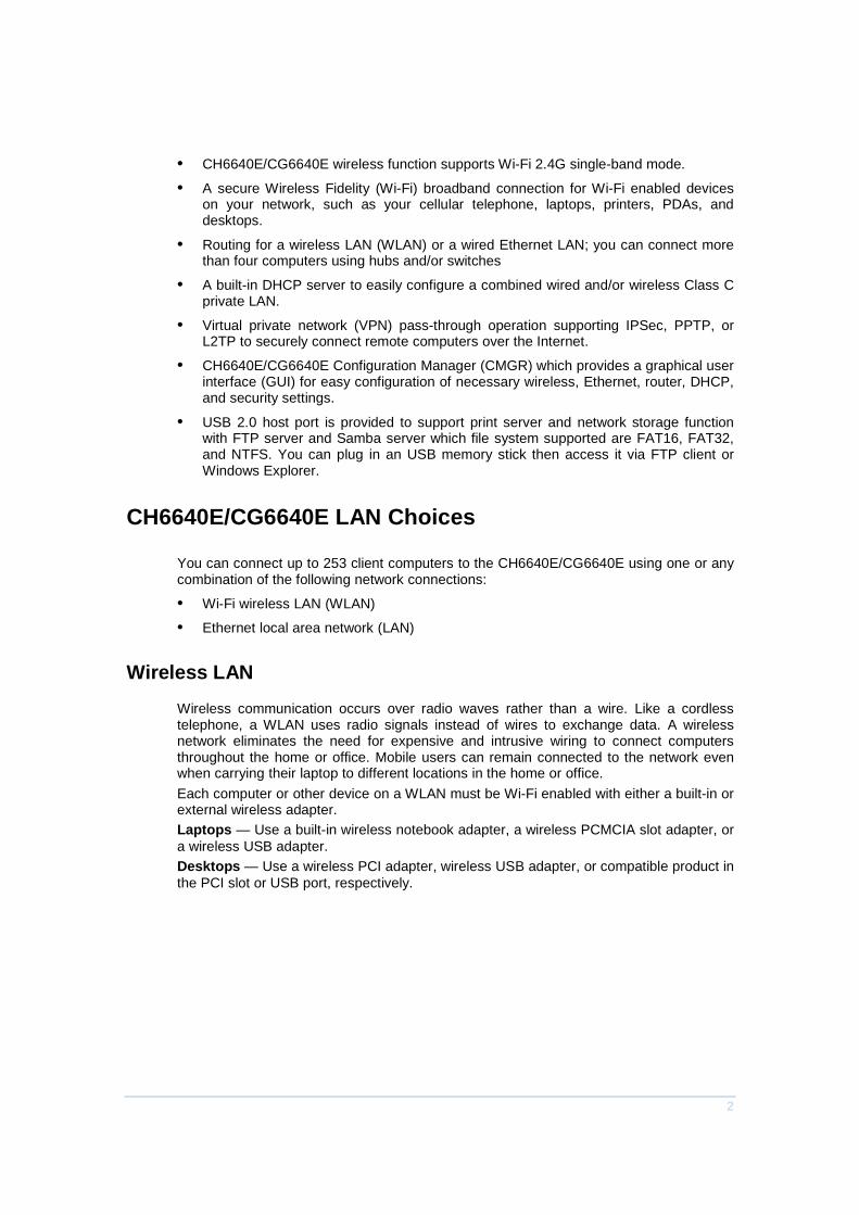
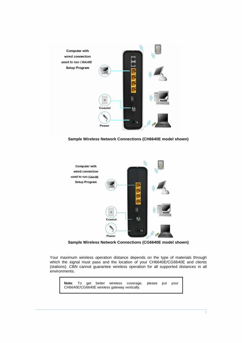
Wireless LAN
Wireless communication occurs over radio waves rather than a wire. Like a cordless telephone, a WLAN uses radio signals instead of wires to exchange data. A wireless network eliminates the need for expensive and intrusive wiring to connect computers throughout the home or office. Mobile users can remain connected to the network even when carrying their laptop to different locations in the home or office.
Each computer or other device on a WLAN must be Wi-Fi enabled with either a built-in or external wireless adapter. Laptops — Use a built-in wireless notebook adapter, a wireless PCMCIA slot adapter, or a wireless USB adapter. Desktops — Use a wireless PCI adapter, wireless USB adapter, or compatible product in the PCI slot or USB port, respectively.
3
Sample Wireless Network Connections (CH6640E model shown)
Sample Wireless Network Connections (CG6640E model shown)
Your maximum wireless operation distance depends on the type of materials through which the signal must pass and the location of your CH6640E/CG6640E and clients (stations). CBN cannot guarantee wireless operation for all supported distances in all environments.
Note: To get better wireless coverage, please put your CH6640E/CG6640E wireless gateway vertically.

4
Wired Ethernet LAN
You can easily connect any PC with an Ethernet cable to the CH6640E/CG6640E Ethernet port. Because the CH6640E/CG6640E Ethernet port supports auto-MDIX, you can use a straight-through or cross-over cable to connect a hub, switch, or computer. Use category 5, or better, cabling for all Ethernet connections.
Sample Ethernet to Computer Connection (CH6640E mod el shown)
Sample Ethernet to Computer Connection (CG6640E mod el shown)
5
A wired Ethernet LAN with more than four computers requires one or more hubs, switches, or routers. You can:
• Connect a hub or switch to any Ethernet port on the CH6640E/CG6640E.
• Use Ethernet hubs, switches, or routers to connect up to any combination of 253 computers and wireless clients to the CH6640E/CG6640E.
More detailed information on Ethernet cabling is beyond the scope of this document.
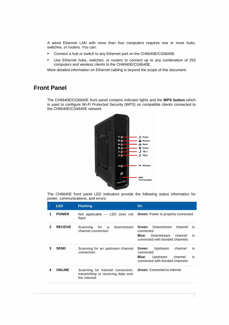
Front Panel
The CH6640E/CG6640E front panel contains indicator lights and the WPS button which is used to configure Wi-Fi Protected Security (WPS) on compatible clients connected to the CH6640E/CG6640E network.
The CH6640E front panel LED indicators provide the following status information for power, communications, and errors:
LED Flashing On
1 POWER Not applicable — LED does not flash
Green : Power is properly connected
2 RECEIVE Scanning for a downstream channel connection
Green : Downstream channel is connected Blue : Downstream channel is connected with bonded channels
3 SEND Scanning for an upstream channel connection
Green : Upstream channel is connected Blue : Upstream channel is connected with bonded channels
4 ONLINE Scanning for Internet connection; transmitting or receiving data over the Internet
Green : Connected to Internet
6
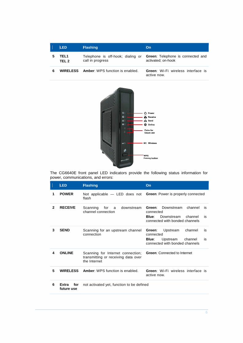
LED Flashing On
5 TEL1 TEL 2
Telephone is off-hook; dialing or call in progress
Green : Telephone is connected and activated; on-hook
6 WIRELESS Amber : WPS function is enabled. Green : Wi-Fi wireless interface is active now.
The CG6640E front panel LED indicators provide the following status information for power, communications, and errors:
LED Flashing On
1 POWER Not applicable — LED does not flash
Green : Power is properly connected
2 RECEIVE Scanning for a downstream channel connection
Green : Downstream channel is connected Blue : Downstream channel is connected with bonded channels
3 SEND Scanning for an upstream channel connection
Green : Upstream channel is connected Blue : Upstream channel is connected with bonded channels
4 ONLINE Scanning for Internet connection; transmitting or receiving data over the Internet
Green : Connected to Internet
5 WIRELESS Amber : WPS function is enabled. Green : Wi-Fi wireless interface is active now.
6 Extra for future use
not activated yet, function to be defined
7
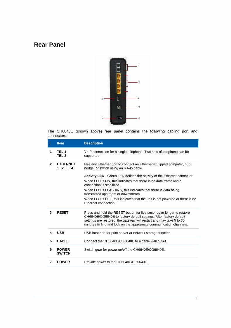
Rear Panel
The CH6640E (shown above) rear panel contains the following cabling port and connectors:
Item Description
1 TEL 1 TEL 2
VoIP connection for a single telephone. Two sets of telephone can be supported.
2 ETHERNET 1 2 3 4
Use any Ethernet port to connect an Ethernet-equipped computer, hub, bridge, or switch using an RJ-45 cable. Activity LED - Green LED defines the activity of the Ethernet connector.
When LED is ON, this indicates that there is no data traffic and a connection is stabilized.
When LED is FLASHING, this indicates that there is data being transmitted upstream or downstream.
When LED is OFF, this indicates that the unit is not powered or there is no Ethernet connection.
3 RESET Press and hold the RESET button for five seconds or longer to restore CH6640E/CG6640E to factory default settings. After factory default settings are restored, the gateway will restart and may take 5 to 30 minutes to find and lock on the appropriate communication channels.
4 USB USB host port for print server or network storage function
5 CABLE Connect the CH6640E/CG6640E to a cable wall outlet.
6 POWER SWITCH
Switch gear for power on/off the CH6640E/CG6640E.
7 POWER Provide power to the CH6640E/CG6640E.
8
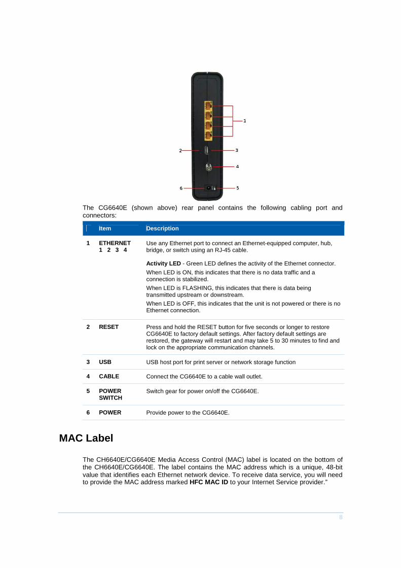
The CG6640E (shown above) rear panel contains the following cabling port and connectors:
Item Description
1 ETHERNET 1 2 3 4
Use any Ethernet port to connect an Ethernet-equipped computer, hub, bridge, or switch using an RJ-45 cable. Activity LED - Green LED defines the activity of the Ethernet connector.
When LED is ON, this indicates that there is no data traffic and a connection is stabilized.
When LED is FLASHING, this indicates that there is data being transmitted upstream or downstream.
When LED is OFF, this indicates that the unit is not powered or there is no Ethernet connection.
2 RESET Press and hold the RESET button for five seconds or longer to restore CG6640E to factory default settings. After factory default settings are restored, the gateway will restart and may take 5 to 30 minutes to find and lock on the appropriate communication channels.
3 USB USB host port for print server or network storage function
4 CABLE Connect the CG6640E to a cable wall outlet.
5 POWER SWITCH
Switch gear for power on/off the CG6640E.
6 POWER Provide power to the CG6640E.
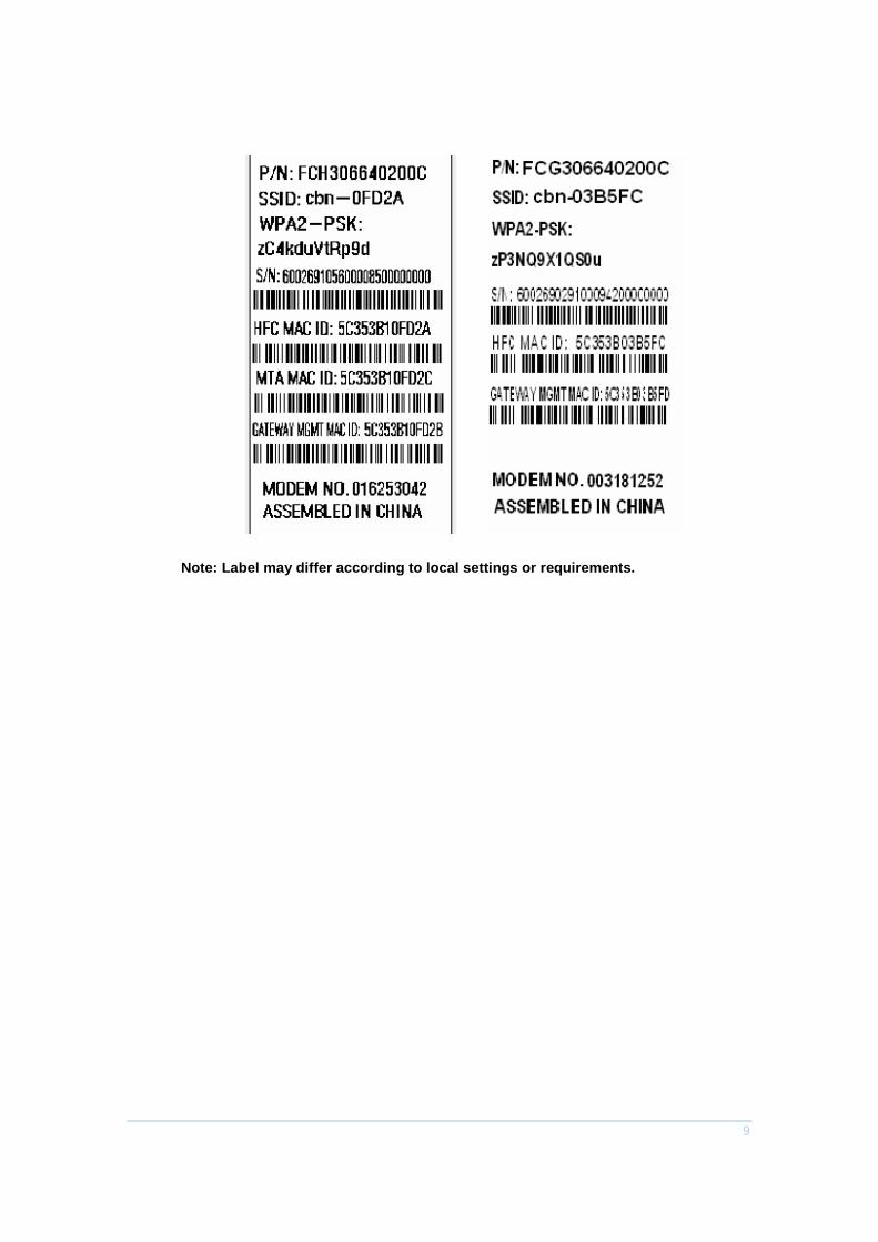
MAC Label
The CH6640E/CG6640E Media Access Control (MAC) label is located on the bottom of the CH6640E/CG6640E. The label contains the MAC address which is a unique, 48-bit value that identifies each Ethernet network device. To receive data service, you will need to provide the MAC address marked HFC MAC ID to your Internet Service provider.”
9
Note: Label may differ according to local settings or requirements.
10
2 Getting Started
Inside the Box
Before you install the CH6640E/CG6640E Wireless Gateway, verify that the following items are included in the box with the CH6640E/CG6640E:
Item Description
Power cord
Connects the CH6640E/CG6640E to an AC electrical outlet
Software License & Regulatory Card
Contains software license, warranty, and safety information for the CH6640E/CG6640E.
CH6640E/CG6640E Install Sheet
Provides basic information for setting up the CH6640E/CG6640E
You must have the latest service packs and patches installed on your computer for your operating system.
You will need a 75-ohm coaxial cable with F-type connectors to connect the CH6640E/CG6640E to the nearest cable outlet. If a TV is connected to the cable outlet, you may need a 5 to 900 MHz RF splitter and two additional coaxial cables to use the TV and the CH6640E/CG6640E.
11
Before You Begin
Take the following precautions before installing the CH6640E/CG6640E:
• Postpone installation until there is no risk of thunderstorm or lightning activity in the area.
• To avoid potential shock, always unplug the power cord from the wall outlet or other power source before disconnecting it from the CH6640E/CG6640E rear panel.
• To prevent overheating the CH6640E/CG6640E, do not block the ventilation holes on the sides of the unit. Do not open the unit. Refer all service to your Internet Service provider.
Check that you have the required cables, adapters, and adapter software. Verify that the proper drivers are installed for the Ethernet adapter on each networked computer. For information on WLAN setup, see Setting Up Your Wireless LAN.
System Requirements
Your computer must meet the following minimum requirements:
• Computer with Pentium© class or better processor
• Windows XP, Windows Vista, Macintosh, or UNIX operating system with available operating system CD-ROM
• Any web browser, such as Microsoft Internet Explorer, Netscape Navigator®, or Mozilla® Firefox®
12
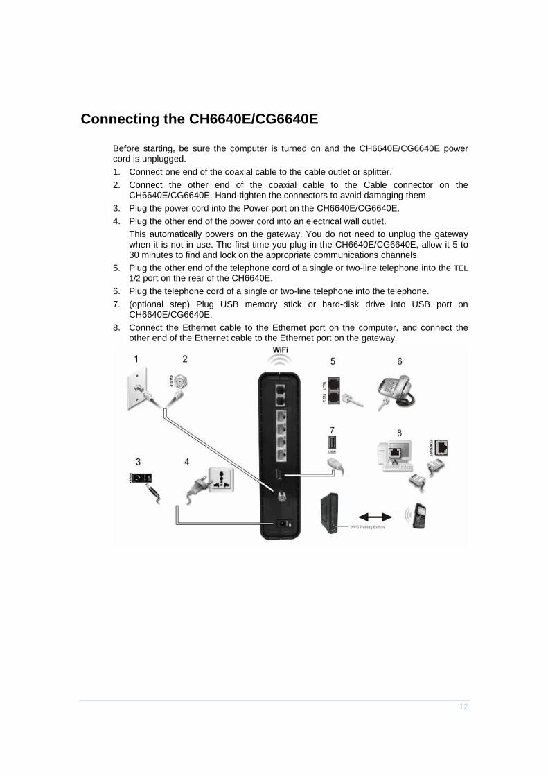
Connecting the CH6640E/CG6640E
Before starting, be sure the computer is turned on and the CH6640E/CG6640E power cord is unplugged.
1. Connect one end of the coaxial cable to the cable outlet or splitter.
2. Connect the other end of the coaxial cable to the Cable connector on the CH6640E/CG6640E. Hand-tighten the connectors to avoid damaging them.
3. Plug the power cord into the Power port on the CH6640E/CG6640E.
4. Plug the other end of the power cord into an electrical wall outlet.
This automatically powers on the gateway. You do not need to unplug the gateway when it is not in use. The first time you plug in the CH6640E/CG6640E, allow it 5 to 30 minutes to find and lock on the appropriate communications channels.
5. Plug the other end of the telephone cord of a single or two-line telephone into the TEL 1/2 port on the rear of the CH6640E.
6. Plug the telephone cord of a single or two-line telephone into the telephone.
7. (optional step) Plug USB memory stick or hard-disk drive into USB port on CH6640E/CG6640E.
8. Connect the Ethernet cable to the Ethernet port on the computer, and connect the other end of the Ethernet cable to the Ethernet port on the gateway.
13
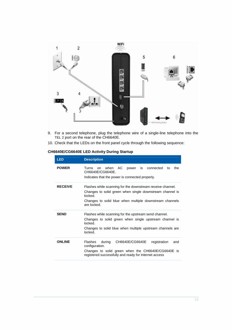
9. For a second telephone, plug the telephone wire of a single-line telephone into the
TEL 2 port on the rear of the CH6640E.
10. Check that the LEDs on the front panel cycle through the following sequence:
CH6640E/CG6640E LED Activity During Startup
LED Description
POWER Turns on when AC power is connected to the CH6640E/CG6640E.
Indicates that the power is connected properly.
RECEIVE Flashes while scanning for the downstream receive channel.
Changes to solid green when single downstream channel is locked.
Changes to solid blue when multiple downstream channels are locked.
SEND Flashes while scanning for the upstream send channel.
Changes to solid green when single upstream channel is locked.
Changes to solid blue when multiple upstream channels are locked.
ONLINE Flashes during CH6640E/CG6640E registration and configuration.
Changes to solid green when the CH6640E/CG6640E is registered successfully and ready for Internet access
14
Wall Mounting the CH6640E/CG6640E
You have the option to wall mount the CH6640E/CG6640E. Do the following before mounting the CH6640E/CG6640E on the wall:
• Locate the unit as specified by the local or national codes governing residential or business cable TV and communications services.
• Follow all local standards for installing a network interface unit/network interface device (NIU/NID).
• Make sure the AC power plug is disconnected from the wall outlet and all cables are removed from the back of the CH6640E/CG6640E before starting the installation.
• Decide if you want to mount the CH6640E/CG6640E horizontally or vertically.
If possible, mount the unit to concrete, masonry, a wooden stud, or some other very solid wall material. Use anchors if necessary (for example, if you must mount the unit on drywall).
CAUTION: Before drilling holes, check the structure for potential damage to water, gas, or electrical lines.
Do the following to mount your CH6640E/CG6640E on the wall:
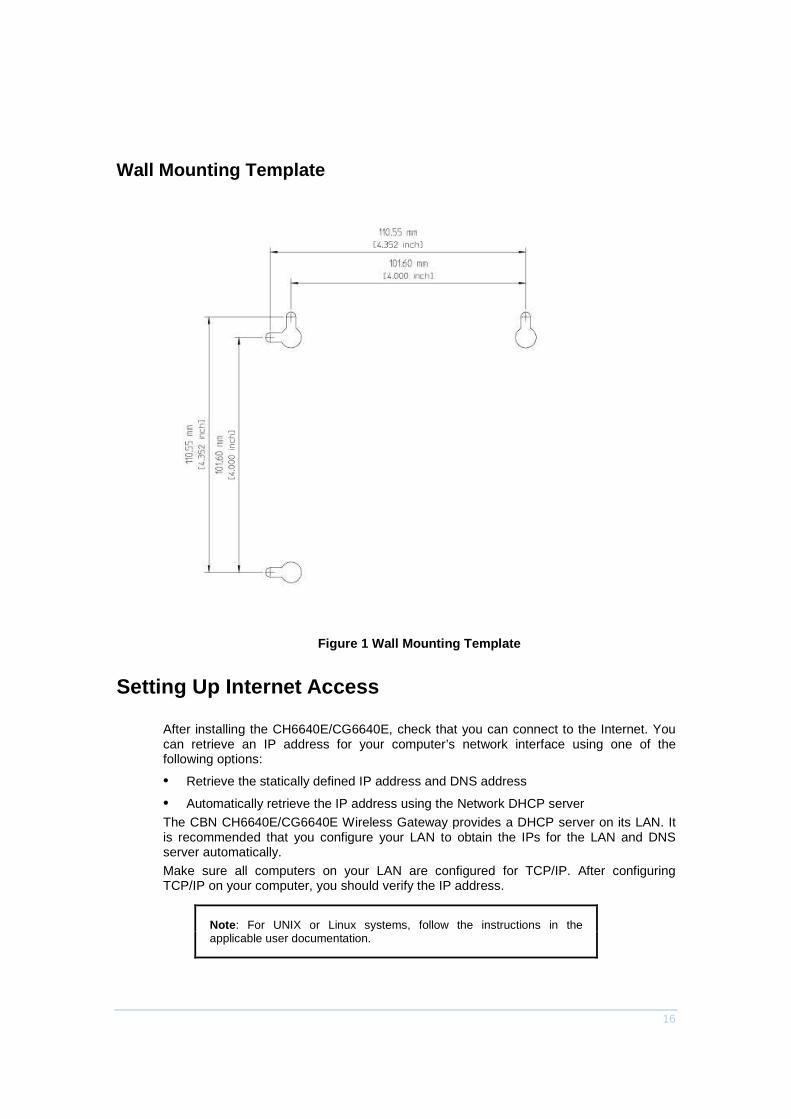
1. Print a copy of the Wall Mounting Template.
2. Measure the printed template with a ruler to ensure that it is the correct size.
3. Use a center punch to mark the center of the holes.
4. On the wall, locate the marks for the mounting holes.
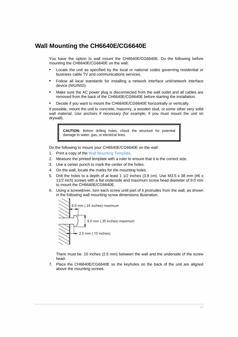
5. Drill the holes to a depth of at least 1 1/2 inches (3.8 cm). Use M3.5 x 38 mm (#6 x 11/2 inch) screws with a flat underside and maximum screw head diameter of 9.0 mm to mount the CH6640E/CG6640E.
6. Using a screwdriver, turn each screw until part of it protrudes from the wall, as shown in the following wall mounting screw dimensions illustration.
6.0 mm (.24 inches) maximum
9.0 mm (.35 inches) maximum
2.5 mm (.10 inches).
There must be .10 inches (2.5 mm) between the wall and the underside of the screw head.
7. Place the CH6640E/CG6640E so the keyholes on the back of the unit are aligned above the mounting screws.

15
8. Slide the CH6640E/CG6640E down until it stops against the top of the keyhole opening.
9. After mounting, reconnect the coaxial cable input and Ethernet connection.
10. Plug the power cord into the +12VDC connector on the gateway and the electrical outlet.
11. Route the cables to avoid any safety hazards.
16
Wall Mounting Template
Figure 1 Wall Mounting Template
Setting Up Internet Access
After installing the CH6640E/CG6640E, check that you can connect to the Internet. You can retrieve an IP address for your computer’s network interface using one of the following options:
• Retrieve the statically defined IP address and DNS address
• Automatically retrieve the IP address using the Network DHCP server
The CBN CH6640E/CG6640E Wireless Gateway provides a DHCP server on its LAN. It is recommended that you configure your LAN to obtain the IPs for the LAN and DNS server automatically.
Make sure all computers on your LAN are configured for TCP/IP. After configuring TCP/IP on your computer, you should verify the IP address.
Note: For UNIX or Linux systems, follow the instructions in the applicable user documentation.
17
Configuring TCP/IP in Windows XP
1. Open the Control Panel .
2. Double-click Network Connections to list the Dial-up and LAN or High-Speed Internet connections.
3. Right-click the network connection for your network interface. 4. Select Properties from the drop-down menu to display the Local Area Connection
Properties window. Be sure Internet Protocol (TCP/IP) is checked. 5. Select Internet Protocol (TCP/IP) and click Properties to display the Internet
Protocol (TCP/IP) Properties window. 6. Select Obtain an IP address automatically and Obtain DNS server address
automatically .
7. Click OK to save the TCP/IP settings and exit the TCP/IP Properties window.
8. Close the Local Area Connection Properties window and then exit the Control Panel.
9. When you complete the TCP/IP configuration, continue with Verifying the IP Address in Windows XP.
Configuring TCP/IP in Windows Vista
1. Open the Control Panel .
2. Click Network and Internet to display the Network and Internet window.
3. Click Network and Sharing Center to display the Network and Sharing Center window.
4. Click Manage network connections to display the LAN or High-Speed Internet connections window.
5. Right-click the network connection for the network interface you want to change. 6. Click Properties to display the Local Area Connection Properties window.
Vista may prompt you for an administrator password or confirmation. Type the password or confirmation, then click Continue .
7. Click Networking tab, then select Internet Protocol Version 4 (IPv4) .
8. Click Properties to display the Internet Protocol Version 4 (TCP/IPv4) Properties window.
9. Select Obtain an IP address automatically and Obtain DNS server address automatically .
10. Click OK to save the TCP/IP settings and close the Internet Protocol Version 4 (TCP/IPv4) Properties window.
11. Click OK to close the Local Area Connection Properties window.
12. Close the remaining windows and exit the Control Panel.
13. When you complete the TCP/IP configuration, continue with Verifying the IP Address in Windows Vista.
Verifying the IP Address in Windows XP
To check the IP address: 1. On the Windows Desktop, click Start .
2. Select Run . The Run window is displayed.
3. Type cmd and click OK.
18
4. Type ipconfig and press ENTER to display your IP configuration.
If an Auto-configuration IP Address displays, this indicates possible cable network problems or an improper connection between your computer and the CH6640E/CG6640E.
Check the following:
• Your cable connections
• Whether you can see cable-TV channels on your television After successfully verifying your cable connections and proper cable-TV operation, you can renew your IP address.
Verifying the IP Address in Windows Vista
Do the following to verify the IP address: 1. On the Windows Desktop, click Start .
2. Click All Programs .
3. Click Accessories .
4. Click Command Prompt to open a command prompt window.
5. Type ipconfig and press Enter to display the IP address.
If an Auto-configuration IP Address displays, this indicates an improper connection between your computer and the CH6640E/CG6640E, or there are possible cable network problems.
Renewing Your IP Address
To renew your IP address in Windows XP or Windows Vista: 1. Open a command prompt window.
2. At the command prompt, type ipconfig /renew and press ENTER to obtain a new IP address.
3. Type exit and press ENTER to close the command prompt window.
If after performing this procedure your computer still cannot access the Internet, call your cable service provider for assistance.
Setting Up a Wi-Fi Network
Do the following to set up a Wi-Fi network using the WPS button on the CH6640E/CG6640E:
1. Power on the CH6640E/CG6640E.
2. Power on the WPS-enabled devices you want to have access to the network, such as a PC, router, or telephone.
The Wi-Fi network will automatically detect the WPS devices. 3. Press WPS button on the CH6640E/CG6640E.
4. If applicable, press WPS button on the other WPS devices.
19
For normal operation, you do not need to change most default settings. Carefully consider the following caution statements:
Starting the CH6640E/CG6640E Configuration Manager (CMGR)
The CH6640E/CG6640E Configuration Manager (CMGR) allows you to change and view the settings on your CH6640E/CG6640E.
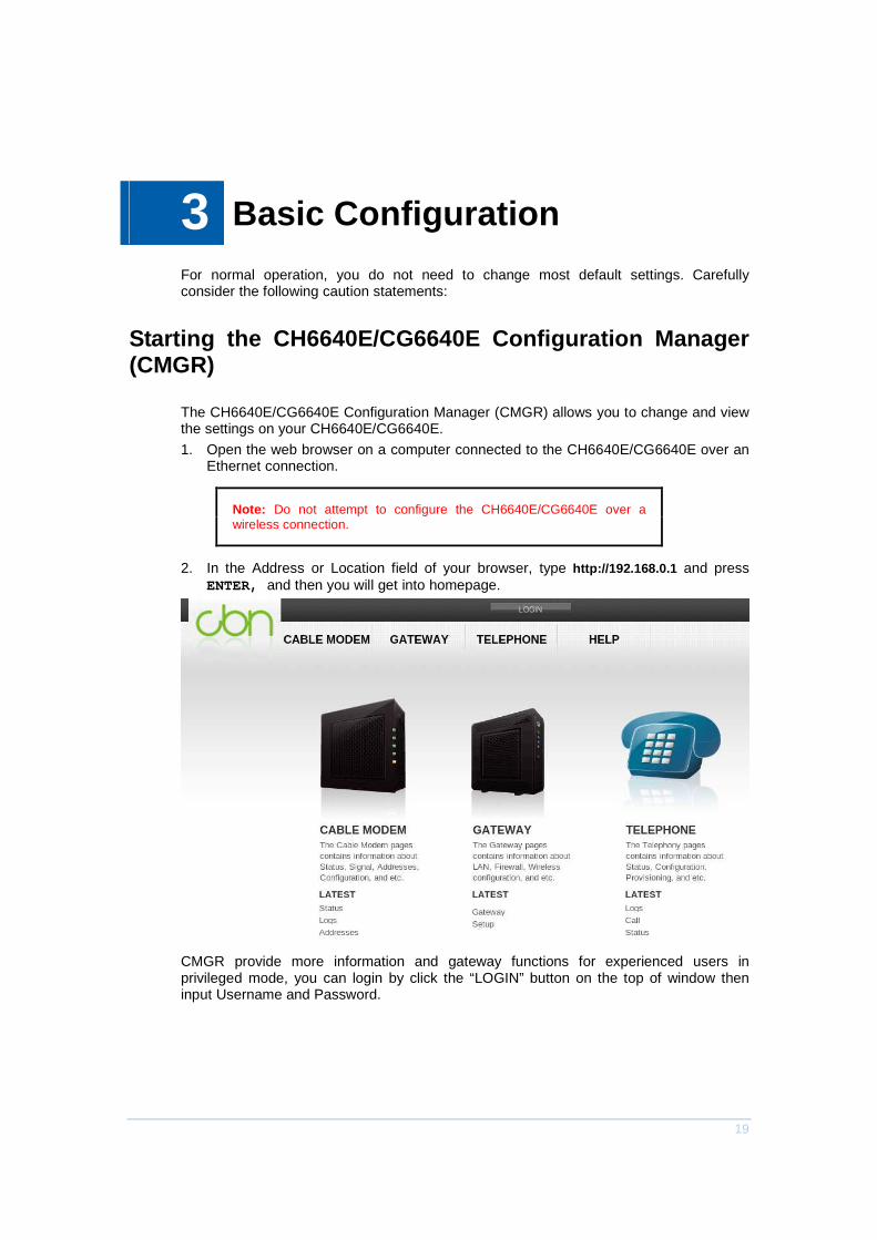
1. Open the web browser on a computer connected to the CH6640E/CG6640E over an Ethernet connection.
Note: Do not attempt to configure the CH6640E/CG6640E over a wireless connection.
2. In the Address or Location field of your browser, type http://192.168.0.1 and press ENTER, and then you will get into homepage.
CMGR provide more information and gateway functions for experienced users in privileged mode, you can login by click the “LOGIN” button on the top of window then input Username and Password.
3 Basic Configuration
20
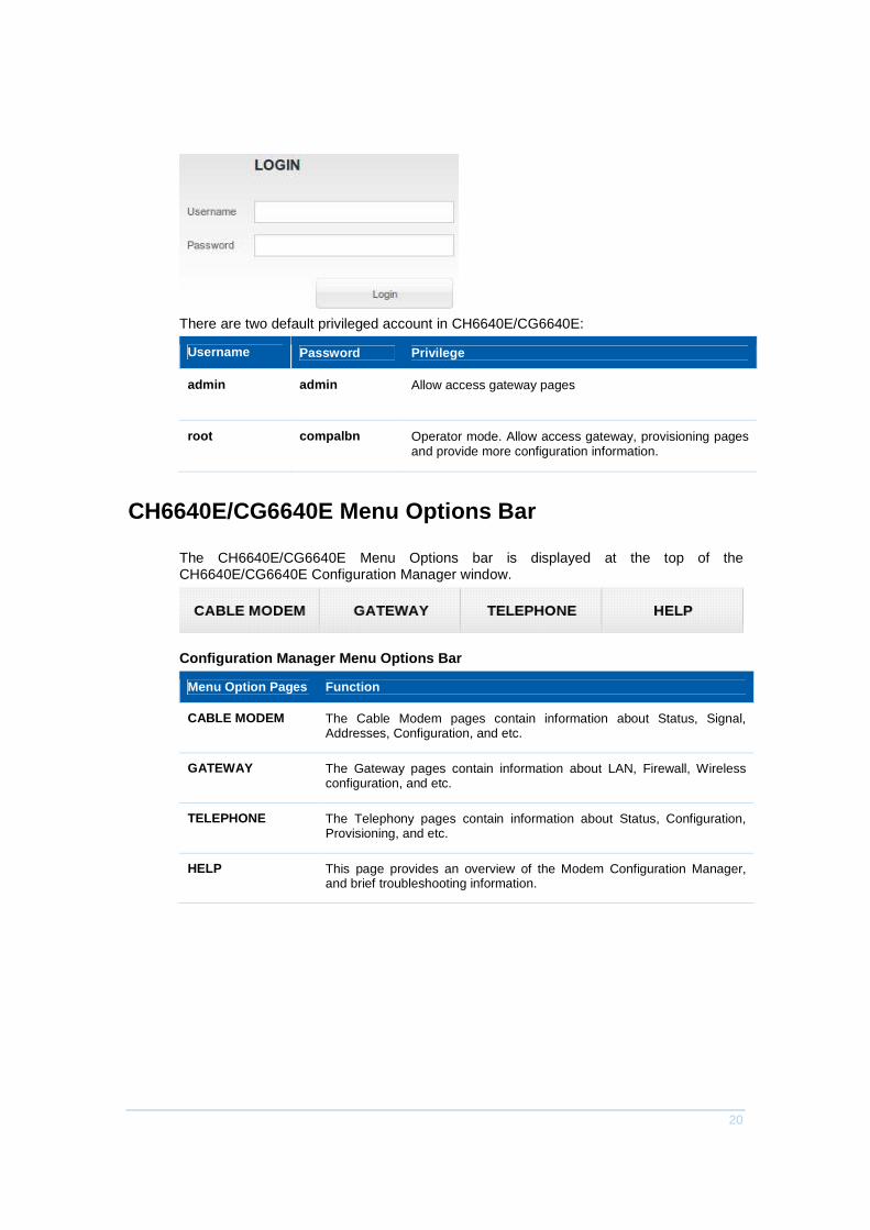
There are two default privileged account in CH6640E/CG6640E:
Username Password Privilege
admin admin Allow access gateway pages
root compalbn Operator mode. Allow access gateway, provisioning pages and provide more configuration information.
CH6640E/CG6640E Menu Options Bar
The CH6640E/CG6640E Menu Options bar is displayed at the top of the CH6640E/CG6640E Configuration Manager window.
Configuration Manager Menu Options Bar
Menu Option Pages Function
CABLE MODEM The Cable Modem pages contain information about Status, Signal, Addresses, Configuration, and etc.
GATEWAY The Gateway pages contain information about LAN, Firewall, Wireless configuration, and etc.
TELEPHONE The Telephony pages contain information about Status, Configuration, Provisioning, and etc.
HELP This page provides an overview of the Modem Configuration Manager, and brief troubleshooting information.
21
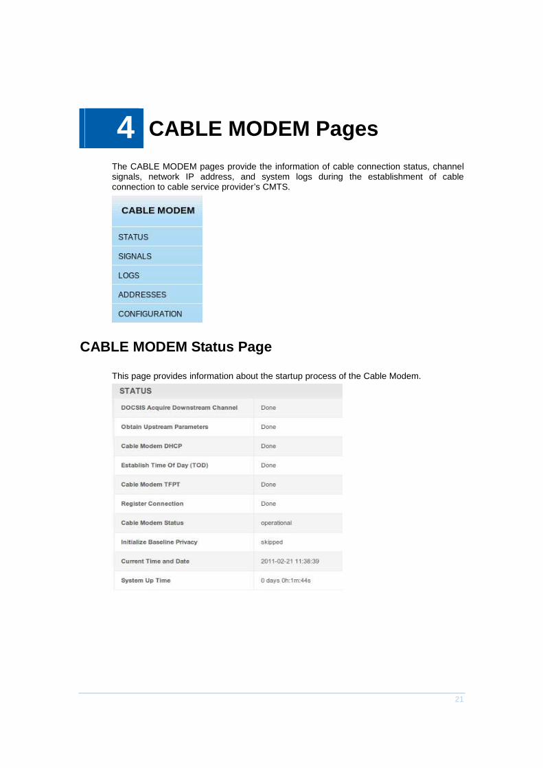
4 CABLE MODEM Pages
The CABLE MODEM pages provide the information of cable connection status, channel signals, network IP address, and system logs during the establishment of cable connection to cable service provider’s CMTS.
CABLE MODEM Status Page
This page provides information about the startup process of the Cable Modem.
22
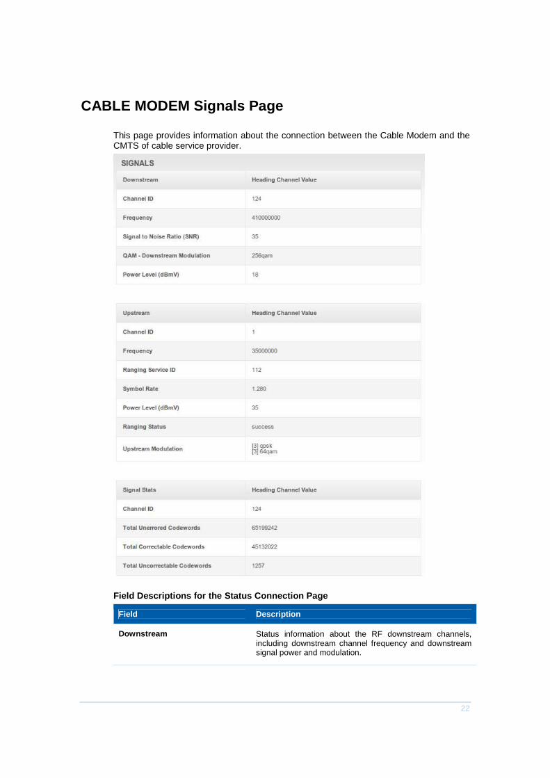
CABLE MODEM Signals Page
This page provides information about the connection between the Cable Modem and the CMTS of cable service provider.
Field Descriptions for the Status Connection Page
Field Description
Downstream Status information about the RF downstream channels, including downstream channel frequency and downstream signal power and modulation.
23
Field Description
Upstream Status information about the RF upstream channels, including upstream channel ID and upstream signal power and modulation.
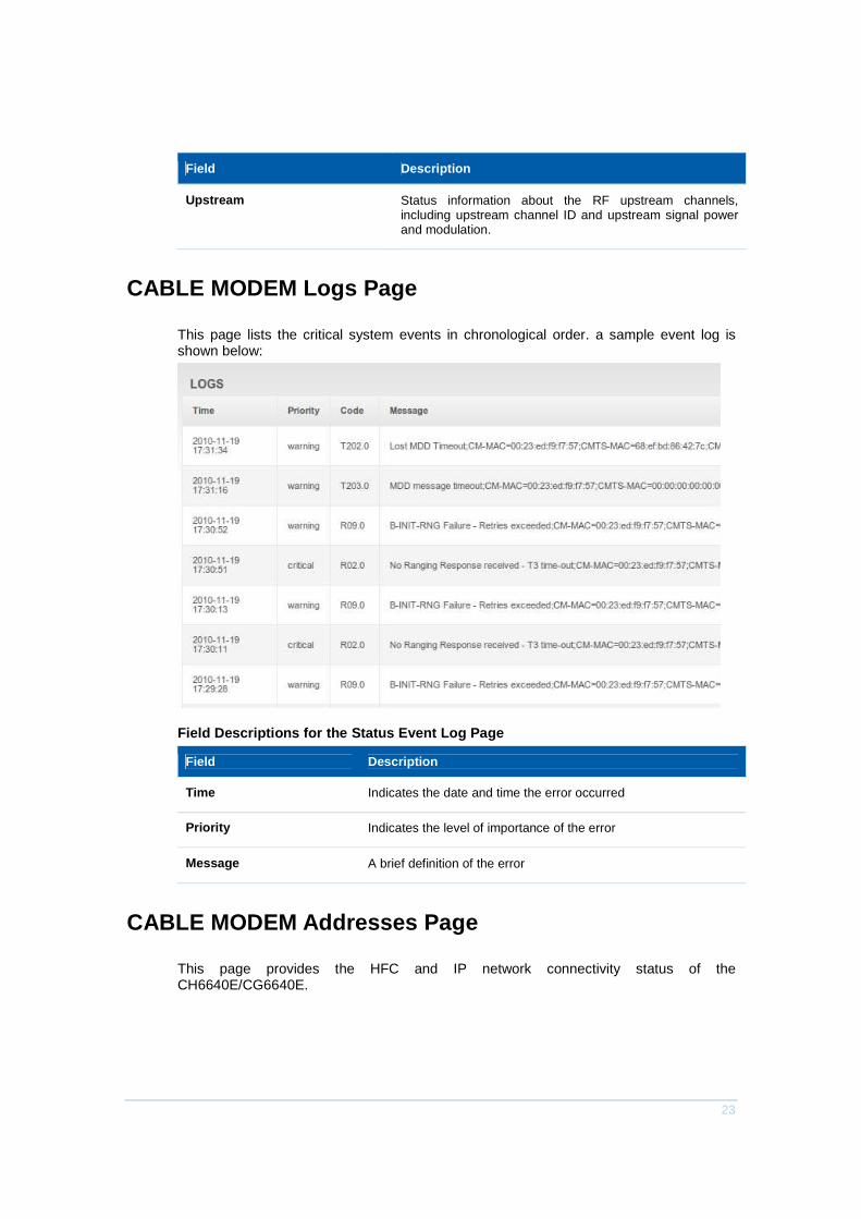
CABLE MODEM Logs Page
This page lists the critical system events in chronological order. a sample event log is shown below:
Field Descriptions for the Status Event Log Page
Field Description
Time Indicates the date and time the error occurred
Priority Indicates the level of importance of the error
Message A brief definition of the error
CABLE MODEM Addresses Page
This page provides the HFC and IP network connectivity status of the CH6640E/CG6640E.
24
CABLE MODEM Configuration Page
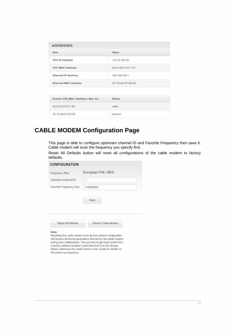
This page is able to configure upstream channel ID and Favorite Frequency then save it. Cable modem will scan the frequency you specify first.
Reset All Defaults button will reset all configurations of the cable modem to factory defaults.
25
CABLE MODEM Provisioning Page
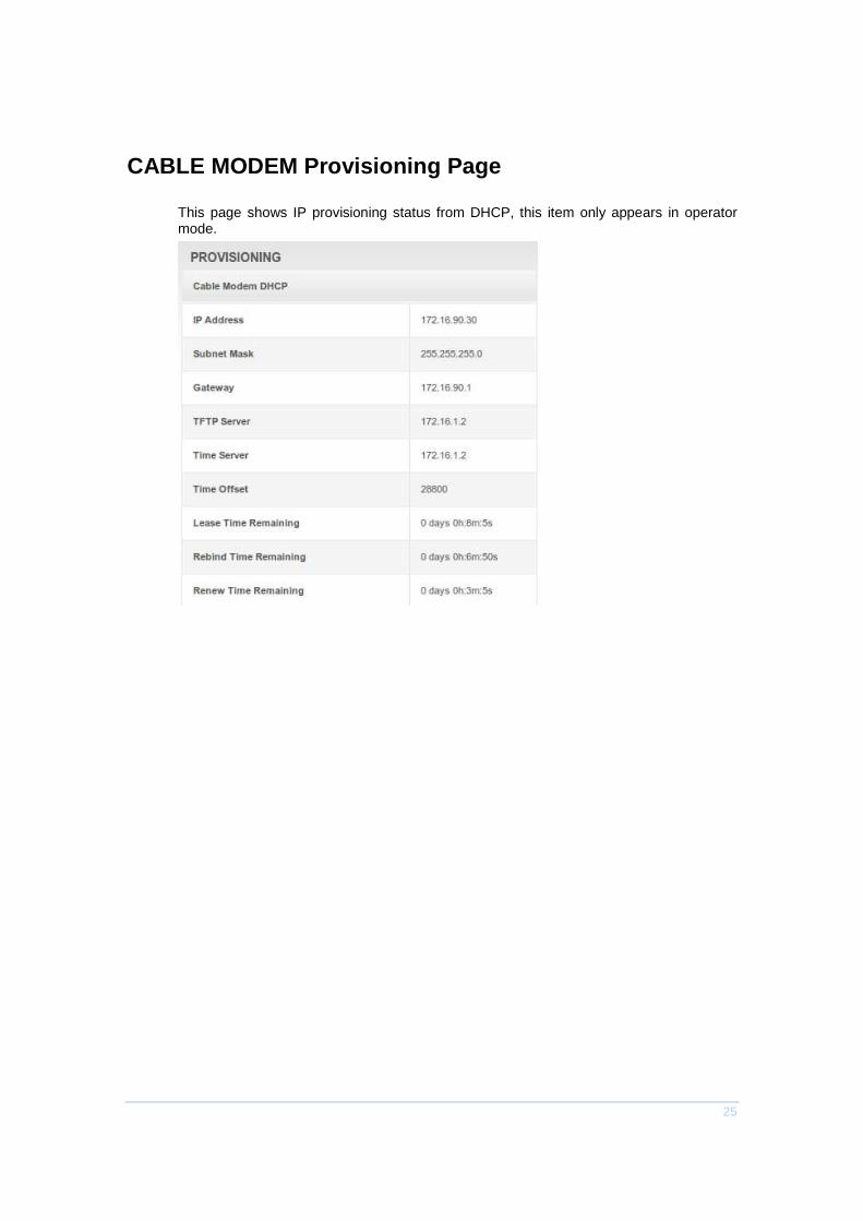
This page shows IP provisioning status from DHCP, this item only appears in operator mode.
26
5 GATEWAY Basic Pages
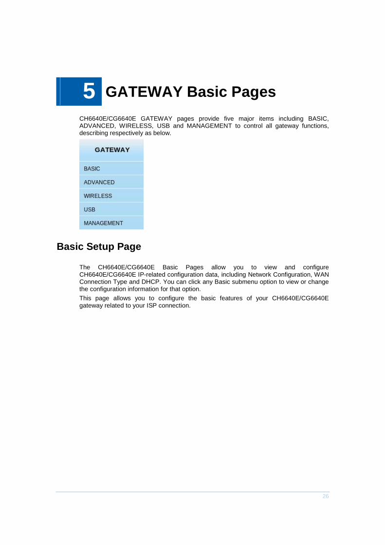
CH6640E/CG6640E GATEWAY pages provide five major items including BASIC, ADVANCED, WIRELESS, USB and MANAGEMENT to control all gateway functions, describing respectively as below.
Basic Setup Page
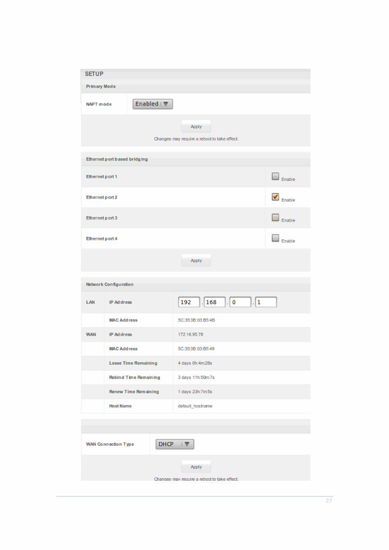
The CH6640E/CG6640E Basic Pages allow you to view and configure CH6640E/CG6640E IP-related configuration data, including Network Configuration, WAN Connection Type and DHCP. You can click any Basic submenu option to view or change the configuration information for that option.
This page allows you to configure the basic features of your CH6640E/CG6640E gateway related to your ISP connection.
27
28
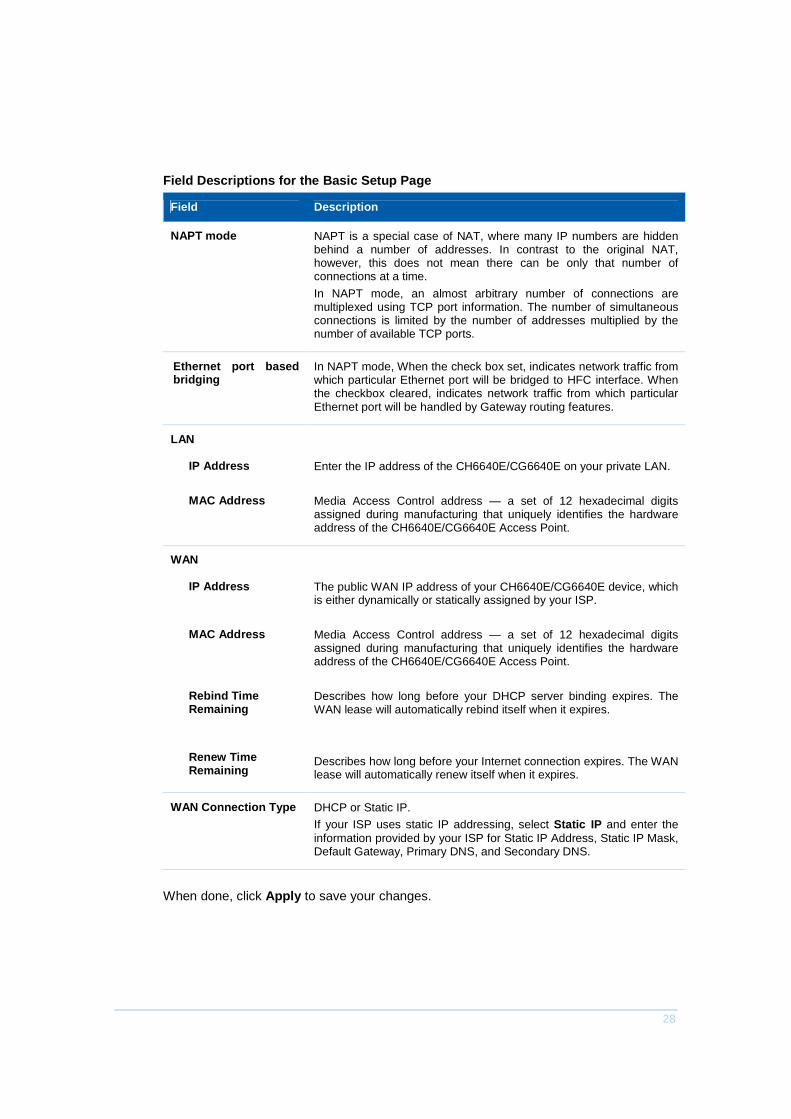
Field Descriptions for the Basic Setup Page
Field Description
NAPT mode NAPT is a special case of NAT, where many IP numbers are hidden behind a number of addresses. In contrast to the original NAT, however, this does not mean there can be only that number of connections at a time.
In NAPT mode, an almost arbitrary number of connections are multiplexed using TCP port information. The number of simultaneous connections is limited by the number of addresses multiplied by the number of available TCP ports.
Ethernet port based bridging
In NAPT mode, When the check box set, indicates network traffic from which particular Ethernet port will be bridged to HFC interface. When the checkbox cleared, indicates network traffic from which particular Ethernet port will be handled by Gateway routing features.
LAN
IP Address
MAC Address
Enter the IP address of the CH6640E/CG6640E on your private LAN.
Media Access Control address — a set of 12 hexadecimal digits assigned during manufacturing that uniquely identifies the hardware address of the CH6640E/CG6640E Access Point.
WAN
IP Address
MAC Address
Rebind Time Remaining
Renew Time Remaining
The public WAN IP address of your CH6640E/CG6640E device, which is either dynamically or statically assigned by your ISP.
Media Access Control address — a set of 12 hexadecimal digits assigned during manufacturing that uniquely identifies the hardware address of the CH6640E/CG6640E Access Point.
Describes how long before your DHCP server binding expires. The WAN lease will automatically rebind itself when it expires.
Describes how long before your Internet connection expires. The WAN lease will automatically renew itself when it expires.
WAN Connection Type DHCP or Static IP.
If your ISP uses static IP addressing, select Static IP and enter the information provided by your ISP for Static IP Address, Static IP Mask, Default Gateway, Primary DNS, and Secondary DNS.
When done, click Apply to save your changes.
29
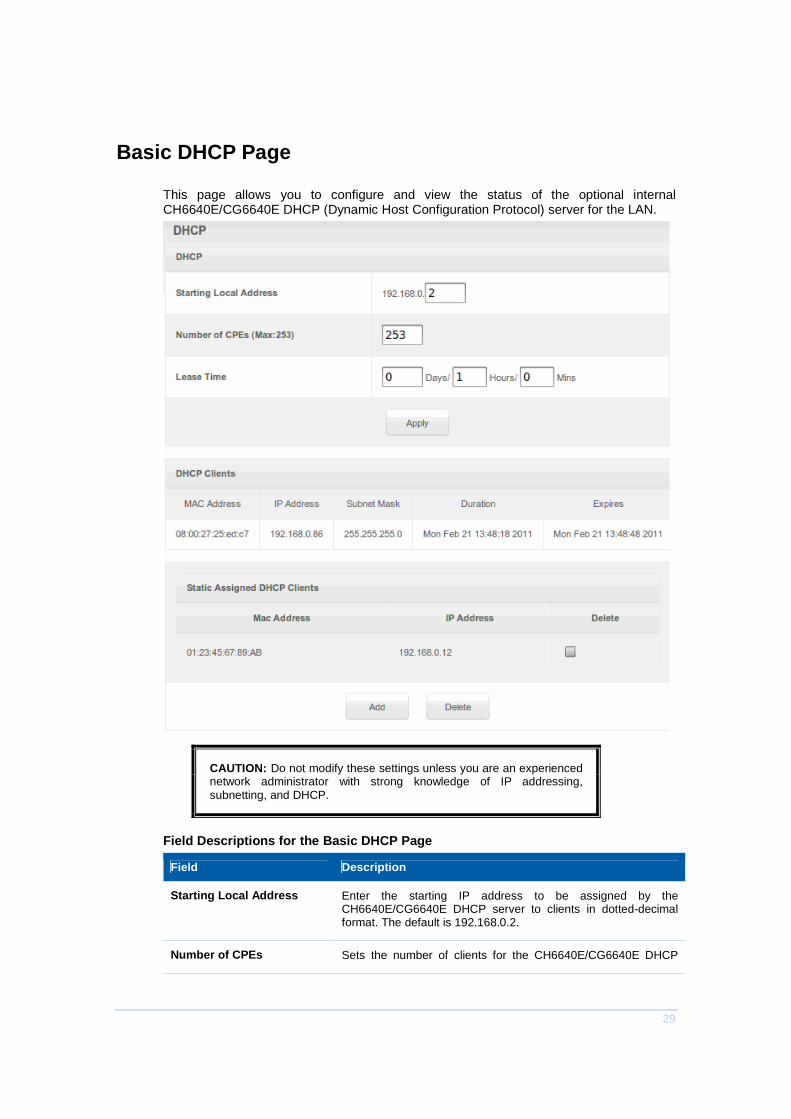
Basic DHCP Page
This page allows you to configure and view the status of the optional internal CH6640E/CG6640E DHCP (Dynamic Host Configuration Protocol) server for the LAN.
CAUTION: Do not modify these settings unless you are an experienced network administrator with strong knowledge of IP addressing, subnetting, and DHCP.
Field Descriptions for the Basic DHCP Page
Field Description
Starting Local Address Enter the starting IP address to be assigned by the CH6640E/CG6640E DHCP server to clients in dotted-decimal format. The default is 192.168.0.2.
Number of CPEs Sets the number of clients for the CH6640E/CG6640E DHCP
30
Field Description
server to assign a private IP address. There are 253 possible client addresses.
Lease Time Sets the time in seconds that the CH6640E/CG6640E DHCP server leases an IP address to a client. The default is 3600 seconds (60 minutes).
DHCP Clients Lists DHCP client device information.
Static Assigned DHCP clients
Reserve IP addresses assigned by the CH6640E/CG6640E DHCP server for specific LAN clients
When done, click Apply to save your changes.
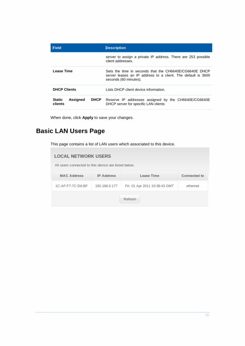
Basic LAN Users Page
This page contains a list of LAN users which associated to this device.
31
6 GATEWAY Advanced Pages
The CH6640E/CG6640E Advanced Pages allow you to configure the advanced features of the CH6640E/CG6640E:
• IP Filtering
• MAC Filtering
• Port Filtering
• Port Forwarding
• Port Triggers
• DMZ Host
• Dynamic DNS
• IDS
You can click any Advanced submenu option to view or change the advanced configuration information for that option.
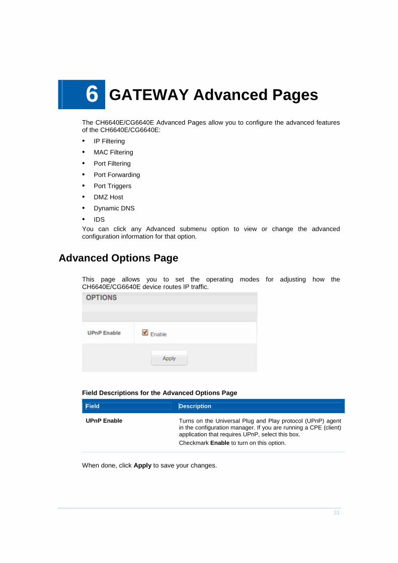
Advanced Options Page
This page allows you to set the operating modes for adjusting how the CH6640E/CG6640E device routes IP traffic.
Field Descriptions for the Advanced Options Page
Field Description
UPnP Enable Turns on the Universal Plug and Play protocol (UPnP) agent in the configuration manager. If you are running a CPE (client) application that requires UPnP, select this box.
Checkmark Enable to turn on this option.
When done, click Apply to save your changes.
32
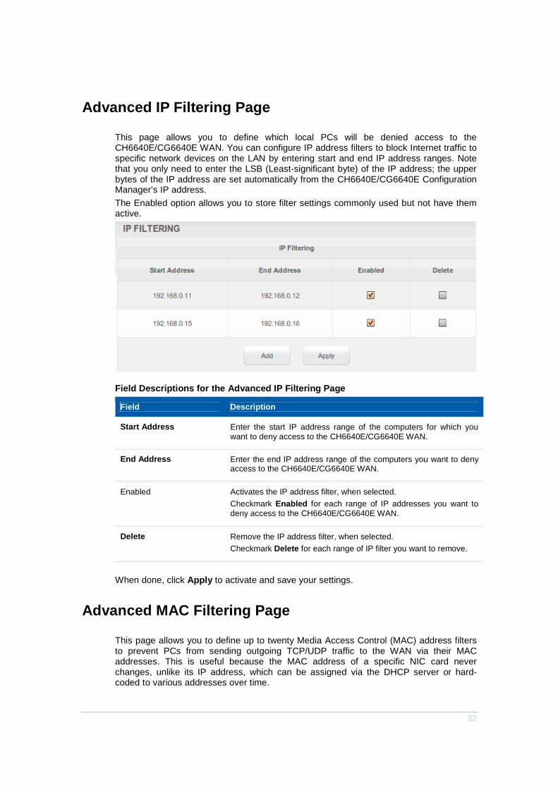
Advanced IP Filtering Page
This page allows you to define which local PCs will be denied access to the CH6640E/CG6640E WAN. You can configure IP address filters to block Internet traffic to specific network devices on the LAN by entering start and end IP address ranges. Note that you only need to enter the LSB (Least-significant byte) of the IP address; the upper bytes of the IP address are set automatically from the CH6640E/CG6640E Configuration Manager’s IP address.
The Enabled option allows you to store filter settings commonly used but not have them active.
Field Descriptions for the Advanced IP Filtering Pa ge
Field Description
Start Address Enter the start IP address range of the computers for which you want to deny access to the CH6640E/CG6640E WAN.
End Address Enter the end IP address range of the computers you want to deny access to the CH6640E/CG6640E WAN.
Enabled Activates the IP address filter, when selected.
Checkmark Enabled for each range of IP addresses you want to deny access to the CH6640E/CG6640E WAN.
Delete Remove the IP address filter, when selected.
Checkmark Delete for each range of IP filter you want to remove.
When done, click Apply to activate and save your settings.
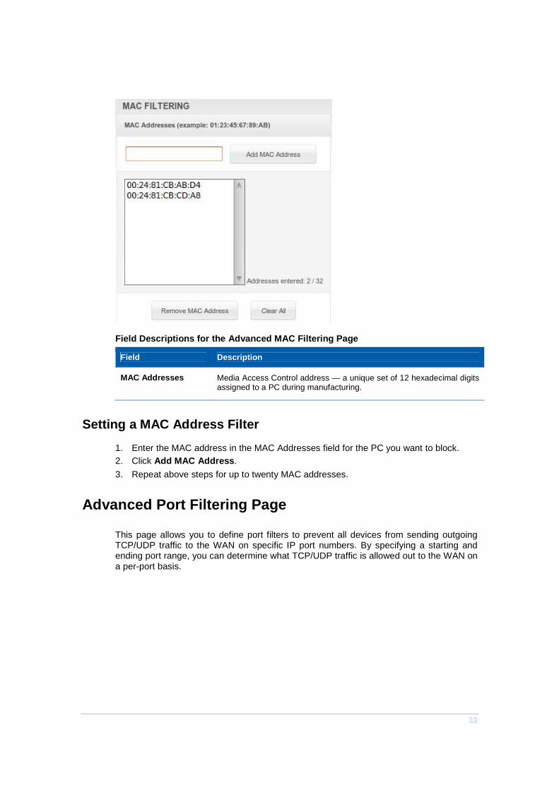
Advanced MAC Filtering Page
This page allows you to define up to twenty Media Access Control (MAC) address filters to prevent PCs from sending outgoing TCP/UDP traffic to the WAN via their MAC addresses. This is useful because the MAC address of a specific NIC card never changes, unlike its IP address, which can be assigned via the DHCP server or hard-coded to various addresses over time.
33
Field Descriptions for the Advanced MAC Filtering P age
Field Description
MAC Addresses Media Access Control address — a unique set of 12 hexadecimal digits assigned to a PC during manufacturing.
Setting a MAC Address Filter
1. Enter the MAC address in the MAC Addresses field for the PC you want to block. 2. Click Add MAC Address .
3. Repeat above steps for up to twenty MAC addresses.
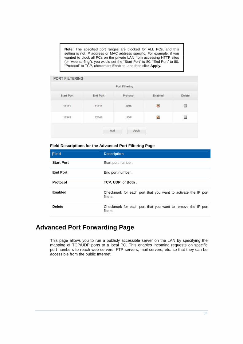
Advanced Port Filtering Page
This page allows you to define port filters to prevent all devices from sending outgoing TCP/UDP traffic to the WAN on specific IP port numbers. By specifying a starting and ending port range, you can determine what TCP/UDP traffic is allowed out to the WAN on a per-port basis.
34
Note: The specified port ranges are blocked for ALL PCs, and this setting is not IP address or MAC address specific. For example, if you wanted to block all PCs on the private LAN from accessing HTTP sites (or “web surfing”), you would set the “Start Port” to 80, “End Port” to 80, “Protocol” to TCP, checkmark Enabled, and then click Apply.
Field Descriptions for the Advanced Port Filtering Page
Field Description
Start Port Start port number.
End Port End port number.
Protocol TCP , UDP, or Both .
Enabled Checkmark for each port that you want to activate the IP port filters.
Delete Checkmark for each port that you want to remove the IP port filters.
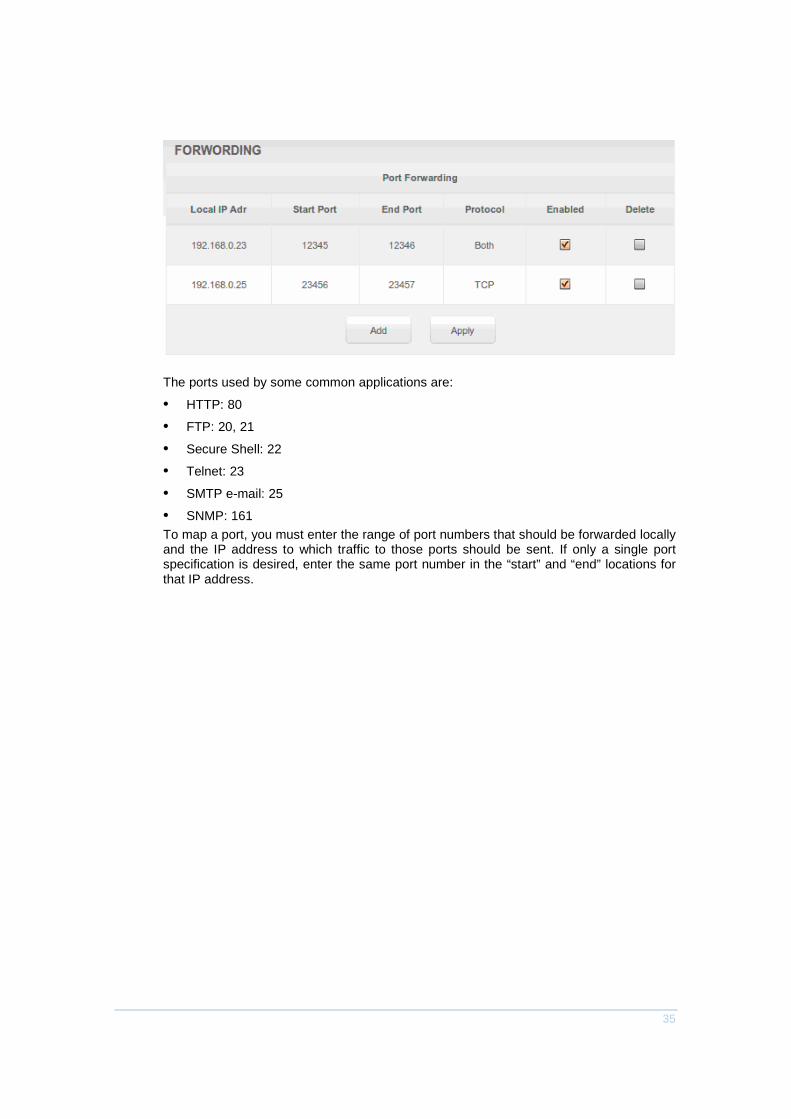
Advanced Port Forwarding Page
This page allows you to run a publicly accessible server on the LAN by specifying the mapping of TCP/UDP ports to a local PC. This enables incoming requests on specific port numbers to reach web servers, FTP servers, mail servers, etc. so that they can be accessible from the public Internet.
35
The ports used by some common applications are:
• HTTP: 80
• FTP: 20, 21
• Secure Shell: 22
• Telnet: 23
• SMTP e-mail: 25
• SNMP: 161
To map a port, you must enter the range of port numbers that should be forwarded locally and the IP address to which traffic to those ports should be sent. If only a single port specification is desired, enter the same port number in the “start” and “end” locations for that IP address.
36
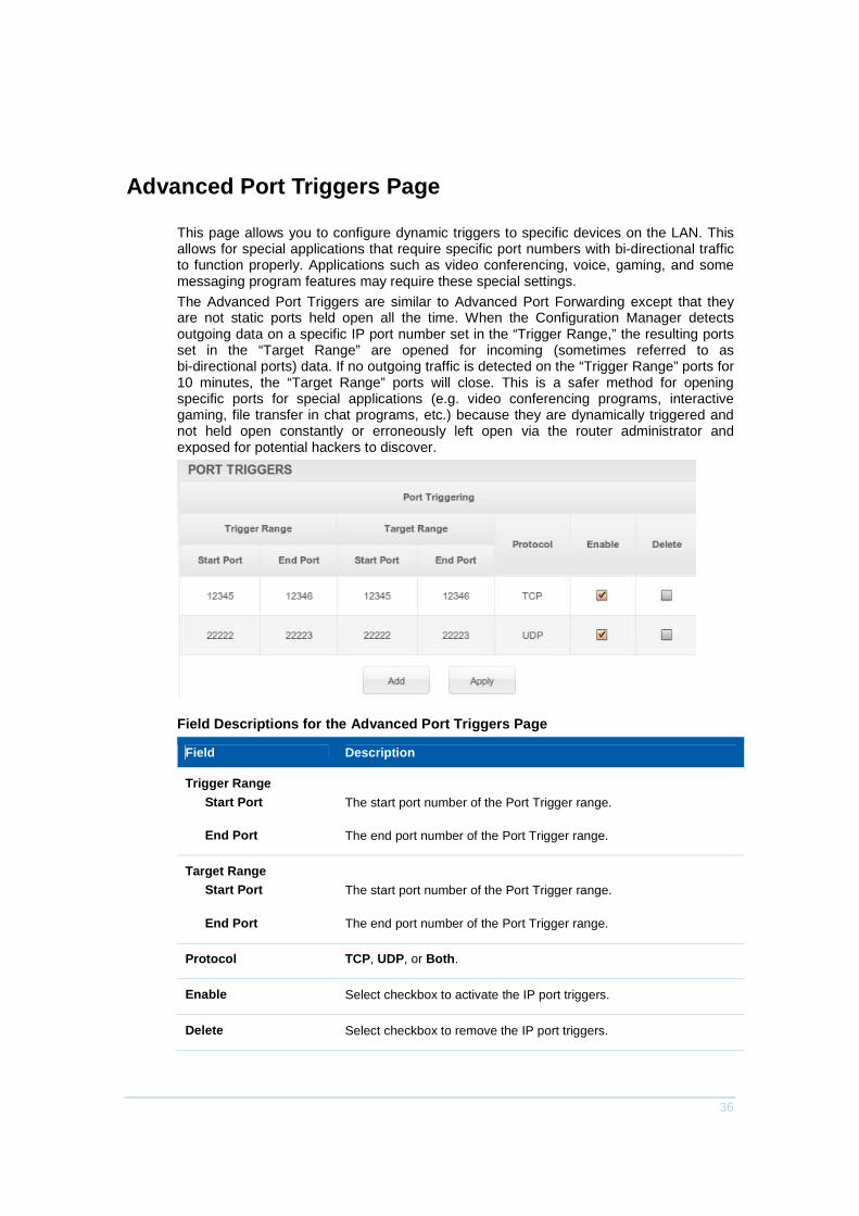
Advanced Port Triggers Page
This page allows you to configure dynamic triggers to specific devices on the LAN. This allows for special applications that require specific port numbers with bi-directional traffic to function properly. Applications such as video conferencing, voice, gaming, and some messaging program features may require these special settings.
The Advanced Port Triggers are similar to Advanced Port Forwarding except that they are not static ports held open all the time. When the Configuration Manager detects outgoing data on a specific IP port number set in the “Trigger Range,” the resulting ports set in the “Target Range” are opened for incoming (sometimes referred to as bi-directional ports) data. If no outgoing traffic is detected on the “Trigger Range” ports for 10 minutes, the “Target Range” ports will close. This is a safer method for opening specific ports for special applications (e.g. video conferencing programs, interactive gaming, file transfer in chat programs, etc.) because they are dynamically triggered and not held open constantly or erroneously left open via the router administrator and exposed for potential hackers to discover.
Field Descriptions for the Advanced Port Triggers P age
Field Description
Trigger Range
Start Port End Port
The start port number of the Port Trigger range.
The end port number of the Port Trigger range.
Target Range Start Port End Port
The start port number of the Port Trigger range.
The end port number of the Port Trigger range.
Protocol TCP , UDP, or Both .
Enable Select checkbox to activate the IP port triggers.
Delete Select checkbox to remove the IP port triggers.
37
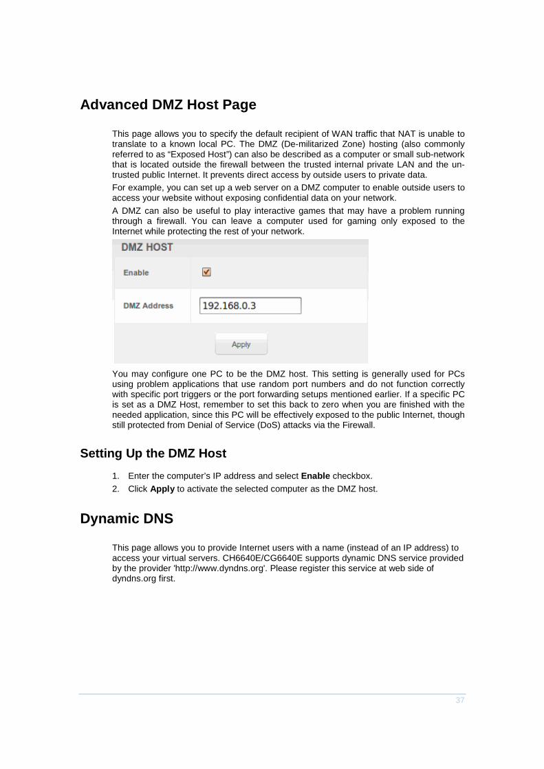
Advanced DMZ Host Page
This page allows you to specify the default recipient of WAN traffic that NAT is unable to translate to a known local PC. The DMZ (De-militarized Zone) hosting (also commonly referred to as “Exposed Host”) can also be described as a computer or small sub-network that is located outside the firewall between the trusted internal private LAN and the un-trusted public Internet. It prevents direct access by outside users to private data. For example, you can set up a web server on a DMZ computer to enable outside users to access your website without exposing confidential data on your network.
A DMZ can also be useful to play interactive games that may have a problem running through a firewall. You can leave a computer used for gaming only exposed to the Internet while protecting the rest of your network.
You may configure one PC to be the DMZ host. This setting is generally used for PCs using problem applications that use random port numbers and do not function correctly with specific port triggers or the port forwarding setups mentioned earlier. If a specific PC is set as a DMZ Host, remember to set this back to zero when you are finished with the needed application, since this PC will be effectively exposed to the public Internet, though still protected from Denial of Service (DoS) attacks via the Firewall.
Setting Up the DMZ Host
1. Enter the computer’s IP address and select Enable checkbox.
2. Click Apply to activate the selected computer as the DMZ host.
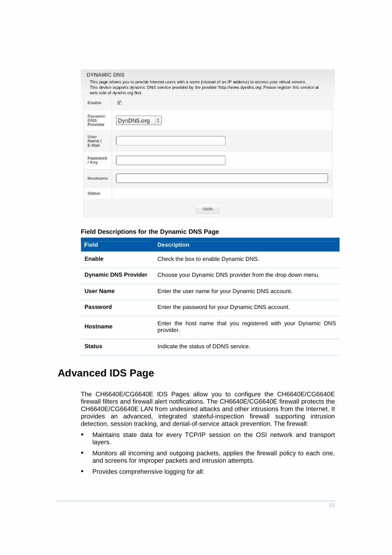
Dynamic DNS
This page allows you to provide Internet users with a name (instead of an IP address) to access your virtual servers. CH6640E/CG6640E supports dynamic DNS service provided by the provider 'http://www.dyndns.org'. Please register this service at web side of dyndns.org first.
38
Field Descriptions for the Dynamic DNS Page
Field Description
Enable Check the box to enable Dynamic DNS.
Dynamic DNS Provider Choose your Dynamic DNS provider from the drop down menu.
User Name Enter the user name for your Dynamic DNS account.
Password Enter the password for your Dynamic DNS account.
Hostname Enter the host name that you registered with your Dynamic DNS provider.
Status Indicate the status of DDNS service.
Advanced IDS Page
The CH6640E/CG6640E IDS Pages allow you to configure the CH6640E/CG6640E firewall filters and firewall alert notifications. The CH6640E/CG6640E firewall protects the CH6640E/CG6640E LAN from undesired attacks and other intrusions from the Internet. It provides an advanced, integrated stateful-inspection firewall supporting intrusion detection, session tracking, and denial-of-service attack prevention. The firewall:
• Maintains state data for every TCP/IP session on the OSI network and transport layers.
• Monitors all incoming and outgoing packets, applies the firewall policy to each one, and screens for improper packets and intrusion attempts.
• Provides comprehensive logging for all:
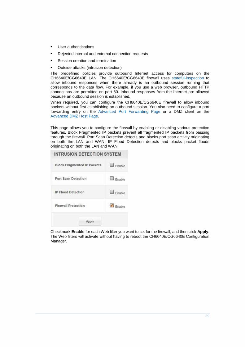
39
• User authentications
• Rejected internal and external connection requests
• Session creation and termination
• Outside attacks (intrusion detection)
The predefined policies provide outbound Internet access for computers on the CH6640E/CG6640E LAN. The CH6640E/CG6640E firewall uses stateful-inspection to allow inbound responses when there already is an outbound session running that corresponds to the data flow. For example, if you use a web browser, outbound HTTP connections are permitted on port 80. Inbound responses from the Internet are allowed because an outbound session is established.
When required, you can configure the CH6640E/CG6640E firewall to allow inbound packets without first establishing an outbound session. You also need to configure a port forwarding entry on the Advanced Port Forwarding Page or a DMZ client on the Advanced DMZ Host Page.
This page allows you to configure the firewall by enabling or disabling various protection features. Block Fragmented IP packets prevent all fragmented IP packets from passing through the firewall. Port Scan Detection detects and blocks port scan activity originating on both the LAN and WAN. IP Flood Detection detects and blocks packet floods originating on both the LAN and WAN.
Checkmark Enable for each Web filter you want to set for the firewall, and then click Apply . The Web filters will activate without having to reboot the CH6640E/CG6640E Configuration Manager.
40
7 GATEWAY Wireless Pages
The CH6640E/CG6640E Wireless Pages allow you to configure your wireless LAN (WLAN).
You can click any Wireless submenu option to view or change the configuration information for that option. WPA or WPA2 encryption provides higher security than WEP encryption, but older wireless client cards may not support the newer WPA or WPA2 encryption methods.
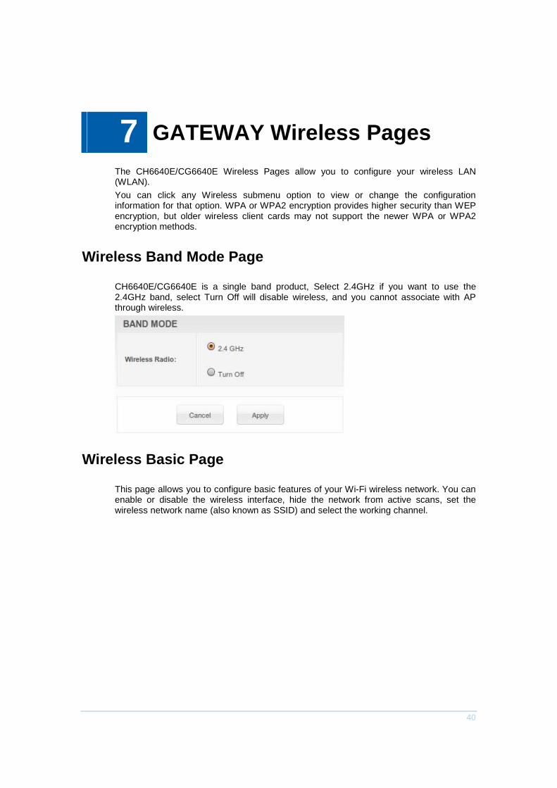
Wireless Band Mode Page
CH6640E/CG6640E is a single band product, Select 2.4GHz if you want to use the 2.4GHz band, select Turn Off will disable wireless, and you cannot associate with AP through wireless.
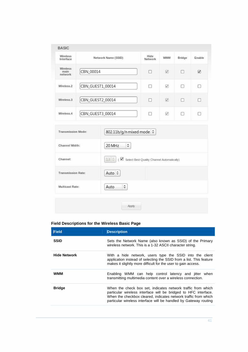
Wireless Basic Page
This page allows you to configure basic features of your Wi-Fi wireless network. You can enable or disable the wireless interface, hide the network from active scans, set the wireless network name (also known as SSID) and select the working channel.
41
Field Descriptions for the Wireless Basic Page
Field Description
SSID Sets the Network Name (also known as SSID) of the Primary wireless network. This is a 1-32 ASCII character string.
Hide Network With a hide network, users type the SSID into the client application instead of selecting the SSID from a list. This feature makes it slightly more difficult for the user to gain access.
WMM Enabling WMM can help control latency and jitter when transmitting multimedia content over a wireless connection.
Bridge When the check box set, indicates network traffic from which particular wireless interface will be bridged to HFC interface. When the checkbox cleared, indicates network traffic from which particular wireless interface will be handled by Gateway routing
42
Field Description
features.
Enable Enable or disable this wireless interface.
Transmission Mode Select which 802.11 mode is used by CH6640E/CG6640E, including 802.11b/g/n mixed mode, 802.11n only, 802.11b/g mixed mode.
Channel Width Select the channel width (20 MHz or 20/40 MHz) to be used by CH6640E/CG6640E. When 20/40MHz is selected 802.11n clients experience improved throughput using 40 MHz, while legacy clients(either 802.11a or 802.11b/g) can still be serviced without interruption using 20MHz.
Primary Channel Select primary (control) channel is in the lower or upper 20 MHz band of the bonded 40 MHz channel.
Channel Select the current channel number or control channel, you can select “Select Best Quality Channel Automatically” check box to auto select one, this value depend on Transmission Mode.
Transmission Rate Select 802.11 physical transmission rate, this value depends on Transmission Mode.
Multicast Rate Select the physical layer transmission rate used for Multicast traffic on the wireless interface, this value depend on Transmission Mode.
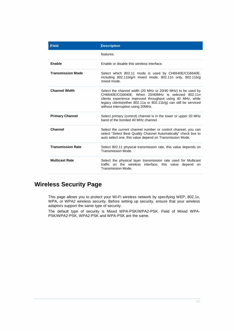
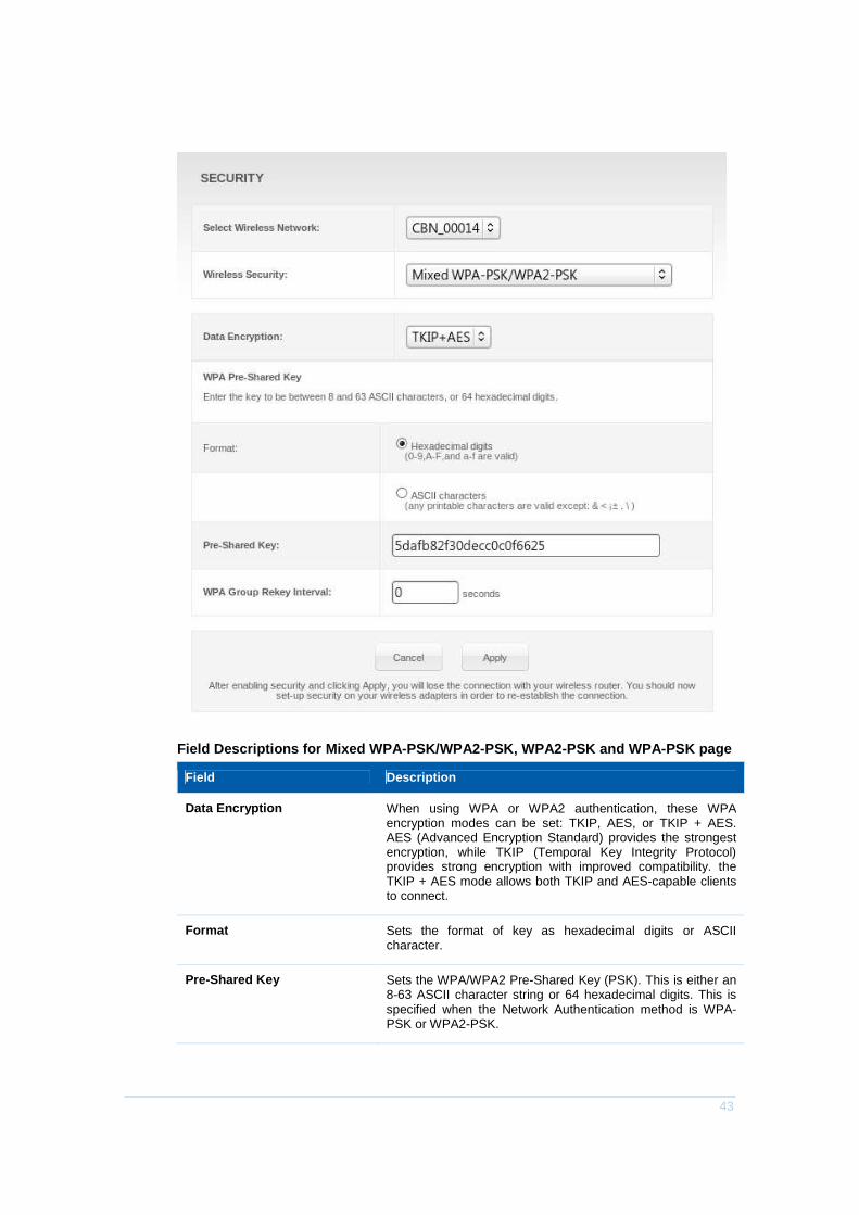
Wireless Security Page
This page allows you to protect your Wi-Fi wireless network by specifying WEP, 802.1x, WPA, or WPA2 wireless security. Before setting up security, ensure that your wireless adaptors support the same type of security.
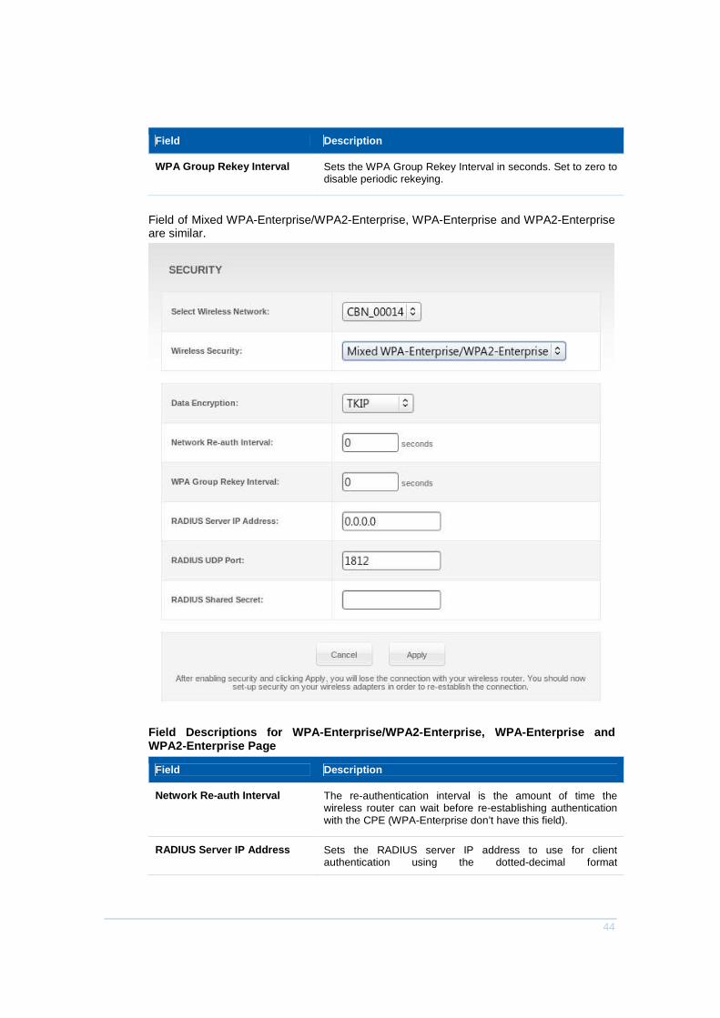
The default type of security is Mixed WPA-PSK/WPA2-PSK. Field of Mixed WPA-PSK/WPA2-PSK, WPA2-PSK and WPA-PSK are the same.
43
Field Descriptions for Mixed WPA-PSK/WPA2-PSK, WPA2 -PSK and WPA-PSK page
Field Description
Data Encryption When using WPA or WPA2 authentication, these WPA encryption modes can be set: TKIP, AES, or TKIP + AES. AES (Advanced Encryption Standard) provides the strongest encryption, while TKIP (Temporal Key Integrity Protocol) provides strong encryption with improved compatibility. the TKIP + AES mode allows both TKIP and AES-capable clients to connect.
Format Sets the format of key as hexadecimal digits or ASCII character.
Pre-Shared Key Sets the WPA/WPA2 Pre-Shared Key (PSK). This is either an 8-63 ASCII character string or 64 hexadecimal digits. This is specified when the Network Authentication method is WPA-PSK or WPA2-PSK.
44
Field Description
WPA Group Rekey Interval Sets the WPA Group Rekey Interval in seconds. Set to zero to disable periodic rekeying.
Field of Mixed WPA-Enterprise/WPA2-Enterprise, WPA-Enterprise and WPA2-Enterprise are similar.
Field Descriptions for WPA-Enterprise/WPA2-Enterpri se, WPA-Enterprise and WPA2-Enterprise Page
Field Description
Network Re-auth Interval The re-authentication interval is the amount of time the wireless router can wait before re-establishing authentication with the CPE (WPA-Enterprise don’t have this field).
RADIUS Server IP Address Sets the RADIUS server IP address to use for client authentication using the dotted-decimal format
45
Field Description
(xxx.xxx.xxx.xxx).
RADIUS UDP Port Sets the UDP port number of the RADIUS server. The default is 1812.
RADIUS Shared Secret Sets the shared secret for the RADIUS connection. The key is a 0 to 255 character ASCII string.
WEP encryption:
46
Field Descriptions for the WEP Page
Field Description
Encryption Mode Select the use of Shared Key authentication in WEP protocol. If select Open System , Shared Key authentication is optional. If select Shared Key, the Shared Key authentication is required for WEP.
Authentication Type The CPE uses either the 64-bit or 128-bit key to encrypt the challenge text and sends the encrypted text to the access point. The access point will decrypt the encrypted text and then compare the decrypted message with the original challenge text. If they are the same, the access point will let the CPE connect; if it doesn’t match, then the access point does not let the CPE connect.
Key 1 – 4 Sets the static WEP keys when WEP encryption is enabled.
• Enter 5 ASCII characters for a 64-bit key. • Enter 13 ASCII characters for a 128-bit key.
Default Transmission Key Selects the transmission key when WEP encryption is enabled.
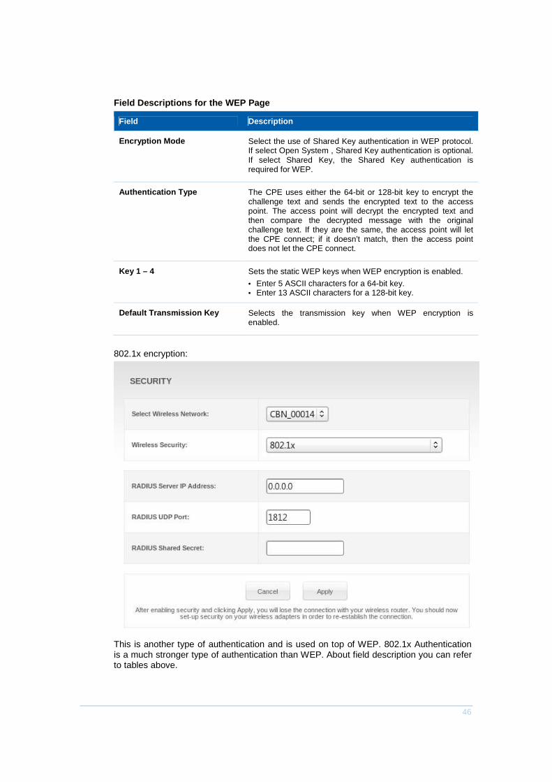
802.1x encryption:
This is another type of authentication and is used on top of WEP. 802.1x Authentication is a much stronger type of authentication than WEP. About field description you can refer to tables above.
47
Wireless WPS Page
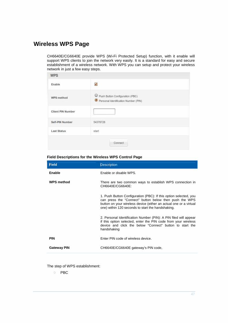
CH6640E/CG6640E provide WPS (Wi-Fi Protected Setup) function, with it enable will support WPS clients to join the network very easily. It is a standard for easy and secure establishment of a wireless network. With WPS you can setup and protect your wireless network in just a few easy steps.
Field Descriptions for the Wireless WPS Control Pag e
Field Description
Enable Enable or disable WPS.
WPS method There are two common ways to establish WPS connection in CH6640E/CG6640E:
1. Push Button Configuration (PBC): If this option selected, you can press the “Connect” button below then push the WPS button on your wireless device (either an actual one or a virtual one) within 120 seconds to start the handshaking.
2. Personal Identification Number (PIN): A PIN filed will appear if this option selected, enter the PIN code from your wireless device and click the below “Connect” button to start the handshaking
PIN Enter PIN code of wireless device.
Gateway PIN CH6640E/CG6640E gateway’s PIN code,
The step of WPS establishment:
PBC
48
1. Click or press the WPS button on the CH6640E/CG6640E’s front panel or select Push Button Configuration (PBC) option radio then click “Connect” button in the web page “Home / Gateway / Wireless / WPS”, the wireless LED will flash with orange color.
2. Click or press the WPS button on the wireless device within 120 seconds.
3. If WPS connection successfully established, the wireless LED will turn green.
PIN
1. In web page “Home / Gateway / Wireless / WPS”, select Personal Identification Number (PIN) option radio then a “PIN” column will appear.
2. Enter the wireless device’s PIN code that is normally printed on the device's sticker or generated by connection manager of that device.
3. Click “Connect”, then the wireless LED will flash with orange color.
4. Start PIN registration process by connection manager of that device within 120 seconds.
5. If WPS connection successfully established, the wireless LED will turn green.
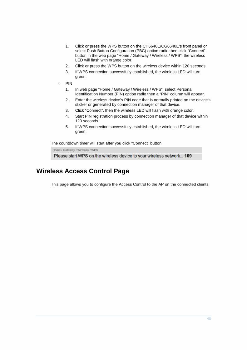
The countdown timer will start after you click “Connect” button
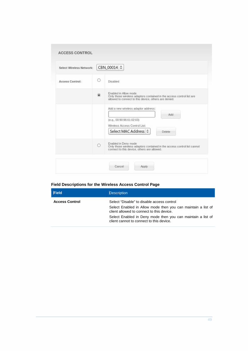
Wireless Access Control Page
This page allows you to configure the Access Control to the AP on the connected clients.
49
Field Descriptions for the Wireless Access Control Page
Field Description
Access Control Select “Disable” to disable access control
Select Enabled in Allow mode then you can maintain a list of client allowed to connect to this device.
Select Enabled in Deny mode then you can maintain a list of client cannot to connect to this device.
50
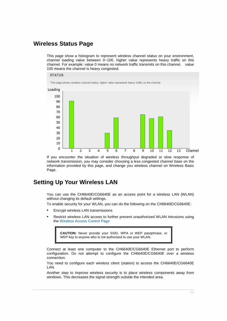
Wireless Status Page
This page show a histogram to represent wireless channel status on your environment, channel loading value between 0~100, higher value represents heavy traffic on this channel. For example: value 0 means no network traffic transmits on this channel, value 100 means the channel is heavy congested.
If you encounter the situation of wireless throughput degraded or slow response of network transmission, you may consider choosing a less congested channel base on the information provided by this page, and change you wireless channel on Wireless Basic Page.
Setting Up Your Wireless LAN
You can use the CH6640E/CG6640E as an access point for a wireless LAN (WLAN) without changing its default settings.
To enable security for your WLAN, you can do the following on the CH6640E/CG6640E:
• Encrypt wireless LAN transmissions
• Restrict wireless LAN access to further prevent unauthorized WLAN intrusions using the Wireless Access Control Page
CAUTION: Never provide your SSID, WPA or WEP passphrase, or WEP key to anyone who is not authorized to use your WLAN.
Connect at least one computer to the CH6640E/CG6640E Ethernet port to perform configuration. Do not attempt to configure the CH6640E/CG6640E over a wireless connection.
You need to configure each wireless client (station) to access the CH6640E/CG6640E LAN.
Another step to improve wireless security is to place wireless components away from windows. This decreases the signal strength outside the intended area.
51
Encrypting Wireless LAN Transmissions
To prevent unauthorized viewing of data transmitted over your WLAN, you must encrypt your wireless transmissions. Choose one of the following:
Encrypting Wireless LAN Transmissions
Configure on the CH6640E/CG6640E Required on Each Wireless Client
if all of your wireless clients support Wi-Fi Protected Access (WPA), recommending configuring WPA on the CH6640E/CG6640E
If you use a local pre-shared key (WPA-PSK) passphrase, you must configure the identical passphrase on the CH6640E/CG6640E and on each wireless client. Home and small-office settings typically use a local passphrase.
Otherwise, configure WEP on the CH6640E/CG6640E
You must configure the identical WEP key on the CH6640E/CG6640E and on each wireless client.
If all of your wireless clients support WPA encryption, recommending using WPA instead of WEP because WPA:
• Provides much stronger encryption and is more secure
• Provides authentication to ensure that only authorized users can log in to your WLAN
• Is much easier to configure
• Uses a standard algorithm on all compliant products to generate a key from a textual passphrase
• Will be incorporated into the new IEEE 802.11i wireless networking standard
For new wireless LANs, recommending purchasing client adapters that support WPA encryption.
52
8 GATEWAY USB Pages (optional)
The CH6640E/CG6640E support a variety of USB devices including printer and storage. You can plug USB printers and storages on the device and share them through internet.
Print Server
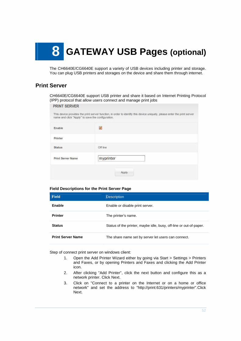
CH6640E/CG6640E support USB printer and share it based on Internet Printing Protocol (IPP) protocol that allow users connect and manage print jobs
Field Descriptions for the Print Server Page
Field Description
Enable Enable or disable print server.
Printer The printer’s name.
Status Status of the printer, maybe idle, busy, off-line or out-of-paper.
Print Server Name The share name set by server let users can connect.
Step of connect print server on windows client:
1. Open the Add Printer Wizard either by going via Start > Settings > Printers and Faxes, or by opening Printers and Faxes and clicking the Add Printer icon.
2. After clicking "Add Printer", click the next button and configure this as a network printer. Click Next.
3. Click on "Connect to a printer on the Internet or on a home or office network" and set the address to "http://print:631/printers/myprinter".Click Next.
53
4. The wizard will prompt you to select a driver for your printer.
5. If all went well, you should see complete window. Click Finish.
FTP Server
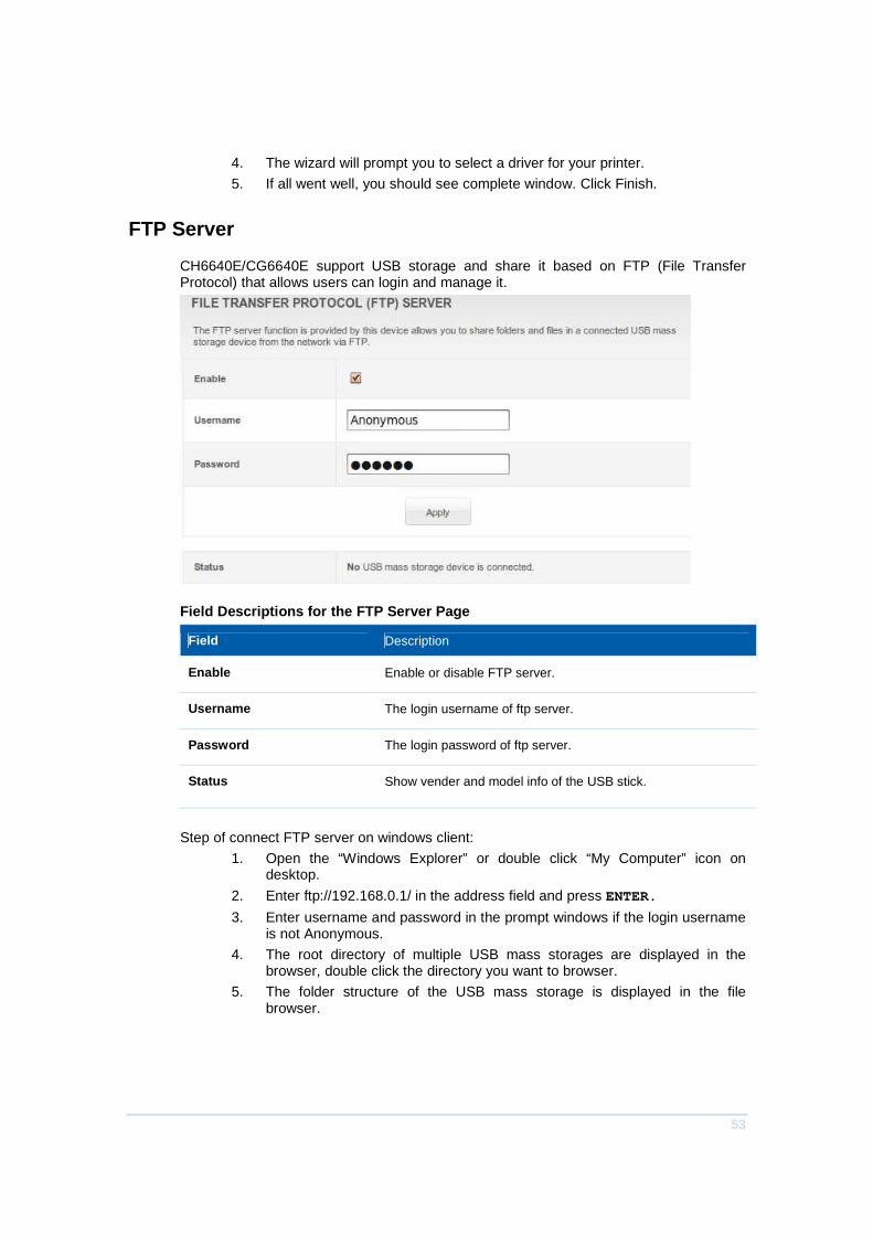
CH6640E/CG6640E support USB storage and share it based on FTP (File Transfer Protocol) that allows users can login and manage it.
Field Descriptions for the FTP Server Page
Field Description
Enable Enable or disable FTP server.
Username The login username of ftp server.
Password The login password of ftp server.
Status Show vender and model info of the USB stick.
Step of connect FTP server on windows client:
1. Open the “Windows Explorer” or double click “My Computer” icon on desktop.
2. Enter ftp://192.168.0.1/ in the address field and press ENTER.
3. Enter username and password in the prompt windows if the login username is not Anonymous.
4. The root directory of multiple USB mass storages are displayed in the browser, double click the directory you want to browser.
5. The folder structure of the USB mass storage is displayed in the file browser.
54
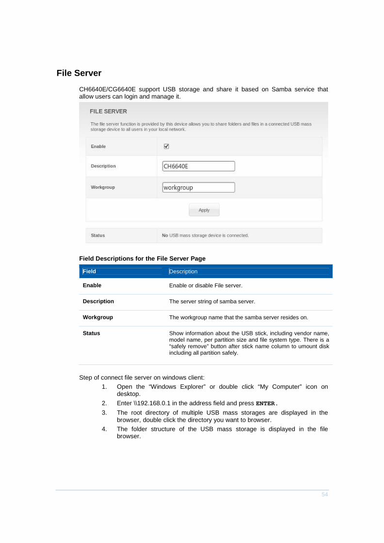
File Server
CH6640E/CG6640E support USB storage and share it based on Samba service that allow users can login and manage it.
Field Descriptions for the File Server Page
Field Description
Enable Enable or disable File server.
Description The server string of samba server.
Workgroup The workgroup name that the samba server resides on.
Status Show information about the USB stick, including vendor name, model name, per partition size and file system type. There is a “safely remove” button after stick name column to umount disk including all partition safely.
Step of connect file server on windows client:
1. Open the “Windows Explorer” or double click “My Computer” icon on desktop.
2. Enter \\192.168.0.1 in the address field and press ENTER.
3. The root directory of multiple USB mass storages are displayed in the browser, double click the directory you want to browser.
4. The folder structure of the USB mass storage is displayed in the file browser.
55
9 GATEWAY MANAGEMENT Pages
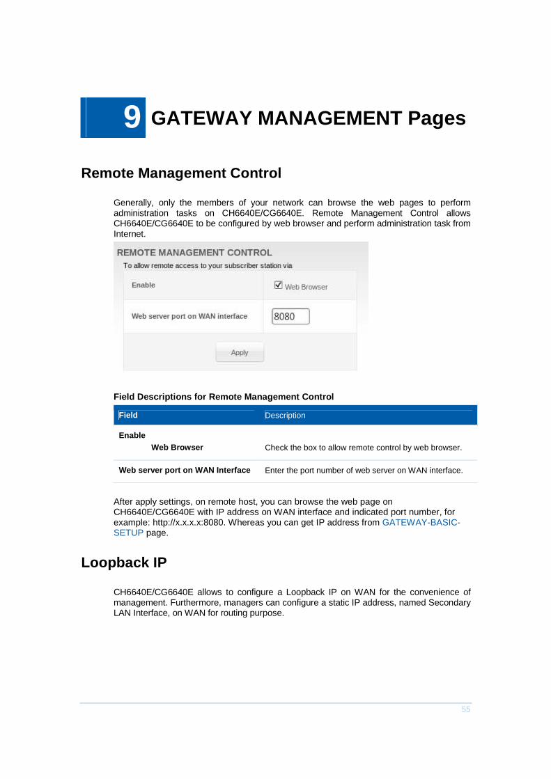
Remote Management Control
Generally, only the members of your network can browse the web pages to perform administration tasks on CH6640E/CG6640E. Remote Management Control allows CH6640E/CG6640E to be configured by web browser and perform administration task from Internet.
Field Descriptions for Remote Management Control
Field Description
Enable Web Browser
Check the box to allow remote control by web browser.
Web server port on WAN Interface Enter the port number of web server on WAN interface.
After apply settings, on remote host, you can browse the web page on CH6640E/CG6640E with IP address on WAN interface and indicated port number, for example: http://x.x.x.x:8080. Whereas you can get IP address from GATEWAY-BASIC-SETUP page.
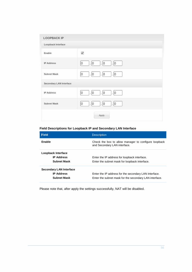
Loopback IP
CH6640E/CG6640E allows to configure a Loopback IP on WAN for the convenience of management. Furthermore, managers can configure a static IP address, named Secondary LAN Interface, on WAN for routing purpose.
56
Field Descriptions for Loopback IP and Secondary LA N Interface
Field Description
Enable Check the box to allow manager to configure loopback and Secondary LAN interface.
Loopback Interface IP Address Subnet Mask
Enter the IP address for loopback interface.
Enter the subnet mask for loopback interface.
Secondary LAN Interface IP Address Subnet Mask
Enter the IP address for the secondary LAN interface.
Enter the subnet mask for the secondary LAN interface.
Please note that, after apply the settings successfully, NAT will be disabled.
57
10 TELEPHONE Pages
The Multimedia Terminal Adapter (MTA) in your CH6640E provides digital VoIP services, which allow you to use the Internet to make telephone calls. Basic telephone functions, such as three-way calling, voice mail, and fax transmissions, can be supported with this connection on the CH6640E.
Click any TELEPHONE submenu option to view the status information for that option.
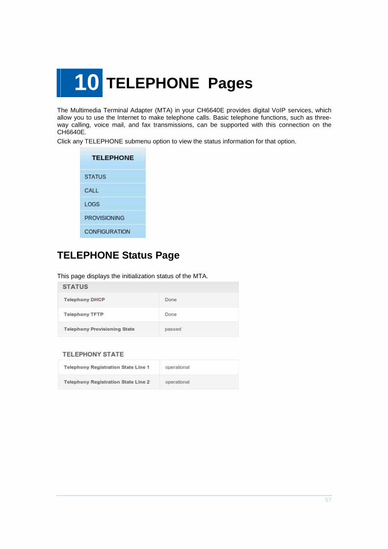
TELEPHONE Status Page
This page displays the initialization status of the MTA.
58
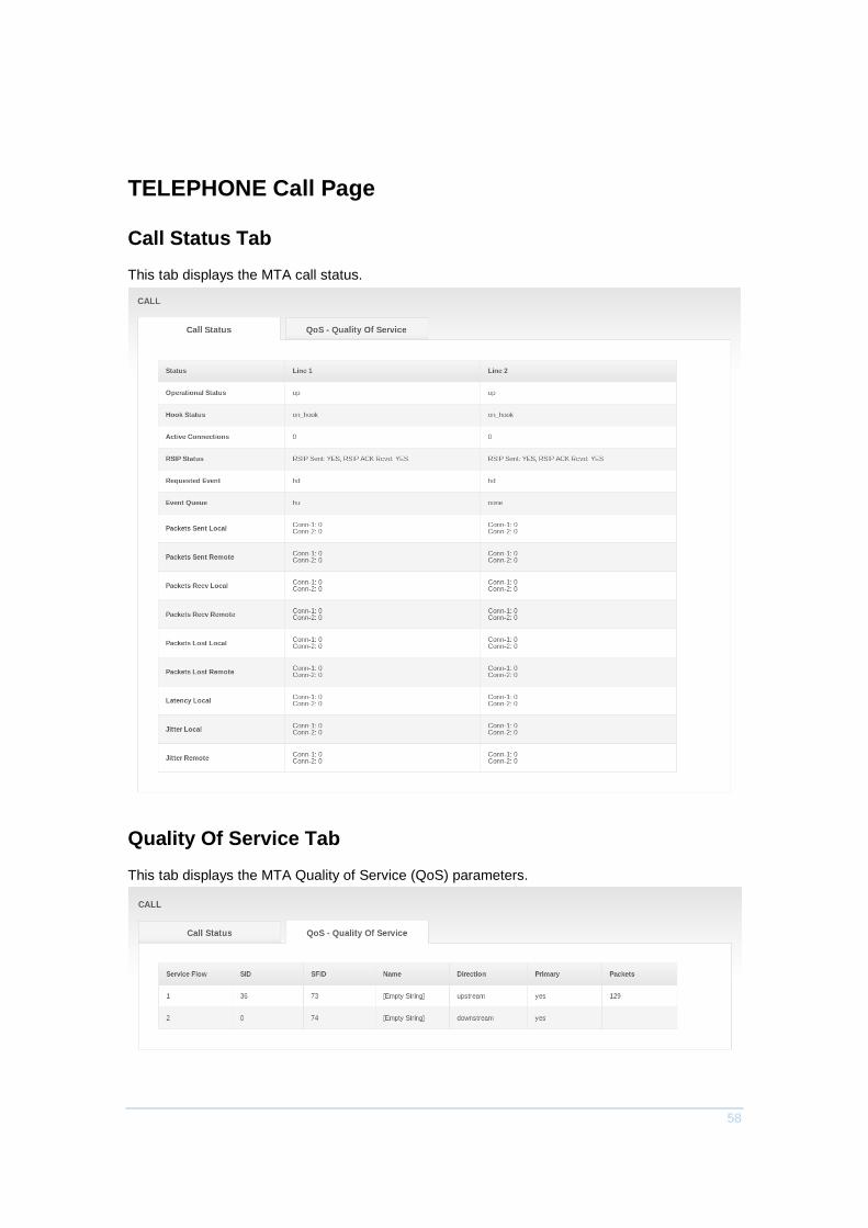
TELEPHONE Call Page
Call Status Tab
This tab displays the MTA call status.
Quality Of Service Tab
This tab displays the MTA Quality of Service (QoS) parameters.
59
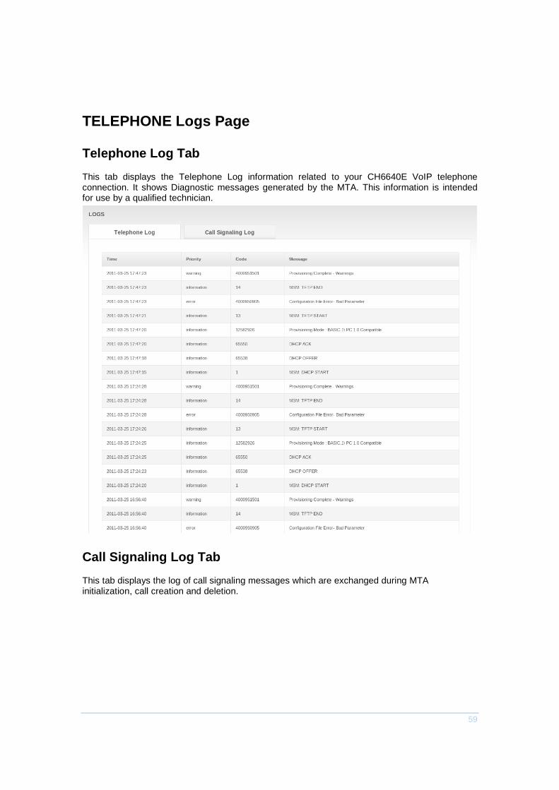
TELEPHONE Logs Page
Telephone Log Tab
This tab displays the Telephone Log information related to your CH6640E VoIP telephone connection. It shows Diagnostic messages generated by the MTA. This information is intended for use by a qualified technician.
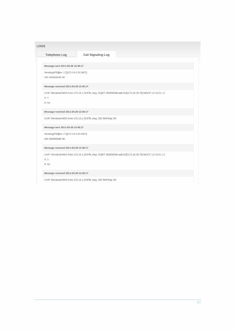
Call Signaling Log Tab
This tab displays the log of call signaling messages which are exchanged during MTA initialization, call creation and deletion.
60
61
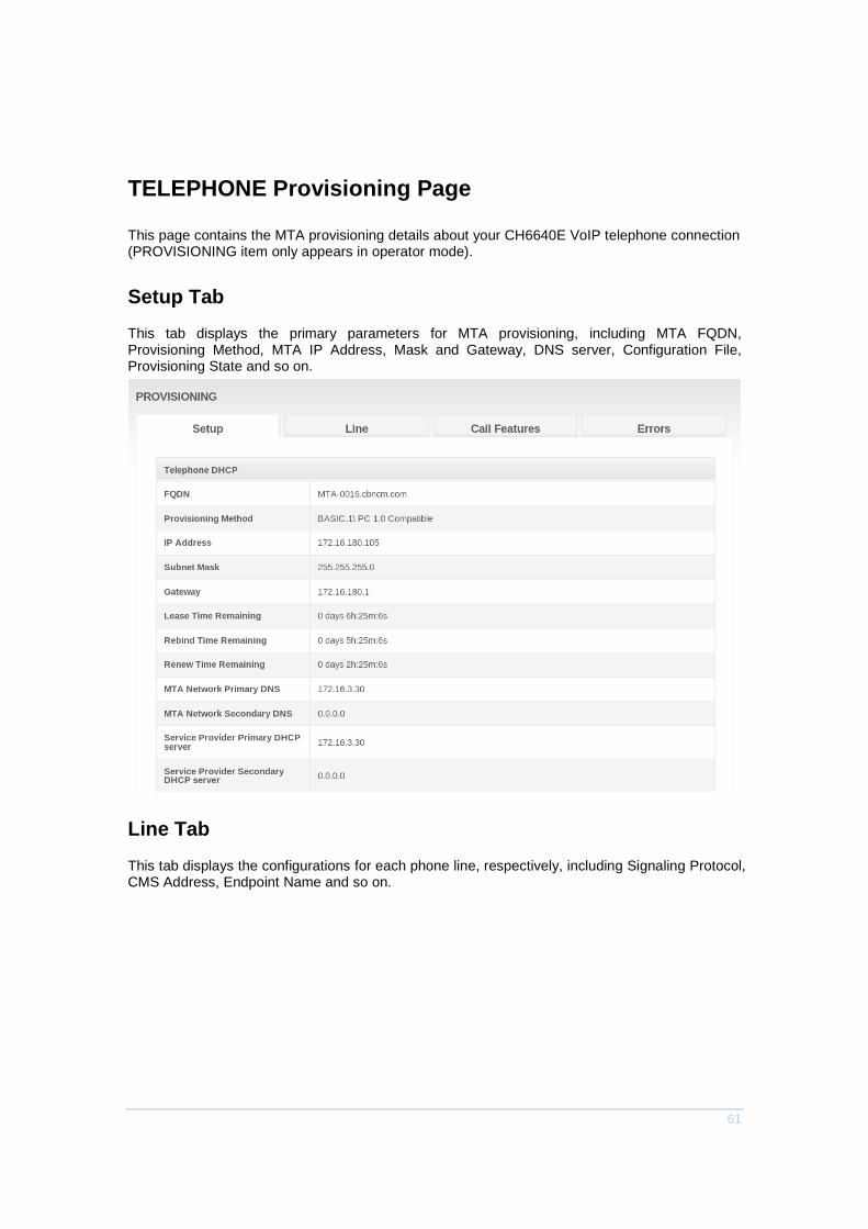
TELEPHONE Provisioning Page
This page contains the MTA provisioning details about your CH6640E VoIP telephone connection (PROVISIONING item only appears in operator mode).
Setup Tab
This tab displays the primary parameters for MTA provisioning, including MTA FQDN, Provisioning Method, MTA IP Address, Mask and Gateway, DNS server, Configuration File, Provisioning State and so on.
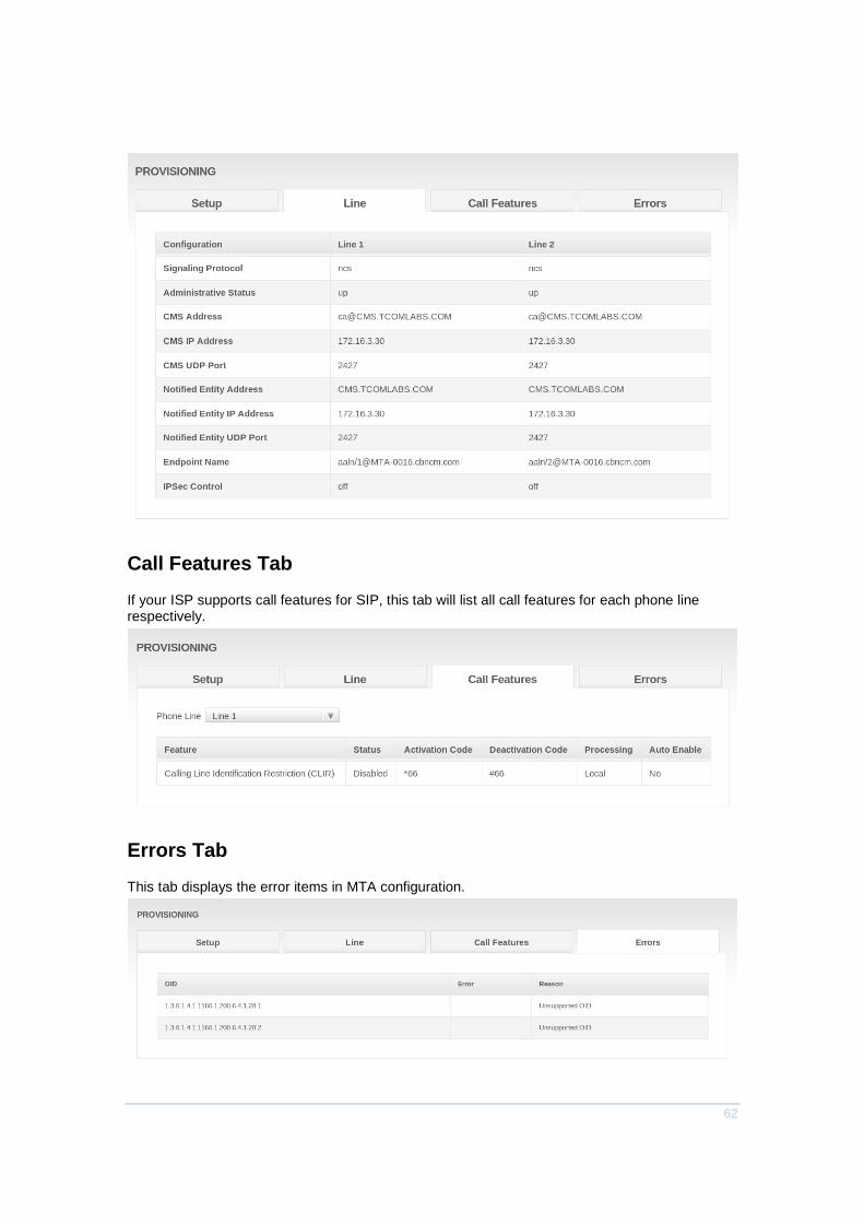
Line Tab
This tab displays the configurations for each phone line, respectively, including Signaling Protocol, CMS Address, Endpoint Name and so on.
62
Call Features Tab
If your ISP supports call features for SIP, this tab will list all call features for each phone line respectively.
Errors Tab
This tab displays the error items in MTA configuration.
63
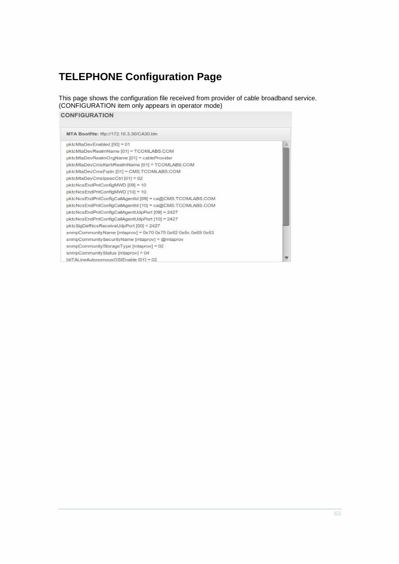
TELEPHONE Configuration Page
This page shows the configuration file received from provider of cable broadband service. (CONFIGURATION item only appears in operator mode)
64
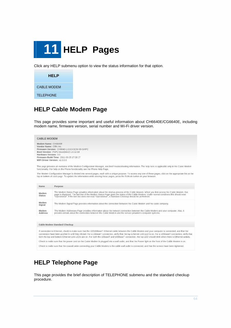
11 HELP Pages
Click any HELP submenu option to view the status information for that option.
HELP Cable Modem Page
This page provides some important and useful information about CH6640E/CG6640E, including modem name, firmware version, serial number and Wi-Fi driver version.
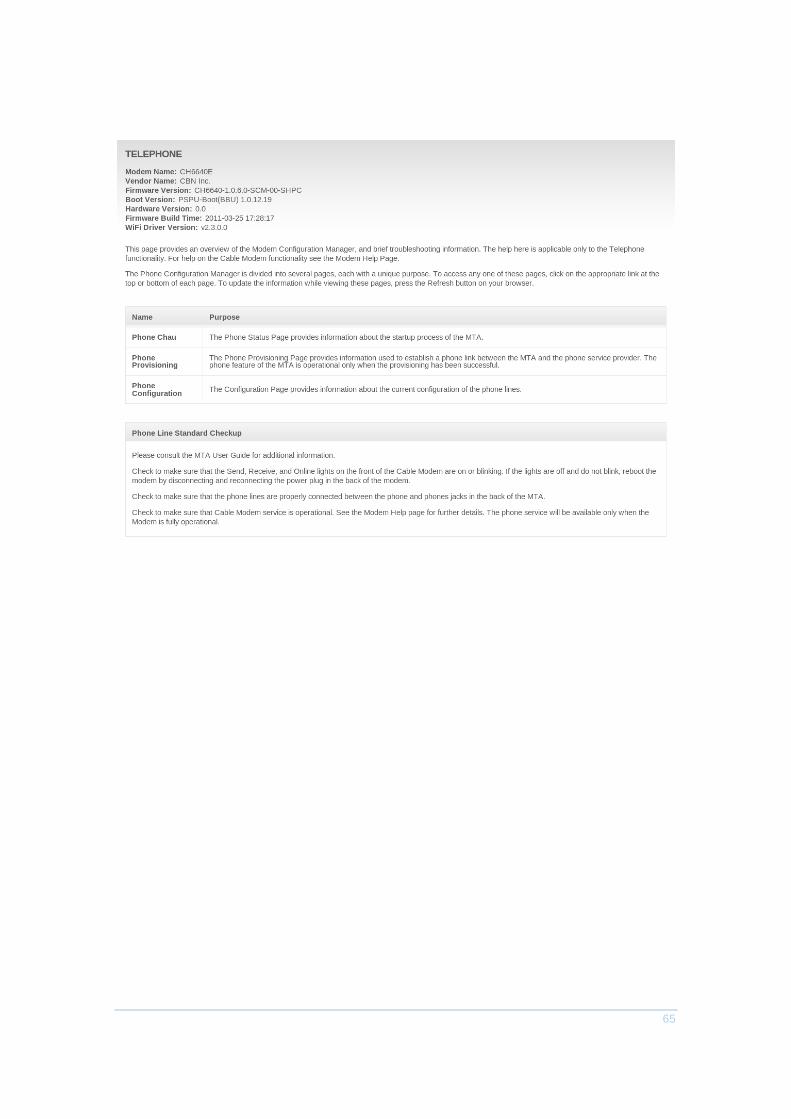
HELP Telephone Page
This page provides the brief description of TELEPHONE submenu and the standard checkup procedure.
65
66
12 Troubleshooting
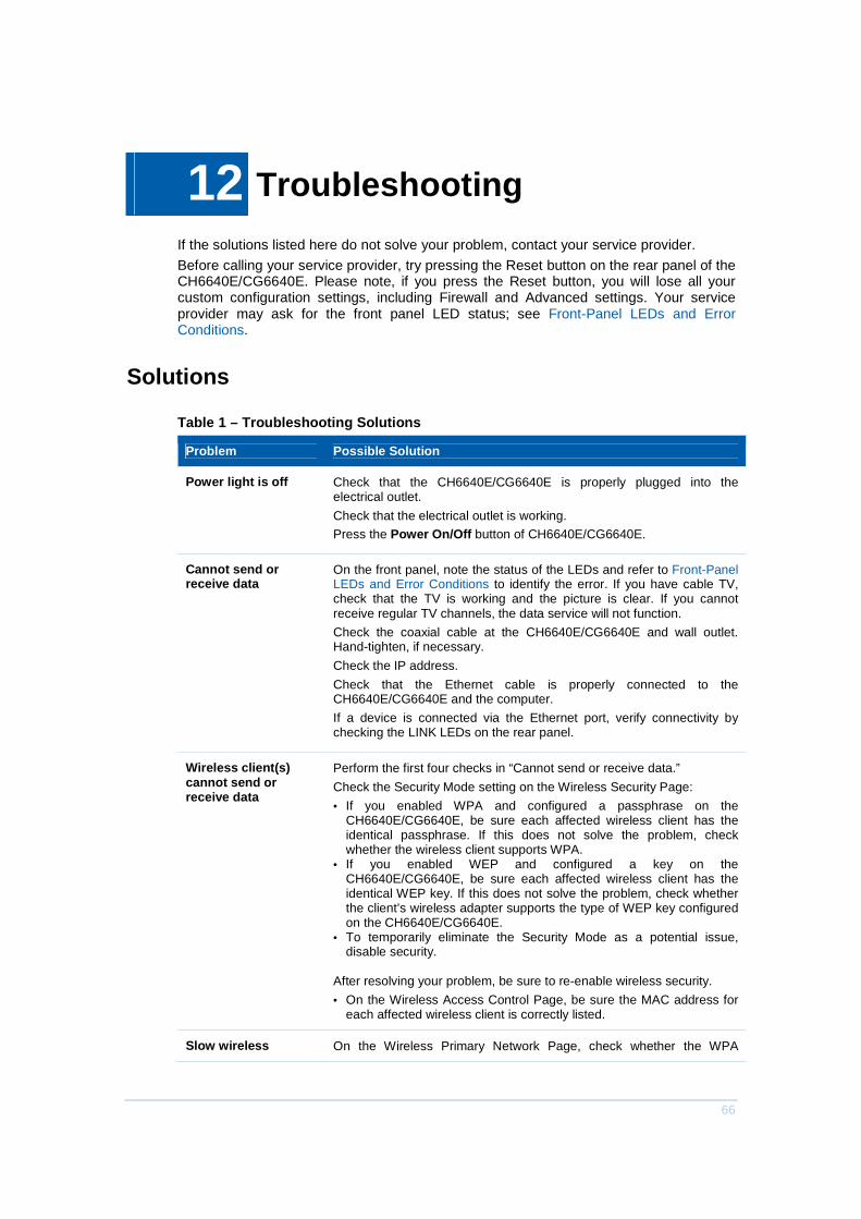
If the solutions listed here do not solve your problem, contact your service provider.
Before calling your service provider, try pressing the Reset button on the rear panel of the CH6640E/CG6640E. Please note, if you press the Reset button, you will lose all your custom configuration settings, including Firewall and Advanced settings. Your service provider may ask for the front panel LED status; see Front-Panel LEDs and Error Conditions.
Solutions
Table 1 – Troubleshooting Solutions
Problem Possible Solution
Power light is off Check that the CH6640E/CG6640E is properly plugged into the electrical outlet.
Check that the electrical outlet is working.
Press the Power On/Off button of CH6640E/CG6640E.
Cannot send or receive data
On the front panel, note the status of the LEDs and refer to Front-Panel LEDs and Error Conditions to identify the error. If you have cable TV, check that the TV is working and the picture is clear. If you cannot receive regular TV channels, the data service will not function.
Check the coaxial cable at the CH6640E/CG6640E and wall outlet. Hand-tighten, if necessary.
Check the IP address.
Check that the Ethernet cable is properly connected to the CH6640E/CG6640E and the computer.
If a device is connected via the Ethernet port, verify connectivity by checking the LINK LEDs on the rear panel.
Wireless client(s) cannot send or receive data
Perform the first four checks in “Cannot send or receive data.”
Check the Security Mode setting on the Wireless Security Page:
• If you enabled WPA and configured a passphrase on the CH6640E/CG6640E, be sure each affected wireless client has the identical passphrase. If this does not solve the problem, check whether the wireless client supports WPA.
• If you enabled WEP and configured a key on the CH6640E/CG6640E, be sure each affected wireless client has the identical WEP key. If this does not solve the problem, check whether the client’s wireless adapter supports the type of WEP key configured on the CH6640E/CG6640E.
• To temporarily eliminate the Security Mode as a potential issue, disable security.
After resolving your problem, be sure to re-enable wireless security.
• On the Wireless Access Control Page, be sure the MAC address for each affected wireless client is correctly listed.
Slow wireless On the Wireless Primary Network Page, check whether the WPA
67
Problem Possible Solution
transmission speed with WPA enabled
Encryption type is TKIP. If all of your wireless clients support AES, change the WPA Encryption to AES.
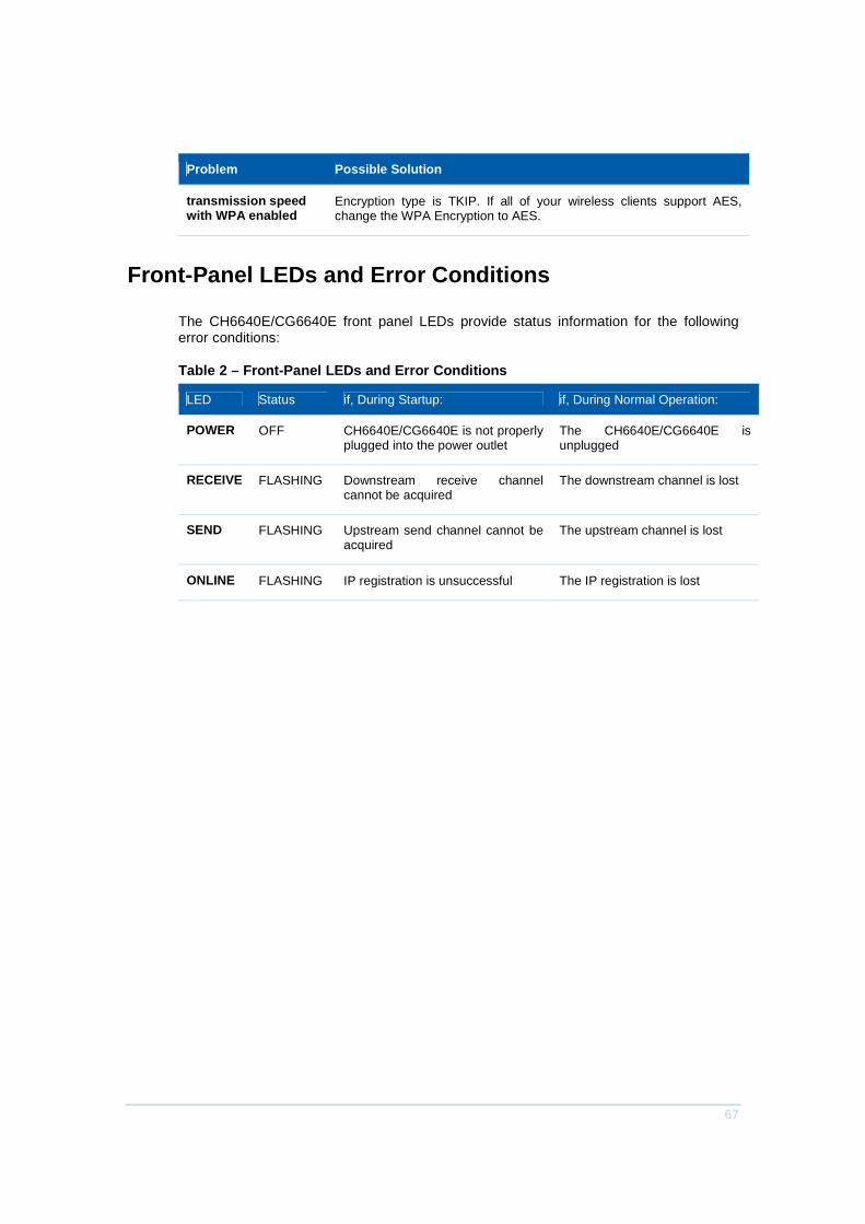
Front-Panel LEDs and Error Conditions
The CH6640E/CG6640E front panel LEDs provide status information for the following error conditions:
Table 2 – Front-Panel LEDs and Error Conditions
LED Status if, During Startup: if, During Normal Operation:
POWER OFF CH6640E/CG6640E is not properly plugged into the power outlet
The CH6640E/CG6640E is unplugged
RECEIVE FLASHING Downstream receive channel cannot be acquired
The downstream channel is lost
SEND FLASHING Upstream send channel cannot be acquired
The upstream channel is lost
ONLINE FLASHING IP registration is unsuccessful The IP registration is lost


