COMPANY PROFILE Vontron Technology Co., Ltd. is specialized in R&D, manufacture and technical service of RO and NF membrane elements. Owning the core technology and capability for fabrication of membrane sheet, Vontron is the biggest professional manufacturer of compound RO membranes in China, and is the provider of system design and applied service with powerful technical support. Vontron operates its manufacturing plant in both Beijing and Guiyang, with total capacity of 7.5 million square meters of RO and NF membrane sheet annually. Based upon the absorption and renovation of the full-process RO membrane producing line and technologies imported from the United States in 2001, the product series produced by Vontron, including industrial-purpose element, seawater desalination element, fouling resistant element, oxidation resistant element and residential element, etc., have taken the leading position in quality and technological level in the world. Vontron has become the world’s second supplier of dry-type membrane elements with capacity of mass production. Moreover, the oxidation-resistant membrane and fouling-resistant membrane with leading technical advantage under completely independent intellectual property developed by Vontron have been widely applied to the wastewater treatment field, and have surmounted the difficulty in the application of RO membranes, i.e. the organic contamination and biological contamination, and have been widely applied in foodstuff and hygiene industries such as pharmaceutical abstraction, germ-free drinking water, etc. The company has been undertaking a number of state-level and province/ministry level projects, including National 863 Program, National Torch Program and National New Product Program, etc. The company applied for 11 state-level patents in 2001, including compound oxidation resistant RO membrane, laser thermal-melting equipment, etc. The R&D team, consisting mainly of doctorial researchers, has established four professionalized basic platforms separately of “design, research & development”, “technological process control”, “inspection and test”, and “applied research”, thus building a solid technical foundation for rapid growth in the future. Vontron has accomplished developing various specifications of compound RO membranes covering 8 series and more than 40 models. All product series adopt the state-of-the-art fouling- resistant technology, and reach the international advanced level in quality. Certified to NSF Standards, VONTRON TM membranes have been broadly applied to seawater desalination, purification of drinking water, depuration of sewage and concentration/abstraction, and well sold to Italy, Spain, Germany, Turkey, Korea, Japan, Vietnam, Malaysia, Thailand, Singapore, Brazil, etc., where Vontron has also set up its sales distributors and consistent customers Vontron will be, as always, carrying out the corporate spirit of “Surmounting ourselves and pursuing endlessly”, bringing forth the new products from the old ones, and devoting ourselves to the establishment of elite products for the enviro-tech era.
Transcript
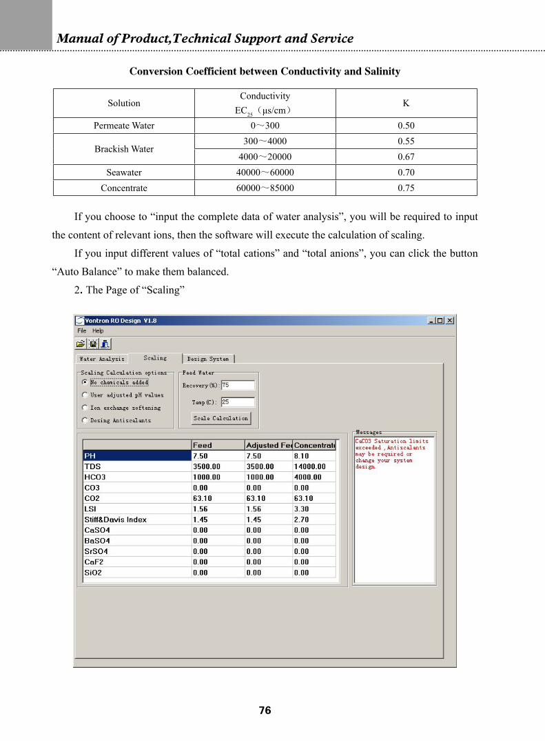
�
COMPANY PROFILE
Vontron Technology Co., Ltd. is specialized in R&D, manufacture and technical service of RO and NF membrane elements. Owning the core technology and capability for fabrication of membrane sheet, Vontron is the biggest professional manufacturer of compound RO membranes in China, and is the provider of system design and applied service with powerful technical support.
Vontron operates its manufacturing plant in both Beijing and Guiyang, with total capacity of 7.5 million square meters of RO and NF membrane sheet annually.
Based upon the absorption and renovation of the full-process RO membrane producing line and technologies imported from the United States in 2001, the product series produced by Vontron, including industrial-purpose element, seawater desalination element, fouling resistant element, oxidation resistant element and residential element, etc., have taken the leading position in quality and technological level in the world. Vontron has become the world’s second supplier of dry-type membrane elements with capacity of mass production. Moreover, the oxidation-resistant membrane and fouling-resistant membrane with leading technical advantage under completely independent intellectual property developed by Vontron have been widely applied to the wastewater treatment field, and have surmounted the difficulty in the application of RO membranes, i.e. the organic contamination and biological contamination, and have been widely applied in foodstuff and hygiene industries such as pharmaceutical abstraction, germ-free drinking water, etc.
The company has been undertaking a number of state-level and province/ministry level projects, including National 863 Program, National Torch Program and National New Product Program, etc. The company applied for 11 state-level patents in 2001, including compound oxidation resistant RO membrane, laser thermal-melting equipment, etc. The R&D team, consisting mainly of doctorial researchers, has established four professionalized basic platforms separately of “design, research & development”, “technological process control”, “inspection and test”, and “applied research”, thus building a solid technical foundation for rapid growth in the future.
Vontron has accomplished developing various specifications of compound RO membranes covering 8 series and more than 40 models. All product series adopt the state-of-the-art fouling-resistant technology, and reach the international advanced level in quality. Certified to NSF Standards, VONTRONTM membranes have been broadly applied to seawater desalination, purification of drinking water, depuration of sewage and concentration/abstraction, and well sold to Italy, Spain, Germany, Turkey, Korea, Japan, Vietnam, Malaysia, Thailand, Singapore, Brazil, etc., where Vontron has also set up its sales distributors and consistent customers
Vontron will be, as always, carrying out the corporate spirit of “Surmounting ourselves and pursuing endlessly”, bringing forth the new products from the old ones, and devoting ourselves to the establishment of elite products for the enviro-tech era.
�
Manual of Product,Technical Support and Service
Company Profile…………………………………………………………………………………1
Contents……………………………………………………………………………………………2
PART ONE: TECHNICAL SPECIFICATIONS
Chapter I-Introduction to VONTRONTM RO Membranes1-1 Major Membrane Product Series…………………………………………………………7
1-2 Nomenclature of VONTRON Membrane Elements……………………………………9
1-3 Catalog and Selection of VONTRONTM Membrane Elements………………………11
1-3.1 Catalog of Industrial Membrane Elements…………………………………………11
1-3.2 Catalog of Residential Membranes and Non-standard Membranes…………………12
1-3.3 Catalog of Nanofiltration Membranes………………………………………………13
1-3.4 Guide to Selection of Membrane Elements…………………………………………14
1-4 Complete Series of VONTRONTM Dry Membrane Elements………………………15
1-4.1 Comparison between Dry-type and Wet-type Membrane Elements…………………15
1-4.2 Precautions for Use of Dry-type Membrane Elements………………………………15
Chapter II-General Technical Specifications of
VONTRONTM RO Membranes2-1 VONTRONTM Residential and Non-standard RO Element…………………………17
Chapter IV-Guide to Design of RO System 4-1 Design of Pretreatment Section of RO System………………………………………434-1.1 Analysis of Type and Quality of Raw Water…………………………………………434-1.2 Water Treatment Processes Frequently Used in RO Pretreatment……………………51 4-1.3 Comparison of Common Pretreatment Processes for Regular
RO Membrane and Oxidation Resistant RO Membrane……………………………644-2 Design of RO Filtration System………………………………………………………66 4-2.1 Guide to Design of VONTRON Membrane Element………………………………664-2.2 Design Steps for RO System…………………………………………………………674-2.3 Other Considerations in Design of Membrane System……………………………70 4-3 Instructions for Use of RO Design Software…………………………………………744-4 Design of Chemical Cleaning Section of RO Membrane System……………………82
Chapter V-Guide to Use and Maintenance of RO System5-1 Initial Adjustment of RO System……………………………………………………845-1.1 Installation and Disassembly of Membrane Element………………………………845-1.2 Operating Steps and Methods for Initial Running of RO System…………………865-2 Routine Operation and Maintenance of RO System…………………………………885-2.1 Records of Running of RO System…………………………………………………885-2.2 Routine Startup and Shutdown of RO Membrane System…………………………915-3 Management of RO System during Shutdown Period………………………………925-3.1 Management for Routine Shutdown (0~48 hours)…………………………………925-3.2 Management for System Shutdown (2~25 Days)…………………………………925-3.3 Management for Long-term Shutdown of System (more than 25 days)……………935-3.4 Preservation and Management of Membrane Element Taken out from
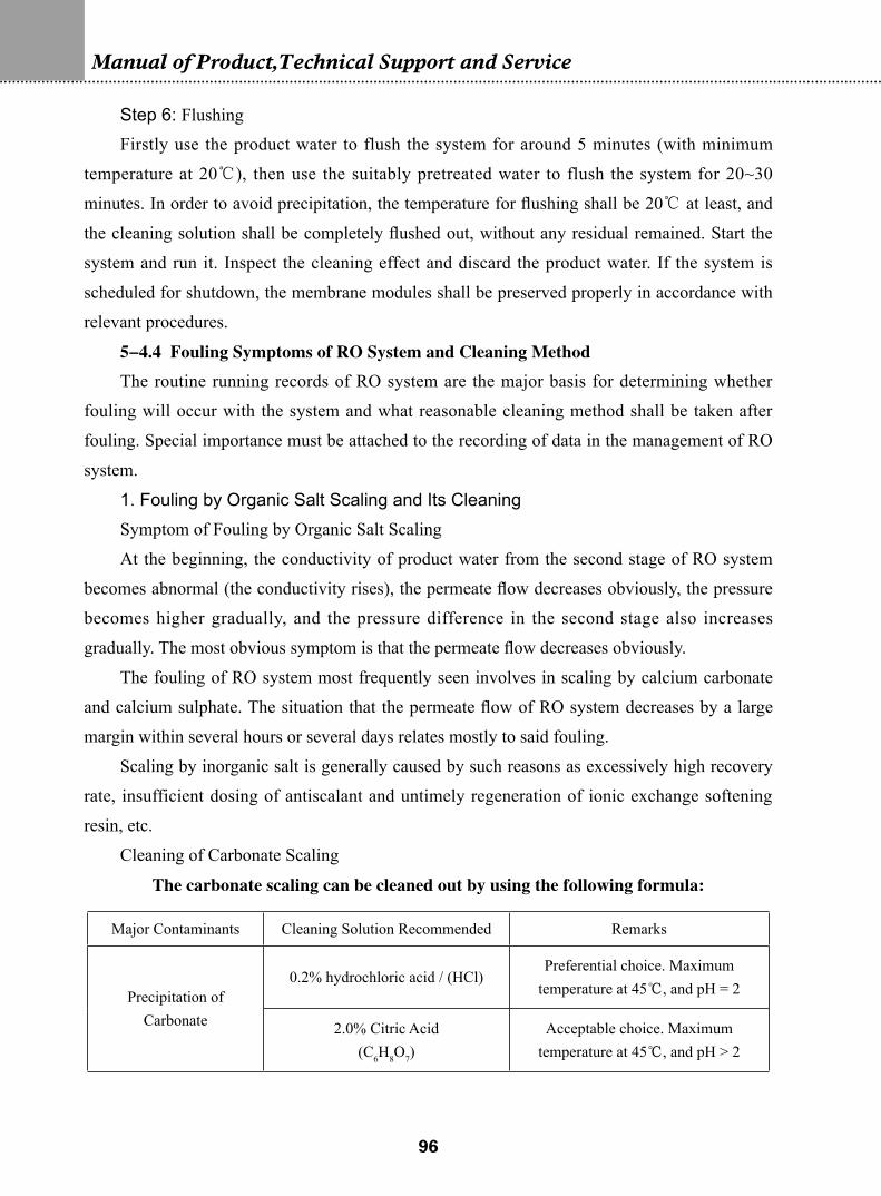
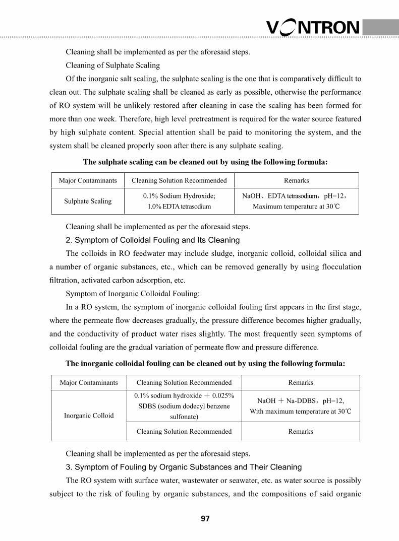
System during Shutdown……………………………………………………………935-4 Guide to Cleaning of RO System……………………………………………………935-4.1 Brief Introduction of Fouling of Membrane Element………………………………935-4.2 Judgement of Cleaning Time for RO System………………………………………945-4.3 Steps of Cleaning of RO System……………………………………………………945-4.4 Fouling Symptoms of RO System and Cleaning Method…………………………96
Chapter VI-Troubleshooting of RO System6-1 Troubleshooting of RO System During the Initial Running (Adjustment) Period……1016-1.1 Low Permeate Flow and High Pressure……………………………………………101
�
Manual of Product,Technical Support and Service
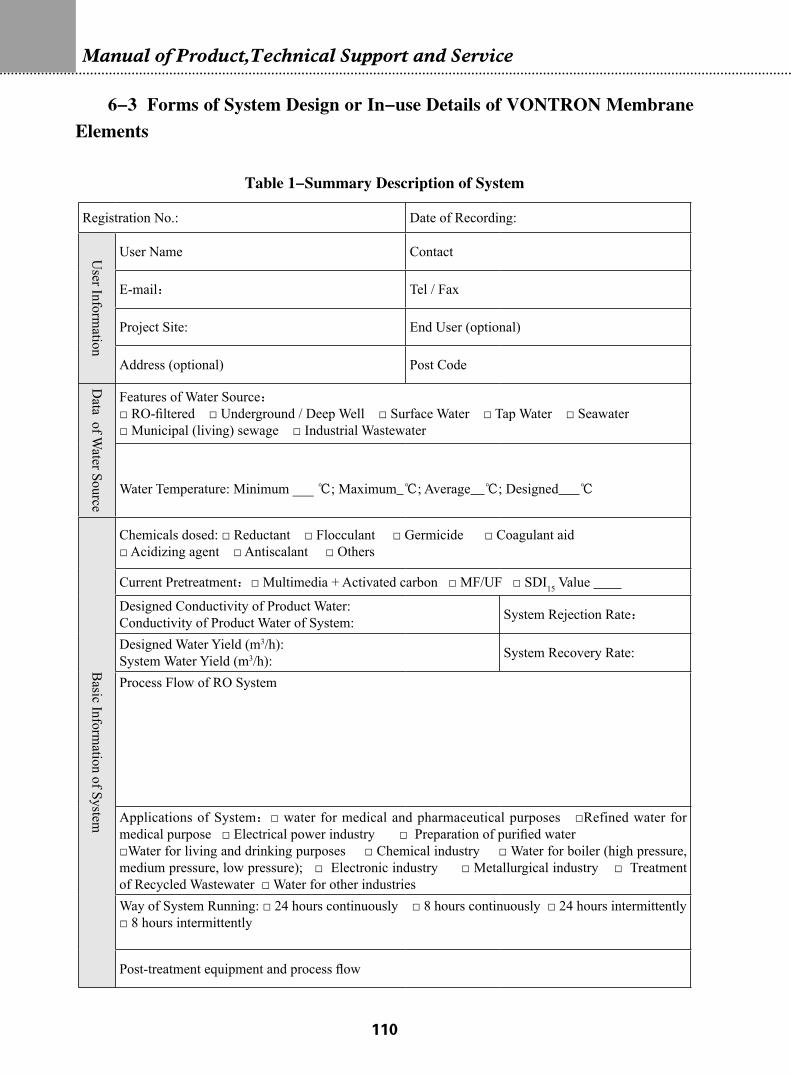
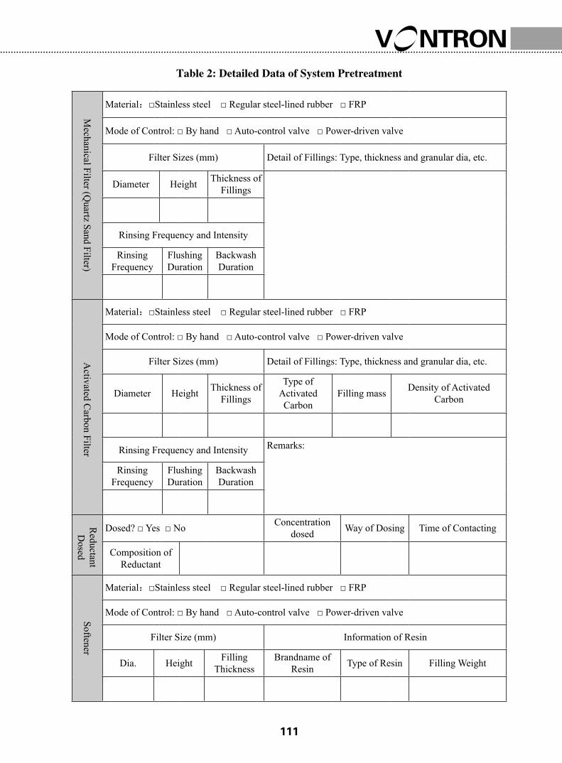
6-1.2 Low Rejection Rate and High Conductivity of Product Water……………………1026-2 Troubleshooting of Failures of RO System Occurring after Regular Running………1036-3 Forms of System Design or In-use Details of VONTRON Membrane Elements……110Table 1 – Summary Description of System………………………………………………110Table 2: Detailed Data of System Pretreatment……………………………………………111Table 3: Data of Raw Water Quality of RO System………………………………………112
PART TWO: SERVICE INSTRUCTIONS
Chapter VII-Quality Assurance of VONTRON Membrane Elements7-1 Three-year Warranty for RO Membrane Elements…………………………………1157-2 Procedures for Repair and Replacement of Membrane Element……………………1197-2.1 Procedure on Repair of Membrane Element………………………………………1197-2.2 Packing and Transportation………………………………………………………1207-2.3 Procedures for Inspection and Testing………………………………………………1207-2.4 Additional Provisions………………………………………………………………1207-3 Quality Certification…………………………………………………………………122
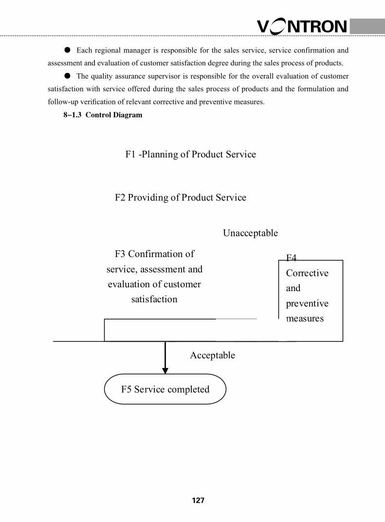
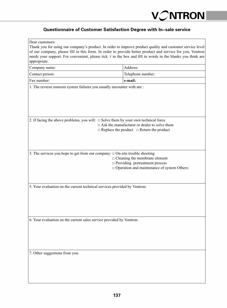
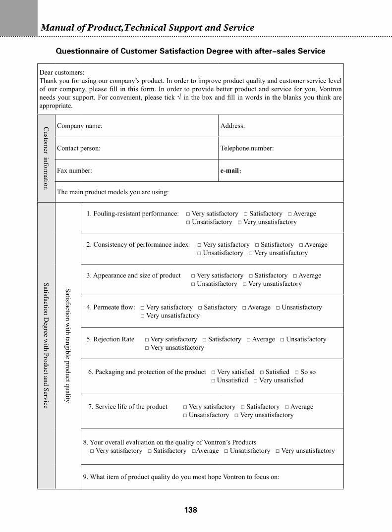
Chapter VIII-Specifications on Service of Membrane Elements8-1 Control Procedure on Service………………………………………………………1268-1.1 Subject Content and Application Range……………………………………………1268-1.2 Function and Responsibility………………………………………………………1268-1.3 Control Diagram……………………………………………………………………1278-1.4 Control Procedure…………………………………………………………………1288-2 Requirements on the Content and Procedure of Pre-sales Service…………………1318-3 Requirements on the Content and Procedure of In-sale Service……………………1318-4 Requirements for the Content and Providing of After-sales Service…………………132
Chapter IX-Guide for Assessment and Evaluation of Customer Satisfaction Degree
9-1 Mode of Assessment and Evaluation…………………………………………………134 9-2 Scope of Assessment and Evaluation…………………………………………………134 9-3 Content of Assessment and Evaluation………………………………………………1349-4 Improvement…………………………………………………………………………135
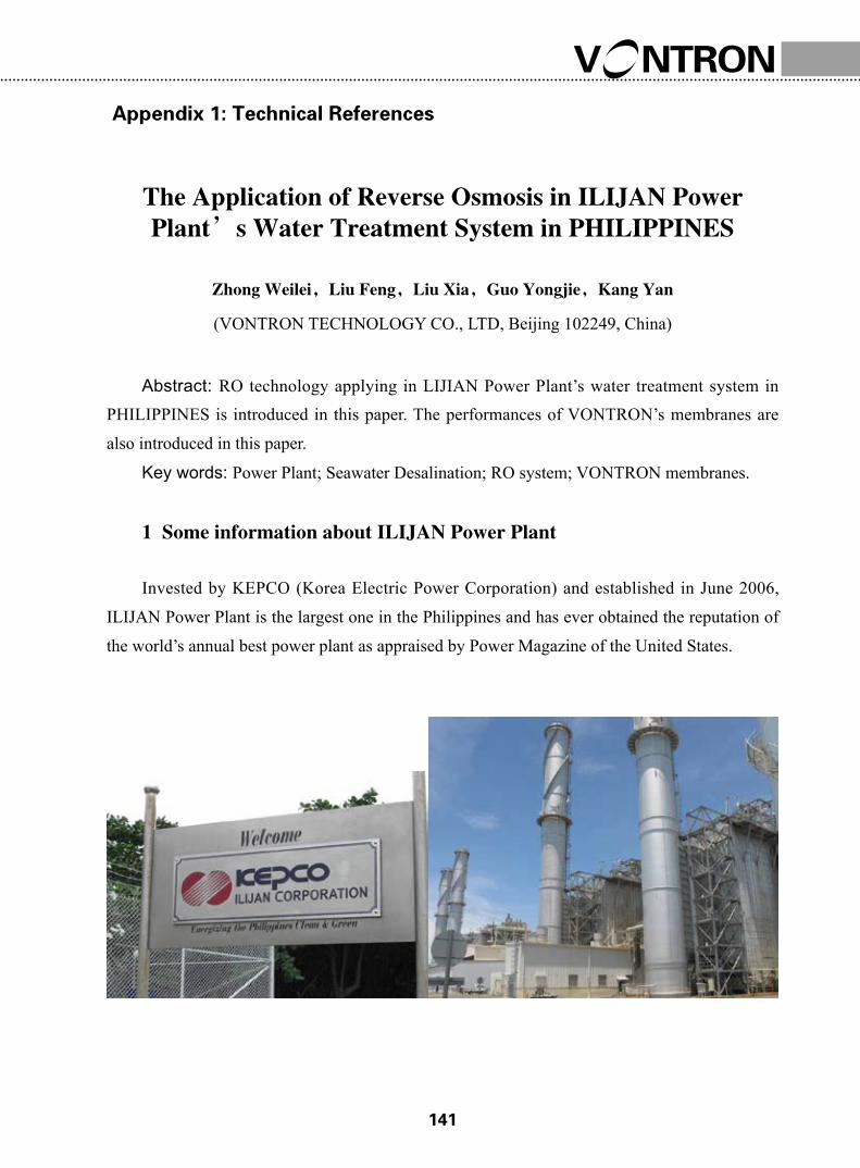
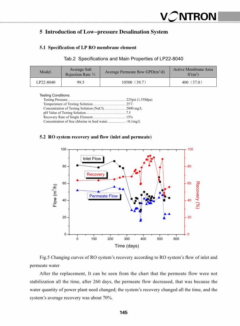
Appendix 1: Technical ReferencesThe Application of Reverse Osmosis in ILIJAN Power Plant’s Water Treatment System in PHILIPPINES………………………………………………141
Appendix 2: Temperature Correction Factors for Permeate Flow……………148
�
PART ONE: TECHINICAL
SPECIFICATIONS
�
Manual of Product,Technical Support and Service
�
1-1 Major Membrane Product Series
◇ Residential Membrane Element: 1812-sized and 2012-sized
The 1812-sized and 2012-sized residential membrane elements are mainly applicable to
various small-sized systems, such as household water purifier and other water purifying devices
in hospital and laboratory.
◇XLP Series: Extremely Low Pressure Compound RO Membrane Element
Working under the conditions of extremely low operating pressure, XLP membrane series
can achieve as high permeated flow and rejection rate as regular low-pressure membranes can.
It runs under approximately half pressure of that of regular low pressure compound membranes,
and can achieve a rejection rate of as high as 98.0%.
◇ ULP Series: Ultra-low Pressure Compound RO Membrane Element
Working under the conditions of ultra low operating pressure, ULP membrane series can
achieve as high permeated flow and rejection rate as regular low-pressure membranes can.
It runs under approximately two thirds pressure of that of regular low pressure compound
membranes, and can achieve a rejection rate of as high as 98.0%.
◇ LP Series: Low Pressure Compound RO Membrane Element
Having the properties of low-pressure, high permeated flow and excellent desalination
performance, LP membrane series is mainly applicable to brackish water desalination.
Furthermore, with the excellent properties in removing soluble salts, TOC and SiO2, it is
particularly applicable to preparation of high-purity water for electronic and electrical power
industries.
◇ SW Series: Compound RO Membrane Element for Seawater Desalination
Designed for sweater desalination, the SW series can increase the permeated flow by
improving the structure of membrane elements, thus decreasing the number of membrane
elements installed. It has the properties of high rejection rate, persistent performance, low
operation cost and low investment in equipment, and can ensure that drinking water can be
produced from seawater simply by one-pass RO treatment.
◇ FR Series: Fouling Resistant Compound RO Membrane Element
FR membrane series is mainly applied to reuse of wastewater and treatment of high-
Chapter I-Introduction to VONTRONTM RO Membranes
�
Manual of Product,Technical Support and Service
polluted surface water. For treatment of water with inferior quality grade, it adopts the design
of wider feedwater inflow conduit net, which makes it easier to be cleaned. Furthermore, the
membrane surface has been specially processed with special technology, thus changing the
electric charge and the smoothness of membrane surface, increasing the hydrophilicity of
membrane surface, reducing the contaminants and microbes adhering to the membrane surface,
bringing about the performance of stronger resistant to scaling, organic contamination and
microbe contamination, and therefore decreasing the contamination speed of membrane element
and elongating its service life.
◇ HOR Series: High Oxidation Resistant RO Membrane Element
The HOR series, independently developed Vontron Technology Co., Ltd. upon years of
research, is currently the sole oxidation resistant RO membrane in the world, and is mainly
applied to treatment of wastewater reuse, surface water with high microbe contamination,
and feedwater containing oxidative substances as well as applied to germ-free system, etc.
Considering the shortcoming of regular polyamide RO membrane in weak resistance to
oxidation, the HOR series has integrated special synthetic process to strengthen the oxidation
resistance of membrane element, and allow the bactericide to be directly dispensed to the
membrane element so as to keep the RO mainframe completely free of bacteria. The use of HOR
membrane elements can simplify and optimize the pretreatment process of RO system (without
filtration by activated carbon or dispensing of reductant), thus saving the investment cost and
therefore reducing the microbial contamination of membrane element, saving the operational
cost and elongating the service life.
◇ VNF Series: Nanofiltation Element
Nanofiltration element is used for purification of drinking water and industrial-purpose
water, treatment of wastewater and concentration of valuable ingredients in industrial fluids.
It can detain those substances with molecular weight between 200~1000 and separate those
substances with molecular dimension of 1nm from the solution.
�
1-2 Nomenclature of VONTRONTM Membrane Elements
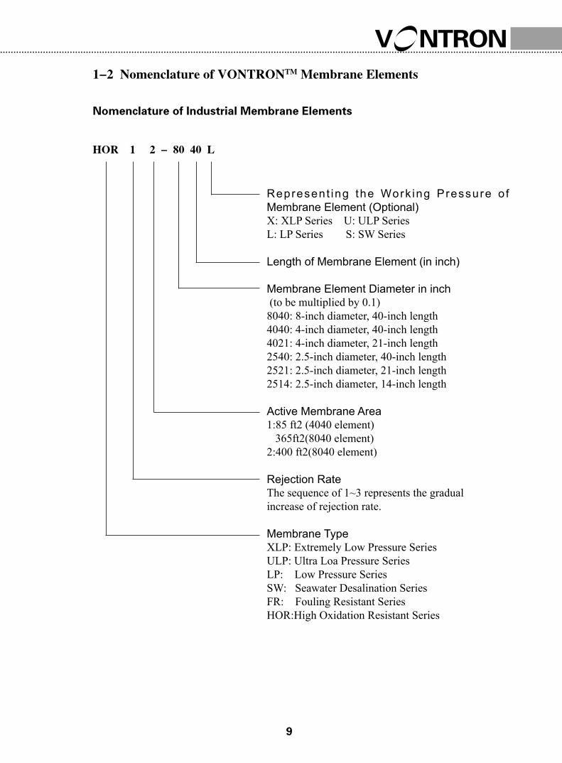
Nomenclature of Industrial Membrane Elements
HOR 1 2 - 80 40 L
Represent ing the Work ing Pressure o f Membrane Element (Optional) X: XLP Series U: ULP SeriesL: LP Series S: SW Series
Length of Membrane Element (in inch)
Membrane Element Diameter in inch (to be multiplied by 0.1)8040: 8-inch diameter, 40-inch length4040: 4-inch diameter, 40-inch length4021: 4-inch diameter, 21-inch length2540: 2.5-inch diameter, 40-inch length2521: 2.5-inch diameter, 21-inch length2514: 2.5-inch diameter, 14-inch length
Active Membrane Area1:85 ft2 (4040 element) 365ft2(8040 element)2:400 ft2(8040 element)
Rejection RateThe sequence of 1~3 represents the gradual increase of rejection rate.
Membrane TypeXLP: Extremely Low Pressure SeriesULP: Ultra Loa Pressure Series LP: Low Pressure SeriesSW: Seawater Desalination SeriesFR: Fouling Resistant SeriesHOR:High Oxidation Resistant Series
�0
Manual of Product,Technical Support and Service
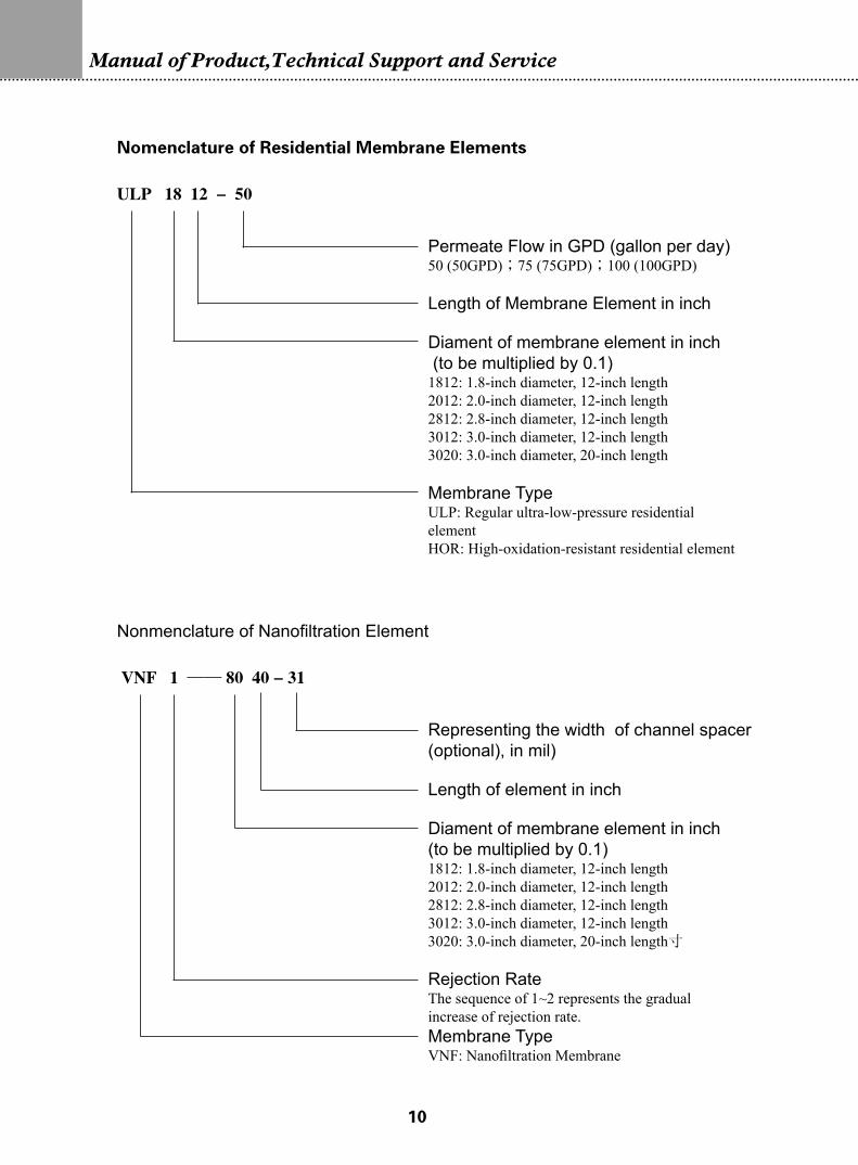
Nomenclature of Residential Membrane Elements
Permeate Flow in GPD (gallon per day)50 (50GPD);75 (75GPD);100 (100GPD)
Length of Membrane Element in inch
Diament of membrane element in inch (to be multiplied by 0.1)1812: 1.8-inch diameter, 12-inch length2012: 2.0-inch diameter, 12-inch length2812: 2.8-inch diameter, 12-inch length3012: 3.0-inch diameter, 12-inch length3020: 3.0-inch diameter, 20-inch length
Membrane TypeULP: Regular ultra-low-pressure residential elementHOR: High-oxidation-resistant residential element
ULP 18 12 - 50
Nonmenclature of Nanofiltration Element
Representing the width of channel spacer (optional), in mil) Length of element in inch
Diament of membrane element in inch (to be multiplied by 0.1)1812: 1.8-inch diameter, 12-inch length2012: 2.0-inch diameter, 12-inch length2812: 2.8-inch diameter, 12-inch length3012: 3.0-inch diameter, 12-inch length3020: 3.0-inch diameter, 20-inch length寸
Rejection RateThe sequence of 1~2 represents the gradual increase of rejection rate.Membrane TypeVNF: Nanofiltration Membrane
VNF 1 —— 80 40 - 31
��
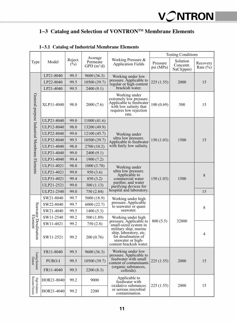
1-3 Catalog and Selection of VONTRONTM Membrane Elements
1-3.1 Catalog of Industrial Membrane Elements
Type Model Reject.(%)
Average Permeate
GPD (m3/d)Working Pressure & Application Fields
Testing Conditions
Pressurepsi (MPa)
Solution Concentr.
NaCl(ppm)Recovery Rate (%)
General-purpose Industrial M
embrane Elem
ents
LP21-8040 99.5 9600 (36.3) Working under low pressure. Applicable to regular or high content
8SW22-8040 99.7 6000 (22.7)SW21-4040 99.5 1400 (5.3)SW11-2540 99.2 500 (1.89) Working under high
pressure. Applicable to small-sized system in military ship, marine ship, laboratory, etc. for desalination of seawater or high-
content brackish water.
SW11-4021 99.2 750 (2.8)
4SW11-2521 99.2 200 (0.76)
Fouling Resistant Element
FR11-8040 99.5 9600 (36.3) Working under low pressure. Applicable to feedwater with small
content of contaminants (organic substances,
colloids).
225 (1.55) 2000 15PURO-I 99.5 10500 (39.7)
FR11-4040 99.5 2200 (8.3)
High Oxidation Resistant Element
HOR21-8040 99.2 9000 Applicable to feedwater with
oxidative substances or serious microbial
contamination.
225 (1.55) 2000 15HOR21-4040 99.2 2200
��
Manual of Product,Technical Support and Service
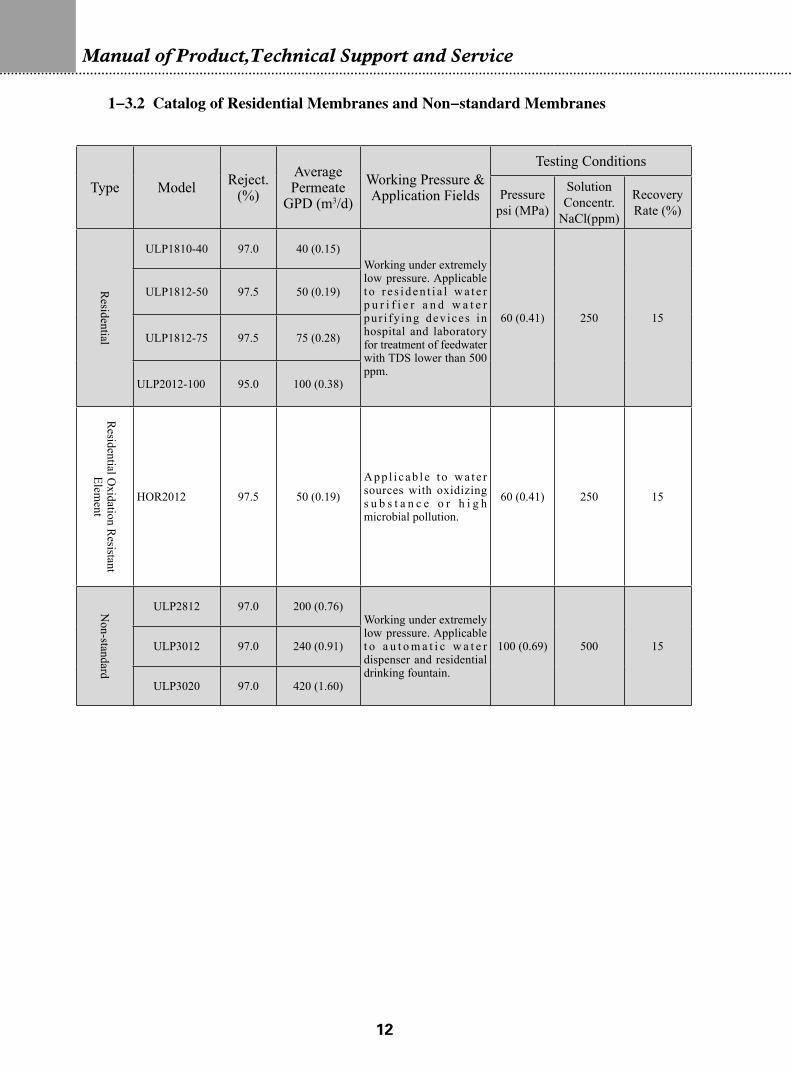
1-3.2 Catalog of Residential Membranes and Non-standard Membranes
Type Model Reject.(%)
Average Permeate
GPD (m3/d)Working Pressure & Application Fields
Testing Conditions
Pressurepsi (MPa)
Solution Concentr.
NaCl(ppm)
Recovery Rate (%)
Residential
ULP1810-40 97.0 40 (0.15)Working under extremely low pressure. Applicable t o r e s i d e n t i a l w a t e r p u r i f i e r a n d w a t e r pur i fy ing dev ices in hospital and laboratory for treatment of feedwater with TDS lower than 500 ppm.
60 (0.41) 250 15
ULP1812-50 97.5 50 (0.19)
ULP1812-75 97.5 75 (0.28)
ULP2012-100 95.0 100 (0.38)
Residential O
xidation Resistant
Element
HOR2012 97.5 50 (0.19)
App l i cab l e t o wa t e r sources with oxidizing s u b s t a n c e o r h i g h microbial pollution.
60 (0.41) 250 15
Non-standard
ULP2812 97.0 200 (0.76)Working under extremely low pressure. Applicable t o a u t o m a t i c w a t e r dispenser and residential drinking fountain.
100 (0.69) 500 15ULP3012 97.0 240 (0.91)
ULP3020 97.0 420 (1.60)
��
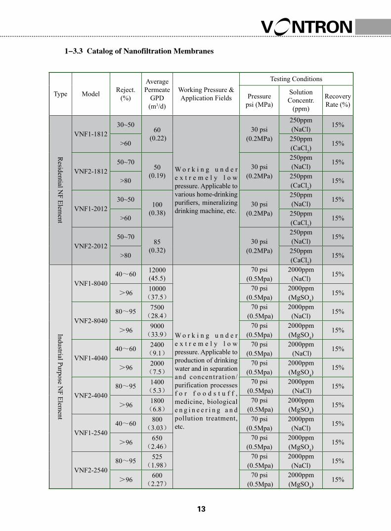
1-3.3 Catalog of Nanofiltration Membranes
Type Model Reject.(%)
Average Permeate
GPD (m3/d)
Working Pressure & Application Fields
Testing Conditions
Pressurepsi (MPa)
Solution Concentr.
(ppm)
Recovery Rate (%)
Residential N
F Element
VNF1-181230~50
60 (0.22)
W o r k i n g u n d e r e x t r e m e l y l o w pressure. Applicable to various home-drinking purifiers, mineralizing drinking machine, etc.
30 psi (0.2MPa)
250ppm (NaCl)
15%
>60250ppm (CaCl2)
15%
VNF2-181250~70
50(0.19)
30 psi (0.2MPa)
250ppm (NaCl)
15%
>80250ppm (CaCl2)
15%
VNF1-201230~50
100 (0.38)
30 psi (0.2MPa)
250ppm (NaCl)
15%
>60250ppm (CaCl2)
15%
VNF2-201250~70
85(0.32)
30 psi (0.2MPa)
250ppm (NaCl)
15%
>80250ppm (CaCl2)
15%
Industrial Purpose NF Elem
ent
VNF1-804040~60 12000
(45.5)
W o r k i n g u n d e r e x t r e m e l y l o w pressure. Applicable to production of drinking water and in separation and concentrat ion/purification processes f o r f o o d s t u f f , medicine, biological e n g i n e e r i n g a n d pollution treatment, etc.
70 psi (0.5Mpa)
2000ppm (NaCl)
15%
>96 10000(37.5)
70 psi (0.5Mpa)
2000ppm (MgSO4)
15%
VNF2-804080~95 7500
(28.4)70 psi
(0.5Mpa)2000ppm
(NaCl)15%
>96 9000(33.9)
70 psi (0.5Mpa)
2000ppm (MgSO4)
15%
VNF1-404040~60 2400
(9.1)70 psi
(0.5Mpa)2000ppm (NaCl)
15%
>96 2000(7.5)
70 psi (0.5Mpa)
2000ppm (MgSO4)
15%
VNF2-404080~95 1400
(5.3)70 psi
(0.5Mpa)2000ppm (NaCl)
15%
>96 1800(6.8)
70 psi (0.5Mpa)
2000ppm (MgSO4)
15%
VNF1-254040~60 800
(3.03)70 psi
(0.5Mpa)2000ppm
(NaCl)15%
>96 650(2.46)
70 psi (0.5Mpa)
2000ppm (MgSO4)
15%
VNF2-254080~95 525
(1.98)70 psi
(0.5Mpa)2000ppm
(NaCl)15%
>96 600(2.27)
70 psi (0.5Mpa)
2000ppm (MgSO4)
15%
��
Manual of Product,Technical Support and Service
1-3.4 Guide to Selection of Membrane Elements
1) Selection of Membrane Elements according to Salinity of Feedwater
2) Frame Diagram of Selection of Membrane Elements
T D S
Water Source
T D S≥5,0 00
Expectancy
U LP XLP LP
Hi Rejec.
FR
Pretreatment
H O R
Traditional Pretreatment
SW
T D S <5,0 0 0
T D S≤1,000
��
1-4 Complete Series of VONTRONTM Dry Membrane Elements
Vontron Technology Co., Ltd. is capable of supplying complete series of dry-type
membrane elements.
Compared with wet-type membrane elements, the dry-type elements have the advantages
of easier transportation and installation as well as longer terms of preservation. Complete series
of membrane elements are available in both dry type and wet type from Vontron technology Co.,
Ltd.
1-4.1 Comparison between Dry-type and Wet-type Membrane Elements
Items of Comparison Dry-type Element Wet-type Element
Preservative Solution Not required
1.0%(W) sodium hydrogen sulfite required as preservative solution, which shall be replaced after 90 days of storage.
Preservative Temperature Not higher than 45℃ 0℃~45℃
Breeding of Microbe Free from breeding of any microbe
Prone to breeding of microbes (in case the preservative solution is not replaced in time)
Transportation, etc.
Easier for transportation thanks to light weight, thus decreasing the delivery costs.
Not easy for transportation owing to heavy weight of preservative solut ion, thus increasing the delivery costs.
1-4.2 Precautions for Use of Dry-type Membrane Elements
● Storage of Dry-type Membrane Elements1. The membrane elements must be stored in cool and dry place, and shall not be exposed
to direct sunlight.
2. The dry-type elements shall be stored in the place with temperature not higher than 45,
below which temperature the elements can be stored for unlimited period.
● General Information of Dry-type Membrane Elements1. The dry-type membrane elements shall be always kept in wet condition once been
moistened.
2. Only after being operated for at least 6 hours can the dry-type membrane elements be
disinfected with formaldehyde.
��
Manual of Product,Technical Support and Service
3. The dry-type membrane elements work under the Operating Limits and Conditions and
design guide identical to the wet-type elements of same specifications.
4. Once a dry-type membrane element is moistened to become a wet-type element, it shall
be disposed of according to the methods of storage, preservation and cleaning indicated in this
Manual corresponding to equivalent wet-type membrane element.
5.The initial adjustment and running of RO system shall be conducted in accordance with
the procedures indicated in “Chapter 4 – Operation and Maintenance of RO System”, and the
filtered water and rejected water produced in the first one hour shall be discarded.
��
Chapter II-General Technical Specifications of VONTRONTM RO Membranes
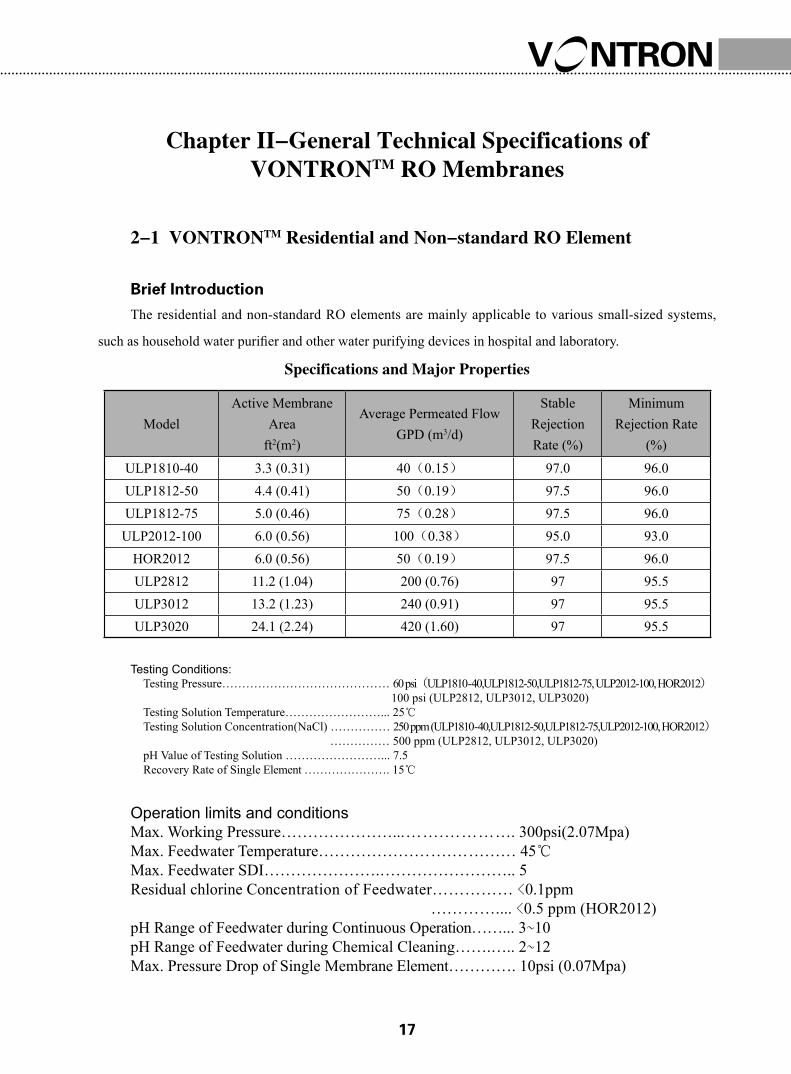
2-1 VONTRONTM Residential and Non-standard RO Element
Brief Introduction
The residential and non-standard RO elements are mainly applicable to various small-sized systems,
such as household water purifier and other water purifying devices in hospital and laboratory.
Specifications and Major Properties
Testing Conditions: Testing Pressure…………………………………… 60 psi(ULP1810-40,ULP1812-50,ULP1812-75, ULP2012-100, HOR2012) 100 psi (ULP2812, ULP3012, ULP3020)Testing Solution Temperature……………………... 25℃Testing Solution Concentration(NaCl) …………… 250 ppm (ULP1810-40,ULP1812-50,ULP1812-75,ULP2012-100, HOR2012) …………… 500 ppm (ULP2812, ULP3012, ULP3020)pH Value of Testing Solution ……………………... 7.5Recovery Rate of Single Element …………………. 15℃
Operation limits and conditionsMax. Working Pressure…………………...…….…………. 300psi(2.07Mpa)Max. Feedwater Temperature…………………….………… 45℃Max. Feedwater SDI………………….…………………….. 5Residual chlorine Concentration of Feedwater…………… <0.1ppm ………….... <0.5 ppm (HOR2012)pH Range of Feedwater during Continuous Operation……... 3~10pH Range of Feedwater during Chemical Cleaning…….….. 2~12Max. Pressure Drop of Single Membrane Element…………. 10psi (0.07Mpa)
Important Information1. Any specific application must be limited within the Operating Limits and Conditions.
We strongly recommend you to refer to the latest edition of technology manual and design
guide prepared by Vontron Technology Co., Ltd., or consult experts proficient in membrane
technology. In case the customer fails to follow the operating conditions as specified in this
manual, Vontron technology Co., Ltd. will assume no liability for all results.
2. The permeate flow listed in the table is the average value. The permeate flow of single
membrane element is within a tolerance not exceeding ±20% of the nominal value.
3. All wet-type membrane elements have been strictly tested before leaving the factory,
and have been treated with the solution of 1.0% sodium hydrogen sulfite (an antifreeze solution
of 10% propanediol required in winter) for storage purpose, then sealed with plastic bag in
vacuum, and further packed in carton boxes. In order to prevent the breeding of microbes during
short-time storage, transportation and system standby, we recommend you to soak the membrane
elements with protective solution (prepared with RO filtered water) containing 1.0% sodium
hydrogen sulfite (foodstuff-purpose).
4. Discard the RO-filtered water produced during the first one hour after system start-up.
5. During storage time and run time, it is strictly prohibited to dose any chemical
medicament that may be harmful to membrane elements. In case of any violation in using
this kind of chemical medicament, Vontron Technology Co., Ltd. assumes no liability for any
outcome incurred herefrom.
Points of Attention1. All data and information provided in this manual have been obtained from long-term
experiment by Vontron Technology Co., Ltd. We truly believe that these data and information
are accurate and effective. Vontron Technology CO., Ltd. assumes no liability for any aftermath
caused by user’s failure in abiding by the conditions specified in this manual in use or
maintenance of membrane products. It is strongly recommended that the user shall strictly abide
by the requirements for design, use and maintenance of products and keep relevant records.
2. Along with technical development and product renovation, the information contained
herein will be subject to modification without prior notification. Please keep an eye on the
website of Vontron Technology Co., Ltd. for any update of product.
�0
Manual of Product,Technical Support and Service
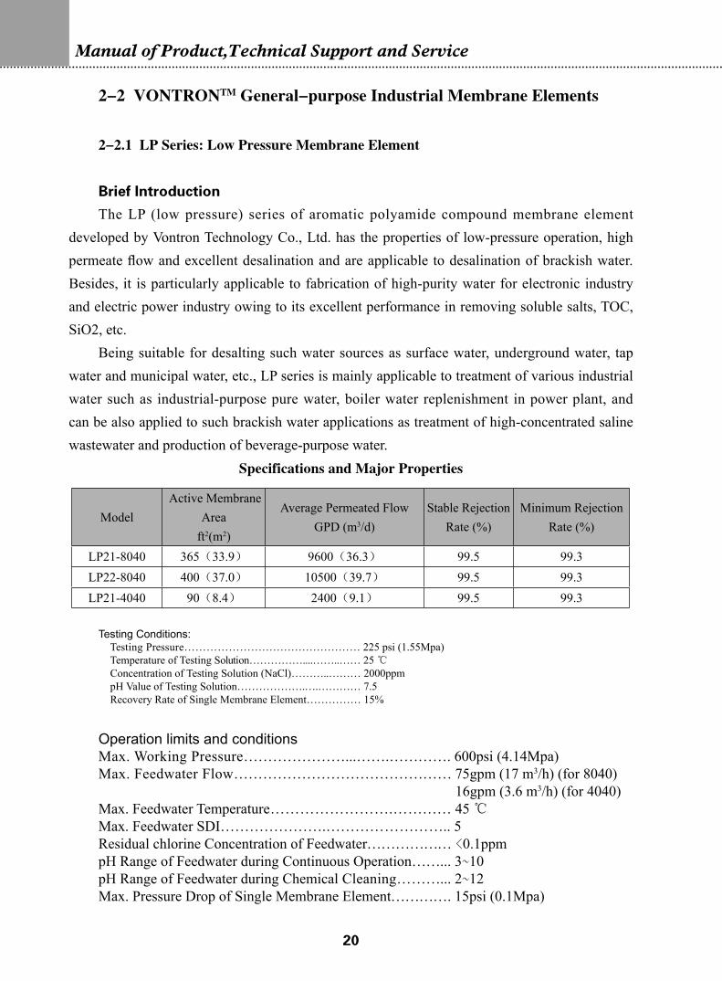
2-2 VONTRONTM General-purpose Industrial Membrane Elements
2-2.1 LP Series: Low Pressure Membrane Element
Brief Introduction
The LP (low pressure) series of aromatic polyamide compound membrane element developed by Vontron Technology Co., Ltd. has the properties of low-pressure operation, high permeate flow and excellent desalination and are applicable to desalination of brackish water. Besides, it is particularly applicable to fabrication of high-purity water for electronic industry and electric power industry owing to its excellent performance in removing soluble salts, TOC, SiO2, etc.
Being suitable for desalting such water sources as surface water, underground water, tap water and municipal water, etc., LP series is mainly applicable to treatment of various industrial water such as industrial-purpose pure water, boiler water replenishment in power plant, and can be also applied to such brackish water applications as treatment of high-concentrated saline wastewater and production of beverage-purpose water.
Specifications and Major Properties
Testing Conditions: Testing Pressure………………………………………… 225 psi (1.55Mpa)Temperature of Testing Solution……………....……..…… 25 ℃Concentration of Testing Solution (NaCl)………..……… 2000ppmpH Value of Testing Solution……………….….………… 7.5Recovery Rate of Single Membrane Element…………… 15%
Operation limits and conditionsMax. Working Pressure…………………...…….…………. 600psi (4.14Mpa)Max. Feedwater Flow……………………………………… 75gpm (17 m3/h) (for 8040) 16gpm (3.6 m3/h) (for 4040)Max. Feedwater Temperature…………………….………… 45 ℃Max. Feedwater SDI………………….…………………….. 5Residual chlorine Concentration of Feedwater……………… <0.1ppmpH Range of Feedwater during Continuous Operation……... 3~10pH Range of Feedwater during Chemical Cleaning………... 2~12Max. Pressure Drop of Single Membrane Element…………. 15psi (0.1Mpa)
Important Information1. Any specific application must be limited within the Operating Limits and Conditions.
We strongly recommend you to refer to the latest edition of technology manual and design
guide prepared by Vontron Technology Co., Ltd., or consult experts proficient in membrane
technology. In case the customer fails to follow the operating conditions as specified in this
manual, Vontron technology Co., Ltd. will assume no liability for all results.
2. The permeate flow listed in the table is the average value. The permeate flow of single
membrane element is within a tolerance not exceeding ±20% of the nominal value.
3. All wet-type membrane elements have been strictly tested before leaving the factory,
and have been treated with the solution of 1.0% sodium hydrogen sulfite (an antifreeze solution
of 10% propanediol required in winter) for storage purpose, then sealed with plastic bag in
vacuum, and further packed in carton boxes. In order to prevent the breeding of microbes during
short-time storage, transportation and system standby, we recommend you to soak the membrane
elements with protective solution (prepared with RO filtered water) containing 1.0% sodium
hydrogen sulfite (foodstuff-purpose).
4. Discard the RO-filtered water produced during the first one hour after system start-up.
5. During storage time and run time, it is strictly prohibited to dose any chemical
��
Manual of Product,Technical Support and Service
medicament that may be harmful to membrane elements. In case of any violation in using
this kind of chemical medicament, Vontron Technology Co., Ltd. assumes no liability for any
outcome incurred herefrom.
Points of Attention1. All data and information provided in this manual have been obtained from long-term
experiment by Vontron Technology Co., Ltd. We truly believe that these data and information
are accurate and effective. Vontron Technology CO., Ltd. assumes no liability for any aftermath
caused by user’s failure in abiding by the conditions specified in this manual in use or
maintenance of membrane products. It is strongly recommended that the user shall strictly abide
by the requirements for design, use and maintenance of products and keep relevant records.
2. Along with technical development and product renovation, the information contained
herein will be subject to modification without prior notification. Please keep an eye on the
website of Vontron Technology Co., Ltd. for any update of product.
2-2.2 ULP Series: Ultra Low Pressure Membrane Element
Brief Introduction
ULP series of ultra-low pressure aromatic polyamide compound membrane element
newly developed by Vontron Technology Co., Ltd. can work under ultra low pressure to reach
as high permeate flow and salt rejection as regular low-pressure membrane element can,
and is applicable to desalination of surface water and underground water. It operates under
approximately 2 thirds of the operating pressure of regular low-pressure composite membrane,
and achieves a salt rejection rate of up to 99.5%, which can decrease the investment costs for
such relevant facilities as pump, piping, and container, etc. and the operating cost for the RO
system, thus increasing the economic efficiency.
Being suitable for the desalting treatment of those water sources with salt concentration
lower than 2000 ppm, such as surface water, underground water, tap water and municipal water,
etc., ULP series membrane elements are mainly applicable to numerous applications of various
scales, such as pure water, boiler water replenishment, foodstuff processing, and pharmaceutical
production, etc.
��
Specifications and Major Properties
Testing Conditions:Testing Pressure………………………………………… 150 psi (1.03Mpa)Temperature of Testing Solution………………………… 25℃Concentration of Testing Solution (NaCl)……………… 1500ppmpH Value of Testing Solution…………………………… 7.5Recovery Rate of Single Membrane Element…………… 15% (8040-size, 4040-size and 2540-size) …………… 8% (4021-size and 2521-size)
Operation limits and conditionsMax. Working Pressure........................................................... 600psi (4.14Mpa)Max. Feedwater Flow.............................................................. 75gpm (17 m3/h) (8040-size) .............................................................. 16gpm (3.6 m3/h) (4040-size)Max. Feedwater Temperature................................................ 45℃Max. Feedwater SDI................................................................ 5Residual chlorine Concentration of Feedwater........................ <0.1ppmpH Range of Feedwater during Continuous Operation............ 3~10pH Range of Feedwater during Chemical Cleaning............... 2~12Max. Pressure Drop of Single Membrane Element.................. 15psi (0.1Mpa)
Important Information1. Any specific application must be limited within the Operating Limits and Conditions.
We strongly recommend you to refer to the latest edition of technology manual and design
guide prepared by Vontron Technology Co., Ltd., or consult experts proficient in membrane
technology. In case the customer fails to follow the operating conditions as specified in this
manual, Vontron technology Co., Ltd. will assume no liability for all results.
2. The permeate flow listed in the table is the average value. The permeate flow of single
membrane element of ULP 31 series and ULP32 series is within a tolerance not exceeding ±
15% of the nominal value, while the single membrane element of other series has a minimum
permeate flow with a tolerance not exceeding 20% of nominal value.
3. All wet-type membrane elements have been strictly tested before leaving the factory,
and have been treated with the solution of 1.0% sodium hydrogen sulfite (an antifreeze solution
of 10% propanediol required in winter) for storage purpose, then sealed with plastic bag in
vacuum, and further packed in carton boxes. In order to prevent the breeding of microbes during
short-time storage, transportation and system standby, we recommend you to soak the membrane
elements with protective solution (prepared with RO filtered water) containing 1.0% sodium
hydrogen sulfite (foodstuff-purpose).
4. Discard the RO-filtered water produced during the first one hour after system start-up.
5. During storage time and run time, it is strictly prohibited to dose any chemical
medicament that may be harmful to membrane elements. In case of any violation in using
this kind of chemical medicament, Vontron Technology Co., Ltd. assumes no liability for any
outcome incurred herefrom.
Points of Attention1. All data and information provided in this manual have been obtained from long-term
experiment by Vontron Technology Co., Ltd. We truly believe that these data and information
are accurate and effective. Vontron Technology CO., Ltd. assumes no liability for any aftermath
caused by user’s failure in abiding by the conditions specified in this manual in use or
maintenance of membrane products. It is strongly recommended that the user shall strictly abide
by the requirements for design, use and maintenance of products and keep relevant records.
2. Along with technical development and product renovation, the information contained
herein will be subject to modification without prior notification. Please keep an eye on the
website of Vontron Technology Co., Ltd. for any update of product.
��
Manual of Product,Technical Support and Service
2-2.3 XLP Series: Extremely Low Pressure Membrane Element
Brief Introduction
XLP series of extremely low pressure aromatic polyamide compound membrane element
newly developed by Vontron Technology Co., Ltd. can work under ultra low pressure to reach
as high permeate flow and salt rejection as regular low-pressure membrane element can,
and is applicable to desalination of surface water and underground water. It operates under
approximately half the operating pressure of regular low-pressure composite membrane, and
achieves a salt rejection rate of up to 99.0%, which can decrease the investment costs for such
relevant facilities as pump, piping, and container, etc. and the operating cost for the RO system,
thus increasing the economic efficiency.
Being suitable for the desalination treatment of those water sources with low salinity not
requiring high salt rejection such as surface water, underground water, tap water and municipal
water, etc. which have a salt concentration lower than 1000 ppm, XLP series of membrane
element is particularly applicable to the second-pass desalination with two-pass RO system, and
is mainly applied to numerous applications of various scales, such as pure water production,
boiler water replenishment, foodstuff processing and pharmaceutical production, etc.
Specifications and Major Properties
Testing Conditions:Testing Pressure…………………………………………100 psi (0.69Mpa)Temperature of Testing Solution………………………… 25℃Concentration of Testing Solution (NaCl)……………… 500ppmpH Value of Testing Solution…………………………… 7.5Recovery Rate of Single Membrane Element…………… 15%
Operation limits and conditionsMax. Working Pressure............................................................ 600psi (4.14Mpa)Max. Feedwater Flow............................................................... 16gpm (3.6 m3/h) Max. Feedwater Temperature................................................... 45℃Max. Feedwater SDI................................................................. 5Residual chlorine Concentration of Feedwater......................... <0.1ppmpH Range of Feedwater during Continuous Operation............ 3~10pH Range of Feedwater during Chemical Cleaning................. 2~12Max. Pressure Drop of Single Membrane Element.................. 15psi (0.1Mpa)
Model Active Membrane
Areaft2(m2)Average Permeated Flow
GPD (m3/d)Stable Rejection
Rate (%)
Minimum Rejection Rate
(%)XLP11-4040 90(8.4) 2000(7.6) 98.0 97.5
��
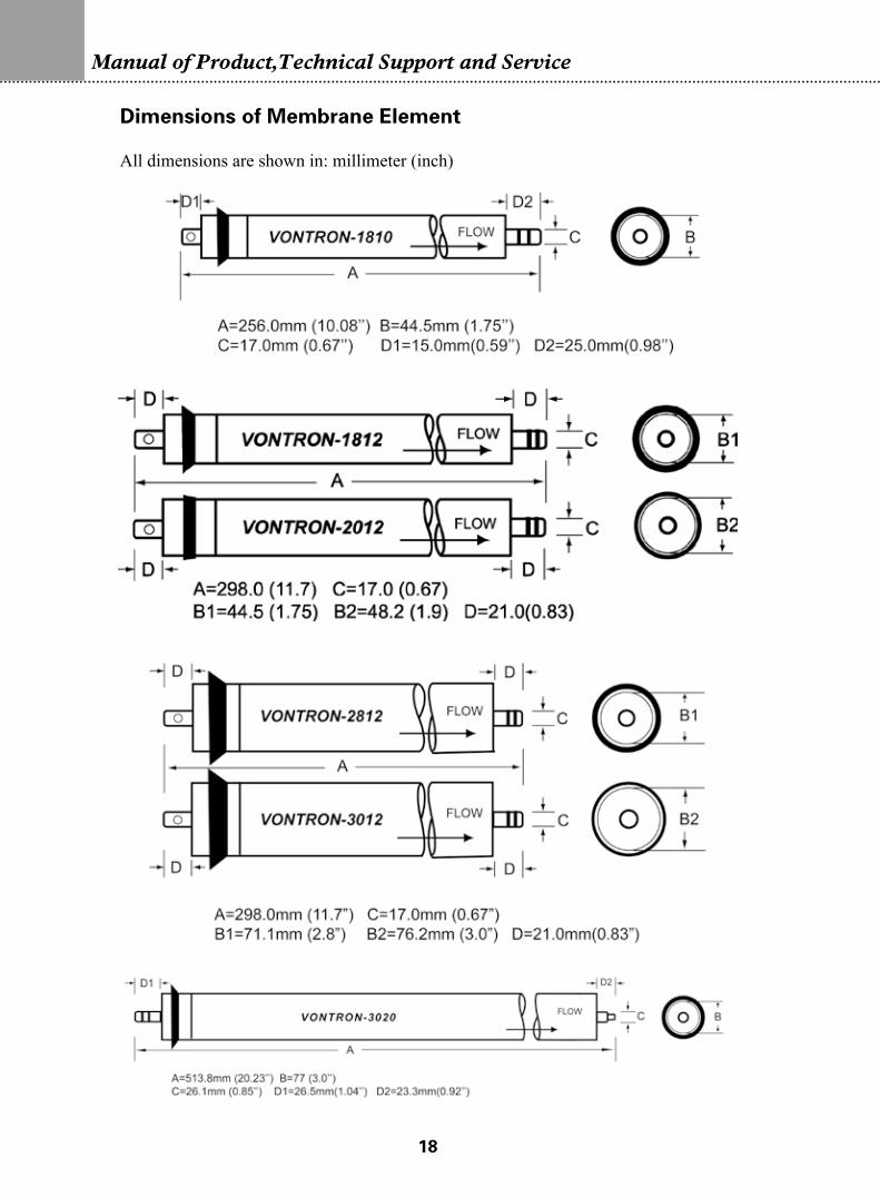
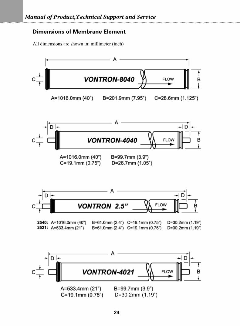
Dimentions of Membrane Element
All dimentions are shown in: millimeter (inch).
Important Information1. Any specific application must be limited within the Operating Limits and Conditions.
We strongly recommend you to refer to the latest edition of technology manual and design
guide prepared by Vontron Technology Co., Ltd., or consult experts proficient in membrane
technology. In case the customer fails to follow the operating conditions as specified in this
manual, Vontron technology Co., Ltd. will assume no liability for all results.
2. The permeate flow listed in the table is the average value. The permeate flow of single
membrane element is within a tolerance not exceeding ±20% of the nominal value.
3. All wet-type membrane elements have been strictly tested before leaving the factory,
and have been treated with the solution of 1.0% sodium hydrogen sulfite (an antifreeze solution
of 10% propanediol required in winter) for storage purpose, then sealed with plastic bag in
vacuum, and further packed in carton boxes. In order to prevent the breeding of microbes during
short-time storage, transportation and system standby, we recommend you to soak the membrane
elements with protective solution (prepared with RO filtered water) containing 1.0% sodium
hydrogen sulfite (foodstuff-purpose).
4. Discard the RO-filtered water produced during the first one hour after system start-up.
5. During storage time and run time, it is strictly prohibited to dose any chemical
medicament that may be harmful to membrane elements. In case of any violation in using
this kind of chemical medicament, Vontron Technology Co., Ltd. assumes no liability for any
outcome incurred herefrom.
Points of Attention1. All data and information provided in this manual have been obtained from long-term
��
Manual of Product,Technical Support and Service
experiment by Vontron Technology Co., Ltd. We truly believe that these data and information are accurate and effective. Vontron Technology CO., Ltd. assumes no liability for any aftermath caused by user’s failure in abiding by the conditions specified in this manual in use or maintenance of membrane products. It is strongly recommended that the user shall strictly abide by the requirements for design, use and maintenance of products and keep relevant records.
2. Along with technical development and product renovation, the information contained herein will be subject to modification without prior notification. Please keep an eye on the website of Vontron Technology Co., Ltd. for any update of product.
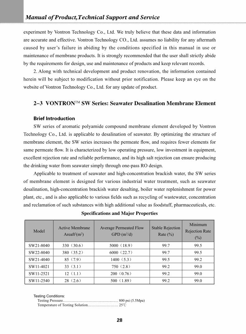
2-3 VONTRONTM SW Series: Seawater Desalination Membrane Element
Brief Introduction
SW series of aromatic polyamide compound membrane element developed by Vontron Technology Co., Ltd. is applicable to desalination of seawater. By optimizing the structure of membrane element, the SW series increases the permeate flow, and requires fewer elements for same permeate flow. It is characterized by low operating pressure, low investment in equipment, excellent rejection rate and reliable performance, and its high salt rejection can ensure producing the drinking water from seawater simply through one-pass RO design.
Applicable to treatment of seawater and high-concentration brackish water, the SW series of membrane element is designed for various industrial water treatment, such as seawater desalination, high-concentration brackish water desalting, boiler water replenishment for power plant, etc., and is also applicable to various fields such as recycling of wastewater, concentration and reclamation of such substances with high additional value as foodstuff, pharmaceuticals, etc.
Specifications and Major Properties
Testing Conditions:Testing Pressure……………………………………… 800 psi (5.5Mpa)Temperature of Testing Solution…………………… 25℃
Concentration of Testing Solution (NaCl)……………… 32800ppmpH Value of Testing Solution…………………………… 7.5Recovery Rate of Single Membrane Element…………… 8% (8040-size, 4040-size and 2540-size) 4% (4021-size and 2521-size)
Operating Limits and ConditionsMax. Working Pressure.......................................................... 1000psi (6.9Mpa)Max. Feedwater Flow............................................................. 75gpm (17 m3/h) (8040-size) 16gpm (3.6 m3/h) (4040 and 4021) 6.0gpm (1.4 m3/h) (2521 and 2540)Max. Feedwater Temperature................................................. 45℃Max. Feedwater SDI............................................................... 5Residual chlorine Concentration of Feedwater....................... <0.1ppmpH Range of Feedwater during Continuous Operation.......... 3~10pH Range of Feedwater during Chemical Cleaning............... 2~12Max. Pressure Drop of Single Membrane Element................ 15psi (0.1Mpa) (8040, 4040 and 2540) 10psi (0.07Mpa) (2521 and 4021)
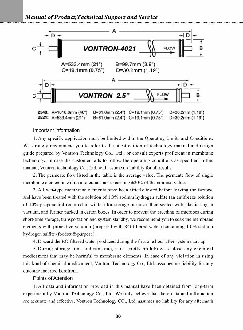
Dimensions of Membrane Element All dimensions are shown in: millimeter (inch)
�0
Manual of Product,Technical Support and Service
Important Information1. Any specific application must be limited within the Operating Limits and Conditions.
We strongly recommend you to refer to the latest edition of technology manual and design guide prepared by Vontron Technology Co., Ltd., or consult experts proficient in membrane technology. In case the customer fails to follow the operating conditions as specified in this manual, Vontron technology Co., Ltd. will assume no liability for all results.
2. The permeate flow listed in the table is the average value. The permeate flow of single membrane element is within a tolerance not exceeding ±20% of the nominal value.
3. All wet-type membrane elements have been strictly tested before leaving the factory, and have been treated with the solution of 1.0% sodium hydrogen sulfite (an antifreeze solution of 10% propanediol required in winter) for storage purpose, then sealed with plastic bag in vacuum, and further packed in carton boxes. In order to prevent the breeding of microbes during short-time storage, transportation and system standby, we recommend you to soak the membrane elements with protective solution (prepared with RO filtered water) containing 1.0% sodium hydrogen sulfite (foodstuff-purpose).
4. Discard the RO-filtered water produced during the first one hour after system start-up.5. During storage time and run time, it is strictly prohibited to dose any chemical
medicament that may be harmful to membrane elements. In case of any violation in using this kind of chemical medicament, Vontron Technology Co., Ltd. assumes no liability for any outcome incurred herefrom.
Points of Attention1. All data and information provided in this manual have been obtained from long-term
experiment by Vontron Technology Co., Ltd. We truly believe that these data and information are accurate and effective. Vontron Technology CO., Ltd. assumes no liability for any aftermath
D=30.2mm (1.19”)
��
caused by user’s failure in abiding by the conditions specified in this manual in use or maintenance of membrane products. It is strongly recommended that the user shall strictly abide by the requirements for design, use and maintenance of products and keep relevant records.
2. Along with technical development and product renovation, the information contained herein will be subject to modification without prior notification. Please keep an eye on the website of Vontron Technology Co., Ltd. for any update of product.
2-4 VONTRONTM FR Series: Fouling Resistant Membrane Element
Brief Introduction
Vontron’s fouling resistant elements include FR series and PURO series.FR (fouling resistant) series of aromatic polyamide RO membrane element developed by
Vontron Technology Co., Ltd. is applicable to desalination of brackish water. It is characterized by low-pressure operation, higher water productivity and excellent desalting performance. Moreover, special treatment has been made to the surface of membrane with unique technology to change its electrical charge and smoothness, increasing the hydrophilicity of membrane surface, thus decreasing the adhesion of contamination and microbe so as to lessen the pollution and extend the service life of elements.
Newly developed by Vontron, the PURO-I is specially designed for treatment of water reclamation and surface water treatment where the water source contains high contamination. This brand-new element contains a new fouling resistant coating, and the membrane surface is treated with special technology to modify the electrical charge and smoothness of membrane surface so as to increasing the hydrophilicity of membrane surface, thus decreasing the adhesion of contamination and microbe so as to lessen the pollution and extend the service life of elements. Besides, the wider 34mil feed spacer channel can provide better fouling resistance and washability.
Vontron’s fouling resistant products are designed for desalting treatment of such water with salt concentration less than 10,000 ppm as surface water, underground water, tap water and municipal water, etc. It is mainly applied to treatment of various industrial water applications, such as reuse of industrial reclaimed water and boiler water replenishment for power plant, etc., and is particularly applicable to treatment of those water containing slight organic pollutants such as industrial wastewater, municipal sewage and other slightly contaminated water.
Specifications and Main Properties
Model Active Membrane
Areaft2(m2)Average Permeated Flow
GPD (m3/d)Stable Rejection
Rate (%)Minimum Rejection
Rate (%)FR11-8040 365(33.9) 9600(36.3) 99.5 99.3
PURO-I 400(37.0) 10500(39.7) 99.5 99.3
FR11-4040 90(8.4) 2200(8.3) 99.5 99.3
��
Manual of Product,Technical Support and Service
Testing Conditions:Testing Pressure………………………………………… 225 psi (1.55Mpa)Temperature of Testing Solution………………………… 25℃Concentration of Testing Solution (NaCl)……………… 2000ppmpH Value of Testing Solution…………………………… 7.5Recovery Rate of Single Membrane Element…………… 15%
Operating Limits and ConditionsMax. Working Pressure............................................................ 600psi (4.14Mpa)Max. Feedwater Flow.............................................................. 75gpm (17 m3/h) (8040-size) 16gpm (3.6 m3/h) (4040-size)Max. Feedwater Temperature................................................... 45℃Max. Feedwater SDI................................................................ 5Residual chlorine Concentration of Feedwater........................ <0.1ppmpH Range of Feedwater during Continuous Operation............ 3~10pH Range of Feedwater during Chemical Cleaning................. 2~12Max. Pressure Drop of Single Membrane Element.................. 15psi (0.1Mpa)
Dimensions of Membrane Element
All dimensions are shown in: millimeter (inch)
��
Important Information1. Any specific application must be limited within the Operating Limits and Conditions.
We strongly recommend you to refer to the latest edition of technology manual and design guide prepared by Vontron Technology Co., Ltd., or consult experts proficient in membrane technology. In case the customer fails to follow the operating conditions as specified in this manual, Vontron technology Co., Ltd. will assume no liability for all results.
2. The permeate flow listed in the table is the average value. The permeate flow of single membrane element is within a tolerance not exceeding ±15% of the nominal value.
3. All wet-type membrane elements have been strictly tested before leaving the factory, and have been treated with the solution of 1.0% sodium hydrogen sulfite (an antifreeze solution of 10% propanediol required in winter) for storage purpose, then sealed with plastic bag in vacuum, and further packed in carton boxes. In order to prevent the breeding of microbes during short-time storage, transportation and system standby, we recommend you to soak the membrane elements with protective solution (prepared with RO filtered water) containing 1.0% sodium hydrogen sulfite (foodstuff-purpose).
4. Discard the RO-filtered water produced during the first one hour after system start-up.5. During storage time and run time, it is strictly prohibited to dose any chemical
medicament that may be harmful to membrane elements. In case of any violation in using this kind of chemical medicament, Vontron Technology Co., Ltd. assumes no liability for any outcome incurred herefrom.
Points of Attention1. All data and information provided in this manual have been obtained from long-term
experiment by Vontron Technology Co., Ltd. We truly believe that these data and information are accurate and effective. Vontron Technology CO., Ltd. assumes no liability for any aftermath caused by user’s failure in abiding by the conditions specified in this manual in use or maintenance of membrane products. It is strongly recommended that the user shall strictly abide by the requirements for design, use and maintenance of products and keep relevant records.
2. Along with technical development and product renovation, the information contained herein will be subject to modification without prior notification. Please keep an eye on the website of Vontron Technology Co., Ltd. for any update of product.
2-5 VONTRONTM HOR Series: High Oxidation Resistant Membrane Element
Brief Introduction
HOR (high oxidation resistant) series of aromatic polyamide compound membrane element newly developed by Vontron Technology Co., Ltd. has the properties of low operating
��
Manual of Product,Technical Support and Service
pressure, high permeate flow and excellent rejection performance, etc. Besides, the use of special synthesizing process enhances the oxidation property of membrane element and enables the membrane element to endure the impact by certain magnitude of oxidative substance, thus simplifying and optimizing the pretreatment process of RO system, decreasing the microbial contamination of membrane element, saving the operating cost and elongating the service life.
Industrial HOR series is designed for the desalting treatment of those water sources with salinity lower than 10000ppm such as surface water, underground water, tap water and municipal water, etc., and is especially applicable to reuse treatment of those water sources that contain microbial contamination or oxidative substance, such as municipal-purpose or industrial-purpose reclaimed water, electroplating wastewater, etc. The residential HOR-2012 element is mainly applied to various miniature systems such as household water purifier, water purifying devices for hospital and laboratory, etc.
Testing Conditions:Testing Pressure………………………………………… 225 psi (1.55Mpa) Temperature of Testing Solution………………………… 25 ℃ Concentration of Testing Solution (NaCl)……………… 2000ppmpH Value of Testing Solution…………………………… 7.5Recovery Rate of Single Membrane Element…………… 15%
Operating Limits and ConditionsMax. Working Pressure............................................................ 600psi (4.14Mpa) (for 8040 and 4040)Max. Feedwater Flow............................................................... 75gpm (17 m3/h) (for 8040) 16gpm (3.6 m3/h) (for 4040)Max. Feedwater Temperature................................................... 45℃Max. Feedwater SDI................................................................ 5Residual chlorine Concentration of Feedwater........................ <0.5ppmpH Range of Feedwater during Continuous Operation............ 3~10pH Range of Feedwater during Chemical Cleaning................. 2~12Max. Pressure Drop of Single Membrane Element.................. 15psi (0.1Mpa) (for 8040 and 4040)
��
Dimensions of Membrane Element
All dimensions are shown in: millimeter (inch)
Important Information1. When hypochlorite is dosed, the catalytic and oxidative metallic ions in the feedwater,
such as Cu2+, Ni2+, etc. shall be completely removed.
2. When hypochlorite is dosed, the pH value and temperature of Feedwater shall be kept
under careful control to make sure that the feedwater temperature doesn’t exceed 30℃ and the
pH value is preferably between 6~8. Higher feedwater temperature or improper pH value may
quicken the oxidation.
3. The salt permeation rate shall not exceed 4 times of the initial value within 3 years of
service life.
4. It would be best to use the feedwater pipe made of high-pressure PVC or stainless with
high resistance to corrosion, the membrane housing made of FRP, the pump and instrument
made of FRP with high resistance to corrosion and containing no bronze component.
5. Since there is residual chlorine in the side of permeated water, the customer shall
choose to carry out dechlorination treatment as per the practical application. Post carbon is
recommended for this purpose.
6. When it is required to carry out impact disinfection, the hypochlorite solution with 2ppm
concentration can be selected.
��
Manual of Product,Technical Support and Service
7. Any specific application must be limited within the Operating Limits and Conditions.
We strongly recommend you to refer to the latest edition of technology manual and design
guide prepared by Vontron Technology Co., Ltd., or consult experts proficient in membrane
technology. In case the customer fails to follow the operating conditions as specified in this
manual, Vontron technology Co., Ltd. will assume no liability for all results.
8. The permeate flow listed in the table is the average value. The permeate flow of single
membrane element is within a tolerance not exceeding ±20% of the nominal value.
9. All wet-type membrane elements have been strictly tested before leaving the factory,
and have been treated with the solution of 1.0% sodium hydrogen sulfite (an antifreeze solution
of 10% propanediol required in winter) for storage purpose, then sealed with plastic bag in
vacuum, and further packed in carton boxes. In order to prevent the breeding of microbes during
short-time storage, transportation and system standby, we recommend you to soak the membrane
elements with protective solution (prepared with RO filtered water) containing 1.0% sodium
hydrogen sulfite (foodstuff-purpose).
10. Discard the RO-filtered water produced during the first one hour after system start-up.
11. During storage time and run time, it is strictly prohibited to dose any chemical
medicament that may be harmful to membrane elements. In case of any violation in using
this kind of chemical medicament, Vontron Technology Co., Ltd. assumes no liability for any
outcome incurred herefrom.
Points of Attention1. All data and information provided in this manual have been obtained from long-term
experiment by Vontron Technology Co., Ltd. We truly believe that these data and information
are accurate and effective. Vontron Technology CO., Ltd. assumes no liability for any aftermath
caused by user’s failure in abiding by the conditions specified in this manual in use or
maintenance of membrane products. It is strongly recommended that the user shall strictly abide
by the requirements for design, use and maintenance of products and keep relevant records
2. Along with technical development and product renovation, the information contained
herein will be subject to modification without prior notification. Please keep an eye on the
website of Vontron Technology Co., Ltd. for any update of product.
��
Chapter III- General Technical Specifications of VONTRONTM NF Membranes
3.1 Nanofiltration Membranes–Residential Element
Brief IntroductionApplicable to various small-sized drinking systems, such as home drinking water purifiers,
mineralized drinking fountain, etc., the residential 1812-type and 2012-type NF elements are designed for removing from water various organics, microbes, viruses and most metallic ions with two or higher valence while retaining part of the sodium, potassium, calcium and magnesium ions, etc., thus improving the mouthfeel of purified water and maintaining the content of mineral nutrition.
VNF1: Moderate rejection rate; Moderate passage of calciumVNF2: Higher rejection of calcium
Specifications and Major Properties
Testing ConditionsTesting Pressure………………………………… 30 psi (0.2Mpa)Temperature of Testing Solution……………… 25 ℃Concentration of Solution (NaCl)……………… 250ppmConcentration of Solution (CaCl2)……………… 250ppmpH Value of Solution…………………………… 7.5Single Element Recovery……………………… 15%
Operating Limits and ConditionsMax Working Pressure..................................................... 300psi(2.07Mpa)Max Feedwater Temperature........................................... 45℃Max Feedwater SDI......................................................... 5Max Feedwater Hardness................................................. 400 ppmFree Chlorine Concentration of Feedwater...................... <0.1ppmpH range of feedwater during cont. oper........................ 3~10pH range of feedwater during chem. cleaning................. 2~12Max Pressure Drop of Single Element............................ 10 psi(0.07Mpa)
Model [Active Membrane Area] ft2(m2) Solution Type [Average Permeate]
GPD(m3/d) [Stable Rejection] %
VNF1-1812 4.4 (0.41)NaCl
60 (0.22)30~50
CaCl2 >60
VNF2-1812 4.4 (0.41)NaCl
50 (0.19)50~70
CaCl2 >80
VNF1-2012 5.0 (0.46)NaCl
100 (0.38)30~50
CaCl2 >60
VNF2-2012 5.0 (0.46)NaCl
85 (0.32)50~70
CaCl2 >80
Notes: The permeate flow of single membrane element may vary within (-15%) ~ (25%)
��
Manual of Product,Technical Support and Service
Dimensions
All dimensions are shown in millimeter (inch)
Important Information1. Any specific application must be limited within the Operating Limits and Conditions.
We strongly recommend you to refer to the latest edition of technology manual and design
guide prepared by Vontron Technology Co., Ltd., or consult experts proficient in membrane
technology. In case the customer fails to follow the operating conditions as specified in this
manual, Vontron technology Co., Ltd. will assume no liability for any result.
2. The permeate flow listed in the table is the average value. The permeate flow of single
membrane element is within a tolerance not exceeding ±25% of the nominal value.
3. The wet-type membrane elements have been strictly tested before leaving the factory,
and have been treated with the solution of 1.0% sodium hydrogen sulfite (an antifreeze solution
of 10% propanediol required in winter) for storage purpose, then sealed with plastic bag in
vacuum, and further packed in carton boxes. In order to prevent the breeding of microbes during
short-time storage, transportation and system standby, we recommend you to soak the membrane
elements with protective solution (prepared with RO filtered water) containing 1.0% sodium
hydrogen sulfite (foodstuff-purpose).
4. Discard the RO-filtered water produced during the first one hour after system start-up.
5. During storage time and run time, it is strictly prohibited to dose any chemical
medicament that may be harmful to membrane elements. In case of any violation in using
this kind of chemical medicament, Vontron Technology Co., Ltd. assumes no liability for any
outcome incurred herefrom.
��
Points of Attention1. All data and information provided in this manual have been obtained from long-term
experiment by Vontron Technology Co., Ltd. We truly believe that these data and information
are accurate and effective. Vontron Technology CO., Ltd. assumes no liability for any aftermath
caused by user’s failure in abiding by the conditions specified in this manual in use or
maintenance of membrane products. It is strongly recommended that the user shall strictly abide
by the requirements for design, use and maintenance of products and keep relevant records.
2. Along with technical development and product renovation, the information contained
herein will be subject to modification without prior notification. Please visit the website of
Vontron Technology Co., Ltd. for any update of product.
3.2 Nanofiltration Membranes-Industrial Element
Brief Introduction
The industrial nanofiltration element is designed for removing from water various organics,
microbes, viruses and most metallic ions with two or higher valence while retaining part of the
sodium, potassium, calcium and magnesium ions, etc. Nanofiltration, free of chemical reaction,
heating and transformation, can keep the biological activity undamaged and maintain the
primary flavor or fragrance of substance unchanged, and is increasingly applied in production
of drinking water and in separation and concentration/purification processes for foodstuff,
medicine, biological engineering and pollution treatment, etc.
VNF1: Moderate rejection rate; Moderate passage of calcium; High removal of TOC
VNF2: Higher rejection rate; Satisfactory removal of insecticide, herbicide, TOC and transition metals.
�0
Manual of Product,Technical Support and Service
Specifications and Major Properties
Testing ConditionsTesting Pressure………………………………… 70 psi (0.5Mpa)Temperature of Testing Solution……………… 25 ℃Concentration of Solution (NaCl)……………… 2000ppmConcentration of Solution (MgSO4)…………… 2000ppmpH Value of Solution…………………………… 7.5Single Element Recovery……………………… 15%
Operating Limits and ConditionsMax Working Pressure................................................ 600psi(4.14Mpa)Max Feedwater Flow................................................... 75gpm(17 m3/h) (8040) ................................................... 16gp(3.6 m3/h) (4040)Max Feedwater Temperature...................................... 45℃Max Feedwater SDI.................................................... 5Free Chlorine Concentration of Feedwater................. <0.1ppmpH range of feedwater during cont. oper.................... 3~10pH range of feedwater during chem. cleaning............ 2~12Max Pressure Drop of Single Element........................ 15 psi(0.1Mpa)
Model [Active Membrane Area] ft2(m2) Solution Type [Average Permeate]
GPD(m3/d)[Stable Rejection]
%
VNF1-8040 400(37.2)NaCl 12000(45.5) 40~60
MgSO4 10000(37.5) >96
VNF2-8040 400(37.2)NaCl 7500(28.4) 80~95
MgSO4 9000(33.9) >96
VNF1-4040 80(7.4)NaCl 2400(9.1) 40~60
MgSO4 2000(7.5) >96
VNF2-4040 80(7.4)NaCl 1400(5.3) 80~95
MgSO4 1800(6.8) >96
VNF1-2540 28(2.6)NaCl 800(3.03) 40~60
MgSO4 650(2.46) >96
VNF2-2540 28(2.6)NaCl 525(1.98) 80~95
MgSO4 600(2.27) >96
Notes: Minimum rejection of MgSO4 is 94%. The permeate flow of single element may vary within ±25%.
��
Dimensions of Membrane Element
All dimensions are shown in: millimeter (inch)
Important Information1. Any specific application must be limited within the extreme operating conditions.
We strongly recommend you to refer to the latest edition of technology manual and design
guide prepared by Vontron Technology Co., Ltd., or consult experts proficient in membrane
technology. In case the customer fails to follow the operating conditions as specified in this
manual, Vontron technology Co., Ltd. will assume no liability for any result.
2. The permeate flow listed in the table is the average value. The permeate flow of single
membrane element is within a tolerance not exceeding ±25% of the nominal value
3. The wet-type membrane elements have been strictly tested before leaving the factory,
and have been treated with the solution of 1.0% sodium hydrogen sulfite (an antifreeze solution
of 10% propanediol required in winter) for storage purpose, then sealed with plastic bag in
��
Manual of Product,Technical Support and Service
vacuum, and further packed in carton boxes. In order to prevent the breeding of microbes during
short-time storage, transportation and system standby, we recommend you to soak the membrane
elements with protective solution (prepared with RO filtered water) containing 1.0% sodium
hydrogen sulfite (foodstuff-purpose).
4. Discard the RO-filtered water produced during the first one hour after system start-up.
5. During storage time and run time, it is strictly prohibited to dose any chemical
medicament that may be harmful to membrane elements. In case of any violation in using
this kind of chemical medicament, Vontron Technology Co., Ltd. assumes no liability for any
outcome incurred herefrom.
Points of Attention1. All data and information provided in this manual have been obtained from long-term
experiment by Vontron Technology Co., Ltd. We truly believe that these data and information
are accurate and effective. Vontron Technology CO., Ltd. assumes no liability for any aftermath
caused by user’s failure in abiding by the conditions specified in this manual in use or
maintenance of membrane products. It is strongly recommended that the user shall strictly abide
by the requirements for design, use and maintenance of products and keep relevant records.
2. Along with technical development and product renovation, the information contained
herein will be subject to modification without prior notification. Please visit the website of
Vontron Technology Co., Ltd. for any update of product.
��
Chapter IV-Guide to Design of RO System
A complete set of RO system consists of 4 parts: pretreatment; RO section (membrane
filtration); post-treatment; system cleaning section. An RO is reasonably designed according to
specific feedwater quality and various requirements for product water quality so as to decrease
the contamination speed, elongate the cleaning cycle of system, reduce the cleaning frequency,
improve the long-term stability of system and decrease the operating costs of system.
The system is designed generally according to the following steps:
1) Completely analyzing the quality of water source
2) Designing a reasonable and efficient pretreatment solution in line with the water sources.
3) Designing a reasonable RO system in accordance with permeate flow and product water
quality, etc.
4) Designing the post-treatment section (such as mixed bed or EDI system) to produce the
water with higher quality.
5) Designing a reasonable system of chemical cleaning.
6) Determining the designing parameters for pilot test of large-sized system.
4-1 Design of Pretreatment Section of RO System
4-1.1 Analysis of Type and Quality of Raw Water
4-1.1.1 Type of Raw WaterThe type of water is determined by the total dissolved solids (TDS) and the organic content
of the raw water:
① RO filtered water, with TDS generally less than 50 mg/L.
② Tap water, with TDS generally less than 500 mg/L
③ Brackish water, with TDS generally lower than 5000mg/L, classified as surface water and underground water.
④ Quasi seawater, with TDS generally between 5,000~15,000 mg/L.
⑤ Seawater, with TDS generally at 35,000 mg/L
⑥ Grade-III wastewater (reclaimed water), with organic substance at comparatively high content (high values of TOC and BOD).
Different types of water source require different processes of pretreatment and different
��
Manual of Product,Technical Support and Service
models of membrane element. For designing small-sized engineering projects without the
conditions for water quality analysis or test, please refer to the pretreatment system of those
projects that have been put into operation for similar water sources. Nevertheless, full analysis
of water quality must be done for large-scale engineering project.
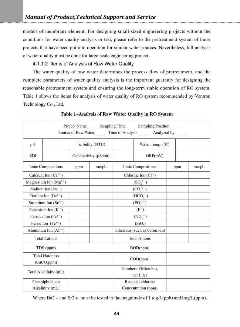
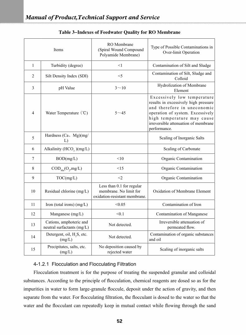
4-1.1.2 Items of Analysis of Raw Water QualityThe water quality of raw water determines the process flow of pretreatment, and the
complete parameters of water quality analysis is the important guaranty for designing the
reasonable pretreatment system and ensuring the long-term stable operation of RO system.
Table 1 shows the items for analysis of water quality of RO system recommended by Vontron
Technology Co., Ltd.
Table 1-Analysis of Raw Water Quality in RO System
Project Name Sampling Time Sampling Position Source of Raw Water Time of Analysis Analyzed by
Calcium Ion (Ca2+) Chlorine Ion (Cl-)Magnesium Ion (Mg2+) (SO4
2-)Sodium Ion (Na+) (CO3
2-)Barium Ion (Ba2+) (HCO3
-)Strontium Ion (Sr2+) (PO4
3-)Potassium Ion (K+) (F-)Ferrous Ion (Fe2+) (NO3
-)Ferric Ion (Fe3+) (SiO2)
Aluminum Ion (Al3+) OtherIons (such as boron ion)
Total Cations Total Anions
TDS (ppm) BOD(ppm)
Total Hardness (CaCO3ppm)
COD(ppm)
Total Alkalinity (mL)Number of Microbes,
per Liter Phenolphthalein Alkalinity (mL)
Residual chlorine Concentration (ppm)
Where Ba2+and Sr2+ must be tested to the magnitude of 1μg/L(ppb) and1mg/L(ppm).
��
4-1.1.3 Descriptions of Each Item of Water Quality Analysis and Its Significance
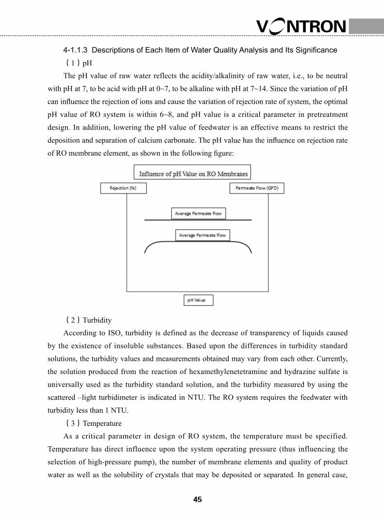
(1)pHThe pH value of raw water reflects the acidity/alkalinity of raw water, i.e., to be neutral
with pH at 7, to be acid with pH at 0~7, to be alkaline with pH at 7~14. Since the variation of pH
can influence the rejection of ions and cause the variation of rejection rate of system, the optimal
pH value of RO system is within 6~8, and pH value is a critical parameter in pretreatment
design. In addition, lowering the pH value of feedwater is an effective means to restrict the
deposition and separation of calcium carbonate. The pH value has the influence on rejection rate
of RO membrane element, as shown in the following figure:
(2)TurbidityAccording to ISO, turbidity is defined as the decrease of transparency of liquids caused
by the existence of insoluble substances. Based upon the differences in turbidity standard
solutions, the turbidity values and measurements obtained may vary from each other. Currently,
the solution produced from the reaction of hexamethylenetetramine and hydrazine sulfate is
universally used as the turbidity standard solution, and the turbidity measured by using the
scattered –light turbidimeter is indicated in NTU. The RO system requires the feedwater with
turbidity less than 1 NTU.
(3)TemperatureAs a critical parameter in design of RO system, the temperature must be specified.
Temperature has direct influence upon the system operating pressure (thus influencing the
selection of high-pressure pump), the number of membrane elements and quality of product
water as well as the solubility of crystals that may be deposited or separated. In general case,
��
Manual of Product,Technical Support and Service
each temperature drop by 3℃ will cause a 10% decrease of RO system yield; each temperature
drop by 5℃ will require a 15% increase of water pump pressure. If the temperature rises, the
salt permeation of RO system increases and the conductivity of product water also rises. If the
temperature drops, the salt permeation of RO system decreases and the conductivity of product
water decreases.
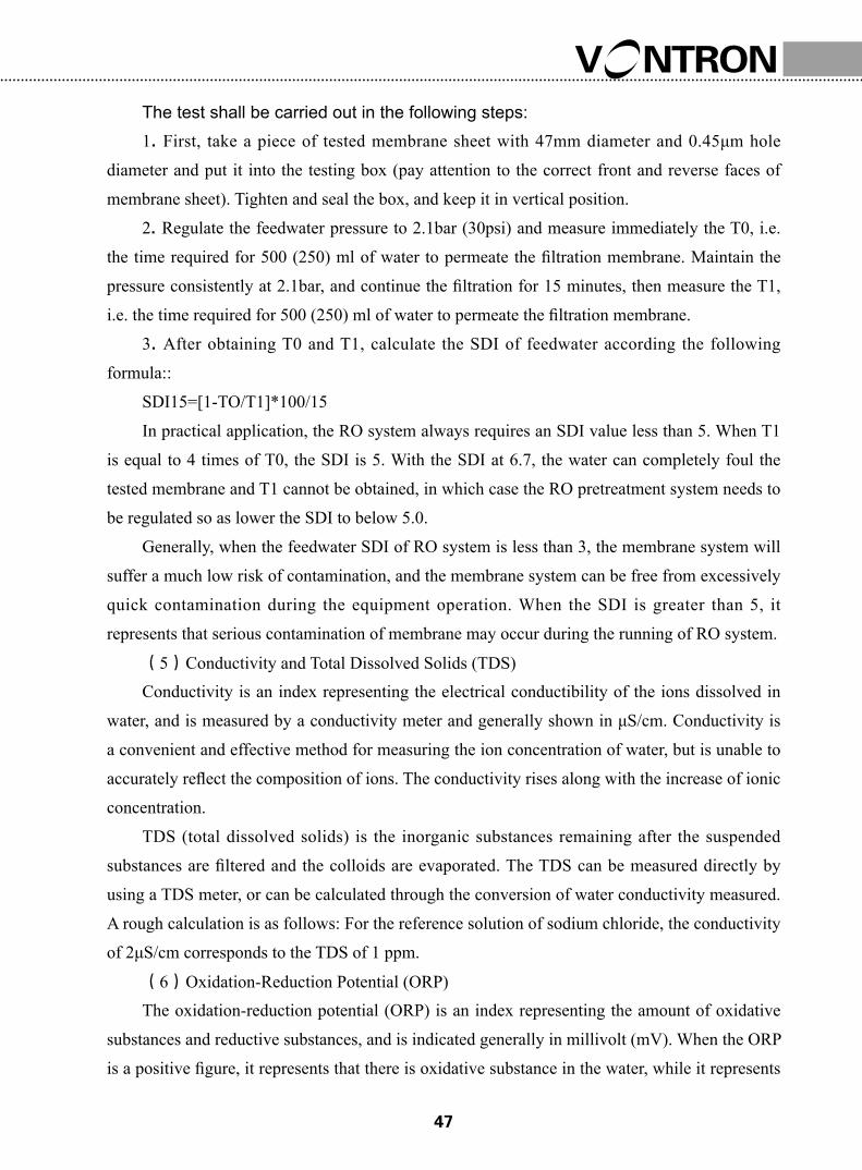
(4)SDISDI (Silt Density Index), also known as fouling index (FI), is an important index
representing the feedwater quality of RO system, and is the best way for determining the
colloidal and granular contamination in the feedwater of RO system. The standard method for
inspecting the SDI is specified in ASTM TEST (D189-82).
Above is the diagram of an SDI Tester.
��
The test shall be carried out in the following steps:1. First, take a piece of tested membrane sheet with 47mm diameter and 0.45μm hole
diameter and put it into the testing box (pay attention to the correct front and reverse faces of
membrane sheet). Tighten and seal the box, and keep it in vertical position.
2. Regulate the feedwater pressure to 2.1bar (30psi) and measure immediately the T0, i.e.
the time required for 500 (250) ml of water to permeate the filtration membrane. Maintain the
pressure consistently at 2.1bar, and continue the filtration for 15 minutes, then measure the T1,
i.e. the time required for 500 (250) ml of water to permeate the filtration membrane.
3. After obtaining T0 and T1, calculate the SDI of feedwater according the following
formula::
SDI15=[1-TO/T1]*100/15
In practical application, the RO system always requires an SDI value less than 5. When T1
is equal to 4 times of T0, the SDI is 5. With the SDI at 6.7, the water can completely foul the
tested membrane and T1 cannot be obtained, in which case the RO pretreatment system needs to
be regulated so as lower the SDI to below 5.0.
Generally, when the feedwater SDI of RO system is less than 3, the membrane system will
suffer a much low risk of contamination, and the membrane system can be free from excessively
quick contamination during the equipment operation. When the SDI is greater than 5, it
represents that serious contamination of membrane may occur during the running of RO system.
(5)Conductivity and Total Dissolved Solids (TDS)Conductivity is an index representing the electrical conductibility of the ions dissolved in
water, and is measured by a conductivity meter and generally shown in μS/cm. Conductivity is
a convenient and effective method for measuring the ion concentration of water, but is unable to
accurately reflect the composition of ions. The conductivity rises along with the increase of ionic
concentration.
TDS (total dissolved solids) is the inorganic substances remaining after the suspended
substances are filtered and the colloids are evaporated. The TDS can be measured directly by
using a TDS meter, or can be calculated through the conversion of water conductivity measured.
A rough calculation is as follows: For the reference solution of sodium chloride, the conductivity
of 2μS/cm corresponds to the TDS of 1 ppm.
(6)Oxidation-Reduction Potential (ORP)The oxidation-reduction potential (ORP) is an index representing the amount of oxidative
substances and reductive substances, and is indicated generally in millivolt (mV). When the ORP
is a positive figure, it represents that there is oxidative substance in the water, while it represents
��
Manual of Product,Technical Support and Service
that there is reductive substance in water when the ORP is a negative figure. In general, the RO
system requires the ORP of feedwater to be less than 200 mV.
The oxidative substances in water generally include residual chlorine, ozone, etc. Since
compound polyamide membrane has an inferior resistance to oxidation, VONTRON membrane
series require the residual chlorine content of feedwater not to exceed 0.1 ppm. For the water
sources with high ORP, the oxidative substances must be removed by using the activated carbon
adsorption or dosing the reductant.
Sometimes the water in the nature may appear to be negative in ORP, which means that
there is H2S, SO32-, or Fe2+, etc. in the water. The RO system is also sensitive to H2S and Fe2+, because
tthese two substances may cause colloidal and microbic contamination. A number of methods,
such as activated carbon adsorption, oxidative deposition, flocculation filtration, ionic exchange,
etc., can be adopted to get rid of these substances in pretreatment system.
(7)Composition of IonsOf the inorganic salts dissolved in water, the hardly or slightly soluble salts formed from
the combination of cations and anions may become some soluble at certain temperature, and may
foul on the surface of RO membrane when the Feedwater of RO system has been continuously
concentrated to exceed the solubility limit. The hardly soluble salts frequently seen include
CaCO3 and CaSO4, and other compounds that may result in scaling include CaF2, BaSO4, SrSO4
and Ca3(PO4)2. In case it’s possible that the cations and anions form the hardly or slightly soluble
salts as mentioned above, measures must be taken to control the fouling in pretreatment and to
avoid deposition or fouling caused by the situation that the concentration of hardly or slightly
soluble salts exceed their solubility. Vontron’s RODesign or other design software can be utilized
to determine whether the hardly or slightly soluble salts can deposit under the designed recovery
conditions.
(8)HardnessHardness of water means the concentration of calcium and magnesium ions in the water,
measured in mg/L as CaCO3. For the water sources with high hardness and alkalinity, special
importance should be attached to the prevention of CaCO3 scaling in pretreatment process.
��
HardnessMeq/L mg/L as CaCO3
soft <1 <50moderately hard 1~3 50~150hard 3~6 150~300very hard >6 >300
(9)AlkalinityAlkalinity refers to the content of alkaline substances that can react with strong acid
(generally the standard HCL solution with 0.1mol/L concentration) in the water. Alkalinity is
mainly for representing the content of bicarbonate (HCO3-), carbonate (CO3
2-) and hydroxide
ions, and is classified into phenolphthalein alkalinity and total alkalinity. When in titration, the
alkalinity measured by using phenolphthalein as indicator (pH = 8.3 at the end point indicated)
is called “phenolphthalein alkalinity”. The alkalinity measured by using orange methyl orange
as indicator (pH = 4.4~4.5 at the end point indicated) is called “methyl-orange alkalinity” or
“total alkalinity”. Therefore, phenolphthalein alkalinity is simply part of the total alkalinity.
The relationship between “phenolphthalein alkalinity” and “total alkalinity” is shown in the
following table:
Table 2-Relationship between Alkalinity and Part of the Ions Contained in Water
Relation between M and PContent of Various Alkalinities of Water
HCO3- CO3
2- OH-
M=0,
namely A=P0 0 A
A>2P,
Namely M>PM-P 2P 0
A<2P,
Namely M<P0 2M P-M
A=2P,
Namely M=P0 A 0
P=0,
Namely A=M A=M 0 0
Notes1. The concentration of standard solution HC1 is 0.1 mol/L.2. P is the volume of standard solution consumed where phenolphthalein is used as the indicator; M is the volume of standard solution consumed where methyl orange is used as the indicator subsequently after titration is conducted with phenolphthalein as the indicator.3. A = M + P, i.e. the total consumption of standard solution.
�0
Manual of Product,Technical Support and Service
(10)COD、BOD、TOCIn water treatment, three indexes, i.e. chemical oxygen demand (COD), biochemical
oxygen demand (BOD) and total organic carbon (TOC) are generally used for representing the
content of organic substances in water. There are great varieties of organic substances in the
nature, and the organic constituents contained in water mainly consists of humic acid, surfactant,
oil, microbes, agricultural chemicals, etc.
1)Chemical oxygen demand (COD) refers to the consumption of oxidant when
strong oxidant is used for treating the sampled water under certain conditions. It is an index
representing the amount of reductive substances contained in water. Though also containing
nitrite, sulphide and ferrous salt, etc., the reductive substances in water consist mainly of
organic substances. Therefore, the chemical oxygen demand (COD) is usually used as an index
representing the amount of organic substances in water. There are two reagents for determining
the COD, i.e. potassium bichromate (CODCr) and acid potassium permanganate (CODMn), of
which the former is mostly applied to the test of industrial waste water and the latter is applied to
the test of natural water. Since potassium bichromate has a stronger oxidizability than potassium
permanganate, the CODCr is generally greater than CODMn.
Biochemical oxygen demand (BOD) is the total amount of oxygen dissolved in water
consumed for the inorganic transformation and gasification of organic substances owing to
oxidation and decomposition caused by the biochemical action of microbes. It is indicated in
ppm (mg/L). Currently in both domestic and abroad, the amount of oxygen consumed in five
days of breeding at temperature of 20℃ is used as the index of BOD, called BOD5.
The biochemical property, i.e. the ratio of BOD5 to CODCr, represents the content
of organic matters contained in the water that can be biologically decomposed. The higher
the ratio is, the better the biochemical capability is, and the lower is the content of organic
substances contained in the water produced from biochemical treatment, or vice versa with
the lower ratio.
2) Total Organic Carbon (TOC): It is a comprehensive index indicating the total organic
matters contained in water body by means of carbon content. The firing method is used for
measuring the TOC, which can completely oxidize the organic matters. It can represent the total
amount of organic matters in a more direct way than the oxygen consumption can; therefore
it is frequently used for evaluating the degree of pollution on the organic matters contained in
the water. However, the TOC measuring method is comparatively complicated and has strict
requirements for the testing equipment, and moreover, it cannot accurately measure the content
of organic substances in the water.
��
(11)Silicon DioxideIn most water sources, the content of soluble silicon dioxide (SiO2) is mainly between
1~100 mg/L. If being excessively saturated, the SiO2 may automatically gather together, and
form the insoluble colloidal silicon, thus resulting in the fouling of membrane. The fouling
of SiO2 is one of the serious contaminations in RO membrane elements, and is extremely
difficult to be removed once being deposited on membranes. A number of treatment processes
are recommended for the water containing SiO2, such as dosing of anti-scalant, regulating the
pH value (SiO2 has the minimal solubility when the pH value is between 7~7.8), lime-soda
softening, decreasing of recovery, increasing of feedwater temperature, etc.
4-1.2 Water Treatment Processes Frequently Used in RO Pretreatment
In most cases, the original water cannot be allowed to enter the RO element, because the
impurities contained in water may contaminate the element, which will affect the stable running
of system and the service life of membrane element. Pretreatment is a process treating the
impurities contained in the raw water according to their properties by using proper technologies
so that the requirements of feedwater can be satisfied for the RO membrane elements. It is called
pretreatment simply because it occurs in the position prior to the reverse osmosis in the whole
technological process of water treatment.
For the RO system, the feedwater is habitually classified as underground water, tap water,
surface water, seawater, and wastewater (reclaimed water), etc. Since the water bodies are
influenced by various factors, the differences in geographical conditions and seasonal weather
can cause the properties of the water bodies and the impurities contained herein to be somewhat
different, and therefore the technologies of RO treatment may vary to some extent. The
reasonable pretreatment should satisfy the following requirements
1. The pretreatment must be capable of removing most of the impurities in the raw water to
satisfy the feedwater requirements for membrane elements.
2. The variation of water quality (such as seasonal variation in water volume and
temperature, etc.) must be taken into consideration in pretreatment so as to prevent the stable
operation of the entire system from being influenced by the fluctuation of raw water quality.
3. The pretreatment process must be able to run stably in high efficiency; besides, it must
simplify the processing flow so as to reduce the investment and the operating costs.
The indexes of feedwater quality requirements are as shown in Table 3.
��
Manual of Product,Technical Support and Service
Table 3-Indexes of Feedwater Quality for RO Membrane
ItemsRO Membrane
(Spiral Wound Compound Polyamide Membrane)
Type of Possible Contaminations in Over-limit Operation
1 Turbidity (degree) <1 Contamination of Silt and Sludge
2 Silt Density Index (SDI) <5 Contamination of Silt, Sludge and Colloid
3 pH Value 3~10 Hydrolization of Membrane Element
4 Water Temperature (℃) 5~45
Excess ive ly low tempera ture results in excessively high pressure and the re fo re in uneconomic operation of system. Excessively h i g h t e m p e r a t u r e m a y c a u s e irreversible attenuation of membrane performance.
5 Hardness (Ca、Mg)(mg/L) Scaling of Inorganic Salts
6 Alkalinity (HCO3 )(mg/L) Scaling of Carbonate
7 BOD(mg/L) <10 Organic Contamination
8 CODMn(O2,mg/L) <15 Organic Contamination
9 TOC(mg/L) <2 Organic Contamination
10 Residual chlorine (mg/L)Less than 0.1 for regular membrane. No limit for
oxidation-resistant membrane. Oxidation of Membrane Element
11 Iron (total irons) (mg/L) <0.05 Contamination of Iron
12 Manganese (mg/L) <0.1 Contamination of Manganese
13 Cations, amphoteric and neutral surfactants (mg/L) Not detected. Irreversible attenuation of
permeated flow.
14 Detergent, oil, H2S, etc. (mg/L) Not detected. Contamination of organic substances
and oil
15 Precipitates, salts, etc. (mg/L)
No deposition caused by rejected water Scaling of inorganic salts
4-1.2.1 Flocculation and Flocculating FiltrationFlocculation treatment is for the purpose of treating the suspended granular and colloidal
substances. According to the principle of flocculation, chemical reagents are dosed so as for the
impurities in water to form large-granule floccule, deposit under the action of gravity, and then
separate from the water. For flocculating filtration, the flocculant is dosed to the water so that the
water and the flocculant can repeatedly keep in mutual contact while flowing through the sand
��
filter so as to bring about flocculating reaction between each other, then the produced floc, after
growing into specific volume, is retained inside the spaces between sand columns. The retained
floc will further adsorb the fine alumen ustum contained in the water flowing by, thus purifying
the water quality. Flocculation treatment has also an effect on the colloidal silicon.
FlocculantThere are various flocculants commonly used, among which most are the aluminum-salt
flocculant, molysite flocculant or organic flocculant. When the use of simply one flocculant
cannot obtain the satisfactorily good effect, the coagulant aids can be added in. The adding of
coagulant aids is for two purposes: first, to improve the flocculent structure so as to enlarge its
granules, which will be better for precipitation; second, to adjust the pH value of raw water in
order to obtain the effect of best flocculation. Table 4 shows the flocculants and coagulant aids
commonly available.
Flocculating filtration can be used only in the raw water with turbidity less than 70 degree,
which is mostly the tap water or underground water. For the water sources with high turbidity
(such as surface water, wastewater, etc.), the combined process with other treatment technologies
is required, and only by this means can the feedwater satisfy the requirement of reverse osmosis
system.
In order to properly select the flocculant types most suitable for the water body and to
determine the most appropriate dosage, certain experiments may be properly carried out.
Excessive dosing of flocculant may cause the contamination of membrane element. Especially
when using the two flocculants of bivalent molysite and aluminum salt, it is necessary to detect
the concentration of Fe2+ and Al3+ periodically for the purpose of preventing the membrane
elements from colloidal contamination. When using the flocculant of ionic polymer, be sure to
prevent the cationic polymer from influencing the regular electronegative membrane elements
and prevent the anionic polymer from influencing the electropositive membrane elements. It
must be also ensured that the use of flocculant will not react with other chemicals added to the
system, such as antiscaling agent, etc. For the specific compatibility, please consult relevant
chemical manufacturers.
Conditions of Flocculating Filtration Design and Selection of EquipmentDesign Conditions: For the raw water with turbidity less than 70 degrees, multi-media
filtration is generally selected, where gravity-type filter or pressure-type filter can be utilized.
Different from double filter-material filter chamber commonly used, it requires the filter
materials with larger granules, as shown in the following table:
Rinsing intensity of filter chamber: 15—17L/(S•M2)
Rinsing Time: 5—10min
Maximum gravity or filter-chamber head loss:2.5—3m
Maximum pressure or filter-chamber head loss: 10m, or 5m in general case.
The quartz-sand filter should be put into rinse for 10~15 hours before being used.
Among the filter materials, the anthracite coal is required to be stable in both acidity
and alkalinity, while the quartz is required to be acid resistant and slightly dissolved out in
alkaline solution. In flocculating filtration, better effect can be obtained by using molysite as the
flocculant than using the aluminum salt. The designed water yield of filter should include the
water consumption in subsequent treatment processes and the water consumed by the filter itself,
i.e. the water for rinsing.
Table 4-Commonly Used Flocculants and Coagulant Aids and Their Flocculation Effect
Type of Flocculants Applicable pH Values Flocculation Effect
Flocculant of
inorganic-salt type
Aluminum sulphateAl2(SO4)3·18H2O
6~8
At low feedwater temperature, the floccules are light and loose, with considerably inferior treatment results obtained.
Aluminum potassium sulphate (alum)
K2SO4·Al2(SO4)3·24H2O6~8
The compos i t e sa l t o f a luminum sulphate and potassium sulphate, among which the latter exerts no action on the coagulation, therefore more of this flocculant is added than aluminum sulphate
Ferrum trichlorideFeCl3·6H2O
4~11
Obvious e ffec t o f coagu la t ion i s obtained for treating the raw water with quite high turbidity and quite low water temperature. However, it is moisture-sensitive thus causing corrosion of metal and concrete.
Ferrous sulphateFeSO4·7H2O
4~11
It produces the weighty floccules with quick sedimentation and stable effect, and is little influenced by the water temperature. Yet it can produce Fe(OH)2 of high solubility, which requires to be removed by oxidation.
��
Inorganic high-
molecular coagulant
Alkaline aluminum chloride (PAC)
[Al2(OH)nCl6-n]mwhere n≤5, m≤10
6~8
It is high adaptable to various kinds of water quality, and enjoys a wide range of pH values. It also has comparatively s a t i s f a c t o r y e f f e c t o n t h e l o w -temperature water, where it quickly forms the floccules with large and weighty granules, and causes only little reduction of raw water alkalinity after being added in. Less quantity of it needs to be added in than aluminum sulphate does.
Polymerized ferric sulphate[Fe2(OH)n(SO4)3-n/2]m
where n<2,m>104~11
Enjoying the p roper t i es o f smal l consumption, excellent effect (especially t h e e f f e c t o f d e c o l o r a t i o n ) , l o w causticity, a wide range of applicable pH values, and small quantity of iron residues.
Polymerized aluminum sulphate (PAS)
[Al2(OH)n(SO4)3-n/2]mwhere 1≤n≤6,m<10
6~8
Having the flocculation characteristics s imi lar to polymerized a luminum chloride, enjoying the comparatively good p roper t i e s o f deco lo ra t ion , defluorination and turbidity reduction of the high-turbidity water. The water contains small quantity of aluminum residues after PAS treatment, and enjoys powerful filterability.
Organic high-
molecular flocculant
Polyacrylamide (PAM)
8 and above; also applicable
to water solution with the acidity
not so strong
It is a synthetic high-molecular organic flocculant used most extensively. Its hydrolysis degree is limited generally within 30%~40%, and excellent effect can be obtained when jointly used with aluminum salt or molysite.
Anionic polymer 6 and above
It owns the excellent flocculation effect but is expensive, and cannot be used in pretreatment of the low-fouling electropositive elements.
Cationic polymer 6 and above
It owns the excellent flocculation effect but is expensive, and cannot be used in pretreatment of the low-fouling electronegative elements.
Coagulant aids
Silicic acids, such as activated silicic-acid clay, etc. Less than 9
It has high effectiveness as the coagulant a ids , but i t i s not easy to put i t s preparation under control and owns only a limited service life.
PH and alkalinity regulatorCommonly using the muriatic acid, sulphate, lime, and sodium hydroxide, etc.
Redox catalystU s e d f o r t h e o x i d a t i o n o f i r o n , manganese and ammonia nitrogen, and for the deodorization, etc.
��
Manual of Product,Technical Support and Service
4-1.2.2 AdsorptionAdsorption is a treatment method where porous solid substances are utilized to adsorb
certain contaminants in the water onto surfaces of said substances so as to purify the water
body. The contaminants that can be removed by adsorption method include organic substance,
colloidal substance and residual chlorine, which have the functions of decoloration and odor
removal, etc. The adsorbents frequently used include activated carbon, macroporous adsorbent,
etc., classified as powder type and granule type according to their shapes. Granular activated
carbon is currently the most frequently used adsorbent.
Activated carbon AdsorptionActivated carbon is a kind of black porous granule made from various black coal, anthracite
coal, fruit shell or wood dust, etc. through carbonization and activation treatment. The physical
property of activated carbon refers mainly to the structure and distribution of pores. The pores
of various shapes and sizes are formed in the course of activation, which creates an enormous
specific surface area and a large contacting area with water, thus bringing about a strong
adsorbability. The activated carbon can not only adsorb various contaminants in the water, but
also adsorb those contaminants such as SO2 in the waste gases, and therefore owns a wide range
of applications in the fields of environmental protection and water treatment, etc.
The high-quality activated carbon generally has a specific surface area of above 1000m2/
g, the total pore volume as high as 0.6~1.18cm3/g and the pore diameter of 0.001~10μm.
According to their sizes, the pores can be classified as macropore, transitional pore and
micropore, which have different adsorbability as shown in the following table. There are many
indexes for the active-carbon products, as shown in the following table, which is based upon the
national standard of GB/T7701.4-1997 of the People’s Republic of China. Please refer to this
table for all applications.
Design of Activated carbon Column (Filter)There are various kinds of activated carbon columns, such as pressure type and gravity
type, etc. The pressure-type activated carbon column is frequently used in RO pretreatment
system, with its shape and structure similar to the mechanical filter.
Activated carbon filter can be shaped simply into active column, or combined with quartz
sand to form the quartz-sand active-carbon filtering column, which can not only adsorb the
residual chlorine and organic matters but also get rid of the suspended solids.
In a quartz-sand active-carbon filter, a supporting layer and a quartz-sand filtering material
layer with combined thickness of 0.2~0.5m are loaded on the bottom of filter, and a layer of
activated carbon with 1.0~1.5m thickness is loaded atop. It has a filtration velocity of 6~12m/h,
��
but owing to the small thickness of filling layer, however, it can be used only in the applications
of comparatively good water quality and low contents of suspended substances and residual
chlorine.
In a simplex active-carbon filter, no quartz sand is placed on the supporting layer but a layer
of activated carbon fillings with 2.0~3.0m height, and the filter works at the filtrating velocity of
3~10m/h and the reverse flushing intensity of 4~12L/(s×m2).
Table 5: Technical Indexes of Coal-granule Activated carbon for Water Purification
ItemsIndexes
Super-grade Products
First-grade Product
Acceptable Product
Pore Volume (cm3/g) ≥0.65Specific Surface Area (m2/g) ≥900
Flotation Rate (%) ≤2pH value 6~10
Adsorption Value of Phenol (mg/g) ≥140Water content (%) ≤5.0
Intensity (%) ≥85Adsorption Value of Iodine (mg/g) ≥1050 900~1049 800~899
Adsorption Value of Methylene Blue (mg/g) ≥180 150~179 120~149Ash Content (%) ≤10 11~15 —
Filling Density (g/L) 380~500 450~520 480~560
Granularity (%)
>2.50mm ≤21.25~2.50mm ≥831.00~1.25mm ≤14
<1.00mm ≤1
Points for attention when using the activated carbon1)The activated carbon should be soaked in clean water before being filled into the filter
in order to get rid of the contaminants. After being filled in the filter, it should be treated for
1~3 times alternately by using the 5% HCl solution and the 4% NaOH solution in the filtrating
velocity of 10~21m/h, with the consumption being three times as much as the volume of
activated carbon, then the filter should be rinsed for 8~10 hour.
2)Before running, the suspended matters and colloidal matters in the water should be
removed as much as possible so as to prevent the micropore of activated carbon from being
blocked. For general feedwater, it is required that the suspended substances shall be less than
3~5mg/L.
3)The adsorption end of activated carbon filter should be determined upon the nature of
��
Manual of Product,Technical Support and Service
the substances to be removed. Since the activated carbon in RO treatment is mainly purposed for
eliminating the residual chlorine, the residual chlorine content in the permeated water should be
limited to less than 0.1mg/L. Once this limit is exceeded, the activated carbon shall be replaced
or regenerated immediately.
4-1.2.3 Precision Filter (Safety Filter)Precision filtration, also known as micropore filtration or safety filtration, utilizes the
machine-shaped filtration materials, such as filter fabric, filter paper, filter mesh and filter
element, etc. to remove the extremely fine granules.
Ordinary sand filtration can remove the very tiny solid granules, and cause the permeated
water to reach the turbidity of approximately 1 degree; nevertheless, the permeated water still
contains a great quantity of granules with 1~5μm grain diameter, which cannot be removed
by sand filtration. Though being very tiny in diameter, these granules, if directly entering the
host machine of RO system, can still cause the contamination of membrane elements with the
concentrating action of RO membrane. In order to get rid of these granules, precision filtration
must be adopted.
The precision filter is usually mounted following the pressure filter, or installed at the
end of the pretreatment process for the purpose of preventing the broken filtration materials,
activated carbon and resin, etc. from entering the RO system, thus preventing as far as possible
the granules produced in the preceding process from being conveyed to the next process. The
diameter of filtration pore should match the granular phase of the impurities contained in water,
and excessively large or small diameter should be avoided.
A pressure gauge should be mounted respectively at the water inlet and outlet of precision
filter, and the difference can give judgment on the pollution degree of filter element in the
precision filter. In general case, the filter element inside it needs to be replaced when the
difference is greater than 15psi (0.1MPa).
Table 6: Filtration Precision of Precise Filtering Materials Frequently Used
Materials Minimum grain diameter of granules removed (μm) Materials
Minimum grain diameter of granules
removed (μm)Woven fabrics of natural
and synthetical fiber 100~10 Foam plastic 10~1
Ordinary mesh filtration 10000~10 Fiberglass paper 8~0.03
Filter element of woven nylon mesh 75~1 Sintered ceramic
(or sintered plastic) 100~1
Fiber paper 30~3 Microporous filtration membrane 5~0.1
��
4-1.2.4 OxidationOxidation is a kind of chemical treatment method for oxidizing and decomposing the
contaminants in water by utilizing strong oxidant. For RO system pretreatment, oxidation is usually for the purpose of removing the following two kinds of substances
① Organic substances ② Iron, manganese Furthermore, oxidation can also get rid of the color, taste, odor and microorganisms, etc. in
the water. The use of oxidation combined with such treating methods as flocculation, filtration and adsorption, etc. can achieve an excellent pretreatment effect. There are two kinds of oxidants frequently used, i.e., chlorine series and oxygen series. Besides, such oxidants as KMnO4, etc. can also be used.
Chlorine series: Cl2, ClO2, NaClO, etc.Oxygen series: O3, H2O2, etc.1)Removal of Organic SubstancesThe RO feedwater requires the TOC to be less than 2mg/L, because excessive organic
matters will cause the contamination of elements, which must be removed in the pretreatment process. Theoretically, as soon as enough quantity of strong oxidants such as O3, ClO2, Cl2, etc. is added in, most of the organic matters can be thoroughly transferred to inorganic matters through oxidation; however, it requires considerably large quantity of oxidants to be added, long time of reaction and comparatively high cost, and may produce harmful byproducts. Usually in RO pretreatment, only the strong oxidant is required to break the long chain of organic matters, and convert them to micro-molecular organic matters, which shall then be removed by using such processes as adsorption, etc.
2)Removal of Fe2+ and Mn2+, etc.Usually in the nature, the water body, especially the underground water, appears in the state
of reduction because the water contains such reductive substances as Fe2+, Mn2+ and H2S, etc. Fe2+ is one of the reasons that cause the ferric contamination and colloidal contamination to membrane elements. In RO feedwater, ferric contaminant is still possibly caused even if the content of Fe2+ is less than 0.1mg/L. Therefore, when treating this kind of water source, the oxidation method is most frequently adopted to convert Fe2+ and Mn2 into the hardly soluble Fe3+ and MnO2 and then to remove them through filtration. ClO2 , O2 and Cl2 are frequently used for oxidation, with the reaction formula as follows:
2ClO2+5Mn2++6H2O=5MnO2+12H++2Cl-ClO2+5Fe(HCO3)2+3H2O=5Fe(OH)3+10CO2+ Cl-+H+ClO2 has a higher capacity of removing the iron and manganese than Cl2 does, therefore
�0
Manual of Product,Technical Support and Service
the utilization of ClO2 is recommended for treating the water sources with high contents of iron and manganese.
It’s necessary to notice that common polyamide composite membrane has an inferior oxidation resistance, and in terms of residual chlorine, the maximum concentration of residual chlorine in feedwater that Vontron membrane element can endure is 0.1mg/L, and therefore, relevant process must be set up to eliminate the residual oxidant in the pretreatment where oxidant is added in, in which case the method of active-carbon adsorption and the dosing of reductant (NaHSO3) are usually adopted.
4-1.2.5 Sterilization and DisinfectionAll of the water bodies contain such microorganisms as bacteria, fungus, algae, virus and
protozoan, etc. If the water containing microorganisms enters directly the RO element without being treated by sterilization, the microorganisms will, under the RO concentration effect, gather on the surface of membrane, and form a microorganism film, which seriously influence the water permeate and rejection rate of element, cause the increase of pressure difference and result in the telescoping of the elements. Moreover, the rinse of element doesn’t always obtain a satisfactorily good effect when it is contaminated with microorganisms, and therefore, the sterilization action must be taken in pretreatment process for the raw water, especially for the surface water, seawater and waste water, which contain microorganisms. For these water sources, we recommend you to select the oxidation-resistant RO membrane element which can simplify the pretreatment and prevent the risk of oxidation of membrane element. The sterilization process frequently used includes physical sterilization and chemical sterilization.
1)Physical Sterilization – UV DeviceThe UV with 254-nm wavelength has the best effect of sterilization. When UV irradiates on
the bacteria, the energy of UV is absorbed by the nucleic acid of bacteria and thus changes the vitality of bacteria, and the synthesis of protein and enzyme inside the bacteria body becomes obstructed, thus causing the variation or death of microorganisms.
2)Chemical Sterilization – GermicideChemical germicide is generally classified as oxidative germicide and non oxidative
germicide. The oxidative germicide includes Cl2, ClO2 and O3, etc. The non oxidative germicide refers mainly to certain organic matters, such as DBNPA, isothiazolinone, formaldehyde, etc.
When oxidative germicide is used, it must be noticed that common compound membrane has an inferior resistance to oxidation, and the maximum content of residual chlorine in water that Vontron elements can endure is 0.1mg/L, and therefore, relevant process must be set up to eliminate the residual oxidant in the pretreatment where oxidant is added in, in which case the method of active-carbon adsorption and the addition of reductant (NaHSO3) are usually adopted.
��
4-1.2.6 Prevention of Scaling Caused by Hardly Soluble SaltThe scaling of inorganic salt is a kind of contamination most commonly seen in RO
element. Most of the water bodies in the nature contain hardly soluble saturated salts, such as calcium carbonate, etc. If directly entering the element without being treated before, the saturated salts will, upon the concentrating action of RO system, reach the oversaturated concentration, and form crystals that deposit on the membrane surface, thus causing contamination to the elements.
Regarding the scaling of CaCO3 , the indexes of LSI or S&DSI can be employed to represent the scaling tendency. For the rejected water with salt concentration less than 10000ppm, LSI is used as the index to indicate the scaling tendency of CaCO3, while S&
DSI is used as the index to indicate the scaling tendency of CaCO3 for the rejected water with salt concentration greater than 10000 ppm. These two indexes are calculated according to the formulas as follows:
LSI=pHc-pHs TDS≤10000ppm S&DSI=pHc-pHs TDS>10000ppmwhere pHc refers to the pH value of rejected water, and pHs refers to the pH value of water
saturated with calcium carbonate.When LSI or S&DSI is ≥0, the scaling of CaCO3 will occur. Unless the antiscaling agent is
dosed in the RO system, it must be guaranteed that both of LSI and S&DSI indexes be negative.For the scaling of sulphates including those hardly soluble substances such as CaSO4,
BaSO4, SrSO4, such methods as softening method, dosing of antiscaling agent or reducing of system recover rate is usually used for preventing the scaling. There are mainly three kinds of antiscaling agents, i.e. sodium hexametaphosphate, micromolecular organic phosphate and polyacrylate, with their merits and shortcomings shown in Table 7. Table 8 shows the solubility product constant of hardly soluble compounds.
Table 7: Comparison of Properties of Antiscaling Agents Commonly Used
Ingredients of Antiscaling Agent Antiscaling Effects Merits Shortcomings
Sodium Hexametaphosphate
Inferior effect. It can ensure that the scaling of CaCO3 will not occur only when the LSI is ≤0.8
Inexpensive
Limited and unsteady effect of antiscaling; highly hydrolyzable; having the scaling risk caused by calcium phosphate.
Micro-molecular Organic Phosphate
Good effect. Being free from scaling of calcium carbonate when the LSI is ≤2.0.
Good effect of antiscaling Comparatively expensive
PolyacrylateGood effect. No scaling of calcium carbonate will occur when the LSI is ≤2.0.
Good effect of antiscaling
Comparatively expensive
��
Manual of Product,Technical Support and Service
Table 8: Solubility Product Constant of Hardly Soluble Salts (291~298K)
Descriptions Molecular Formula Ksp pKsp Descriptions Molecular
Notes:1. All data and information provided in this manual have been obtained from long-time
experiment by Vontron Technology Co., Ltd. We believe the data and information contained herein to be accurate and effective. However, since the conditions and methods for use of our products are beyond our control, Vontron Technology Co., Ltd. assumes no liability for any result obtained or damages incurred through the application of the presented data and information. Regardless of separate use or working with other products, it is strongly recommended that the users shall carry out experiment to determine the safety of Vontron’s products and their applicability to customers’ specific end uses
2. Along with technical development and product renovation, the information contained herein will be subject to modification without prior notification. Please keep an eye on the website (www.vontron.com) of Vontron Technology Co., Ltd. for any update of product.
4-2 Design of RO Filtration System
The design of RO filtration system covers membrane element, arrangement of pressure
vessels, high-pressure pump, pipe, instrument and meters, etc. It is the responsibility of the
designer to lower the operating pressure and the cost of membrane element as much as possible
and to raise the permeate flow and recovery rate as well as the long-term consistency of system
and therefore reduce the expenses for cleaning and maintenance (low failure rate makes it
practical to use cheap medicines for efficient cleaning).
4-2.1 Guide to Design of VONTRON Membrane Element
Fouling tendency of feedwater is the biggest factor influencing the design of membrane
system, and fouling of membrane element is due to that there exist granules, colloidal substances
and organic substances which deposits on the membrane surface, and the deposition speed of
fouling substances rises along with the increase of average system permeate flow rate (permeate
water load of specific membrane area) and recovery rate of membrane element (influencing the
concentration polarization). Therefore, excessively high average system permeate flow rate and
system recovery rate can be apt to bring about higher fouling speed and more frequent chemical
cleaning.
This design guide contains the experiential parameters summarized from lots of engineering
design and operating data for various types of water sources. The system designed according to
this guide may have a longer running duration and a lower cleaning frequency. Please be aware
that this guide is simply a reference for design, but not a commitment for quality guarantee.
⑴ Collect relevant data and get aware of the information concerning the nature and quality of water source as well as its variation. Select the type of membrane element and determine the
average system permeate flow (in GFD or L/m2•h).
Select proper model of membrane element in accordance with the quality and feature of
feedwater. Select ULP series for the application with feedwater conductivity less than 1000μs/
cm while ULP series can provide satisfactory rejection rate. Select LP series for brackish water
as feedwater. Select HOR (High Oxidation Resistant) series for feedwater containing oxidative
substances. Select FR (Fouling Resistant) or HOR series for wastewater reuse. Select SW series
for seawater desalination. Select 4040-size or smaller membrane element for those applications
��
Manual of Product,Technical Support and Service
with system permeate flow less than 3 tons per hour, or select 8040-size membrane element for
those applications with system permeate flow at or above 3 tons per hour.
“Average System Permeate Flow Rate” can be determined according to the data obtained
from field experiment and experience, or can be figured out according to the design guide
corresponding to the type of feedwater.
⑵ Determining the quantity of membrane elements in series and the number of passes and stages
Pass: It refers to the number of permeation times of raw water, i.e. the number of times for
which the filtered water permeates through the membrane. Multi-pass system can increase the
quality of finished water product but decrease the system recovery rate. One-pass RO can reach
a rejection rate of 98%~99%, and multi-pass can reach a rejection rate of above 99.5%.
Stage: It refers to the number of times for which the feed water flows through the pressure
vessel, or in other words, the number of times for which the rejected water flows through
different pressure vessels.
The use of multi-stage system can avoid the deterioration of contamination caused by
low flow rate of rejected water of the membrane element at the terminal and the excessively
high recovery rate. The configuration of stage is not as distinct and identifiable as that of pass.
Flowing through multiple pressure vessels doesn’t definitely mean the multiple stages. For
example, in case longer pressure vessel cannot be installed in certain location, a number of
shorter pressure vessels can be installed in series. Therefore, in order to identify the number
of stages of RO system, make sure whether the feedwater mixes again after being divided and
separately entering the pressure vessel. Every remixing of feedwater (rejected water) means the
end of a stage.
The number of membrane elements in series shall be determined according to the recovery
rate of expected design. However, excessive membrane elements in series will bring about
the final rise of recovery rate of membrane element, which may increase the risk of scaling
by inorganic salt, and in rare case is a pressure vessel utilized that can contain more than 6
membrane elements in series, but multi-stage design is applied in most cases. Currently, most
RO membrane systems adopt double-stage design, and a system with 3 or more stages is adopted
only in those applications requiring much high recovery rate or in concentrating application. In
those applications requiring high recovery rate and few membrane elements, the backflow of
rejected water is an applicable option. The relationship between recovery rate and number of
membrane elements in series is as follows:
��
Number of Membrane Elements in Series
Maximum System Recovery Rate (%)
1 15~20%
2 28~33%
3 38~43%
4 43~48%
5 43~52%
6 50~60%
12 70~80%
18 85~90%
⑶ Figure out the required number of membrane elements [N Membrane Elements] and Pressure Vessels
[Number of Membrane Elements] = [Designed Permeate Flow] / ([Average System
Recovery Rate] × [Membrane Area])
[Number of Pressure Vessels] = [Number of Membrane Elements] / [number of membrane
elements in a pressure vessel], with the result rounded off
⑷ Determination of Array of Membrane ElementFor a multi-stage system in regular operation, when the feedwater flows into every
membrane element, part of the feedwater permeates the membrane element and become the
product water, which means that less volume of feedwater flows into next membrane element.
Therefore, for the purpose of maintaining enough feedwater flow in every stage (to ensure
enough flushing force on membrane surface) so as to prevent the deposition of contaminants on
membrane surface, the number of pressure vessel in following stage is less than that in preceding
stage, and the numbers of pressure vessels in two neighboring stages is at the ratio from 4:3
through 3:1. Higher ratio can effectively increase the feedwater flow in the following stage,
while lower ratio can decrease the recovery rate of each membrane element in the preceding
stage. The arrangement between 3:2 and 2:1 is frequently seen.
⑸ Analog by Using Design SoftwareInput into VONTRON RO-Design Software the data figured out as mentioned above and
carry out proper analogical calculation, then conduct relevant optimization and adjustment
according to the results of calculation.
�0
Manual of Product,Technical Support and Service
Taking the following as example
Assuming that tap water is used as feedwater, with SDI15<5, water yield required to be
100m3/h, recovery rate to be 75%, and feedwater conductivity to be 500μs/cm while product
water conductivity to be in conformity with standard of purified water.
Step1: Since that the feedwater is from tap water with conductivity at 500μs/cm and that the product water conductivity to be in conformity with standard of purified water, the
system rejection rate is required to be greater than 98%. ULP series of membrane elements
(ULP21-8040, for example) can be selected for this application.
Regarding water productivity, with tap water used as feedwater and SDI15 less than 5, it
can be found in the Guide to Design that the water productivity shall be between 16~20GFD
with tap water as feedwater and SDI15 less than 3. For SDI15 less than 5, a water productivity of
16GFD or less shall be selected hereof.
Step2: With system recovery rate required to be 75% and system rejection rate to be greater than 98%, a number of 12 membrane elements in series are required, and a one-pass two-
stage RO system can satisfy the requirements.
Step3: Select ULP21-8040 (effective membrane area to be 365 ft2 or 33.9m2). With the water productivity of system to be 100m3/h (or 440.92gpm), the number of membrane elements
shall be 440.92×60×24gpd/(16×365) = 108 pieces.
Number of vessel pressure shall be 108/6 = 18 pcs.
Step4: The 18 pressure vessels shall be arrayed with the ratio of 2:1 (12:6).
Step5: Use the RODesign software of VONTRON to conduct analogical system arithmetic. This software can figure out the feedwater pressure, water quality indexes and the
running parameters of each membrane element, and can conveniently optimize the system
design by changing the number of membrane elements, models and array.
4-2.3 Other Considerations in Design of Membrane System
1)The pressure vessel of RO system shall be mounted alone on a specially made stand,
and the two ends of the pressure vessel must be provided with enough room for the purpose of
installation and replacement of membrane elements.
2)Since the pressure vessel will be elongated to some extent as being kept under pressure
during the running of RO system, the regular deformation of pressure vessel must be kept
unrestricted when the pressure vessel and its piping are fastened. Furthermore, after the pressure
vessel is elongated as being kept under pressure, the membrane element may move forth and
back inside the pressure vessel when the system is powered on or off or when the feedwater flow
fluctuates. For this reason, it is advisable to use special cushion to fasten the membrane elements
��
at the time of installation to prevent them from being damaged by shifting.
3)Startup and shutdown of the high-pressure pump will produce hydraulic impact (water
hammer), which, if being exerted directly on the membrane element, will cause such phenomena
as the breakage of glue line of membrane bag. Therefore, relevant devices must be designed
for the RO system in order to prevent or reduce the impact of water hammer on the membrane
element. Large-scale RO device generally uses frequency converting pump, soft start or electric
butterfly valve for preventing the hydraulic impact. We recommend the use of frequency
converting pump or the soft startup.
4)The pressure drop of single membrane element is not allowed to exceed 15 psi.
Excessive pressure drop will cause the membrane element to extend along the direction of water
flow, which will bring about the telescoping phenomenon and damage the membrane elements.
For this reason, it must be ensured that the pressure drop of single membrane element will not
exceed 15 psi and that of a single pressure vessel will not exceed 60 psi during the running of
RO system. In case of any exceeding, please clean appropriately the membrane elements in time.
5)In no case is the membrane elements allowed to bear any backpressure greater than
5psi, because excessive backpressure can cause the polyamide desalting layer to peel off, thus
resulting in irretrievable damage of the membrane elements. The maximum backpressure that
the membrane elements produced by Vontron technology Co., Ltd. can bear is 5 psi.
6)Vontron Technology Co., Ltd. recommends that the design of RO system should ensure
the low-pressure cleaning of membrane elements at every time when the system is started and
shut down, and that the membrane elements should be rinsed everyday by using the RO-filtered
water when the system is in downtime for short period (not exceeding 7 days). Please note that
at any time of rinsing, the rinsing water must be able to satisfy the feedwater requirements of
RO membrane elements, and the volume of rinsing water flow cannot exceed the maximum
feedwater flow of single membrane element.
7)Measurement of temperature. In the RO system, the feedwater temperature will have
influence on various parameters, such as electrical conductivity, permeate flow, feedwater
pressure, etc., and it is therefore recommended that an on-line temperature tester be installed
in the system as part of the recording of routine running parameters in order to standardize the
running parameters and to give proper judgment on the running of system. For the water source
with quite high feedwater temperature, a temperature alarm must also be mounted, which can
raise the alarm when the feedwater temperature exceeds 45℃ and stop the running of RO system
as necessary.
8)Measurement of Electrical Conductivity. The on-line conductivity meter mounted on
��
Manual of Product,Technical Support and Service
the RO system must be able to implement temperature compensation, i.e. to rectify the measured
conductivity as compensated for the temperature of 25℃ in order to figure out the rejection rate
of system. In addition, calibration of electrodes must be conducted according to the operational
procedures specified by the equipment supplier before the conductivity meter is used. Only after
correct calibration can the conductivity meter be put into use. The conductivity meter measuring
the feedwater shall be installed at the position following the dosing of chemical substances and
immediately preceding the high-pressure pump, and the one for permeated water should be
installed at the position preceding the post-treatment process. In case of available condition,
multiple conductivity meters may be installed to measure the conductivity of permeated water at
different positions to obtain more detailed running parameters of system. Each pressure vessel
must be equipped with an independent valve for sampling of permeated water for the purpose of
determining the position where the conductivity of permeated water of system rises abnormally.
9)Calculation of Rejection Rate
[Rejection Rate] = (1- [TDS of Permeated Water] / [TDS of Feedwater]) ×100%
Accurate rejection rate can be calculated only after conducting chemical analysis on
permeated water and feedwater and measuring the TDS. However, this method is comparatively
troublesome, and in general case, the rejection rate is calculated by converting the conductivity
to TDS, as shown specifically in the following formula:
TDS = K × EC25
TDS is shown in the unit of mg/L, namely in ppm. EC25 is the conductivity when the
temperature is rectified to be at 25℃, with the unit in μs/cm. All salts of EC25 are regarded as
NaCl, and the permeability of CO2 is not taken into consideration.
Table-Converting Coefficient between Conductivity and Salt Content
SolutionConductivity
EC25(μs/cm)K
Permeated Water 0~300 0.50
Brackish Water300~4000 0.55
4000~20000 0.67Seawater 40000~60000 0.70
Rejected Water 60000~85000 0.75
10)Measurement of pH Value. It refers mainly to the measurement of pH value of
feedwater, which is an important index for calculating the LSI index and judging the scaling
tendency. Furthermore, the pH value of cleaning fluid can also be monitored at the time of
chemical cleaning.
��
11)Measurement of ORP. For the RO pretreatment system which in its pretreatment process adopts oxidative disinfection or other treatment technology with the use of oxidant, the reductive agent is generally added subsequently to get rid of the residual oxidant for the purpose of protecting the membrane elements. At that moment, the measurement ORP of feedwater can make it available to judge whether there is enough quantity of reductant added in and whether there is any oxidant entering the RO membrane elements.
12)Installation of Pressure Gauge. The pressure gauge must be calibrated before use, and the positions for installing the pressure gauge should satisfy the following requirements of measurement:
◆ Be able to measure the pressure of feedwater and permeate at every section of the system.
◆ Be able to measure the pressure of raw water, feedwater and product water◆ Be able to measure the pressure of feedwater and filtered water from sand filter, carbon
filter and safety filter and to judge whether it’s necessary to clean the filter or replace the filtering element.
◆ A pressure switch shall be installed apiece in the inlet and outlet of high-pressure pump, which can be adjusted in case of excessively low pressure at inlet or excessively high pressure at outlet so as to protect the high-pressure pump and membrane element from being damaged.
13)Regarding the selection of piping of RO system and the materials for making the high-pressure pump, since it is required that the piping for permeate will not contaminate the product water, we recommend PPR or AL-PE composite pipe which is extremely low soluble in the water.. The inlet water piping requires to be made from stainless steel pipe that doesn’t pollute the feedwater. It is advisable to use the pipe made of regular polymeric materials as the low-pressure water inlet pipe and the rejected water discharge pipe. With regard to the materials for high-pressure piping and high-pressure pump, stainless steel of various specifications can be selected according to the salt concentration of feedwater. (As shown in the following table.)
Corresponding (or similar) feedwater type shall be selected according to the actual
feedwater in your design.
Third Step: Input the complete water analysis data
If the complete feedwater quality data are not available, you can simply input the
value of feedwater TDS (refer to following description for the conversion between TDS and
conductivity), and estimate the array arrangement of RO system. In case the complete data of
feedwater quality are not available, the software will neglect the calculation of scaling. Then a
warning window will appear as follows when you click the “scaling” page:
The rejection rate is calculated upon converting conductivity to TDS, as per the following
conversion formula:
TDS = K × EC25
(TDS in mg/L, or namely ppm)
EC25 refers to the conductivity at 25℃ temperature, in μs/cm.
In term of EC25, all salts are considered as NaCl, neglecting the permeability of CO2.
��
Manual of Product,Technical Support and Service
Conversion Coefficient between Conductivity and Salinity
SolutionConductivity
EC25(μs/cm)K
Permeate Water 0~300 0.50
Brackish Water300~4000 0.55
4000~20000 0.67Seawater 40000~60000 0.70
Concentrate 60000~85000 0.75
If you choose to “input the complete data of water analysis”, you will be required to input
the content of relevant ions, then the software will execute the calculation of scaling.
If you input different values of “total cations” and “total anions”, you can click the button
“Auto Balance” to make them balanced.
2. The Page of “Scaling”
��
First Step: Input the required system recovery rate and the feedwater temperature. Observe the column of [Messages] to make sure whether the warning information appears.
Second Step: In case no warning information appears in the column of [Messages], go directly to the page of “Design System”. If warning information appears, make a proper
LSI (Langelier Saturation Index) and SDI (Stiff&Davis Index): They are frequently used
for judging whether there is scaling of CaCO3. Following are the rules for judging:
(1)When TDS<10000mg/l and LSI<0, there is no sedimentation of CaCO3; When LSI≥0, there is sedimentation of CaCO3.
(2)When TDS≥10000mg/l and [Stiff&Davis Index] <0, there is no sedimentation of CaCO3; when [Stiff&Davis Index] ≥0, there is sedimentation of CaCO3.
In case of CaCO3 sedimentation, following measurements shall be taken to avoid the
sedimentation
◆ Decrease the pH value of feedwater;
◆ Use the ion exchange for softening;
◆ Dose the antiscaling agent. Saturation of calcium sulphate (%) – cannot be greater than 100% without the addition of
antiscaling agent, otherwise the sedimentation of calcium sulphate will result.
Saturation of barium sulphate (%) – cannot be greater than 100% without the addition of
antiscaling agent, otherwise the sedimentation of barium sulphate will result.
Saturation of strontium sulphate (%) – cannot be greater than 100% without the addition of
antiscaling agent, otherwise the sedimentation of strontium sulphate will result.
Saturation of calcium fluoride (%) – cannot be greater than 100% without the addition of
antiscaling agent, otherwise the sedimentation of calcium fluoride will result.
Saturation of silicon dioxide (%) – cannot be greater than 100% without the addition of
antiscaling agent, otherwise the sedimentation of silicon dioxide will result.
3. The Page of “Design System”
��
Manual of Product,Technical Support and Service
First Step: Select the relevant unit as per your habit.
Second Step: Set the parameters as shown in the column of “Configuration for System”, including Feed Flow, Recovery, Permeate Flow, Permeate Flow, Permeate Flux, Temperature,
and Fouling Factor.
Fouling Coefficient: It refers to the proportion of “A” to “B” after the membrane surface is partially fouled (Where “A” refers to the effectively permeating area of membrane surface that
hasn’t been fouled, and “B” refers to the total effective area of membrane surface.). For example,
when the ULP series membranes are used for tap water, the recommended value of fouling
factor shall be 0.85 after three years of operation, which means that the fouled area amounts
to 15% of total effective area while the fouling-free area amounts to 85%. The average fouling
area is 5% of total effective area annually, which means that the permeated flow decreases by
5% annually. The actual fouling factor, however, is not a fixed value in practical applications,
and may be greater or smaller than the recommended value for a specific water quality. The
recommended value is given only on the basis of experience. The more perfect the pretreatment
��
is and the smaller the value of SDI is, then the smaller the fouled area is and the greater the value
of fouling factor is.
Recommended fouling coefficients are as follows
Duration of Running (year) 1 year 3 year 5 yearRO-filtered Water (SDI<1) 0.95 0.90 0.90
Tap Water (SDI<3) 0.90 0.85 0.70Surface Water (Conventional Filtration) 0.85 0.80 0.70
Surface Water (Microfiltration or Ultra Filtration) 0.90 0.85 0.80Seawater (Deep Well Water / Microfiltration) 0.85 0.80 0.70
“Recovery Rate”: it refers to the percentage of permeated water to total feedwater. The recovery rate of system is relevant to number of membrane elements in series and to the fact whether there is backflow of concentrated water. Following is the range of recovery rate in common situations:
System Recovery Rate (%) No. of Membrane Elements in Series
No. of Stages with Pressure Vessel Containing 6 Elements
40~60 6 170~80 12 285~90 18 3
Third Step: Set the Arrangement and Combination of RO System“Backflow of Rejected Water”: For the purpose of saving the costs, the backflow of rejected
water is used for appropriately increasing the recovery rate of RO system. The backflow of rejected water cannot be excessively large, otherwise the concentration of rejected water will continuously rise and the concentration of ions in rejected water will also rise, thus causing the sedimentation.
● How to Set the Pass and Stage of RO SystemFirstly, the user shall determine the number of passes of RO system according to the
actual conductivity of feedwater and the desired conductivity of permeated water, and input the permeated flow rate and feedwater flow rate as well as recovery rate in each pass, then determine the number of stages of the RO system according to the recovery and number of membrane elements.
● How to Select the Model of Membrane Element?A properly designed RO system requires the proper selection of membrane element models.
�0
Manual of Product,Technical Support and Service
Following are the principles for selection of membrane element. (1) Select reasonable sizes of membrane element as per the required permeate flow rate:-When the permeate flow is less than <0.2m3/h, select the 2.5-sized or the residential
membrane element.-When the permeate flow is less than 3 m3/h, select the 4040-sized membrane element.-When the permeate flow is 3 m3/h and above, select the 8040-sized membrane element. (2) Selection based upon the Quality of Permeated Water or Feedwater -When comparatively high quality of permeate water is required, select the high-rejection
LP (low pressure) series.-When comparatively low quality of permeate water is required, select the ULP (ultra-low
pressure) series.-When the feedwater is of wastewater or is with inferior quality, select the enhanced FR
(fouling resistant) series.-When the feedwater is of quasi-seawater or regular seawater, select the SW (seawater
desalination) series. (3) TDS of FeedwaterWhen TDS is less than 500mg/l, select the XLP (extreme low pressure), ULP (ultra low
pressure) or LP (low pressure) series.When TDS is less than 2000mg/l, select the ULP (ultra low pressure) or LP (low pressure)
series.When TDS is less than 8000mg/l, select the LP (low pressure) series.When TDS is 8000mg/l or above, select the SW (seawater desalination) series.● When to Set the Inter-stage Pressure RiseWhen the outlet water pressure from preceding stage is quite lower than the required
pressure for next stage, an inter-stage pressure increasing pump shall be installed. When the permeate water yields are quite uneven among different stages and the water blending proportion approaches to the critical value, the inter-stage pressure increasing pump is required so as to optimize the running conditions of preceding and subsequent membrane elements at the same time and to decrease the parameters of high-pressure pump in the first stage.
● The Time to Set the Pressure Suppression of Permeated Water; Relevant ConsiderationsThe setting of pressure suppression of permeated water is for the purpose of more uniform
distribution of permeate yield among stages so as to optimize the operating conditions of preceding and subsequent membrane elements. In a system with ULP membrane elements, comparatively high temperature of feedwater or recycled water, etc. where the product water yields are quite uneven among different stages, it is often required to set the pressure suppression
��
at the first one or several stages. In setting of the pressure suppression, following points shall be taken into consideration:
(1) The maximum pressure of product water after suppression shall not exceed the pressure of rejected water by 0.3bar in any case.
(2) When the system is started, be sure “to increase the feedwater pressure first then to retain the pressure expression of product water”. When the system is shut down, “release the suppressed pressure of product water first, and then decrease the feedwater pressure” so as to avoid the backpressure (“backpressure” is defined as the difference between the pressure of product water and the pressure of feedwater / rejected water.), which may cause the peeling of compound membrane sheet thus damaging the properties of membranes.
(3) The RO system shall be equipped with a check valve to prevent the backpressure destruction and a passageway to release the pressure of product water.
Fourth Step: By clicking the button of “Calculation”, the software will calculate the simulative operation of RO system, and a window of calculation results will appear.
4. The Page of Calculation Results
��
Manual of Product,Technical Support and Service
You can click the button of “Printing” to directly print the results, or savethe results by
exporting into the file formats of PDF, HTML or JPG.
In case the warning information appears, return to the interface of “Design System” and
adjust the parameters of system design till the warning information no longer exists.
4-4 Design of Chemical Cleaning Section of RO Membrane System
After long period of running, the RO system will be fouled by the contaminants in the
feedwater which can decrease the permeate flow and rejection rate of system, and it is necessary
to carry out proper chemical cleaning so as to restore the initial performance of system.
(1)Technological Process Flow of Typical Online Cleaning System of RO System
��
F I P I
Second Stage
Heating Device
Discharge of Cleaning Liquid
10μm Filter
RO-permeated Water
Backflow of Cleaning Liquid from 1st Stage
Blending of Cleaning Liquids
Cleaning Solution to 2nd Stage
Low Level Control T I Cleaning Liquid Meter
VONTRON Membrane Element
Pressure Gauge Cleaning Pump
VONTRON Membrane Element
VONTRON Membrane Element
VONTRON Membrane Element
VONTRON Membrane Element
First Stage Product Water
Rejected Water
Feedwater
Safety Filter
High-pressure Pum
p
Backflow of Cleaning Liquid from 2nd Stage
(2)Composition of Cleaning SystemThe cleaning system is generally composed of cleaning water tank, cleaning pump, safety
pressure device, heating device, flowmeter, pressure gauge, etc. Since the pH value of cleaning
liquid is within 2~12, all components of the cleaning system shall be made of the materials
resistant to acid and alkaline corrosion. The capacity of cleaning water tank can be calculated
and determined according to the volume of cleaning liquid specified in “Guide to Cleaning of
RO System”. The pressure of cleaning pump is generally within 3bar~5bar, and the flow rate of
pump can be determined by [the flow rate of single pressure vessel] multiplied by [the number
of pressure vessels in a stage].
(3)Considerations for Cleaning
1. When using any cleaning chemical, you must be familiar with and abide by relevant safety operation procedure.
2. The pH value of cleaning liquid shall be within 2~12. For pH=2, the cleaning temperature shall not exceed 45℃, while for pH=12, the cleaning temperature shall not exceed
35℃.
3. After cleaning, use high-grade water (RO-filtered water is recommended) that contains no such oxidants as residual chlorine, etc. to rinse the membrane elements (at the temperature
higher than 20℃). The cleaning shall begin at low flow rate and low pressure, and gradually
restore to regular operating pressure and flow rate after a certain period. In addition, the cleaning
solution may also enter the permeated flow, therefore the permeated water at the beginning must
be discarded until being clear.
��
Manual of Product,Technical Support and Service
Chapter V-Guide to Use and Maintenance of RO System
The three critical factors that ensure the long-term consistent operation include: RO
membrane element with superior performance; proper design of RO system; and correct
operation and maintenance of system.
The operation and maintenance of RO system include: the initial adjustment of system, the
routine operation and maintenance; and cleaning of system.
5-1 Initial Adjustment of RO System
5-1.1 Installation and Disassembly of Membrane Element
5-1.1.1 Items for Inspection before Installation of Membrane ElementFor any new engineering project, following items must be inspected before the membrane
elements are fixed into pressure vessel:
☆ Glycerin for lubrication, fixing tools, water-proof rubber shoes, gloves and other safety devices are ready for use.
☆ All tables and charts for recording the position, adjustment and operation of membrane element are ready for use.
☆ Make sure that the pretreatment device in preceding position (quartz sand or activated carbon filter) has been rinsed cleanly.
☆ Inspect the feedwater piping preceding RO membrane element, and make sure that it is free from any sludge, oil or metal scrap, etc. and that the preceding pipe, pressure vessel and
high-pressure piping have been rinsed cleanly.
☆ Check and make sure that the pretreatment system runs normally and that the SDI, turbidity, residual chlorine, temperature, pH value and ORP, etc. of pretreated water satisfy the
feedwater requirements for membrane element.
☆ A clean filtering element has been installed inside the safety filter preceding the high pressure pump.
5-1.1.2 Installation of Membrane Element
☆ Take out a membrane element carefully from the package, record its serial number, check to make sure that the Y-seal (brine water seal) of it is in correct position and direction (the
opening of Y-seal must be directed toward the feedwater), and apply a little bit of glycerin to the
��
internal wall of central pipe of the first membrane element.
☆ Installation of the membrane element must start from the water inlet end of pressure vessel, where the first membrane element must be pushed horizontally into the pressure vessel, with the end without Y-seal going first until 1/5 of membrane length (20 cm) left outside. Apply a little bit of glycerin to the Y-seal and O-ring of connector, and insert the connector into the central pipe of the first membrane element.
☆ Take out the second membrane element, and inspect the position and direction of Y-seal. Apply a little bit of glycerin to the internal wall of central pipe at both end of the second membrane element. Fasten the first membrane element to prevent it from being pushed into the pressure vessel. Support and lift up the second membrane horizontally so that another end of the connector inside the central pipe of the first membrane element can be inserted into the central pipe of the second membrane element, while the connector and the central pipe shall be kept in parallel so that the connector bears no weight of the membrane element, and the second membrane element shall be pushed into the pressure vessel until 1/5 of membrane length (20 cm) left outside. Apply a little bit of glycerin to the Y-seal and O-ring of connector, and insert the connector into the central pipe of the second membrane element.
☆ Repeat the above-mentioned step till all membrane elements are installed inside the pressure vessel. Be careful that it is not required to insert a central pipe connector to the last membrane element.
☆ Return to the product water side of pressure vessel, install the thrust ring, and install the sealing assembly of end plate at product water side of pressure vessel.
☆ Return to the feedwater side of pressure vessel, push the membrane fully into the pressure vessel so that the sealing assembly of end plate at product water side keeps in tight contact with the first membrane element, then install the sealing assembly of end plate at feedwater side of pressure vessel.
☆ Repeat the above mentioned steps, and install other pressure vessels.☆ After all membrane elements have been installed in all pressure vessels, install the
outside pipes for feedwater, rejected water and pure water.
5-1.1.3 Dismantling of Membrane Element☆ First dismantle the external pipings connected to both ends of pressure vessel, then
dismantle the end plate sealing assemblies at both ends of pressure vessel, number all the components dismantles, and keep them in orderly place.
☆ Push one by one the membrane element out of the feedwater end of pressure vessel. Only one membrane element is allowed to be pushed out at one time. When the membrane element is pushed out of the pressure vessel, receive the membrane element carefully and keep
��
Manual of Product,Technical Support and Service
it in horizontal to prevent the central pipe connector from being damaged owing to gravity. It is advisable to rotate the membrane element so as to make it separate from central pipe connector.
5-1.2 Operating Steps and Methods for Initial Running of RO System
(1) Inspection Items before Startup
☆ All pipings, equipment and connectors shall be in conformity with designed pressure.☆ The pretreatment equipment has been rinsed and backwashed cleanly to ensure that the
product water can reach the designed requirement, with SDI less than 5, turbidity less than 1 NTU, residual chlorine less than 0.1 ppm, temperature lower than 45℃, pH value within 3~10, containing no other oxidant (ORP less than 200).
☆ Make sure that all valves used in the system are in correct status of opening or closing, and the product water discharge valve, the rejected water discharge valve, the rejected water pressure regulating valve and the bypass valve for regulating the flow rate of high-pressure pump shall be fully opened.
☆ All dosing boxes contain correct chemicals with accurate concentration. All dosing devices are set in correct conditions and kept in correct running state.
☆ All pipings and equipment shall be in conformity with the pH range of 2~12 (including that in cleaning) as designed.
☆ All meters have been installed and calibrated correctly.☆ The device for preventing the occurrence of back pressure has been installed and set
correctly.
☆ The device for preventing hydraulic shock (electrical slow door) has been installed and set correctly.
☆ The high-pressure and low pressure protection devices have been set correctly.☆ The RO vessel and relevant pipings have been fixed on machine as per the
manufacturer’s requirements.
☆ When oxidant is used for disinfection purpose in pretreatment, be sure that the oxidant has been completely removed before entering the mainbody of RO system.
☆ Check and make sure that the automatic controlling electrical components of RO systems work properly.
(2) Steps of Initial Startup1) Before starting the high-pressure pump, inspect item by item according to the contents
of pre-start inspection so as to make sure that the pretreated water contains no other oxidant (ORP less than 200), with SDI less than 5, turbidity less than 1 NTU, residual chlorine less than 0.1 ppm, temperature lower than 45℃ and pH to be within 3~10.
2) Check all valves and make sure that all of them are in correct position and the product
��
water discharge valve, the feedwater bypass control valve, rejected water control valve and rejected water discharge valve have been fully opened.
3) Fill the RO pressure vessel with qualified pretreated water in low pressure and low flow rate, and then flush the membrane element. The feedwater pressure shall be restricted within 30~60 psi in this moment, and the flow rate shall be equal to 60~70% of maximum feedwater flow rate for relevant membrane element. The rejected water and product water shall be discharged completely. No antiscalant shall be added in flushing.
4) Observe carefully to make sure there is no seepage in piping and connected components of system, especially in the high-pressure section.
5) For initial flushing of membrane element, whether dry type or wet type, it is recommended that the membrane element shall be flushed for 4~6 hours under low pressure, or be flushed for 1~2 hours, immersed in flush liquid and then flushed again for 1 hour. It is not allowed to add any antiscalant during flushing.
6) For the small-sized RO system without electrical slowly-opened gate, the pressure vessel shall be filled with pretreated water (for air exhausting) before the high-pressure pump is started in order to prevent the membrane element from being impacted by water hammer. For large-sized RO system, electrical slowly-opened gate (electrical butterfly valve) or frequency-variation startup is generally used.
7) Start the high-pressure pump. Slowly regulate the bypass control valve of high-pressure pump, and gradually increase the feedwater flow rate of RO pressure vessel. In the meantime, slowly close the rejected water control valve to increase the pressure till the system recovery rate and water yield reach the designed values. The duration of pressure increase shall not be shorter than 30~60 seconds, and the duration for increase of feedwater flow rate shall not be shorter than 20~30 seconds. Check and make sure whether the operating pressure of system and pressure drop of membrane elements exceed the limits.
8) Check and make sure whether the amount of chemicals dosed is in conformity to the designed value.
9) Measure the conductivity respectively of the RO feedwater, the product water of each pressure vessel and the total product water, and compare the conductivity of product water among the pressure vessels in parallel to determine whether there is leakage or other failure in membrane element, connector and sealing ring of pressure vessel. Detect the pH value, conductivity, calcium hardness and alkalinity, etc. of rejected water, calculate the LSI and S&DSI indexes of rejected water, and judge whether the CaCO3 fouling will be formed in RO system under this condition.
10) Keep the system in continuous running for 1~2 hours, and record all running data.
��
Manual of Product,Technical Support and Service
After the system is put into regular running continuously for 24~72 hours, record again all the running data and keep them on file. Said data include feedwater pressure, pressure difference, temperature, flow rate and conductivity of feedwater, flow rate and conductivity of rejected water, flow rate and conductivity of product water, and system recovery rate, and are the basis for future standardized comparison of operating parameters of system.
11) Refer to the operating parameters and the data for analysis of water quality, inspect the equipment to make sure that it works regularly, and determine whether the designed requirements are satisfied.
12) Within the first week after the system is put into operation, inspect periodically the performance of system and record carefully the operating parameters so as to ensure the regular running of equipment.
(3) Determination of Steadiness of Initial Performance of Membrane ElementIt requires a certain period for the RO membrane elements newly used to progress from
initial performance to stable condition. For wet-type membrane element, it requires 12 hours of continuous running to reach stable performance. For dry-type membrane element, it requires two days or longer period of continuous operation to reach stable performance.
5-2 Routine Operation and Maintenance of RO System
5-2.1 Records of Running of RO System
All information and data relating to the operation of system covering the adjustment and stable running of system shall be recorded and kept on file for the purpose of analyzing the running conditions of the whole system. Besides, the records of operating data is one of the effective means for seeking and solving the system failure, and is one of evidences to apply for quality guarantee.
Following data must be kept in record:Operation of pretreatment; operation of membrane system; operation of reagent dosing
system; chemical cleaning.5-2.1.1 Records of Operation of Pretreatment SystemDifferent water sources require different pretreatment, therefore there is no uniform form
to record the data. However, following contents shall be included in the records of regular pretreatment:
☆ Pressure drop of all filters, in order to determine whether it requires backwash, flush or air cleaning.
☆ Pressure, residual chlorine concentration, pH value, temperature and microbe of feedwater.
��
☆ Time recording of backwash, flush and air cleaning of filter.☆ SDI value, residual chlorine, turbidity, pH value and microbe of product water☆ Consumption of chemical substances (such as flocculant, coagulant aid, acid, etc.)☆ Any failure or breakdown.5-2.1.2 Records of Running of RO SystemFor most RO systems, the following form can be referred to in recording the data, where
the normalized data refer to those calculated by using the normalization software. VONTRON Normalization Software can be downloaded from Vontron’s website (www.vontron.com) or is available by asking for a CD.
Record Table of Running of RO System
DateDate
Time
Feedwater
Temp (℃)
SDI15
Turbidity (NTU)
Residual chlorine (mg/L)
Pressure (bar)
First-stage Feedwater
Second-stage feedwater
Concentrate
Product Water
Pressure Difference
(psi)
Safety Filter
First Stage
Second Stage
Flow Rate (m3/h)
Feedwater
Product Water
Concentrate
Recovery
Conductivity (ms/cm)
Feedwater
1st-stage product
2nd-stage product
Total product
Concentrate
pH ValueFeedwater
Product Water
Corrected Data
Permeate
Rejection
Operating Pressure
Remarks (Explanations of system failure, shutdown, chemical cleaning, etc.)Recorded by: Shift No.: Reviewed by:
�0
Manual of Product,Technical Support and Service
5-2.1.3 Records of Running of Chemicals Dosing System and Chemical Cleaning
Refer to the following table in preparing the records of running of chemicals dosing system.
Working Records of Chemicals Dosing System
DateDate
Time
Flocculant
Liquid Level of Chemicals Tank
Quantity Added
Concentration
Measuring Pump Knob
Quantity Dosed (ppm)
Acid added
Liquid level of chemicals tank
Quantity Added
Concentration
Measuring Pump Knob
Quantity Dosed (ppm)
Reductant
Liquid level of chemicals tank
Quantity Added
Concentration
Measuring Pump Knob
Quantity Dosed (ppm)
Anti-scalant
Liquid level of chemicals tank
Quantity Added
Concentration
Measuring Pump Knob
Quantity Dosed (ppm)
Remarks (Explanations of system failure, shutdown, etc.)
Recorded by: Shift No.: Reviewed by:
��
Refer to the following table in preparing the records of chemical cleaning.
Records of Chemical Cleaning
DateComposition and Concentration of
Cleaning Solution
Volume of Cleaning Solution
pH of Cleaning Solution
Temp of Cleaning Solution
Time Cleaning
starts
Time cleaning
endsRemarks
Recorded by: Shift No.: Reviewed by:
5-2.2 Routine Startup and Shutdown of RO Membrane System
Once the RO system is put into running and in stable condition, it shall be kept in stable
running as far as possible. In fact, however, most RO systems need to be switched on and off
frequently. Each time when the system is switched on or off, the flow rate and pressure are
involved and impose mechanical stress upon membrane element. Therefore, the frequency of
system startup and shutoff shall be minimized as necessary, and the regular startup and shutoff
shall be conducted in a stable and consistent manner. The routine startup shall be conducted
according to the steps identical to those for initial startup, where the increase of pressure and
flow rate shall be in a slow manner.
Considerations for Shutdown of RO System
☆ The whole membrane system must be rinsed with product water or pretreated water at low pressure to clean out the concentrate from membrane surface so as to prevent the
precipitation and fouling of salts.
☆ In low-pressure cleaning, anti-scalant or other chemicals shall not be dosed. (In case the pretreated water is used for flushing the system, keep dosing the flocculant and reductant.)
☆ In order to prevent the generation of back pressure, the product water discharging valve shall be opened first.
☆ The decrease of flow rate and pressure shall be in a slow manner. During the decrease
��
Manual of Product,Technical Support and Service
of pressure, be sure that the feedwater flow rate shall not exceed the maximum feedwater flow
rate of membrane elements, and the pressure difference between both ends of pressure vessel
shall not exceed the limit.
Steps for Shutoff of Membrane SystemFirst, open the product water discharging valve, and open the bypass control valve of
high pressure pump to decrease the feedwater flow rate of system while slowly opening the
concentrate control valve so as to decrease the pressure to about 30~40psi. Close relevant
chemical dosing system. Higher flow rate is beneficial to improve the flushing effect; however,
the flow rate shall not exceed the maximum feedwater flow rate of single element, and the
pressure difference between both ends of pressure vessel shall not exceed the limit. Keep
flushing under such low pressure till the conductivity of concentrate is equivalent to that of
feedwater (around 10~20 minutes for flushing).
The increase or decrease of flow rate and pressure shall be conducted in a slow manner,
and completed within 30 ~ 60 seconds, or longer for seawater desalination system. Automatic
control of system startup and shutoff can be realized by using the PLC (programmable logistic
controller), while periodical inspection of the running conditions of relevant electrical equipment
is required.
5-3 Management of RO System during Shutdown Period
5-3.1 Management for Routine Shutdown (0~48 hours)
Management of system during routine shutdown (0~48 hours) shall be conducted with
reference to normal shutoff procedure, and it is critical that the system must be flushed under
low pressure once every 24 hours in order to prevent the breeding of microbes.
5-3.2 Management for System Shutdown (2~25 Days)
☆ The shutoff of membrane system shall be conducted according to the shutoff steps described in “Section 4-2: Routine Operation and Maintenance of RO System” of this Chapter.
☆ After the system is switched off, be sure that the pressure vessel is full of RO-filtered water. Close all valves of feedwater, concentrate and product water in order to prevent the aridity
of membrane element and the breeding of microbe.
☆ When the temperature is higher than 20℃, flushing shall be repeated once every 12 hours; when the temperature is lower than 20℃, flushing shall be repeated once every 24 hours.
☆ For the surface water or other water sources containing high contamination of microbes, the RO system shall be flushed with the solution made of RO-filtered water and containing1.0%
��
sodium hydrogen sulfite. Better effect can be obtained if the membrane elements are immersed
in this solution, and the cycle of repeated flushing can be elongated correspondingly.
☆ During system shutdown, the temperature shall be maintained within 5℃~45℃. Low temperature is beneficial to the preservation of membrane element, but the system shall be
prevented from icing or freezing.
5-3.3 Management for Long-term Shutdown of System (more than 25 days)
☆ The system shall be shut off according to normal shutoff procedure, and shall be flushed with product water under low pressure.
☆ It is advisable to carry out a treatment of chemical cleaning and disinfection, followed by low-pressure flushing of system with RO-filtered water till the conductivity of concentrate is
identical to that of feedwater.
☆ A preservative solution made of RO-filtered water and containing sodium hydrogen sulfite shall be used for circulative flushing of membrane element as driven by the chemical
cleaning system so as to rule out the air from the pressure vessel and to fully immerse the
membrane element inside the preservative solution for preventing the aridity of membrane
element. Close all valves of feedwater, concentrate and product water to prevent the air from
entering the system which may cause the invalidity of preservative solution.
☆ Inspect weekly the pH value of preservative solution. When the pH value is less than 3, the preservative solution shall be replaced immediately.
☆ During system shutdown, the temperature shall be maintained within 5℃~45℃. Low temperature is beneficial to the preservation of membrane element, but the system shall be
prevented from icing or freezing.
5-3.4 Preservation and Management of Membrane Element Taken out from System
during Shutdown
During the system shutdown, if the membrane element is taken out from the system, such
membrane element shall be preserved and treatment according to relevant requirements for
preservation and storage of wet-type membrane element stated in “General Specifications of
VONTRON Membrane”.
5-4 Guide to Cleaning of RO System
5-4.1 Brief Introduction of Fouling of Membrane Element
The membrane element can be possibly contaminated by the suspended substances,
colloids, organic substances and microbes as well as salts deposited and separated out after
��
Manual of Product,Technical Support and Service
concentration. The pretreatment of RO system can remove said contaminants to reduce the
fouling on membrane and elongate the running time of system. However, since the pretreatment
cannot completely remove said contaminants from the water, the membrane element always
suffers fouling after a period of running, thus causing the decrease of system performance. The
decrease of performance of RO system is featured by the decrease of permeate flow, the decrease
of rejection rate (conductivity rising) and the increase of pressure difference between feedwater
and concentrate.
5-4.2 Judgement of Cleaning Time for RO System
Since the performance of RO system varies with the change of such factors as temperature,
pressure, pH value, feedwater TDS, etc., (for example, the permeate flow is reduced by 10% for
every temperature drop of 3℃, while the considerable variation of pH value has an influence on
the conductivity of product water). Therefore, it was sometimes not the fouling of RO membrane
that causes the change of performance of RO system. In order to exactly determine the proper
time for cleaning of system, the operating data shall be put into standardized calculation by
using the normalization software provided by the RO membrane manufacturer. In case of any of
the following occurrences upon normalization of operating data, the RO system shall be put into
chemical cleaning immediately:
- System permeate flow decreases by more than 15% comparing with the initial value after
normalization of operating data.
- Salt passage increases by more than 10% comparing with the initial value after
normalization of operating data.
- Pressure difference between feedwater and concentrate increases by more than 15%
comparing with the initial value after normalization of operating data.
Chemical cleaning must be done immediately after the condition of chemical cleaning is
met. In general case, the initial performance can be basically restored after chemical cleaning. In
case the chemical cleaning is not performed in time, however, the RO system will suffer serious
fouling, thus causing the chemical cleaning have little effect, and it’s difficult to restore the
performance of system.
5-4.3 Steps of Cleaning of RO System
First Step: Low-pressure FlushingIt’s better to use RO-filtered water to flush the system, or pretreated water can be used (in
case the raw water contains special chemical substances that can possibly react with cleaning
solution, such water cannot be used).
Step 2: Preparation of Cleaning Solution
��
Use the RO-filtered water for preparing the cleaning solution, accurately weigh the
medicaments and mix them uniformly. Check the cleaning solution to make sure the pH value
and temperature (not lower than 25℃), etc. meet the relevant requirements.
Step 3: Feed in the cleaning solution with low pressure and low flow rate, and then make it circulate in the system.
Feed the cleaning solution into the RO system with 1/3 of regular cleaning flow rate
(see Table 1) under the pressure of 20~40psi, discard the backwater at the beginning to avoid the
dilution of cleaning solution. Keep the cleaning solution circulating in the pipe for 5~10 minutes.
Observe the turbidity and pH value of the backflow solution. If the cleaning solution become
obviously turbid or the pH value varies by more than 0.5, it is advisable to add proper
dosage of medicaments or to prepare a new solution and then to repeat the steps mentioned
above.
Table 1: Recommended Cleaning Flow Rate for RO Membrane Elements
Washing Flow Rate
Dia. of Membrane Element (in) Flow Rate of Individual gpm(m3/h)
2.5 5(1.2)
4 10(2.3)
8 40(9.1)
Step 4: Soaking and Intermittent CirculationStop the circulation of cleaning pump to prevent the cleaning solution from flowing out of
the pressure vessel. It is advisable to close the cleaning solution feeding pump, the permeated
cleaning solution return valve and the rejected cleaning solution return valve. The complete
membrane module shall be soaked in the cleaning solution for about 1 hour or longer (10~15
hours or overnight), depending on the fouling situation of membrane module, during which
period the circulating pump can be intermittently started to maintain constant temperature of
cleaning solution (25~30℃).
Large Flowrate Circulation
Increase the flow rate of cleaning solution to 1.5 times regular flow rate and then start
cleaning. Circulate the cleaning for 30~60 minutes. The pressure shall not be too high at this
moment, as limited to the extent that there is no or little filtered water produced. Be careful
that the pressure difference among membrane elements and that among pressure vessels cannot
exceed the limits.
��
Manual of Product,Technical Support and Service
Step 6: FlushingFirstly use the product water to flush the system for around 5 minutes (with minimum
temperature at 20℃), then use the suitably pretreated water to flush the system for 20~30
minutes. In order to avoid precipitation, the temperature for flushing shall be 20℃ at least, and
the cleaning solution shall be completely flushed out, without any residual remained. Start the
system and run it. Inspect the cleaning effect and discard the product water. If the system is
scheduled for shutdown, the membrane modules shall be preserved properly in accordance with
relevant procedures.
5-4.4 Fouling Symptoms of RO System and Cleaning Method
The routine running records of RO system are the major basis for determining whether
fouling will occur with the system and what reasonable cleaning method shall be taken after
fouling. Special importance must be attached to the recording of data in the management of RO
system.
1. Fouling by Organic Salt Scaling and Its CleaningSymptom of Fouling by Organic Salt Scaling
At the beginning, the conductivity of product water from the second stage of RO system
becomes abnormal (the conductivity rises), the permeate flow decreases obviously, the pressure
becomes higher gradually, and the pressure difference in the second stage also increases
gradually. The most obvious symptom is that the permeate flow decreases obviously.
The fouling of RO system most frequently seen involves in scaling by calcium carbonate
and calcium sulphate. The situation that the permeate flow of RO system decreases by a large
margin within several hours or several days relates mostly to said fouling.
Scaling by inorganic salt is generally caused by such reasons as excessively high recovery
rate, insufficient dosing of antiscalant and untimely regeneration of ionic exchange softening
resin, etc.
Cleaning of Carbonate Scaling
The carbonate scaling can be cleaned out by using the following formula:
Major Contaminants Cleaning Solution Recommended Remarks
Precipitation of Carbonate
0.2% hydrochloric acid / (HCl)Preferential choice. Maximum
temperature at 45℃, and pH = 2
2.0% Citric Acid(C6H8O7)
Acceptable choice. Maximum temperature at 45℃, and pH > 2
��
Cleaning shall be implemented as per the aforesaid steps.
Cleaning of Sulphate Scaling
Of the inorganic salt scaling, the sulphate scaling is the one that is comparatively difficult to
clean out. The sulphate scaling shall be cleaned as early as possible, otherwise the performance
of RO system will be unlikely restored after cleaning in case the scaling has been formed for
more than one week. Therefore, high level pretreatment is required for the water source featured
by high sulphate content. Special attention shall be paid to monitoring the system, and the
system shall be cleaned properly soon after there is any sulphate scaling.
The sulphate scaling can be cleaned out by using the following formula:
Major Contaminants Cleaning Solution Recommended Remarks
Sulphate Scaling0.1% Sodium Hydroxide;
1.0% EDTA tetrasodiumNaOH、EDTA tetrasodium,pH=12,
Maximum temperature at 30℃
Cleaning shall be implemented as per the aforesaid steps.
2. Symptom of Colloidal Fouling and Its CleaningThe colloids in RO feedwater may include sludge, inorganic colloid, colloidal silica and
a number of organic substances, etc., which can be removed generally by using flocculation
filtration, activated carbon adsorption, etc.
Symptom of Inorganic Colloidal Fouling:
In a RO system, the symptom of inorganic colloidal fouling first appears in the first stage,
where the permeate flow decreases gradually, the pressure difference becomes higher gradually,
and the conductivity of product water rises slightly. The most frequently seen symptoms of
colloidal fouling are the gradual variation of permeate flow and pressure difference.
The inorganic colloidal fouling can be cleaned out by using the following formula:
Major Contaminants Cleaning Solution Recommended Remarks
NaOH + Na-DDBS,pH=12, With maximum temperature at 30℃
Cleaning Solution Recommended Remarks
Cleaning shall be implemented as per the aforesaid steps.
3. Symptom of Fouling by Organic Substances and Their CleaningThe RO system with surface water, wastewater or seawater, etc. as water source is possibly
subject to the risk of fouling by organic substances, and the compositions of said organic
��
Manual of Product,Technical Support and Service
substances mainly include humus, organic acid, etc.
The most frequently seen symptoms of fouling by organic substances are the drastic drop
of permeate flow while the rejection rate remains substantially unchanged. In case of fouling by
organic substances, the following formula can be used for cleaning:
First use NaOH and Na-DDBS solution for cleaning, with pH = 12 and maximum temperature at 30℃, then clean it by using HCl solution, with
pH = 2 and maximum temperature at 45℃.Cleaning Solution Recommended Remarks
Cleaning shall be implemented as per the aforesaid steps.
4. Symptoms of Fouling by Microbes and its CleaningMicrobe fouling usually comes into being during the downtime of RO system or in the RO
system with surface water, recycled water (Grade-III wastewater) or seawater as the feedwater
source, and is concurrent with fouling by organic substances. The biological fouling shall be
cleaned out immediately at the beginning, otherwise it will become the biological film which is
very difficult to clean and the membrane element has to be replaced.
It is recommended that the HOR (high oxidation resistant) membrane elements be selected
for those RO systems apt to microbial fouling, where such germicides as NaCLO can be dosed
online into the feedwater of membrane elements to build a germ-free system thus preventing the
occurrence of microbial fouling.
Symptoms of Microbial Fouling
The fouling occurs in all stages of the system, and pressure difference in the first stage and
the second stage increases rapidly while the permeate flow decreases and the conductivity of
product water remains unchanged substantially. The most common symptom is the increase of
pressure difference.
The microbial fouling can be cleaned out by using the following formula:
Major Contaminant
Recommended Cleaning Solution
Remarks
Microbe
0.1%(NaOH)+0.025%(Na-DDBS)
Preferred. Use NaOH and Na-DDBS solution for cleaning, with pH = 12 and maximum temperature at 30℃.
0.1%(NaOH)Preferred. Use NaOH solution for cleaning, with pH = 12
and maximum temperature at 30℃.
2.0% (STPP)+0.025%(Na-DDBS)
Acceptable. Use Na5P3O10 and Na-DDBS solution for cleaning, with pH = 10 and maximum temperature at 30℃.
��
Cleaning shall be implemented in accordance with the aforesaid steps.
For the RO system with microbial fouling, the chemical cleaning shall be followed by
disinfection of the system, and the pretreatment shall be improved in order to prevent the
reoccurrence of microbial fouling.
5. Fouling of Metallic CompoundFouling of metallic fouling involves mainly in metallic oxide or metallic hydroxide, etc,
especially the ferrous fouling. The factors causing such fouling include mainly the defect of
pretreatment and the rust of pipings, with the symptoms of decrease in both permeate flow and
rejection rate and increase of pressure difference among membrane elements. The following
formula can be used for cleaning:
Major Contaminants Cleaning Solution Recommended Remarks
Metallic Oxide1.0% sodium pyrosulfite
Na2S2O5,pH=5, with maximum temperature at 30℃
2.0% citric acidC6H8O7,pH>2, with maximum
temperature at 45℃
Cleaning shall be implemented according to the aforesaid steps.6. Calculation of Volume of Cleaning SolutionThe total volume of cleaning solution includes the volume of pressure vessel, cleaning pipe,
high-pressure pipe and filter plus 20% overmeasure. The calculation of cleaning solution volume includes two manners, i.e. rough estimation and precise calculation.
Rough estimation of cleaning solution volume: Depending on the model of membrane elements and the degree of fouling.
For common fouling, each 4040-sized membrane element shall be furnished with 10 litres of cleaning solution, and each 8-inch membrane element shall be furnished with 40 liters of cleaning solution.
In case of serious fouling, each 4040-sized membrane element shall be furnished with 18 liters of cleaning solution, and each 8-inch element shall be furnished with 55 liters of cleaning solution.
Examples of precise calculation: Refer to Table 2 and Table 3 for rough estimate of volume of pressure vessel and cleaning pipe.
Notes: 1. When in chemical cleaning, be sure to prevent the chemical medicaments from injuring
the operating personnel. Especially certain chemical medicaments with strong corrosivity are
used (fluorochemical possibly used for cleaning the silica fouling, for example), it is strongly
recommended that the cleaning shall be implemented under the guidance of professionals.
2. The exampled calculation of cleaning solution volume is only for reference.
�0�
Chapter VI-Troubleshooting of RO System
There are mainly two kinds of breakdown in the RO system:
(1)The permeate flow and rejection rate become abnormal since the initial running (adjustment) of RO system.
(2)The RO runs normally during the initial period, and the permeate flow and rejection rate decrease after a period of running. Following are the analysis of these two kinds of
breakdown.
6-1 Troubleshooting of RO System During the Initial Running (Adjustment) Period
At the initial adjustment of RO system, you can compare the actual performance of system
with the results figured out using the VONTRON ROdesign software (with fouling coefficient =
1) so as to determine whether the initial performance of system is normal.
6-1.1 Low Permeate Flow and High Pressure
This situation may be brought about by the following causes:
⑴ Deviation in Readings of Instrument and MeterThe pressure gauge or flowmeter not calibrated prior to use may bring about inaccurate
readings. The pressure gauge is mounted at the position far away from the ends of pressure
vessel, and its reading contains the pressure loss within pipings. If said reading is used as
the pressure of feedwater, it will be caused that the feedwater pressure is inadequate and the
permeate flow is relatively low.
⑵ TemperatureThe feedwater temperature is lower than the initially designed value. In each temperature
drop of feedwater by 3℃, the permeate flow can decrease by approximately 10%.
⑶ Feedwater Conductivity (or TDS)The feedwater conductivity (or TDS) is much higher than designed value. For NaCl
solution, if the TDS increases by 1000ppm, then the osmotic pressure increases by around
11.4psi (0.8bar), which means that the permeate flow will decrease under same pressure of
feedwater.
⑷ Pressure at Product Water Side
�0�
Manual of Product,Technical Support and Service
Under same feedwater pressure, since pressure suppression is set at the product water side
or the product water pipe is relatively small while the destination is far away and is at a high
position, an obstacle is formed, resulting in the drop of net pressure and decrease of permeate
flow.
⑸ Pressure DifferenceUnder regular circumstance, for the RO system with each housing containing 6 pieces of
8040-sized elements, the pressure difference between two stages is 3~4 bar. The improper design
of piping which may cause considerable pressure loss or the incomplete closing of concentrate
discharging valve in the second stage may result in the decrease of loss, thus causing the
decrease of permeate flow.
⑹ Flux Attenuation of Membrane Element- The wet-type membrane element not preserved properly or not protected properly
after being installed in the system can become dry, resulting in the drastic attenuation or even
complete losing of permeate flow and thus causing the lower water yield of the system.
- Before the membrane elements are installed in the system, the feedwater hasn’t been
confirmed to be acceptable, and the feedwater used for soaking and flushing the membrane
elements may contain cation, neutral or amphoteric surfactant or other chemicals incompatible
with membrane, thus causing the attenuation of flux of membrane element and then resulting in
the low permeate flow of system.
6-1.2 Low Rejection Rate and High Conductivity of Product Water
⑴ Deviation in Readings of Instrument and MeterThe conductivity meter (or TDS meter) not calibrated before use has a considerable
deviation of readings, thus figuring out a lower rejection rate.
⑵ Leakage in the sealing of membrane element connector or the adapter connecting the end plate of pressure vessel.
During the installation of membrane elements, the O-ring of connector may be twisted or
fall off, and the high salinity water then enters the product water.
Diagnosis: First measure the conductivity of product water from each pressure vessel. If
a certain pressure vessel contains the product water with relatively high conductivity, use the
“Probe Method” to determine the exact position of salt leakage. If the salt leakage happens at the
connection position, this problem can be corrected by reinstalling the membrane element, or the
membrane element must be replaced if the leakage happens at the membrane element.
⑶ pH value of FeedwaterThe advisable pH value of RO membrane ranges between 6~8. Excessively lower or higher
�0�
pH value may have influence on the rejection rate.
⑷ The feedwater is of ground water, with relatively high content of hydrogen carbonate (HCO3-).
The ground water has high alkalinity and high content of hydrogen carbonate (HCO3-),
and if the hydrogen carbonate (HCO3-) is removed, the balance of (CO2 + H2O à HCO3-
+ H+) moves rightward, resulting in the decrease of pH value of product water and the rise of
conductivity.
⑸ Oxidation of Membrane Element If the water after pretreatment is not inspected before the membrane elements are mounted
into the system, the feedwater to membrane system contains excessive residual chlorine or
other oxidant and thus results in the oxidation of membrane and the decreased rejection rate of
membrane element. In addition, the cation, neutral or amphoteric surfactant may also result in
the decrease of rejection rate of membrane element.
6-2 Troubleshooting of Failures of RO System Occurring after Regular Running
Such failures usually exhibit at least one of the following situations:
◆ The permeate flow decreases after standardization, and it is usually necessary to increase the operating pressure for the purpose of maintaining the rated permeate flow.
◆ The rejection rate decreases after standardization, and the conductivity of product water rises in the RO system.
◆ The pressure drop increases, and with the flow rate of feedwater remaining unchanged, the pressure difference between feedwater and concentrated water increases.
In case any of the above failures occurs with RO system, following steps shall be taken to
analyze and dispose of it:
⑴ Preliminarily determine the type of contaminations (fouling, scaling or microbial contamination, etc.) based upon the symptom and position of failure as well as the data and
records of system routine running. In case there is no record of system routine running, it is
necessary to analyze the water quality of raw water and concentrated water and to check the
controlling indexes of pretreated water for the purpose of analyzing the possible cause of failure.
⑵ Further determine the cause of failure by means of visual inspection, weighing and on-site dissection, etc.
- Visual inspection: Open the feedwater endplate of the first stage and the product water
�0�
Manual of Product,Technical Support and Service
endplate of the second stage of the pressure vessel, and check the cross section of membrane
and the internal wall of pressure vessel. If the internal wall feels velvety and smells odorous,
microbial fouling has been formed. In case the internal wall feels relatively rough, it means there
is scaling.
- Weighing: Measure the weight of the first membrane element in the first stage and the
last membrane element of the second stage. If the first membrane element in the first stage has
a relatively heavy weight, it means that there may be contamination by suspending or colloidal
substances. If the last membrane element in the second stage has a relatively high weight, it
means that there probably exists contamination caused by scaling.
- On-site Dissection of the Membrane Element: Observe the contaminants on the membrane
surface, and add acid or alkali on the membrane surface and then observe what will happen.
⑶ If the cause of problem cannot be determined from the above two steps, you can take out a membrane element from the system and conduct overall analysis, upon which the cause
of failure can be basically determined. Overall analysis includes visual inspection, weighing,
performance test, dissection, analysis of contaminants on membrane sheet, pressurized dying,
chemical treatment, etc.
⑷ The cause of failure can be basically determined after the above analysis, and the cleaning programs and corrective measures can be properly formulated in accordance with “Guide
to Cleaning of RO System”.
The following paragraphs deal in detail with the major causes of the three failures
mentioned above, the method to identify such failures and the preventive measures:
Decrease in Permeate Flow after Regular Running
In case the permeate flow of RO system decreases after standardization, the cause of failure
can be sought according to the following situations:
1.If the decrease of permeate flow occurs in the first stage of RO system, it means there is
deposition of granular contaminants.
2.If the decrease of permeate flow occurs in the last stage of RO system, it means that there
exists contamination of scaling.
3.If the decrease occurs in all stages of the RO system, it means there exists fouling.
Determine the cause of failure based upon the symptom and exact position of failure, take
corrective measures accordingly, and clean the system in line with Guide to Cleaning of RO
System.
In addition, the decrease in permeate flow of RO system is always accompanied by such
situations as the decrease or increase of rejection rate, etc.
�0�
(1) Decrease in both Permeate Flow and Rejection Rate after Standardization
The decrease in both permeate flow and rejection rate after standardization is the system
failure most frequently seen, and is possibly caused by the following:
① Colloidal FoulingThe causes of colloidal fouling:
1.Insufficient amount of flocculant is dosed in the pretreatment process, the jar test hasn’t
been carried out for determining the optimum dosage, and on-line flocculation hasn’t achieved a
satisfactory result.
2.The multi-media filtration and activated carbon filtration have been overloaded, and
the designed velocity of filtration flow is a little higher than necessary, and the system is not
backwashed and flushed in time. The designed pore diameter of microfiltration or ultrafiltration
membrane is a little larger than necessary.
3.The SDI and turbidity values are not monitored during regular routine operation and
management owing to that sufficient importance has not been attached.
In order to identify the colloidal fouling, it is necessary to:
1.Measure the SDI of raw water
2.Analyze the retained substances on the surface of membrane for SDI test.
3.Inspect and analyze the sediments on the end surface of the first membrane element in
the first stage.
② Fouling by Metallic OxidesThe fouling by metallic oxides mainly occurs in the first stage, usually caused by the
following reasons:
1.The feedwater contains such ions as iron, manganese and aluminum, etc.
2.The feedwater contains H2S and air enters the system, thus generating the sulphide
salt.
3.The fouling is formed by the erosive products from the pipe, pressure vessel, etc.
Following are the methods for identifying the metallic oxides:
1. Observe the contaminants retained inside the safety filter, and also observe the end
surface of the first membrane element and the internal wall of pressure vessel.
2.Take out the first membrane element, and dissect it to analyze the composition of
metallic ions on the membrane surface.
③ Scaling Scaling is formed by the slightly or hardly soluble salts depositing on the membrane
surface, and generally takes place in the brackish water system that operates under high hardness
�0�
Manual of Product,Technical Support and Service
and alkalinity of raw water and requires high recovery rate. It occurs especially in the last stage
of RO system, and gradually spreads toward the preceding stages. Scaling may possibly occurs
in those raw water containing calcium, bicarbonate radical or sulfate radical within several hours
of running, which can block the RO system. Other scaling may be formed slowly. Following
situations can cause the fouling:
1.The quality of raw water has not been analyzed, and insufficient amount of antiscalant
has been dosed or the antiscalant has inferior effect.
2.The raw water contains high hardness and the recovery rate is excessively high, therefore
the precipitation and separation cannot be inhibited by simply dosing the antiscalant.
The method to identify whether scaling occurs:1.Check the concentrate side of system to make sure whether scaling is formed, which may
cause the roughness feeling of internal wall and end plate of pressure vessel.
2.Take out a membrane element from the system and measure its weight. The membrane
element with serious scaling generally has a heavy weight.
3.Analyze the quality data of raw water.
(2) Decrease in Permeate Flow and Increase in Rejection Rate after Standardization
This failure is possibly caused by the following reasons:
① Densification of MembraneIf the membrane is densified, it will usually come into being that the permeate flow
decreases and the rejection rate increases. The densification of membrane will likely occur in the
following situations:
1.The pressure of feedwater is excessively high pressure and exceeds the permitted limit.
2.The feedwater is at a relatively high temperature and there is serious phenomenon of
water hammer, in which case the instantaneous pressure exceeds the permitted limit.
The method to identify the densification of membrane: Take out a membrane element and
dissect it. Take out a piece of membrane for analysis of its microstructure.
② Contamination by Organic SubstancesThe organic substances contained in the feedwater can be adsorbed to the surface of
membrane element and result in loss of permeate flow, which occurs generally at the first stage.
The reasons causing organic contamination are basically similar to the ones causing the colloidal
contamination.
Following are the methods for identifying the contamination caused by organic substances:
1.Analyze the retained substances on the filtering element of safety filter.
2.Inspect the flocculant for pretreatment, especially the cation polymer.
�0�
3.Analyze the oil and organic contaminants in feedwater.
4.Inspect the detergent and the surfactant.
Decrease in Rejection Rate after Normal Running
(1)Permeate flow remains regular and rejection rate decreases after standardization.
The causes of this failure include:
① Leakage in O-ringIf the O-ring is damaged by lubrication with certain incompatible chemicals or by
mechanical stress (movement of membrane element caused by the effect of water hammer,
for example), leakage will occur in the O-ring. If the O-ring is not installed or is improperly
installed, leakage may also occur.
The method for preventing the leakage of O-ring: Use the prepared glycerin as the
lubricant; Insert a pad during installation to prevent the membrane element from shifting to and
fro.
② Telescoping PhenomenonThe telescoping phenomenon is caused by the excessively large pressure difference
between feed water and concentrated water. Comparatively serious telescoping phenomenon can
cause mechanical damage to the membrane element.
The method to prevent the telescoping phenomenon: Reinforce the recording and
analyzing of running data. When the pressure difference is 15% higher than the original
value, effective corrective measures shall be taken and chemical cleaning shall be done
immediately. Particularly, be sure that the pressure difference shall not exceed the permitted
limit.
③ Membrane Surface DamageMembrane surface damage is mostly caused by the combined effect of sharp granules in
water, the crystals and the water hammer.
Methods for Preventing the Membrane Surface Damage:
1.Replace the cartridge of safety filter in time, and prevent the sharp and hard granules or
activated carbon granules contained in the water from entering the membrane element.
2.Evacuate the air from membrane system before starting the high-pressure pump, or
additionally install an electrical slow-open gate or start up the high-pressure pump with variable
frequency in order to prevent the water hammer.
3./ When cleaning the scaled membrane element, the initial flow rate shall be as small as
possible to avoid the damage caused by the impact of excessively large flow rate.
④ Back Pressure
�0�
Manual of Product,Technical Support and Service
Whenever the pressure of product water is 0.3 bar higher than that of feedwater or rejected
water, inter-layer peeling may occur in the compound membrane, thus damaging the membrane
element.
(2) Rejection rate drops and permeate flow rises after standardization.
The causes of this failure include:
① Membrane OxidationWhen the membrane contacts the oxidative substances in the water, the oxidation can
damage the membrane and result in irreversible chemical damage, in which case all membrane
elements must be replaced.
The membrane can be oxidated possibly by the following reasons:
1.The residual chlorine or other oxidative substances contained in the feedwater of
membrane system exceed the provided standard; or
2.The system is not cleaned and sterilized in strict accordance with relevant requirements
or procedures, and the cleaning time or temperature exceeds the limits thus causing the oxidation
of membrane.
Pressurized dying test can be performed to determine whether the membrane has been
oxidated.
② LeakageIf the O-ring is seriously damaged or the central pipe is broken, the feedwater and rejected
water will seep into the product water, and the problem will become more serious especially
when the system works under relatively high pressure.
Pressure drop increases after regular running, and it causes the decrease in permeate flow or
rejection rate.
Pressure drop refers to the pressure difference between feedwater and rejected water.
The upper limit of pressure drop is 3.5bar for each pressure vessel containing a number of
membrane elements, or 1bar for each membrane element held in FRP casing. Excessive pressure
drop will cause the telescoping phenomenon to occur in the membrane element and the FRP
casing to be broken, thus resulting in the mechanical damage of membrane element. If the flow
rate of feedwater remains constant, the increase of pressure drop is caused generally by the
contaminants or scaling substances contained in the flowing passage of feedwater mesh. Once
the flowing passage of feedwater is blocked, the permeate flow will decrease as a result.
Following are the reasons frequently seen that causes the increase of pressure drop.
① Microbial Fouling Microbial contamination can usually cause obvious increase of pressure drop in all stages
�0�
of RO system. Microbial contamination occurs mostly in those systems using surface water or
reused wastewater as raw water.
Solutions to Microbial Contamination
1.Dose germicide in feedwater. Be sure to prevent the oxidative germicide from entering
the membrane element so as to prevent the oxidation of membrane element.
2.Change to use the oxidation-resistant membrane element and dose germicide in the
whole system (including RO system)
② Scaling ContaminationSince the scaling that fouls the feedwater flow passage can usually cause the increase
of pressure drop in the membrane elements of the last stage, it must be ensured that suitable
measures be taken to control the scaling, that proper chemicals be used for cleaning the
membrane element and that the recovery rate be kept at reasonable level.
Summary of Failure Symptoms, Causes and Corrective Measures of RO System
Symptoms
Possible Causes Corrective Measures Flux Salt
PassagePressure
Difference
↓● ↑ ↑ Scaling Contamination Chemical cleaning; controlling the scaling
↓● ↑ ↑ Colloidal Contamination Chemical cleaning; improving the pretreatment
↓ → ↑● Biological contamination Chemical cleaning, disinfection; improving the pretreatment
↓● → → Organic Contamination Chemical cleaning; improving the pretreatment
↓● ↓ → Densification Replace or add new membrane element
↑ ↑● → Oxidative DestructionReplace membrane element and dose
reductant; Replace with oxidation resistant element
↑ ↑● →Leakage of damaged
membrane sheet; O-ring leakage
Replace the element Improve the filtration effect of safety
filterReplace the O-ring
Replace the element.
↑ Rise ↓Fall →Unchanged ● Major Symptom
��0
Manual of Product,Technical Support and Service
6-3 Forms of System Design or In-use Details of VONTRON Membrane Elements
Table 1-Summary Description of System
Registration No.: Date of Recording:
User Inform
ation
User Name Contact
E-mail: Tel / Fax
Project Site: End User (optional)
Address (optional) Post Code
Data of W
ater Source
Features of Water Source:□ RO-filtered □ Underground / Deep Well □ Surface Water □ Tap Water □ Seawater□ Municipal (living) sewage □ Industrial Wastewater
Water Temperature: Minimum ___ ℃; Maximum ℃; Average ℃; Designed ℃
Current Pretreatment:□ Multimedia + Activated carbon □ MF/UF □ SDI15 Value
Designed Conductivity of Product Water:Conductivity of Product Water of System: System Rejection Rate:
Designed Water Yield (m3/h):System Water Yield (m3/h): System Recovery Rate:
Process Flow of RO System
Applications of System:□ water for medical and pharmaceutical purposes □Refined water for medical purpose □ Electrical power industry □ Preparation of purified water□Water for living and drinking purposes □ Chemical industry □ Water for boiler (high pressure, medium pressure, low pressure); □ Electronic industry □ Metallurgical industry □ Treatment of Recycled Wastewater □ Water for other industriesWay of System Running: □ 24 hours continuously □ 8 hours continuously □ 24 hours intermittently □ 8 hours intermittently
Mode of Control: □ By hand □ Auto-control valve □ Power-driven valve
Filter Size (mm) Information of Resin
Dia. Height Filling Thickness
Brandname of Resin Type of Resin Filling Weight
���
Manual of Product,Technical Support and Service
Table 3: Data of Raw Water Quality of RO System
Project Name Sampling Time Sampling Place
Type of Raw Water Time of Analysis Prepared by:
pH Turbidity (NTU) Water Temp(℃)
SDI Conductivity (μS/cm) ORP (mV)
Composition of Ions ppm meq/L Composition of Ions ppm meq/L
Ca2+ Cl-
Mg2+ SO42-
Na+ CO32-
Ba2+ HCO3-
K+ PO43-
Fe2+ F-
Fe3+ NO3-
Al3+ SiO2
Total Cations Total Anions
Total Solids (ppm) BOD(ppm)
Total Hardness CaCO3 (ppm) COD(ppm)
Total Alkalinity (mL) Number of bacteria, per liter
Phenolphthalein alkalinity (mL)
Residual chlorine concentration (ppm)
���
PART TWO:SERVICE
INSTRUCTIONS
���
Manual of Product,Technical Support and Service
���
Chapter VII-Quality Assurance of VONTRON Membrane Elements
7-1 Three-year Warranty for RO Membrane Elements
VONTRON RO membrane elements shall be used according to the specifications and procedures set forth by Vontron Technology Co., Ltd. (hereinafter referred to “Vontron”), and
only on this condition will Vontron ensure the quality of RO membrane elements manufactured
and sold by itself, and offer a three-year period of limited quality guarantee, with the terms
specified as follows:
Guarantee on Producing Technologies and Materials
Vontron ensures that the RO membrane elements produced and sold by itself are integral
and intact in respect of producing technologies and materials. Vontron’s obligation under
this limited warranty covers a period of 12 month from the date received by the buyer, and is
limited to the gratis repair or, at Vontron’s discretion, replacement of any element which, when
examined by Vontron, appears to be originally defective under this provision of limited warranty.
Guarantee on Performance
The new membrane products have the initial performance specified in the brochure of said
product. Vontron warrants the performance of its elements for three years from the date when the
RO system is put into operation or 6 months after the goods is shipped (whichever occurs first),
during which period Vontron warrants as follows:
① Performance of Membrane Element within Three-year Period of Limited Warranty
⑴ The average salt permeability doesn’t exceed 2 times of the value specified in the sample book of products when the membrane elements are used or measured on the testing condition
specified in the General Technical Specifications of Vontron.
⑵ The average permeate flow is not less than 70% of the initial permeate flow when the membrane elements are used or measured on the testing condition specified in the sample book
of products provided by Vontron.
② Initial PerformanceVontron guarantees the initial minimum permeate flow and rejection rate as specified in
the technical specifications. These parameters are obtained under standard testing conditions
set forth by Vontron. If these membrane elements fail to reach the minimum initial values as
���
Manual of Product,Technical Support and Service
specified, Vontron will, after confirming the performance failure, repair the membrane elements
or refund to customer the expenses for purchasing those defective membrane elements, in which
case Vontron itself will bear the freight charges.
③ In case the buyer fails to satisfy any of the following requirements, Vontron will bear no liability for performing the three-year quality warranty mentioned above:
⑴ Feedwater turbidity shall not exceed 1.0NTU; SDI15 shall not exceed 5; feedwater temperature shall not be higher than 45℃.
⑵ Feedwater shall not contain any harmful substance that may cause physical and chemical damage to the membrane element.
⑶ Before being installed or put into operation, the membrane element shall be stored in original packing box and preserved at the temperature not higher than 45℃ for dry-type
membranes and at the temperature within 0~45℃ for wet-type membranes.
⑷ The pH value of feedwater shall be within the range of 3~10 during regular running. When the system is cleaned, the pH value of feedwater shall be within 2~12.
⑸ The feedwater shall not contain such oxidizing substances as chlorine, potassium permanganate and hypochlorous acid radical, etc. (Notes: This article is not applicable to HOR
series which shall work with the feedwater suitable for it)
(6) The maximum operating pressure for membrane element is as follows (except otherwise
specified in the product instructions):
Membrane Series Max Operating Pressure
XLP Series 600 psi ULP Series 600 psi LP Series 600 psiSW Series 1000 psi FR Series 600 psi
HOR Series 600 psi
⑺ In no case should the backpressure exerted on the membrane element be greater than 5 psi; besides, the membrane element should be avoided from the impact of water hammer when
the system is in operation.
⑻ If, under standard operating conditions, the performance of system decreases by 10% or if the contamination or scaling of membrane elements occurs, the membrane elements should be
cleaned immediately in accordance with specified procedures.
⑼ The system composition and design parameters of system, such as the array of membrane modules, configuration of instruments and meters and the recovery rate, etc., shall be
���
surely in conformity with the proper engineering design.
⑽ The seller shall be responsible for providing the user with proper manuals of system operation and maintenance, and conduct relevant training for the operating and managerial
personnel so as to ensure that the user has the capability of cleaning the system, and other
capabilities such as recovering the performances and diagnosing the failures of system.
⑾ The user must frequently and systematically record the standardized performance data of the whole system and its subsystems, ensure that these data are true, complete and continuous,
and then keep these data on file for future reference. When any claim is lodged against Vontron
according to the terms of quality assurance, these data will be the evidence for Vontron to
perform its guarantee for the quality.
The Conditions for Composing an RO System
① The integral and effective pretreatment, the array of elements, the setup of instruments and meters, the design standards of equipment and the components shall be all in conformity
with the guide to RO membrane design and the relevant technical standards of Vontron, and
Vontron shall have the right to examine the design to confirm whether it is in conformity with
the design guidance and relevant technical standards.
② The RO system shall be equipped with proper devices that can prevent the formation of microbial contamination and other kinds of contamination, and shall have applicable protective
measures
Conditions of Raw Water
① The feedwater of RO system must ensure that the membrane surface will not suffer the adhesion by any of the colloidal matter, microorganism or other deposit
② The RO membrane should be free from the damage of those harmful chemicals, such as surfactant, organic solvent, grease, high-molecular polymer, etc.
③ The raw water should be free from any strong oxidative substance, such as ozone, chlorine or potassium permanganate, etc.
④ The feedwater temperature shall be lower than 45℃.
⑤ The SDI15 of raw water entering the RO system shall surely be less than 5 all the time, and the maximum turbidity of feedwater shall be less than 1.0NTU, while the turbidity of
feedwater in continuous operation shall be controlled within 0.3~0.5NTU, and the SDI shall be
preferably less than 3.
⑥ No colloidal sulfur shall be contained in raw water.
Operating Conditions
① Determine the most suitable recovery rate for the RO system in running time based upon
���
Manual of Product,Technical Support and Service
the degree of separation-out of hardly solved substances.
② The RO system shall be surely free from fouling and scaling formed by calcium, magnesium, barium, strontium, and silicon, etc. during the running time.
③ The RO system shall be equipped with special-purpose device to prevent RO elements from being affected by the water hammer from when the high-pressure pump is started up and is
in running.
④ The RO system shall use the chemicals as recommended by Vontron or as permitted for use. In case you are going to use those chemicals not recommended by Vontron, please obtain
the consent from Vontron first.
Cleaning Conditions
Please refer to “Guide to Cleaning of VONTRON Membrane Elements”
Points for Attention during the Use of RO Elements
① Any specific application must be limited within the extreme operating conditions. We strongly recommend you to refer to the latest edition of technology manual and design
guide prepared by Vontron Technology Co., Ltd., or consult experts proficient in membrane
technology. In case the customer fails to follow the operating conditions as specified in this
manual, Vontron technology Co., Ltd. will assume no liability for all results
② All membrane elements have been strictly tested before leaving the factory. The wet-type elements have been treated with the preservative solution made of RO-filtered water and
1.0% sodium hydrogen sulfite (an antifreeze solution of 10% propanediol is required in winter)
for storage purpose, then sealed with plastic bag in vacuum, and further packed in carton boxes.
In order to prevent the breeding of microbes during short-time storage, transportation and system
standby, we recommend you to soak the membrane elements with protective solution (prepared
with RO-filtered water) containing 1.0% sodium hydrogen sulfite (foodstuff purpose).
③ The RO-filtered water produced in the first hour of running shall be discarded.
④ During storage time and run time, it is strictly prohibited to dose any chemical medicament that may be harmful to membrane elements. In case of any violation in using
this kind of chemical medicament, Vontron Technology Co., Ltd. assumes no liability for any
outcome incurred herefrom.
���
7-2 Procedures for Repair and Replacement of Membrane Element
In case the customer definitely requests to implement the procedures on repair and
replacement of membrane elements, the following procedures set forth by Vontron shall be
implemented:
7-2.1 Procedure on Repair of Membrane Element
Before any membrane element is returned for repair, you must contact first the regional
sales manager of Vontron and obtain the agreement from said manager.
The procedure on repair of membrane element includes two methods: On-the-spot
inspection and testing of the membrane elements conducted by Vontron’s technical personnel at
the customer’s site; or returning of the membrane element to the site of Vontron for inspection
and testing.
① In case of on-the-spot inspection and testing:
⑴ For the products within the quality guarantee term with the problems caused by the membrane materials and the producing technologies of Vontron, Vontron shall, upon completion
of the inspection and testing, bear all the expenses for inspection and testing of the membrane
elements, and the customer can obtain the membrane elements compensated by Vontron that are
in conformity with the technical specifications, with the freight charges borne by Vontron.
⑵ For the products within the quality guarantee term with the problems not caused by the membrane materials or the producing technologies of Vontron, the customer shall, upon
completion of the inspection and testing, bear all the expenses for inspection and testing and for
replacement of membrane elements, with the freight charges also borne by the customer.
⑶ As for the products beyond the quality guarantee term, the customer shall, upon completion of the inspection and testing, bear all the expenses for inspection and testing and for
replacement of membrane elements, with the freight charges also borne by the customer.
② In case of returning the membrane elements to the site of Vontron for inspection and testing:
⑴ The customer shall fill in “Registration Form for Return, Repair and Replacement of Membrane Element(s)”, and send it to the regional sales manager of Vontron by e-mail, fax or
other ways. Upon confirmation, the regional sales manager shall notify the customer to return
the membrane element.
⑵ Besides sending back the membrane element, the customer shall also provide the following information:
■ Model and serial number of membrane element, and contract number.
��0
Manual of Product,Technical Support and Service
■ Detailed description of failures of product
■ All data that can reflect the properties of membrane element(s) returned, such as rejection rate, temperature, pressure, salt concentration of feedwater, and permeate flow, etc.
7-2.2 Packing and Transportation
① Before transportation, the customer shall take necessary measures for protecting and storing the membrane elements of various types as stipulated in the terms set forth in the
technical announcement of Vontron.
② The membrane element(s) shall be packed in sealed plastic bag and then placed in the carton box to avoid mechanical damage in the course of transportation, and shall be surely kept
away from moisture and exposure to sunlight.
③ After obtaining the notice of return from Vontron, the customer shall send out the membrane element(s) as soon as possible in order to avoid the change in properties of membrane
element(s) caused by excessively long time of storage.
7-2.3 Procedures for Inspection and Testing
① In case it is necessary to conduct destructive experiment on the returned membrane element(s) for the purpose of technical inspection, Vontron shall, upon having its regional sales
manager of Vontron contacting the customer and obtaining authorization from the customer,
carry out the destructive experiment.
② As for the membrane element(s) within the quality guarantee term, if the testing result proves that the problem of membrane element(s) is not caused by the membrane materials or
the producing process, the customer shall exclusively bear all of the expenses for inspection and
testing, and cannot get compensation from Vontron. Vontron will, according to the instructions
of customer, dispose of the membrane element(s) or, at the customer’s charges, send back the
element(s) to the customer.
③ In case the testing result proves that there actually exists defect in the material or producing process of the membrane element(s), Vontron will bear the expenses for inspection
and testing; besides, the customer can obtain the membrane element(s) compensated by Vontron
that are in conformity with the technical specifications, with the freight charges borne by
Vontron.
④ As for the membrane element(s) beyond the quality guarantee term, the customer shall bear all the expenses for inspection, testing and replacement of membrane element(s) as well as
the freight charges.
7-2.4 Additional Provisions
① Vontron shall bear the transportation expenses for returning the membrane element(s)
���
back to the company
② / In case Vontron doesn’t receive the membrane element(s) within the specified time, it will notify the customer of ending the repair program. In general case, the specified time shall
be within one month from the date when the customer receives the Registration Form for Repair
and Replacement of Membrane Elements signed by the regional sales manager of Vontron.
③ The quality warranty shall be invalidated upon the occurrence of any of the following:
■ The membrane element bears no serial number of Vontron Technology Co. Ltd.
■ It is obviously visible that the membrane element(s) has suffered the contamination of inferior water quality in the course of service.
■ The mechanical damage is obviously visible, which is caused in the course of service.
■ The membrane element has been damaged due to improper storage or transportation.
■ The membrane element(s) has/have been arbitrarily transformed without the permission of Vontron Technology Co. Ltd.
Attachment 1-Registration Form for Repair and Replacement of Membrane Elements
VONTRON TECHNOLOGY CO., LTD.Registration Form for Repair and Replacement of Membrane Elements
Name of Customer Name of Seller
Contact Person Fax
Telephone E-mail
Attached Information
Model and S/N :
Detailed Description of Failure (including the time of initial operation):
Below is for Vontron Membrane Technology Co. Ltd. only
Comments of Regional Sales
Manager
���
Manual of Product,Technical Support and Service
7-3 Quality Certification
Certification of ISO�0�:�000Vontron Technology Co., Ltd. was certified to ISO9001:2000 Quality System on November
15, 2003, and passed the reexamination of certifying organization separately on March 2007 and
March 2010.
���
NSF/ANSI �� CertificationVontron’s residential series of membrane elements were certified to NSF/ANSI 58.
���
Manual of Product,Technical Support and Service
Inspection Report for Disease ControlThe membrane product of Vontron Membrane Technology Co., Ltd. was certified by
Chinese Center for Disease Control and Prevention on May 9, 2006 to conform to relevant
hygiene requirements.
���
Health Approval of BeijingVontron obtained the Health Approval issued by the Department of Health of Beijing on
May 17, 2010.
���
Manual of Product,Technical Support and Service
Chapter VIII-Specifications on Service of Membrane Elements
8-1 Control Procedure on Service
8-1.1 Subject Content and Application Range
● This Procedure is formulated according to Article 7.2 of ISO9001 (2000 version), regulating the content of product service, the requirements on service provided and the control
procedure.
● This Procedure is applicable to the control of pre-sales, in-use and after-sale service provided by Vontron Technology Co., Ltd. before sales, the pre-sale, sale and after-sale services
of reverse osmosis products of Beijing Vontron Technology Co., Ltd.
8-1.2 Function and Responsibility
● Manager of Marketing Department is responsible for organizing the formulation of Manual of Products, Technical Support and Service of reverse osmosis products upon the
examination by management representative and approval by president.
● The purchasing supervisor is responsible for printing the Manual of Products, Technical Support and Service.
● The supervisor in charge of product research and technical support is responsible for formulating and revising the section of technical service of products in the Manual of Products,
Technical Support and Service upon the examination by the Vice president of Technology and
the chief engineering officer.
● The supervisor in charge of product research and technical support is responsible for organizing the formulation of General Technical Specifications of Products upon the examination
by the vice president of technology and the chief engineering officer.
● The supervisor in charge of product promotion is responsible for formulating and revising the section of sales service in the Manual of Products, Technical Support and Service
upon examination by the director of marketing center and approval by the vice president of
marketing.
● The personnel in charge of product research and technical support are responsible for the technical support and service of products during the sales process, the confirmation of
service and the assessment and evaluation of customer satisfaction degree.
���
● Each regional manager is responsible for the sales service, service confirmation and assessment and evaluation of customer satisfaction degree during the sales process of products.
● The quality assurance supervisor is responsible for the overall evaluation of customer satisfaction with service offered during the sales process of products and the formulation and
follow-up verification of relevant corrective and preventive measures.
8-1.3 Control Diagram
F2 Providing of Product Service
F3 Confirmation of service, assessment and evaluation of customer
satisfaction
F4 Corrective and preventive measures
Acceptable
Unacceptable
F1 -Planning of Product Service
F5 Service completed
���
Manual of Product,Technical Support and Service
8-1.4 Control Procedure
1. The manager of marketing department is responsible for organizing timely the supervisor of product application and technical support and the supervisor of product promotion to formulate and revise the Manual of Product, Technical Support and Service according to the product and application characteristics and the customers’ service needs specified in the General Technical Specifications of Products and the Report on Market Research and Analysis of Product. Said Manual shall be forwarded to the director of Purchase & Procurement Department for printing upon examination by the management representative and approval by the president. ① The section of “technical service for products” in the Manual of Product, Technical Support and Service shall be formulated and revised by the supervisor of product research and technical support, examined by the vice president of technology and approved by the chief engineering officer. ② The section of “service of product sales” in the Manual of Product, Technical Support and Service shall be formulated and revised by the supervisor of product promotion, examined by the manager of marketing department and approved by the vice president of marketing. ③ The Manual of Product, Technical Support and Service mainly includes the following content: a. General Technical Specifications of Products (including: main technical indexes of products and inspection and testing methods, regulations of packaging and transportation, duration and conditions of storage, etc.); b. Guide for Product Selection and Application (including: classification table of conventional products and individualized products supplied by the company, main technical indexes of products and their application range and characteristics, guide for product application and customer confirmation table for the applied technology condition of industrial membrane module, etc.); c. Guide for Product Service (including: control procedure for service, content and manner of products’ pre-sales service, content and manner of in-sale service, and content and manner of products’ after-sales service, etc.); d. Guide for the Assessment and Evaluation of Customer Satisfaction Degree (including: Assessment and Evaluation Table of Pre-sales Service Satisfaction degree, Assessment and Evaluation Table of In-sale service Satisfaction degree, Assessment and Evaluation Table of After-sales Service Satisfaction degree, and Application Form of Customer Complaints for Product Quality).
“Report on Market Research and Analysis of Product”
“General Technical Specifications of Products”
“Manual of Product, Technical Support and Service”
F1 Planning of service
���
2. The manager of marketing department, based upon the Evaluation Report of Customer Satisfaction degree of the previous year and the Business Plan of next year, is responsible for formulating the Service Plan of next year according to the Regulations on Management of Overall Budget, which shall be implemented after being examined by the vice president of marketing, reviewed by the management team and approved by the president. ① The annual service plan mainly includes the following items: Service content, frequency, responsible department, time and resource arrangement, etc. a. Pre-sales service plan (including: Plan of promotion meeting on new products, new technologies and new fields, promotion plan of products and technologies in terms of professional fields, professional journals or media, etc.) b. In-sale service plan (including: training plan on knowledge and skills for application and inspection of products, plan of offering or participation in design scheme for the reverse osmosis system, etc.)c. After-sales service plan (including: “Three Guarantees” service within the guarantee period during the use of products, acceptance of complaints for product quality, acceptance for the customer service request and customer care service, etc.)② The manager of Marketing Department organizes the supervisor in charge of product research and technical support and the supervisor of product promotion to duly boost the pre-sale service according to the requirement of time point for the service plan or the contract order; the supervisor in charge of product research and technical support is responsible for organizing the promotion of product technology and the formulation of relevant promotion manuscripts (if necessary, ask the relevant design and inspection personnel, the vice president of technology or the chief engineering officer to participate in), and the supervisor of product promotion is responsible for organizing and implementing the pre-sales service activities. ③As for the in-sale service, the manager of Marketing Department organizes the supervisor in charge of product research and technical support and the supervisor of product promotion to duly provide the on-site training on product application and inspection knowledge and skills according to the contract order request, or participate in the design and the on-site application guidance for the customer’s reverse osmosis system scheme, help the customer establish and implement the application, inspection and maintenance standard and operation instruction of products (if necessary, ask the relevant design and inspection personnel or vice president of technology or chief engineering officer to participate in); ④ As for the after-sale service, the regional manager shall submit the “After-sales Service Request Form” or the “Acceptance Form of Complaints for Product Quality” through the CRM system, wherein: as for the complaints for “Three Guarantees” product quality within the scope of Three Years’ Quality Guarantee for Reverse Osmosis Elements, the regional manager shall fill in the “Acceptance Form of Complaints for Product Quality” and then directly submit it to the quality assurance supervisor for handling with the complaints according to the Control Procedure for Customer Complaints; as for the product quality problems that are beyond the applicability of “Three Guarantees”, the complaints shall be submitted to the deputy marketing director for approval by the regional manager according to the product presentation plan or relevant provisions and then shall be implemented. Regarding the request for after-sales technical service, the regional manager shall fill in the “Request Form for After-sales Service” and then submit it to the chief engineering officer for the latter to appoint relevant personnel to offer corresponding services in time. Regarding the request for after-sales service, the regional manager shall fill in the “Request Form for After-sales Service” and then submit it to the vice president of marketing to arrange relevant personnel to provide corresponding services in time. The vice president of marketing shall organize the business supervisor, the promoting supervisor and the regional manager to duly implement the customer care service according to the Service Plan (mainly including paying a visit and expressing thanks to the customer).
Regulations on Management of Overall Budget
Evaluation Report of Customer Satisfaction degree
Business Plan
Request Form for After-sales Service
Three Years’ Quality Guarantee for Reverse Osmosis Elements
Control Procedure for Customer Complaints
F2 Providing of product service
��0
Manual of Product,Technical Support and Service
3. The product service personnel must fill in the corresponding “Assessment and
Evaluation Table of Service Satisfaction degree” in time, which shall be signed
and verified by the customer and then be fed back in time to the company’s
quality assurance supervisor for filing.
① As for the pre-sales service, the manager of Marketing Department shall
organize the customer to fill in the Assessment and Evaluation Table of Pre-sales
Service Satisfaction Degree on the site, which shall be signed and verified by the
customer.
②As for the in-sale service, the supervisor of product research and technical
support shall fill in the Assessment and Evaluation Table of Sale Service
Satisfaction Degree after the completion of service, which shall be submitted to
the customer for signing and verification.
③ When the field service is required as an after-sales service, the service
provider shall fill in the “Assessment and Evaluation Table of After-sales Service
Satisfaction Degree”, which shall be submitted to the customer for signing
and verification; when the field service is not provided, the relevant regional
manager fills in the “Assessment and Evaluation Table of After-sales Service
Satisfaction Degree”, which shall be verified by the customer by telephone
(signed and verified by regional manager).
④ The quality assurance supervisor shall be responsible for classifying and
analyzing the acceptance status of customer complaints for product quality,
following up and verifying the corrective and preventive measures according
to the requirements of “Control Procedure for Customer Complaints”, and shall
submit a specific report to the monthly regular working meeting.
⑤The quality assurance supervisor shall be responsible for carrying out
statistical analysis on the situations of the provision of product service and the
assessment and evaluation of customer satisfaction degree, putting forward the
corrective and preventive measures and following up and verifying them, and
shall submit a specific report to the monthly regular working meeting.
⑥The quality assurance supervisor shall be responsible for classifying and
analyzing the situations regarding the provision of product service and the
assessment and evaluation of customer satisfaction degree for one year before
middle November of each year, and then submitting to the management
examination meeting and the year-end working seminar for examination and
discussion.
Assessment and Evaluation Table of Pre-sale Service Satisfaction Degree
Assessment and Evaluation Table of Sale Service Satisfaction Degree
Assessment and Evaluation Table of After-sales Service Satisfaction Degree
Control Procedure for Customer Complaints
F3 Confirm
ation of service, assessment and evaluation of custom
er satisfaction
���
8-2 Requirements on the Content and Procedure of Pre-sales Service
Content of pre-sales service: specific promotion of new products, new technologies and
new fields, promotion of products and technologies in terms of professional fields, professional
journals or media, etc.
Providing of pre-sale service: The manager of Marketing Department organizes the
supervisor in charge of product research and technical support and the supervisor of product
promotion to duly boost the pre-sale service according to the requirement of time point for the
service plan or the contract order; the supervisor in charge of product research and technical
support is responsible for organizing the promotion of product technology and the formulation of
relevant promotion manuscripts (if necessary, ask the relevant design and inspection personnel,
the vice president of technology or the chief engineering officer to participate in), and the
supervisor of product promotion is responsible for organizing and implementing the pre-sales
service activities.
Looking forward to your support and assistance: we will invite you to participate in
Vontron’s promotion or introduction activities of new technologies and new products in all
professional fields, and you can also learn about the information about the company’s new
technologies and new products by visiting our company’s website or reading professional
journals; the company’s Marketing Department will duly organize you to fill in, confirm and
feed back the Assessment and Evaluation Table of Pre-sales Service Satisfaction Degree.
8-3 Requirements on the Content and Procedure of In-sale Service
Content of sale service: training of knowledge and skills in product application and
inspection, providing of design scheme of reverse osmosis system or participation in design, etc.
Providing of In-sale service: The manager of Marketing Department organizes the
supervisor in charge of product research and technical support and the supervisor of product
promotion to duly provide the on-site training of knowledge and skills in product application
and inspection according to the requirement of contract or order, or participate in the design of
customer’s reverse osmosis system and offer guidance to the on-site application thereof, help
the customer establish and implement the application, inspection and maintenance standards and
operation instructions of products (if necessary, ask the relevant design and inspection personnel
or vice president of technology or chief engineering officer to participate in);
Looking forward to your support and assistance: In order to ensure that you can better
���
Manual of Product,Technical Support and Service
select, use and maintain the products supplied by our company, you are required to clearly
specify the content and requirement of all services in the contract for purchase and marketing of
products or service contract. We will provide you with the timely training on product application
and inspection knowledge and skills, the design scheme or advice of reverse osmosis system and
instruct the installation and debugging of reserve osmosis products, etc., and help you establish
an operation monitoring system for the reserve osmosis system. After the completion of service,
we will duly organize you to fill in, confirm and feed back the Assessment and Evaluation Table
of In-sale service Satisfaction.
8-4 Requirements for the Content and Providing of After-sales Service
Content of after-sale service: “Three Guarantees” service within the guarantee period
during the use of products, acceptance of complaints for product quality, acceptance for the
customer service request and customer care service, etc.
Providing of after-sales service: The regional manager shall submit the “After-sales Service
Request Form” or the “Acceptance Form of Complaints for Product Quality” through the CRM
system, wherein: as for the complaints for “Three Guarantees” product quality within the scope
of Three Years’ Quality Guarantee for Reverse Osmosis Elements, the regional manager shall
fill in the “Acceptance Form of Complaints for Product Quality” and then directly submit it
to the quality assurance supervisor for handling with the complaints according to the Control
Procedure for Customer Complaints; as for the product quality problems that are beyond the
applicability of “Three Guarantees”, the complaints shall be submitted to the deputy marketing
director for approval by the regional manager according to the product presentation plan
or relevant provisions and then shall be implemented. Regarding the request for after-sales
technical service, the regional manager shall fill in the “Request Form for After-sales Service”
and then submit it to the chief engineering officer for the latter to appoint relevant personnel to
offer corresponding services in time. Regarding the request for after-sales service, the regional
manager shall fill in the “Request Form for After-sales Service” and then submit it to the vice
president of marketing to arrange relevant personnel to provide corresponding services in time.
The vice president of marketing shall organize the business supervisor, the promoting supervisor
and the regional manager to duly implement the customer care service according to the Service
Plan (mainly including paying a visit and expressing thanks to the customer).
Looking forward to your support and assistance: In case there is any problem relating to our
company’s reverse osmosis products and their relevant operating indexes during the delivery,
���
acceptance and application process of products, you are simply required to directly fill in the
“Acceptance Form of Complaints for Tangible Product Quality” and feed it back to the sales
engineer in the corresponding region, and you will obtain the confirmation of problem within a
shortest period. Then we will give you an analysis report of quality problems and put forward
the improvement opinions and suggestions. After the completion of service, we will duly
organize you to fill in, confirm and feed back the Assessment and Evaluation Table of After-sales
Service Satisfaction Degree. You can also confirm your feedback comments by telephone or by
your signature.
���
Manual of Product,Technical Support and Service
Chapter IX-Guide for Assessment and Evaluation of Customer Satisfaction Degree
Adhering to the principle of “Focusing on the Customer”, in order to fully learn about the
customer demands and boost the improvement of product quality inside the company and the
service level outside the company, Vontron Technology Co., Ltd. will periodically carry out
assessment and evaluation on customer satisfaction degree according to the relevant provisions
of the internal business process.
9-1 Mode of Assessment and Evaluation
(1) Vontron shall implement the assessment and evaluation work of customer satisfaction
degree in pre-sales, in-use and after-sales stages.
(2) The assessment and evaluation of customer satisfaction degree is carried out in a way
of questionnaires. The regional sales managers of Vontron shall dispatch the questionnaires on
Customer Satisfaction Degree to the customers, collect said questionnaires from customers after
being filled in, and submit same to the relevant departments Vontron for them to make relevant
statistics and analysis.
9-2 Scope of Assessment and Evaluation
(1) The products involved in the assessment and evaluation of customer satisfaction degree
include the entire series of Vontron’s membrane elements.
(2) The persons involved in the assessment and evaluation of customer satisfaction degree
include all users who purchase and use the membrane elements of Vontron Company.
9-3 Content of Assessment and Evaluation
The assessment and evaluation of customer satisfaction degree mainly centers on the
customers’ concern about the product quality and service quality. The specific assessment and
evaluation items are shown as follows:
(1) Satisfaction on Tangible Product Quality
���
a. Performance stability
b. Rejection rate
c. Permeate
d. Appearance and safeguard of products
e. Service life
(2) Customer’s Satisfaction Degree with Sales and Technical Service
a. Professional accomplishment of service personnel
b. Cost-efficiency ratio of products
c. Timely delivery of products
d. Timely disposal of products
e. Effectiveness of technical service
9-4 Improvement
The statistical analysis results of assessment and evaluation of customer satisfaction degree
will be regarded as the basis for Vontron Company to carry out quality planning and quality
improvement. Vontron will constantly optimize the company’s business process, and provide
customers with the products with more consistent performance and the more value-added
services to the customers as per customer’s demands.
���
Manual of Product,Technical Support and Service
Dear customers: Thank you for using our company’s products. In order to improve product quality and customer service level of our company, please fill in this form. In order to provide better product and service for you, Vontron needs your support. For convenience, please tick √ in the box and fill in words in the blanks you think are appropriate.Company name: Address:Contact person: Telephone number:Fax number: e-mail:
1. Your understanding of the reverse osmosis membrane products of Vontron company □ Very familiar □Familiar □Know a little □having heard of □Know nothing
2. By what means do you know Vontron Company and its products? □All kinds of exhibitions □Media & advertising □Introduction given by the salesman □Introduction from the peers
3. Your positioning on Vontron’s image □Mature manufacturing company of reverse osmosis membrane element □A new comer in this field □ low known company □Know nothing about it
4. Your attitude toward the publicity and promotion methods of Vontron □Very satisfactory □Satisfactory □ Average □Unsatisfactory □Very unsatisfactoryThe reason you tick “unsatisfactory” or “very unsatisfactory”:
5. The main factors you take into consideration when you choose reverse osmosis membrane elements □Quality □Service □Price □Brand influence □Others
6. The reverse osmosis technology you are most interested in is □ Fouling-resistant technology □ Oxidation-resistant technology □Low-pressure high-permeate product □Reverse osmosis membrane element with enhanced performance
7. The product type you mainly choose □ Ultra (extremely) low pressure element □Brackish water element □ Fouling-resistant element □Non-standard reverse osmosis membrane element
8. Are you willing to use native-brand reverse osmosis membrane element: □ Yes □ No The reason you tick “No”:
9. Other suggestions from you:
Questionnaire of Customer Satisfaction Degree with Pre-sale Services
���
Questionnaire of Customer Satisfaction Degree with In-sale service
Dear customers: Thank you for using our company’s product. In order to improve product quality and customer service level of our company, please fill in this form. In order to provide better product and service for you, Vontron needs your support. For convenient, please tick √ in the box and fill in words in the blanks you think are appropriate.Company name: Address:Contact person: Telephone number:Fax number: e-mail:1. The reverse osmosis system failures you usually encounter with are :
2. If facing the above problems, you will: □ Solve them by your own technical force □ Ask the manufacturer or dealer to solve them □ Replace the product □ Return the product
3. The services you hope to get from our company: □ On-site trouble shooting □ Cleaning the membrane element □ Providing pretreatment process □ Operation and maintenance of system Others:
5. Your evaluation on the current technical services provided by Vontron:
6. Your evaluation on the current sales service provided by Vontron:
7. Other suggestions from you:
���
Manual of Product,Technical Support and Service
Questionnaire of Customer Satisfaction Degree with after-sales Service
Dear customers: Thank you for using our company’s product. In order to improve product quality and customer service level of our company, please fill in this form. In order to provide better product and service for you, Vontron needs your support. For convenient, please tick √ in the box and fill in words in the blanks you think are appropriate.
Custom
er information
Company name: Address:
Contact person: Telephone number:
Fax number: e-mail:
The main product models you are using:
Satisfaction Degree w
ith Product and Service
Satisfaction with tangible product quality
1. Fouling-resistant performance: □ Very satisfactory □ Satisfactory □ Average □ Unsatisfactory □ Very unsatisfactory
2. Consistency of performance index □ Very satisfactory □ Satisfactory □ Average □ Unsatisfactory □ Very unsatisfactory
3. Appearance and size of product □ Very satisfactory □ Satisfactory □ Average □ Unsatisfactory □ Very unsatisfactory
4. Permeate flow: □ Very satisfactory □ Satisfactory □ Average □ Unsatisfactory □ Very unsatisfactory
5. Rejection Rate □ Very satisfactory □ Satisfactory □ Average □ Unsatisfactory □ Very unsatisfactory
6. Packaging and protection of the product □ Very satisfied □ Satisfied □ So so □ Unsatisfied □ Very unsatisfied
7. Service life of the product □ Very satisfactory □ Satisfactory □ Average □ Unsatisfactory □ Very unsatisfactory
8. Your overall evaluation on the quality of Vontron’s Products □ Very satisfactory □ Satisfactory □Average □ Unsatisfactory □ Very unsatisfactory
9. What item of product quality do you most hope Vontron to focus on:
���
Satisfaction degree with Sales and Technical Service
10. Cost-efficiency performance of the product □ Very satisfactory □ Satisfactory □ Average □ Unsatisfactory □ Very unsatisfactory
11. Product price □ Very satisfactory □ Satisfactory □ Average □ Unsatisfactory □ Very unsatisfactory
12. Timeliness of delivery □ Very satisfactory □ Satisfactory □ Average □ Unsatisfactory □ Very unsatisfactory
13. Professional level of the technicians □ Very satisfactory □ Satisfactory □ Average □ Unsatisfactory □ Very unsatisfactory
14. Effectiveness of the technical services □Very satisfactory □Satisfactory □Average □ Unsatisfactory □Very unsatisfactory
15. Professional skills of the sales personnel □ Very satisfactory □ Satisfactory □ Average □ Unsatisfactory □ Very unsatisfactory
16. Do you receive any visit from Vontron’s sales personnel: □ Frequently □ Many times □ Averagely □ Seldom □ Never
17. Timeliness of responding to complaints □ Very satisfactory □ Satisfactory □ Average □ Unsatisfactory □ Very unsatisfactory
Others
18. Are you willing to buy Vontron’s products next time □ Very willing □ Willing □ averagely □ Unwilling □ Extremely unwilling The reasons you tick “unwilling” or “extremely unwilling” are:
19. Are you willing to introduce our company’s products to others □ Very willing □ Willing □ averagely □ Unwilling □ Extremely unwilling The reasons you tick “unwilling” or “extremely unwilling” are:
Suggestions from
the customer
20. Your other suggestions on Vontron’s products and services:
��0
Manual of Product,Technical Support and Service
Customer Complaints on Tangible Product Quality
Document No.: Use No.:
Sources of information □End customers; □ Distributors; □ Engineering unit
Customer information Corporate name (File No.): Recipient’s address:
Post code: Contact person: Phone:
Way of submission □Telephone: □ Fax: □ E-mail: □CRM:
Submitter Name: Position: TEL: FAX: E-MAIL:
Category of products and services
Service categories: □ technical service □Sales service Others:Models and quantity of products involved:
Reasons for Service Applied for
Service requirement: please provide the following services before the date _____
□send personnel to provide services on site □provide solutions in a remote way Signature of the business manager/Date: Confirmation on Acceptance of Service Request: We agree to send ___________________________(personnel names) to provide the following services before the date_________□Send personnel to provide services on site □Provide solutions in a remote way
Signature of Chief Engineering Officer (or Vice President of Marketing) / Date: Confirmation on Offering of Service:
Corrective and Preventive Measures:
Formulated by the quality assurance supervisor/ Date:
Verified by the supervisor of the implementing department/ Date:
Approved by the management representative/ Date:Verification and feedback on the corrective and preventive measures:
Signature of quality supervisor/ Date:
Signature of management representative / Date:
���
Appendix �: Technical References
The Application of Reverse Osmosis in ILIJAN Power Plant’s Water Treatment System in PHILIPPINES
Zhong Weilei,Liu Feng,Liu Xia,Guo Yongjie,Kang Yan
Abstract: RO technology applying in LIJIAN Power Plant’s water treatment system in PHILIPPINES is introduced in this paper. The performances of VONTRON’s membranes are
also introduced in this paper.
Key words: Power Plant; Seawater Desalination; RO system; VONTRON membranes.
1 Some information about ILIJAN Power Plant
Invested by KEPCO (Korea Electric Power Corporation) and established in June 2006,
ILIJAN Power Plant is the largest one in the Philippines and has ever obtained the reputation of
the world’s annual best power plant as appraised by Power Magazine of the United States.
���
Manual of Product,Technical Support and Service
2 Water Treatment Process of ILIJAN Power Plant
Fig.1 water treatment process diagram
3 RO Water Treatment Systems
The product water of RO system is mainly purposed for boiler water replenishment in
the power plant. The seawater from the waters near BATANGAS city, a coastal city of the
Philippines, is used as the raw water, with salinity (TDS) at 25000~45000 mg/L. The data
collection finished by August 2009. The seawater is treated in 3 stages. The first stage is for
seawater desalination system, using 342 elements of SW22-8040 in 3 trains of (19:0)×6 array;
The second stage is low-pressure desalination system, using 144 elements of LP22-8040 in 3
trains of (5:3)×6 array; The third stage is mixed-bed treatment system.
Seawater Desalination System Low-pressure Filtration System
���
4 Introduction of Seawater Desalination System
4.1 Specification of SW RO membrane element
Tab.1 Specifications and Main Properties of SW22-8040
Model. Average Salt Rejection Rate % Average Permeate flow GPD(m3/d) Active Membrane Area
ft2(m2)
SW22-8040 99.7 6000(22.7) 380(35.2)
Testing Conditions: Testing Pressure………………………………………… 800psi (8.5Mpa)Temperature of Testing Solution………………………… 25℃ Concentration of Testing Solution (NaCl)…………… 32800 mg/LpH Value of Testing Solution…………………………… 7.5Recovery Rate of Single Element……………………… 8%Concentration of free chlorine in feed water…………… <0.1mg/L
4.2 RO system recovery and flow (inlet and permeate)
Fig.2 Changing curves of RO system’s recovery according to RO system’s flow of inlet and
permeate water
After the replacement, It can be seen from the chart that the permeate flow were not
stabilization all the time, that was because the water quantity of power plant need changed; and
the system recovery were between 40% and 50%.
���
Manual of Product,Technical Support and Service
4.3 RO system salt rejection and conductivity (inlet and permeate)
Fig.3 Changing curves of RO system’s salt rejection according to RO system’s
conductivities of inlet and permeate water
It can be seen from the running of RO seawater desalination system that the conductivity
of product water was relatively high in the beginning period, and became lower rapidly after a
period of running and then became consistent. The conductivity was even held around 300µS/cm
within a certain period of operation, showing the excellent performance of membranes.
4.4 Permeate flow and inlet pressure、temperature
Fig.4 Changing curves of RO system’s permeate flow and inlet pressure、temperature
It can be seen from the chart that the permeate flow and inlet pressure changed in direct
proportion, the average inlet pressure was about 50bar, and the average permeate flow was about
60m3/h; and the inlet temperature were stable relatively, around 28℃.
���
5 Introduction of Low-pressure Desalination System
5.1 Specification of LP RO membrane element
Tab.2 Specifications and Main Properties of LP22-8040
Model. Average Salt Rejection Rate % Average Permeate flow GPD(m3/d) Active Membrane Area
ft2(m2)
LP22-8040 99.5 10500(39.7) 400(37.0)
Testing Conditions: Testing Pressure………………………………………… 225psi (1.55Mpa)Temperature of Testing Solution……………………… 25℃ Concentration of Testing Solution (NaCl)……………… 2000 mg/LpH Value of Testing Solution…………………………… 7.5Recovery Rate of Single Element……………………… 15%Concentration of free chlorine in feed water…………… <0.1mg/L
5.2 RO system recovery and flow (inlet and permeate)
Fig.5 Changing curves of RO system’s recovery according to RO system’s flow of inlet and
permeate water
After the replacement, It can be seen from the chart that the permeate flow were not
stabilization all the time, after 260 days, the permeate flow decreased, that was because the
water quantity of power plant need changed; the system’s recovery changed all the time, and the
system’s average recovery was about 70%.
���
Manual of Product,Technical Support and Service
5.3 RO system salt rejection and conductivity (Inlet and permeate)
Fig.6 Changing curves of RO system’s salt rejection according to RO system’s
conductivities of inlet and permeate water
It can be seen from the running of RO system that the permeate conductivities were very
good and stability, below 15 µS/cm, though the inlet water’s conductivities always changed; and
the system’s salt rejection was very high, above 98%, and always stably.
5.4 Permeate flow、temperature、inlet pressure
Fig.7 Changing curves of RO system’s permeate flow and inlet pressure、temperature
It can be seen from the chart that the permeate flow and inlet pressure changed in direct
proportion, the average inlet pressure was about 18bar, and the average permeate flow was about
40m3/h; and the inlet temperature were stable relatively, changed between 25℃ and 30℃.
���
6 Cost analyses
In this desalination system, the cost of per cubic meter of pure water (in RMB) consists of
the following: investment cost is about RMB 1.20; electricity cost is about RMB 2.00; Cost for
replacement of RO membrane element is now RMB 0.30 (VONTRON), comparing to RMB
0.36 (FILMTEC) before replacement; maintenance cost is RMB 0.15; costs for chemical and
other consumables is RMB 0.30; costs for labor and management is RMB 0.15. The total cost is
RMB 4.10 per cubic meter of pure water (VONTRON), achieving a cost decrease of RMB 0.80
comparing to RMB 4.90 of FILMTEC.
7 Conclusions
1)The water treatment system of ILIJAN has been in normal operation since 2002, thus
testifying that RO technology is applicable to seawater desalination and water treatment for
boiler water replenishment. This project also set up a reference application of RO technology in
water treatment in power plant.
2) Since the membrane elements previously installed in the primary filtration system
(seawater desalination) were replaced by VONTRON’s SW22-8040, the system has been in
regular operation with system rejection remaining in around 99%.
3) Since the membrane elements previously installed in the secondary filtration system
(low-pressure filtration) were replaced by VONTRON’s LP22-8040, the system has been in
regular operation for 2 years, with system rejection remaining in around 99%.
���
Manual of Product,Technical Support and Service
Appendix �: Temperature Correction Factors for Permeate Flow