16 VOLUME 20 │ NUMBER 01 │ JULY 2020 https://ejournal.worldconference.id/index.php/neutron E-ISSN: 2685-3272 | P-ISSN 1412-0860 COMPARATIVE ANALYSIS OF PLATE GIRDER DESIGNS ON NON- COMPOSITE BRIDGES BETWEEN AASHTO LRFD BRIDGE DESIGN SPECIFICATIONS 2017 CODE WITH SNI 1729:2015 CODE Donald, ESSEN, Universitas Mercu Buana Jakarta, Indonesia, [email protected]Nurul Musyafa Ulul, HIDAYAH, Universitas Mercu Buana Jakarta, Indonesia, [email protected]ABSTRACT This study aims to the structural design of non-composite plate girders using AASHTO LRFD Bridge Design Specifications 2017 code compared to SNI 1729:2015 code. The span of the bridge used as the object of study is 40 meters with a width of 10 meters. In this study, plate girders are designed based on AASHTO code and SNI code, then also given the loading according to SNI 1725:2016 code, and in the analysis of the structure using CSi Bridge software to get the value of internal forces i.e. Moment Force (Mu) of 3595.38 kNm and Shear Force (Vu) of 449.9968 kNm. The results obtained from this study are the non-composite bridge plate girder designed with AASHTO LRFD Bridge Design Specifications 2017 and SNI 1729:2015 obtained the stability requirements of strong boundary conditions flexure design. Then obtained Nominal Moment value (ØMn) of 8016.843 kNm for AASHTO LRFD Bridge Design Specifications 2017 and Nominal Moment value (ØMn) of 6081.97 kNm for SNI 1729:2015. From the values obtained it can be concluded that the two regulations produce a safe and strong plan as per the applicable provisions namely Moment (Mu <ØMn). Keywords: girder, AASHTO LRFD Bridge Design Specifications 2017, SNI 1729:2015, non- composite, flexure design INTRODUCTION Indonesia is an archipelago with an area of water that reaches 64.97% of the total area (Bakosurtanal, 2014) (1). But that is not an obstacle for the central government to carry out the mandate of the nation listed in the Pancasila precisely in the 5th precept that reads "Social Justice for All Indonesian People". Engineers in the construction world are expected to be able to actively participate in this national development effort. One type of construction that will be used in these efforts is a bridge. The bridge consists of many models and of course related to their respective functions. From a small bridge that serves to cross people located on the highway to a large bridge connecting inter-island that can be passed by motorized vehicles, such as motorcycles, cars, trucks, buses and so forth. In its planning, the bridge itself is divided into several construction components such as: a) Abutment b) Bearings c) Pier d) Pile cap e) Bored Pile f) Girder (Composite / Non-Composite) g) Deck h) Highway i) Sidewalks j) Tension
Transcript
16
VOLUME 20 │ NUMBER 01 │ JULY 2020 https://ejournal.worldconference.id/index.php/neutron
E-ISSN: 2685-3272 | P-ISSN 1412-0860
COMPARATIVE ANALYSIS OF PLATE GIRDER DESIGNS ON NON-COMPOSITE BRIDGES BETWEEN AASHTO LRFD BRIDGE DESIGN
SPECIFICATIONS 2017 CODE WITH SNI 1729:2015 CODE
Donald, ESSEN, Universitas Mercu Buana Jakarta, Indonesia,
This study aims to the structural design of non-composite plate girders using AASHTO LRFD Bridge Design Specifications 2017 code compared to SNI 1729:2015 code. The span of the bridge used as the object of study is 40 meters with a width of 10 meters. In this study, plate girders are designed based on AASHTO code and SNI code, then also given the loading according to SNI 1725:2016 code, and in the analysis of the structure using CSi Bridge software to get the value of internal forces i.e. Moment Force (Mu) of 3595.38 kNm and Shear Force (Vu) of 449.9968 kNm. The results obtained from this study are the non-composite bridge plate girder designed with AASHTO LRFD Bridge Design Specifications 2017 and SNI 1729:2015 obtained the stability requirements of strong boundary conditions flexure design. Then obtained Nominal Moment value (ØMn) of 8016.843 kNm for AASHTO LRFD Bridge Design Specifications 2017 and Nominal Moment value (ØMn) of 6081.97 kNm for SNI 1729:2015. From the values obtained it can be concluded that the two regulations produce a safe and strong plan as per the applicable provisions namely Moment (Mu <ØMn). Keywords: girder, AASHTO LRFD Bridge Design Specifications 2017, SNI 1729:2015, non-composite, flexure design
INTRODUCTION
Indonesia is an archipelago with an area of water that reaches 64.97% of the total area (Bakosurtanal, 2014) (1). But that is not an obstacle for the central government to carry out the mandate of the nation listed in the Pancasila precisely in the 5th precept that reads "Social Justice for All Indonesian People". Engineers in the construction world are expected to be able to actively participate in this national development effort. One type of construction that will be used in these efforts is a bridge. The bridge consists of many models and of course related to their respective functions. From a small bridge that serves to cross people located on the highway to a large bridge connecting inter-island that can be passed by motorized vehicles, such as motorcycles, cars, trucks, buses and so forth. In its planning, the bridge itself is divided into several construction components such as: a) Abutment b) Bearings c) Pier d) Pile cap e) Bored Pile f) Girder (Composite / Non-Composite) g) Deck h) Highway i) Sidewalks j) Tension
VOLUME 20 │ NUMBER 01 │ JULY 2020 https://ejournal.worldconference.id/index.php/neutron
E-ISSN: 2685-3272 | P-ISSN 1412-0860
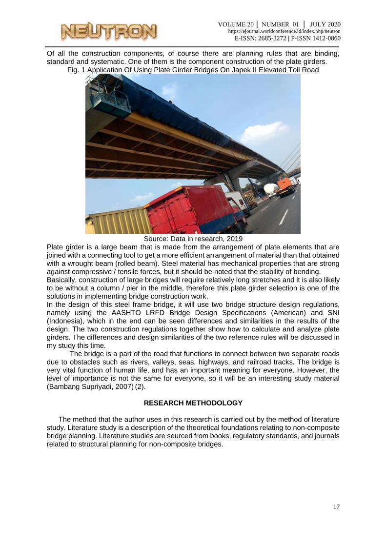
Of all the construction components, of course there are planning rules that are binding, standard and systematic. One of them is the component construction of the plate girders.
Fig. 1 Application Of Using Plate Girder Bridges On Japek II Elevated Toll Road
Source: Data in research, 2019
Plate girder is a large beam that is made from the arrangement of plate elements that are joined with a connecting tool to get a more efficient arrangement of material than that obtained with a wrought beam (rolled beam). Steel material has mechanical properties that are strong against compressive / tensile forces, but it should be noted that the stability of bending. Basically, construction of large bridges will require relatively long stretches and it is also likely to be without a column / pier in the middle, therefore this plate girder selection is one of the solutions in implementing bridge construction work. In the design of this steel frame bridge, it will use two bridge structure design regulations, namely using the AASHTO LRFD Bridge Design Specifications (American) and SNI (Indonesia), which in the end can be seen differences and similarities in the results of the design. The two construction regulations together show how to calculate and analyze plate girders. The differences and design similarities of the two reference rules will be discussed in my study this time.
The bridge is a part of the road that functions to connect between two separate roads due to obstacles such as rivers, valleys, seas, highways, and railroad tracks. The bridge is very vital function of human life, and has an important meaning for everyone. However, the level of importance is not the same for everyone, so it will be an interesting study material (Bambang Supriyadi, 2007) (2).
RESEARCH METHODOLOGY
The method that the author uses in this research is carried out by the method of literature
study. Literature study is a description of the theoretical foundations relating to non-composite bridge planning. Literature studies are sourced from books, regulatory standards, and journals related to structural planning for non-composite bridges.
VOLUME 20 │ NUMBER 01 │ JULY 2020 https://ejournal.worldconference.id/index.php/neutron
E-ISSN: 2685-3272 | P-ISSN 1412-0860
Deck has dimensions: cross-sectional area Adeck = 0.4 m2 Concrete specific gravity ϒconcrete = 25 kN/m3 Then the deck load = Adeck x ϒbeton =10 kN/m
1.3 Diaphragm Weight Diaphragm has dimensions: Diaphragm volume V = 0.006096 m3 Steel specific gravity ϒsteel = 78.5 kN / m3
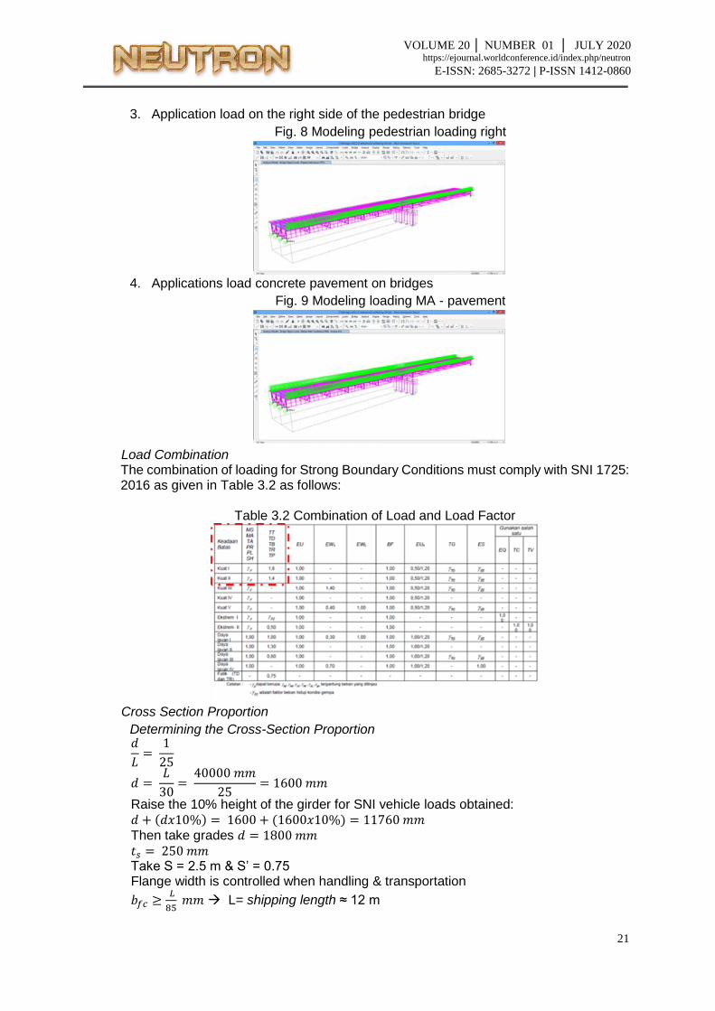
2. Additional Dead Load / Utilities (MA) 2.1 Load Pavement
Concrete specific gravity ϒconcrete = 25 kN/m3 wide sidewalk Asidewalk = 0.189 m2 Load of sidewalk qsidewalks =25 x 0.198=4.73 kN/m (per side)
2.2 Ralling Loads Concrete specific gravity ϒconcrete = 25 kN/m3 Wide railing concrete Arall = 0.196 m2 Load concrete railing qrall = 25 x 0.196= 4.90 kN / m (per side)
2.3 Asphalt Loads Asphalt density ϒasphalt = 22.4 kN / m3 Asphalt thickness tasphalt= 0.05 m Road width broad= 7 m Asphalt loads qasphalt = 22.4 x 0.05 x 7 = 7.84 kN / m (per entire bridge width)
2.4 Concrete Screed Loads Concrete specific gravity ϒconcrete = 25 kN/m3 Concrete screed area Ascreed = 0.35 m3 Concrete screed load qscreed = 25 x 0.35 = 8.75 kN/m(per entire bridge width) Then the total MA load = 35.85 kN/m (per entire bridge width)
And for the total MA load per girder = 35.85
4 = 8.96 kN/m
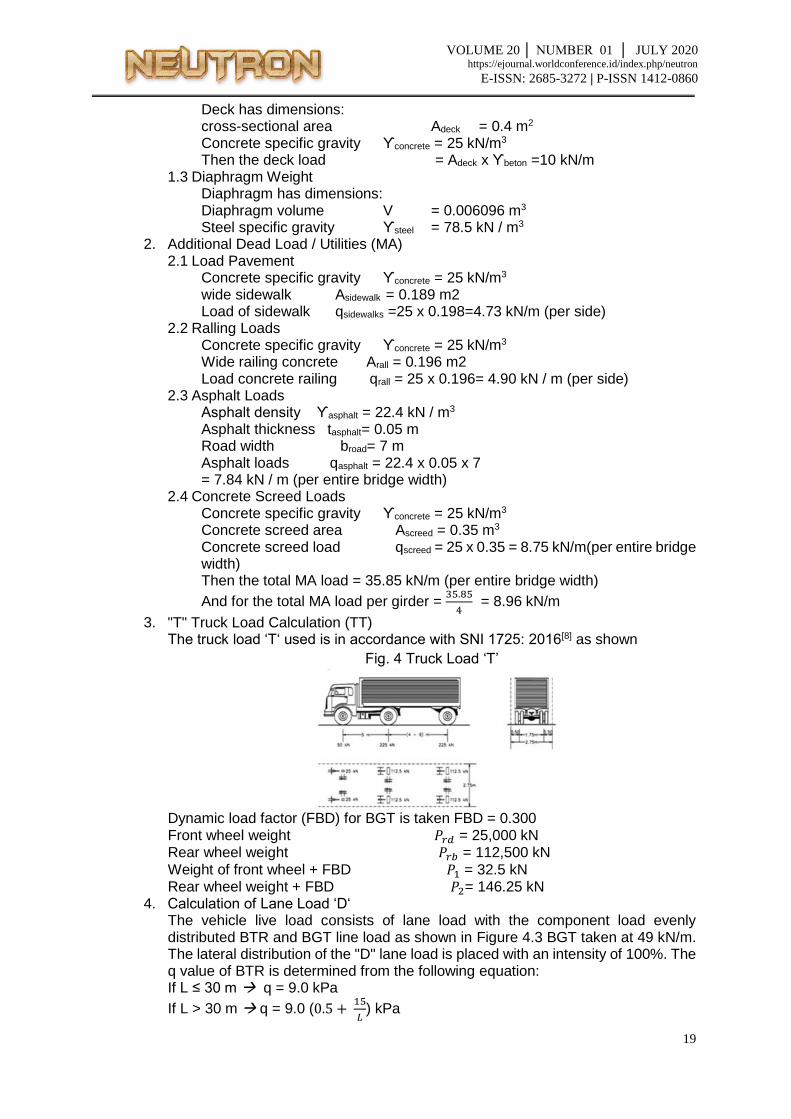
3. "T" Truck Load Calculation (TT) The truck load ‘T‘ used is in accordance with SNI 1725: 2016[8] as shown
Fig. 4 Truck Load ‘T’
Dynamic load factor (FBD) for BGT is taken FBD = 0.300 Front wheel weight 𝑃𝑟𝑑 = 25,000 kN Rear wheel weight 𝑃𝑟𝑏 = 112,500 kN
Weight of front wheel + FBD 𝑃1 = 32.5 kN Rear wheel weight + FBD 𝑃2= 146.25 kN
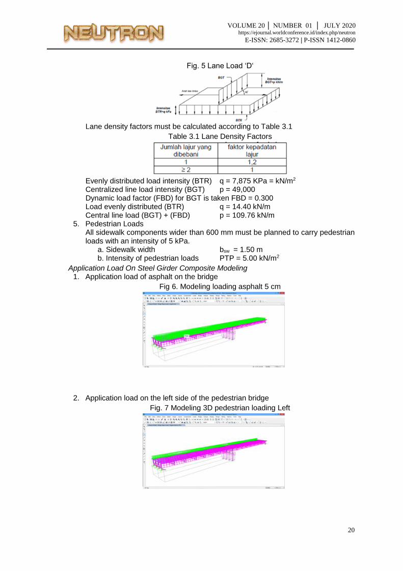
4. Calculation of Lane Load ‘D‘ The vehicle live load consists of lane load with the component load evenly distributed BTR and BGT line load as shown in Figure 4.3 BGT taken at 49 kN/m. The lateral distribution of the "D" lane load is placed with an intensity of 100%. The q value of BTR is determined from the following equation: If L ≤ 30 m q = 9.0 kPa
VOLUME 20 │ NUMBER 01 │ JULY 2020 https://ejournal.worldconference.id/index.php/neutron
E-ISSN: 2685-3272 | P-ISSN 1412-0860
𝑏𝑓𝑐 ≥ 12𝑜𝑜𝑜
85 = 142 𝑚𝑚 ≥ 300 𝑚𝑚 𝑏𝑓𝑐 ≥ 300 𝑚𝑚
The minimum flange thickness for a straight bridge is 19 mm, so take: Thick flange upper = 20 mm Thick flange bottom = 20 mm So for web height D = 1800-20-20 = 1760 mm Minimum web thickness of 12 mm, take tw = 14 mm Check the flange proportion requirements:
𝑏𝑓 ≥ 𝐷
6 =
1760
6 = 293.33 𝑚𝑚
Use bf = 350 for the upper and lower flanges 𝑏𝑓
2𝑡𝑓≤ 9.2 =
350
2𝑥20 = 8.75 < 9.2 (top flens NSBA)
𝑏𝑓
2𝑡𝑓≤ 9.2 =
350
2𝑥20 = 8.75 < 9.2 (bottom flens NSBA)
Then from the data above we get the following cross-section proportions: Steel IWF 1800.300.14.20 d = 1800 mm bf = 300 mm tw = 14 mm tf = 20 mm tb = 20 mm L = 40 m Fc’ = 40 MPa Fy = 345 MPa Dw = 1760 mm
Ec = 4700√𝑓𝑐′ = 29725.41 MPa
Es = 200000 MPa
n = 𝐸𝑠
𝐸𝑐 = 6.728
Examination of Proportion Limits for Profile Cross-section The cross-section proportion must be checked to ensure the stability of the profile used meets the requirements. Determination of the cross-section proportion set in the AASHTO LRFD Bridge Design Specifications 2017 Article 6.10.2:
In accordance with AASHTO LRFD Bridge Design Specifications 2017 article 6.10.2.1.1-1
1. Proportion of Body Plate Without Stiffener Calculated as follows: 𝐷𝑤
𝑡𝑤=
1760
14 = 125.71 𝑚𝑚
Check web stability = 𝐷𝑤
𝑡𝑤≤ 150 → 125.71 ≤ 150, then including slim web.
2. Proportion of Wing Plate Sections In accordance with AASHTO LRFD Bridge Design Specifications 2017 article 6.10.2.2, for cross section of wing plate as follows: AASHTO LRFD 2017 6.10.2.2-1
VOLUME 20 │ NUMBER 01 │ JULY 2020 https://ejournal.worldconference.id/index.php/neutron
E-ISSN: 2685-3272 | P-ISSN 1412-0860
0.1 ≤𝐼𝑦𝑐
𝐼𝑦𝑡≤ 10
𝐼𝑦𝑐 =𝑡𝑓 . 𝑏𝑓
3
12=
0.020 . 0.0252
12= 0.000042 𝑚4
𝐼𝑦𝑡 =𝑡𝑓 . 𝑏𝑓
3
12=
0.020 . 0.0252
12= 0.000042 𝑚4
0.1 ≤𝐼𝑦𝑐
𝐼𝑦𝑡≤ 10
0.1 ≤ 1 ≤ 10
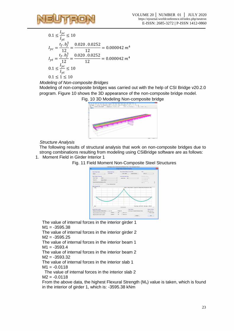
Modeling of Non-composite Bridges Modeling of non-composite bridges was carried out with the help of CSI Bridge v20.2.0
program. Figure 10 shows the 3D appearance of the non-composite bridge model.
Fig. 10 3D Modeling Non-composite bridge
Structure Analysis The following results of structural analysis that work on non-composite bridges due to strong combinations resulting from modeling using CSiBridge software are as follows:
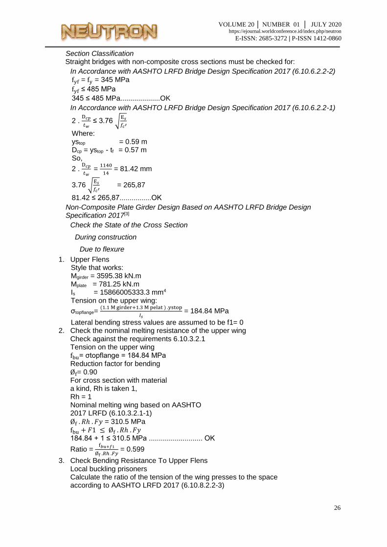
1. Moment Field in Girder Interior 1
Fig. 11 Field Moment Non-Composite Steel Structures
The value of internal forces in the interior girder 1 M1 = -3595.38 The value of internal forces in the interior girder 2 M2 = -3595.25 The value of internal forces in the interior beam 1 M1 = -3593.4 The value of internal forces in the interior beam 2 M2 = -3593.32 The value of internal forces in the interior slab 1 M1 = -0.0118 The value of internal forces in the interior slab 2 M2 = -0.0118 From the above data, the highest Flexural Strength (Mu) value is taken, which is found in the interior of girder 1, which is: -3595.38 kNm
VOLUME 20 │ NUMBER 01 │ JULY 2020 https://ejournal.worldconference.id/index.php/neutron
E-ISSN: 2685-3272 | P-ISSN 1412-0860
2. Slide Field On Girder Interior 1
Fig. 12 Shear Force Non-Composite Steel Structures
The value of the shear force on the interior of the girder 1 V1 = -449.9968 The value of the shear force on the interior of the girder 2 V2 = -449.9818 The value of the shear force on the interior beam 1 V1 = -442.4905 The value of the shear force on the interior beam 2 V2 = -442.4755 The value of the shear force on the interior of the slab 1 V1 = -7.5063 The value of the shear force on the interior of the slab 2 V2 = -7.5063 From the above data, the largest Shear Force (Vu) value is taken, which is found in the interior of girder 1, which is: -449.9968 kNm
Calculation of Inertia and Center of Cross Section In the calculation of inertia and cross-section emphasis is done using Microsoft Excel and obtained the following data:
Non Composite Elastic Flexural Section Properties Fig. 13 Non Composite Elastic Flexural Section Properties
VOLUME 20 │ NUMBER 01 │ JULY 2020 https://ejournal.worldconference.id/index.php/neutron
E-ISSN: 2685-3272 | P-ISSN 1412-0860
Section Classification Straight bridges with non-composite cross sections must be checked for:
In Accordance with AASHTO LRFD Bridge Design Specification 2017 (6.10.6.2.2-2) fyf = fy = 345 MPa
fyf ≤ 485 MPa
345 ≤ 485 MPa....................OK
In Accordance with AASHTO LRFD Bridge Design Specification 2017 (6.10.6.2.2-1)
2 . D𝑐𝑝
𝑡𝑤 ≤ 3.76 √
E𝑠
𝑓𝑐′
Where: ystop = 0.59 m Dcp = ystop - tf = 0.57 m So,
2 . D𝑐𝑝
𝑡𝑤 =
1140
14 = 81.42 mm
3.76 √E𝑠
𝑓𝑐′ = 265,87
81.42 ≤ 265,87................OK
Non-Composite Plate Girder Design Based on AASHTO LRFD Bridge Design Specification 2017[3]
Check the State of the Cross Section
During construction
Due to flexure
1. Upper Flens Style that works: Mgirder = 3595.38 kN.m Mplate = 781.25 kN.m Is = 15866005333.3 mm4 Tension on the upper wing:
σtopflange= (1.1 M girder+1.3 M pelat ) .ystop
𝐼𝑠 = 184.84 MPa
Lateral bending stress values are assumed to be f1= 0 2. Check the nominal melting resistance of the upper wing
Check against the requirements 6.10.3.2.1 Tension on the upper wing fbu= σtopflange = 184.84 MPa Reduction factor for bending Øf= 0.90 For cross section with material a kind, Rh is taken 1, Rh = 1 Nominal melting wing based on AASHTO 2017 LRFD (6.10.3.2.1-1)
3. Check Bending Resistance To Upper Flens Local buckling prisoners Calculate the ratio of the tension of the wing presses to the space according to AASHTO LRFD 2017 (6.10.8.2.2-3)
VOLUME 20 │ NUMBER 01 │ JULY 2020 https://ejournal.worldconference.id/index.php/neutron
E-ISSN: 2685-3272 | P-ISSN 1412-0860
λf = bf
2𝑡𝑓 =
0,300
2 . 0,02 = 7.5
Calculate the limit of the slope to plate ratio Compact compressive wing to suit AASHTO LRFD 2017 (6.10.8.2.2-4)
λpf = 0.38 √E𝑠
𝑓𝑦 = 9.149
If λf ≤ λpf
7.5 ≤ 9.149 then local buckling prisoners from upper wing is Fnc FLB = RbRhfy
Calculate the limit of slenderness ratio for plates noncompact body
λrw = 5.7 √E𝑠
𝑓𝑦 = 137.24
Calculate the value of the web loading shedding factor (Rb) Factor Rb = 1 for strength checking when constructibility and if conditions the following are met: For a positive bending composite cross section without a longitudinal stiffner that
meets the following requirements:
D
𝑡𝑤 ≤ 150
1760
14 = 125.71 ≤ 150 ........ OK
Then the local buckling resistance in the upper wing according to AASHTO LRFD 2017 (6.10.8.2.2-1) is: Fnc FLB = RbRhfyc = 345 MPa
Lateral torque bend resistance Lb = 5 m Effective grating radius for lateral torsion (rt) bending according to AASHTO LRFD 2017 (6.10.8.2.3-9)
rt = bf
√12 ( 1+1
3 .
𝐷 .𝑡𝑤
𝑏𝑓 .𝑡𝑓
= 0,300
√12 ( 1+1
3 .(
1,760 . 0,014
0,300 . 0,020))
= 0.081 m
Length without bracing (Lp) according to AASHTO LRFD 2017 (6.10.8.2.3-4)
Lp = 1.0 . rt . √E𝑠
𝑓𝑦 = 1.0 . 0.081 . √
200000
345 = 1.950 m
Length without bracing (Lr) according to AASHTO LRFD 2017 (6.10.8.2.3-5)
5. Body Plates (web) To ensure that bending does not occur on the web during the construction process the requirements in equation 6.10.3.2.1-3 must be met, Fbu ≤ ØFcrw Bend the bending coefficient
K = 9
(𝐷𝑐
𝐷)2
= 9
(880
1760)2
= 36
Prisoners bend in the body
Fcrw = 0.95 .Es .k
(𝐷
𝑡𝑤)2
= 0.95 .200000 .36
(1760
14)2
= 432.80
However, the Fcrw value cannot be more big from: Fye = Fy = 345 MPa Fyw = Fy = 345 MPa 𝑅ℎ . 𝑓𝑦𝑒 = 345 MPa f𝑦𝑤
0.7 = 492.857 MPa
then the bending prisoners in the body are:
Fcrw =min (𝑓𝑐𝑟𝑤,𝑅ℎ . 𝑓𝑦𝑒 ,f𝑦𝑤
0.7) = 345 MPa
Øf . Fcrw = 0.90 x 345 = 310.5 MPa Check bending resistance in the body
Fbu ≤ Øf.Fcrw 184.84 MPa ≤ 310.5 MPa ............... OK
Ratio = f𝑏𝑢
Øf .𝐹𝑐𝑟𝑤 = 0.595
In this study, the examination of the cross-section boundary conditions due to shear, service boundary conditions and fatigue boundary conditions are not included or not calculated. And go directly to the calculation phase of the strong boundary conditions.
Strong Boundary Conditions
Due to Flexure
1. Determination of Plastic Neutral Axes Based on Table D.6.1.1 AASHTO LRFD 2017 Compressed wing width bcf = 300 mm Compressed wing thickness tcf = 20 mm Wing width btf = 300 mm Wing thickness tft = 20 mm Web height Dw = 1760 mm Web thickness tw = 14 mm Force plate press plate Ps = 0.85.fc’.bef.hs = 1700 kN Axial force on the reinforcement of the deck plate Prt = 0 kN
VOLUME 20 │ NUMBER 01 │ JULY 2020 https://ejournal.worldconference.id/index.php/neutron
E-ISSN: 2685-3272 | P-ISSN 1412-0860
Axial force on the reinforcement under the deck plate Prb = 0 kN Axial force on the upper wing PC = Bcf. tcf ⋅ fy = 2484 kN
Axial force on the web Pw = Dw. tw ⋅ fy = 8500.5 kN Axial force on the lower wing Pt = btf. ttf ⋅ fy = 2070 kN Case I Pt + Pw = 10570.5 kN Pc + Ps + Prb + Prt = 4184 kN Case II Pt + Pw + Pc = 13054.5 kN Ps + Prb + Prt = 1700 kN Because Case II meets the requirements, the PNA is in the upper wing, so:
𝑌 = (𝑡𝑐𝑓
2) . (
𝑃𝑤 + 𝑃𝑡 − 𝑃𝑠 − 𝑃𝑟𝑡 − 𝑃𝑟𝑏
𝑃𝑐+ 1)
𝑌 = 89.9 𝑚𝑚 2. Check ductility according to AASHTO LRFD 2017 6.10.7.3-1
Dp ≤ 0.42Dt Distance from the top edge of the concrete deck to the neutral axis of the composite cross section at a plastic moment (Dp) Dp = hs + tcf + Y = 129.9 mm Total height of composite cross section (Dt) Dt = D + hs = 1.82 m 0.42Dt = 764.4 mm Dp ≤ 0.42Dt 129.9 ≤ 764.4 ... OK
3. Check steel compact section according to AASHTO LRFD 2017 6.10.7.1.2-1 Dp ≤ 0.1Dt 0.1Dt = 182 mm 182 ≤ 764.4 ... OK
4. Calculation of AASHTO LRFD 2017 plastic moment D6.1-2 Dt = tcf + Dw + ttf/2 - Y = 1700.1 mm ds = hs/2 + tcf + Y = 119.9 mm dw = Dw/2 + ttf - Y = 810.1 mm drt = 0 mm drb = 0 mm So that the plastic moment can be calculated by:
VOLUME 20 │ NUMBER 01 │ JULY 2020 https://ejournal.worldconference.id/index.php/neutron
E-ISSN: 2685-3272 | P-ISSN 1412-0860
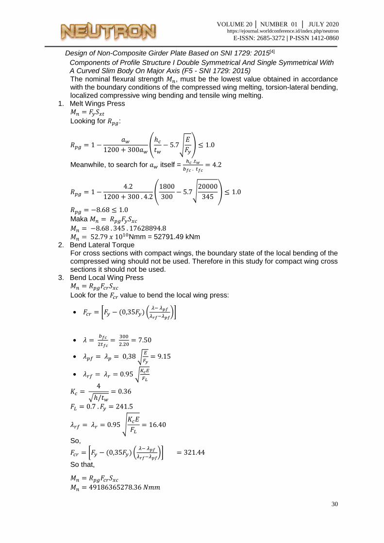
Design of Non-Composite Girder Plate Based on SNI 1729: 2015[4]
Components of Profile Structure I Double Symmetrical And Single Symmetrical With A Curved Slim Body On Major Axis (F5 - SNI 1729: 2015) The nominal flexural strength 𝑀𝑛, must be the lowest value obtained in accordance with the boundary conditions of the compressed wing melting, torsion-lateral bending, localized compressive wing bending and tensile wing melting.
For cross sections with compact wings, the boundary state of the local bending of the compressed wing should not be used. Therefore in this study for compact wing cross sections it should not be used.
3. Bend Local Wing Press 𝑀𝑛 = 𝑅𝑝𝑔𝐹𝑐𝑟𝑆𝑥𝑐
Look for the 𝐹𝑐𝑟 value to bend the local wing press:
VOLUME 20 │ NUMBER 01 │ JULY 2020 https://ejournal.worldconference.id/index.php/neutron
E-ISSN: 2685-3272 | P-ISSN 1412-0860
= 49186.37 𝑘𝑁𝑚 4. Melt Wing Pull
𝑀𝑛 = 𝐹𝑦𝑆𝑥𝑡
𝑀𝑛 = 345 . 17628894.8 𝑀𝑛 = 6081968706 𝑁𝑚𝑚
𝑀𝑛 = 6081.97 𝑘𝑁𝑚 From the results of the whole calculation, the smallest 𝑀𝑛 value is taken, the 𝑀𝑛 value which is in the tensile wing melting of 6081.97 kNm.
Comparation of Similarities and Differences Below is a table of comparative results between the AASHTO LRFD Bridge Design Specification 2017 code with the SNI 1729: 2015 code in the planning of bending non-composite plate girder bridge design:
Table 3.3 Comparative Results Table
CLOSING In this chapter, the authors provide conclusions and suggestions relating to the results that
the authors examined. The conclusion was obtained from the results of the analysis and interpretation of existing data. Meanwhile, suggestions are given as reference material in subsequent studies.
CONCLUSIONS From the comparative studies that have been made, some conclusions can be drawn, as follows:
1. In planning the plate girder bending using AASHTO LRFD Bridge Design Specifications 2017 gives a greater ØMn value so that a smaller profile dimension can be used than the results of planning using SNI 1729: 2015.
2. On the contrary, planning for plate girder bending using SNI 1729: 2015 results in a smaller ØMn value so that the dimensions of the profile used are greater than the results of planning using AASHTO LRFD Bridge Design Specifications 2017.
3. The results of planning the flexible plate girder using the AASHTO LRFD Bridge Design Specifications 2017 regulations are much safer when compared to the results of the design using SNI 1729: 2015 regulations.
From the values obtained it can be concluded that the two regulations namely AASHTO LRFD Bridge Design Specifications 2017 and SNI 1729: 2015 in the stability planning of non-composite plate girder bridges produce a safe and strong plan because they meet the applicable provisions namely Moment (Mu <ØMn ).
Suggestions From the comparative studies that have been carried out, several things that can be developed in further research are as follows:
1. It is necessary to compare non-composite bridge planning based on AASHTO LRFD Bridge Design Specifications 2017 and SNI 1729: 2015 for Constructability, Serviceability, Fatigue and Fracture.
VOLUME 20 │ NUMBER 01 │ JULY 2020 https://ejournal.worldconference.id/index.php/neutron
E-ISSN: 2685-3272 | P-ISSN 1412-0860
2. It is necessary to compare the planned budget of the design results of the non-composite plate girder bridge design based on AASHTO LRFD Bridge Design Specifications 2017 and SNI 1729: 2015.
REFERENCES
[1] Bakosurtanal. Badan Informasi Geospasial. Bakosurtanal. [Online] 2014. http://www.bakosurtanal.go.id.
[2] Supriyadi, Bambang and Muntohar, A. S. Jembatan. Yogyakarta : Beta Offset, 2007. [3] AASHTO. AASHTO LRFD Bridge Design Specifications 8th Edition. Washington, DC :
American Association of State Highway and Transportation Officials, 2017. [4] Indonesia, Standar Nasional. SNI 1729:2015 Spesifikasi untuk Bangunan Gedung
Baja Struktural. Jakarta : Badan Standardisasi Nasional, 2015. [5] AISC. An American National Standard ANSI/AISC 360-10 : Load Specification for
Structural Steel Buildings. Chicago : American Institute of Steel Construction, Inc., 2010.
[6] Dewobroto, W. Struktur Baja Perilaku, Analisis & Desain–AISC 2010 Edisi ke-2. Tanggerang : Penerbit Jurusan Teknik Sipil UPH, 2016.
[7] Setiawan, A. Perencanaan Struktur Baja Dengan Metode LRFD. Semarang : Erlangga, 2008.
[8] Indonesia, Standar Nasional. SNI 1725:2016 Pembebanan Untuk Jembatan. Jakarta : Badan Standardisasi Nasional, 2016.
[9] Situstekniksipil.com. Klasifikasi Jembatan. Situstekniksipil. [Online] 23 October 2017. https://www.situstekniksipil.com/2017/10/klasifikasi-jembatan.html.
[11] Essen, Donald. Sesi 06 – Perencanaan Struktur Baja Berdasarkan AASHTO LRFD Bridge Design Specifications 8th Edition. Pertamina University, Jakarta, Jakarta, Indonesia : s.n., 2-5 September 2019


![CSP00014[CIVIL-Tutorial]Composite Plate Girder Design-EC4](https://static.documents.pub/doc/80x56/55cf9353550346f57b9d4962/csp00014civil-tutorialcomposite-plate-girder-design-ec4.jpg)


