65 International Journal of Recent Research and Review, Vol. XII, Issue 1, March 2019 ISSN 2277 – 8322 Comparative Analysis of Results for Design of Gravitational G+1 RCC Framed Structure via Using STAAD Pro Series 4.0 and E-TABS 2015 Rishanksharma 1 , Mahendra Saini 2 Kautiliya Institute of Technology & Engineering, Sitapura, Jaipur, Rajasthan, India 302022 1 [email protected], 2 [email protected]Abstract— Computer is the main tool in today’s technological world and use of computers has been prominent in almost every field. In structural design there are two major leading software’s which are STAAD PRO and E-TABS. In this research paper we have designed a gravitationally loaded G+1 RCC structure via using STAAD PRO and E-TABS. In this we will design structure with all the steps to be used in the software’s and we will compare the output results of both the software’s with each other and we will see that which software holds an advantage over the other software and what are the reasons for that as well as we will compare both the results and conclude that which software should be used in designing of RCC structure for following structure which software provides best results among both the software’s. Keywords—Gravitationally, RCC, Methodology, STAAD PRO, E-TABS. I. INTRODUCTION Structural engineering is one field which is expanding as the requirements of bigger structures are being required to compensate increasing population demand and as the structure becomes more difficult to design manual calculations become laborious so to counter such a problem computer software’s have been developed to design a structure with such a precision which cannot be attain with manual calculation. In the following research we are designing a structure which is having some major components as members which are beams, columns and slabs and IS code parameters are present initially in the software’s itself Since the 1990s specialist software has become available to help in design of structure with the functions such as the drawing , analyzing and designing of structures with highest precisions, example includes AutoCAD, STAAD.PRO, ETABS, REVIT structure, etc. such software may also take into consideration environmental loads such as from earth quakes and wind. There are two major software’s in the design of a structure is E-TABS and STAAD PRO which are used widely by the structural designers across the world. A. STAAD PRO V8i STAAD or (STAAD.PRO) was developed by yorbalinda, CA in 1997 as a structural design and analysis program which was later bought by bentely systems in 2005. STAAD Pro is commercially used worldwide for design and analysis of various structures such as steel, concrete and timber etc. We can perform various analyses such as 1 st order analysis, 2 nd order analysis (p-delta analysis) geometric nonlinear analysis, static nonlinear analysis, buckling analysis as well as we can perform dynamic analysis from modal extraction to time history and response spectrum analysis. We can design various types of structures by using STADD PRO such as space structure, plane structure, truss structure and floor structure and can generate designs in 3-d model structure which makes a site engineer work of propagation of structure easy as he is provided with diagrammatic representation of structure. B. E-TABS (2015) The innovative and revolutionary new ETABS is the ultimate integrated software package for the structural analysis and design of buildings. Incorporating 40 years of continuous research and development, this latest ETABS offers unmatched 3D object based modeling and visualization tools, blazingly fast linear and nonlinear analytical power, sophisticated and comprehensive design capabilities for a wide-range of materials, and insightful graphic displays, reports, and schematic drawings that allow users to quickly and
Transcript
65
International Journal of Recent Research and Review, Vol. XII, Issue 1, March 2019 ISSN 2277 – 8322
Comparative Analysis of Results for Design of Gravitational G+1 RCC Framed Structure via Using STAAD Pro Series
4.0 and E-TABS 2015 Rishanksharma1, Mahendra Saini2
Abstract— Computer is the main tool in today’s technological world and use of computers has been prominent in almost every field. In structural design there are two major leading software’s which are STAAD PRO and E-TABS. In this research paper we have designed a gravitationally loaded G+1 RCC structure via using STAAD PRO and E-TABS. In this we will design structure with all the steps to be used in the software’s and we will compare the output results of both the software’s with each other and we will see that which software holds an advantage over the other software and what are the reasons for that as well as we will compare both the results and conclude that which software should be used in designing of RCC structure for following structure which software provides best results among both the software’s. Keywords—Gravitationally, RCC, Methodology, STAAD PRO, E-TABS.
I. INTRODUCTION
Structural engineering is one field which is expanding as the requirements of bigger structures are being required to compensate increasing population demand and as the structure becomes more difficult to design manual calculations become laborious so to counter such a problem computer software’s have been developed to design a structure with such a precision which cannot be attain with manual calculation. In the following research we are designing a structure which is having some major components as members which are beams, columns and slabs and IS code parameters are present initially in the software’s itself
Since the 1990s specialist software has become available to help in design of structure with the functions such as the drawing , analyzing and designing of structures with highest precisions, example includes AutoCAD, STAAD.PRO, ETABS, REVIT structure, etc. such software may also take into consideration environmental loads such as from earth quakes and wind.
There are two major software’s in the design of a structure is E-TABS and STAAD PRO which are used widely by the structural designers across the world.
A. STAAD PRO V8i
STAAD or (STAAD.PRO) was developed by yorbalinda, CA in 1997 as a structural design and analysis program which was later bought by bentely systems in 2005.
STAAD Pro is commercially used worldwide for design and analysis of various structures such as steel, concrete and timber etc.
We can perform various analyses such as 1st order analysis, 2nd order analysis (p-delta analysis) geometric nonlinear analysis, static nonlinear analysis, buckling analysis as well as we can perform dynamic analysis from modal extraction to time history and response spectrum analysis.
We can design various types of structures by using STADD PRO such as space structure, plane structure, truss structure and floor structure and can generate designs in 3-d model structure which makes a site engineer work of propagation of structure easy as he is provided with diagrammatic representation of structure.
B. E-TABS (2015)
The innovative and revolutionary new ETABS is the ultimate integrated software package for the structural analysis and design of buildings. Incorporating 40 years of continuous research and development, this latest ETABS offers unmatched 3D object based modeling and visualization tools, blazingly fast linear and nonlinear analytical power, sophisticated and comprehensive design capabilities for a wide-range of materials, and insightful graphic displays, reports, and schematic drawings that allow users to quickly and
66
easily decipher and understand analysis and design results.
From the start of design conception through the production of schematic drawings, ETABS integrates every aspect of the engineering design process. Creation of models has never been easier - intuitive drawing commands allow for the rapid generation of floor and elevation framing. CAD drawings can be converted directly into ETABS models or used as templates onto which ETABS objects may be overlaid. The state-of-the-art SAP Fire 64-bit solver allows extremely large and complex models to be rapidly analyzed, and supports nonlinear modeling techniques such as construction sequencing and time effects (e.g., creep and shrinkage).
C. Gravitationally Loaded Structure
The gravitationally loaded structure is the structure under the influence of load that acts under gravitational force. In such a structure there are forces which act vertically downward along the columns. The forces which come in this category are dead load and live loads the forces which act perpendicular to structure is not included in this such as wind load and seismic load.
II. LITERATURE REVIEW While designing a structure in a software we need to understand the working of a software and what it has to offer to our design which can help us to understand the software and the summarize detail of a software is told in the overview of the softwares.
A. Over view of E-TABS
E-TABs stand for extended three dimensional analysis of building system. It has been used in one of the structural marvels BURJ KHALIFA. We can design any type of building by using E-TABS. This helps in taking advantage of unique physical properties of building type structure. It has got a better graphical modeler and post processor for viewing all results.
E-TABS provide both static and dynamic analysis with gravity, thermal and lateral loads. In dynamic analysis seismic response spectrum is used. E-TABS can analyze any combination of frames and walls. Every code is provided with a cutting edgeto use the unique qualities of members. As outputs we can see story displacement, mode shapes and frame displacement.
ETABS provides the numerical and visual data for each member of structure in the form of concrete column schedule and reinforcement table for beam and to see the physical view of structure is seen by reinforcement detail diagram.
B. Over view of STAAD PRO STAAD stands for structural analysis and design with the help of STAAD PRO we can design buildings bridges tanks etc. Analysis of structure is done via using moment distribution method which is based on load transferring of beam to supports. To use moment distribution we assume a cross-section for the spans of continuous being to analyze the frame stiffness Matrix method is used which depend upon matrices. Matrix method for analyzing was firstly used by STAAD PRO and stiffness analysis was done by displacement method in STAAD PRO discrete elements are created by software for analysis. The equilibrium conditions with displacement compatibility at the joints are achieved. It provides us with graphical model generation to design a structure we go through series of process such as modeling sectional properties loading, support system analysis and designing. Design engine of STAAD PRO consist of code checking and optimization of steel, aluminum and Timber members. Reinforcement calculations of all RCC structures are provided. Results are viewed in both manners in the form of of visuals as well as in the form of calculation in report with warning and errors, if they are present. It gives a detailed report of RCC steel and Timber design.
III. DESIGN OF G+1 RCC FRAMED STRCTURE IN STAAD PRO SERIES 4.0.
In the designing of a RCC structure via using STAAD PRO (series 4.0) we have to through following step as explained down below but most important thing is design the structure with right code to design a structure as per Indian provisional laws we need to design our structure by choosing IS 456: 2000 and to design the structure via using STAAD PRO.
A. Design Problem Data
A superficial structure G+1 gravitationally loaded framed RCC structure of size 5 m × 5 m consists of 8 beams and 8 columns with specification as follows :-
Column of size at ground floor = 0.5 m × 0.5 m
67
Column of size at other floors = 0.4 m × 0.4 m
Size of beams of all floors = 0.3 m × 0.5 m
Slab thickness of all floors = 0.2 m
Physical parameters
Length of structure = 1 bays @ 5.0 m = 5 m.
Width of structure = 1 bays @ 5.0 m = 5 m.
Height of structure = 4m + 1 story @ 3.3 m = 7.3 m.
(1.0 m height and .10 m thick parapet wall is considered over all the beams of top story)
Load consideration
• Self-weight of structure • Wall load on the beams of middle story = - 13
Kn /m2. • Wall load on the beams of terrace story = -
4.33 Kn /m2. • Live load on middle story as per IS 875 part 2
= -2.5 Kn /m2. • Live load on top story as per IS 875 part 2 =
0.75 Kn /m2.
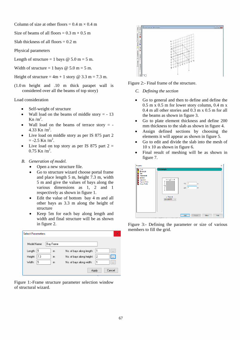
B. Generation of model. • Open a new structure file. • Go to structure wizard choose portal frame
and place length 5 m, height 7.3 m, width 5 m and give the values of bays along the various dimensions as 1, 2 and 1 respectively as shown in figure 1.
• Edit the value of bottom bay 4 m and all other bays as 3.3 m along the height of structure
• Keep 5m for each bay along length and width and final structure will be as shown in figure 2.
Figure 1:-Frame structure parameter selection window of structural wizard.
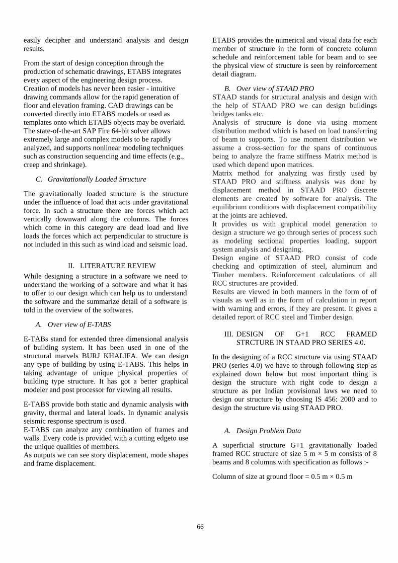
Figure 2:- Final frame of the structure.
C. Defining the section
• Go to general and then to define and define the 0.5 m x 0.5 m for lower story column, 0.4 m x 0.4 m all other stories and 0.3 m x 0.5 m for all the beams as shown in figure 3.
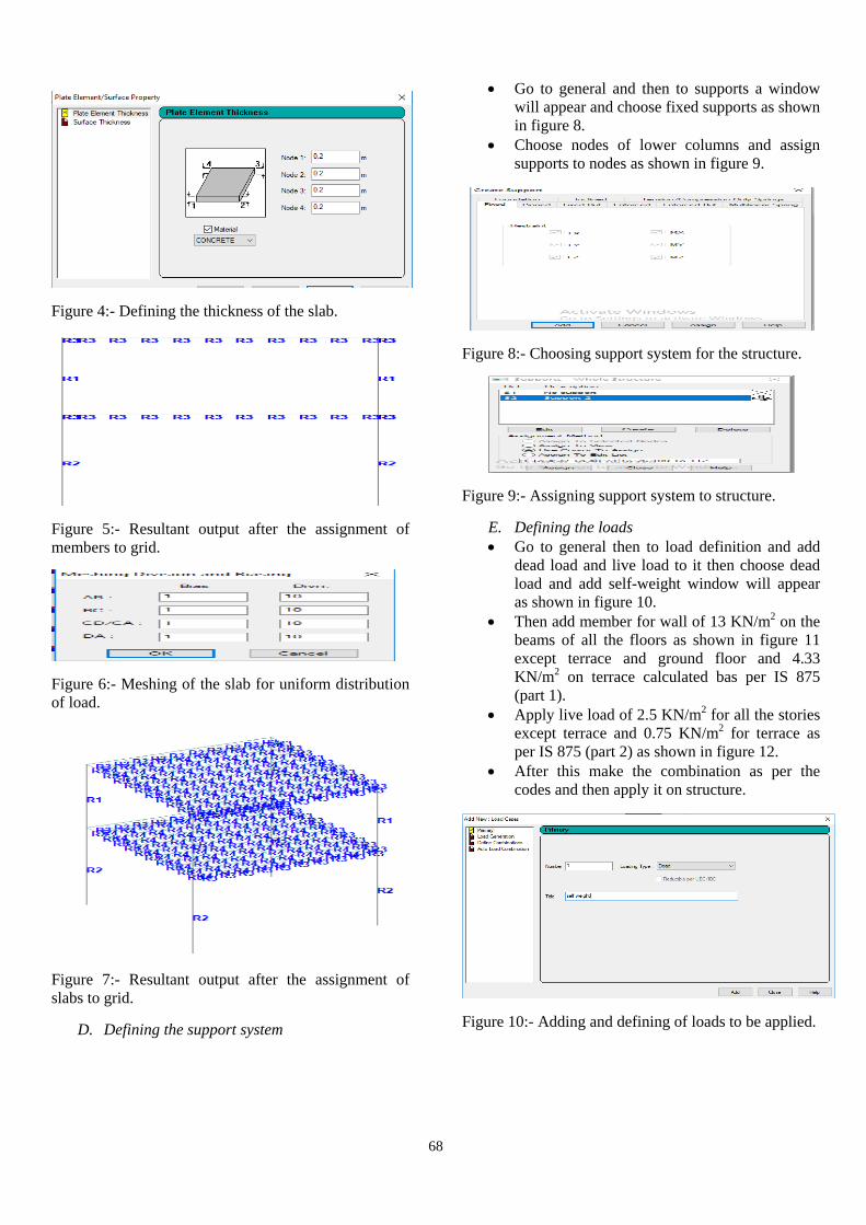
• Go to plate element thickness and define 200 mm thickness to the slab as shown in figure 4.
• Assign defined sections by choosing the elements it will appear as shown in figure 5.
• Go to edit and divide the slab into the mesh of 10 x 10 as shown in figure 6.
• Final result of meshing will be as shown in figure 7.
Figure 3:- Defining the parameter or size of various members to fill the grid.
68
Figure 4:- Defining the thickness of the slab.
Figure 5:- Resultant output after the assignment of members to grid.
Figure 6:- Meshing of the slab for uniform distribution of load.
Figure 7:- Resultant output after the assignment of slabs to grid.
D. Defining the support system
• Go to general and then to supports a window will appear and choose fixed supports as shown in figure 8.
• Choose nodes of lower columns and assign supports to nodes as shown in figure 9.
Figure 8:- Choosing support system for the structure.
Figure 9:- Assigning support system to structure.
E. Defining the loads • Go to general then to load definition and add
dead load and live load to it then choose dead load and add self-weight window will appear as shown in figure 10.
• Then add member for wall of 13 KN/m2 on the beams of all the floors as shown in figure 11 except terrace and ground floor and 4.33 KN/m2 on terrace calculated bas per IS 875 (part 1).
• Apply live load of 2.5 KN/m2 for all the stories except terrace and 0.75 KN/m2 for terrace as per IS 875 (part 2) as shown in figure 12.
• After this make the combination as per the codes and then apply it on structure.
Figure 10:- Adding and defining of loads to be applied.
69
Figure 11:- Placing the values of loads as per there definition.
Figure 12:- Assignment window for the loads to their respective members.
F. Analysis of structure • Go to print/analyze and tick all the blocks and
analyze. • Go to analyze and run analysis and the
software will start analyzing our structure and final dialogue window will appear as shown in figure 13.
Figure 13:- Final output window after running
analyzing of structure.
G. Design of RCC structure
• Go to design chooser concrete in it and choose IS 456 as code and define parameter 30000 N/mm2 for concrete 500000 N/mm2 for the reinforcement of primary and secondary.
• Click on command choose design beam, design column and design elements and choose take-off and assign the following to the members as shown in figure 14.
• Again run analysis for the design of members.
Figure 14:- Final window after assignment of various loads to structure and design completion.
IV. DESIGN OF G+1 RCC FRAMED
STRCTURE IN STAAD PRO SERIES 4.0. In the designing of a RCC structure via using E-TABS 2015 we have to through following step as explained down below but most important thing is design the structure with right code to design a structure as per Indian provisional laws we need to design our structure by choosing IS 456: 2000 and design the structure via using E-TABS 2015.
A. Design Problem Data
A superficial structure G+1 gravitationally loaded framed RCC structure of size 5 m × 5 m consists of 8 beams and 8 columns with specification as follows :-
Column of size at ground floor = 0.5 m × 0.5 m
Column of size at other floors = 0.4 m × 0.4 m
Size of beams of all floors = 0.3 m × 0.5 m
Slab thickness of all floors = 0.2 m
Physical parameters
Length of structure = 1 bays @ 5.0 m = 5 m.
Width of structure = 1 bays @ 5.0 m = 5 m.
Height of structure = 4m + 1 story @ 3.3 m = 7.3 m.
70
(2.0 m height and .10 m thick parapet wall is considered over all the beams of top story)
Load consideration
• Self-weight of structure • Wall load on the beams of middle story = - 13
Kn /m2. • Wall load on the beams of terrace story = -
4.33 Kn /m2. • Live load on middle story as per IS 875 part 2
= -2.5 Kn /m2. • Live load on top story as per IS 875 part 2 =
0.75 Kn /m2.
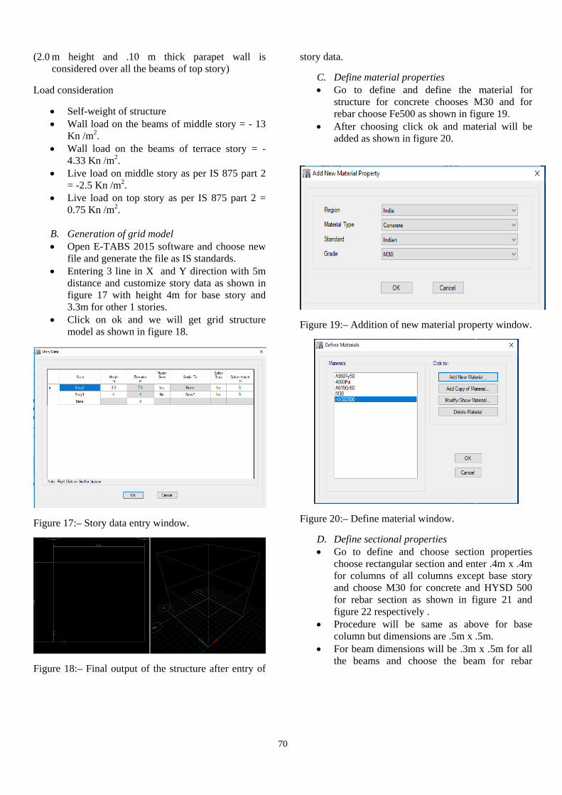
B. Generation of grid model • Open E-TABS 2015 software and choose new
file and generate the file as IS standards. • Entering 3 line in X and Y direction with 5m
distance and customize story data as shown in figure 17 with height 4m for base story and 3.3m for other 1 stories.
• Click on ok and we will get grid structure model as shown in figure 18.
Figure 17:– Story data entry window.
Figure 18:– Final output of the structure after entry of
story data.
C. Define material properties • Go to define and define the material for
structure for concrete chooses M30 and for rebar choose Fe500 as shown in figure 19.
• After choosing click ok and material will be added as shown in figure 20.
Figure 19:– Addition of new material property window.
Figure 20:– Define material window.
D. Define sectional properties • Go to define and choose section properties
choose rectangular section and enter .4m x .4m for columns of all columns except base story and choose M30 for concrete and HYSD 500 for rebar section as shown in figure 21 and figure 22 respectively .
• Procedure will be same as above for base column but dimensions are .5m x .5m.
• For beam dimensions will be .3m x .5m for all the beams and choose the beam for rebar
71
section as shown in figure 23 with same material properties.
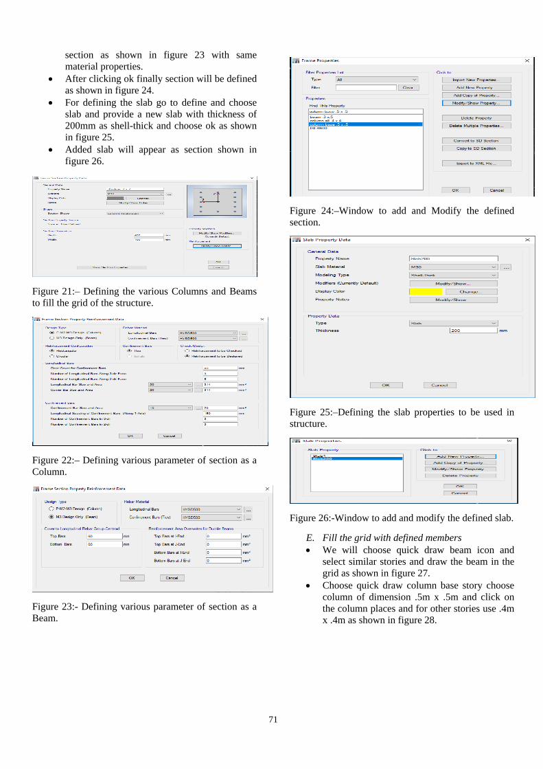
• After clicking ok finally section will be defined as shown in figure 24.
• For defining the slab go to define and choose slab and provide a new slab with thickness of 200mm as shell-thick and choose ok as shown in figure 25.
• Added slab will appear as section shown in figure 26.
Figure 21:– Defining the various Columns and Beams to fill the grid of the structure.
Figure 22:– Defining various parameter of section as a Column.
Figure 23:- Defining various parameter of section as a Beam.
Figure 24:–Window to add and Modify the defined section.
Figure 25:–Defining the slab properties to be used in structure.
Figure 26:-Window to add and modify the defined slab.
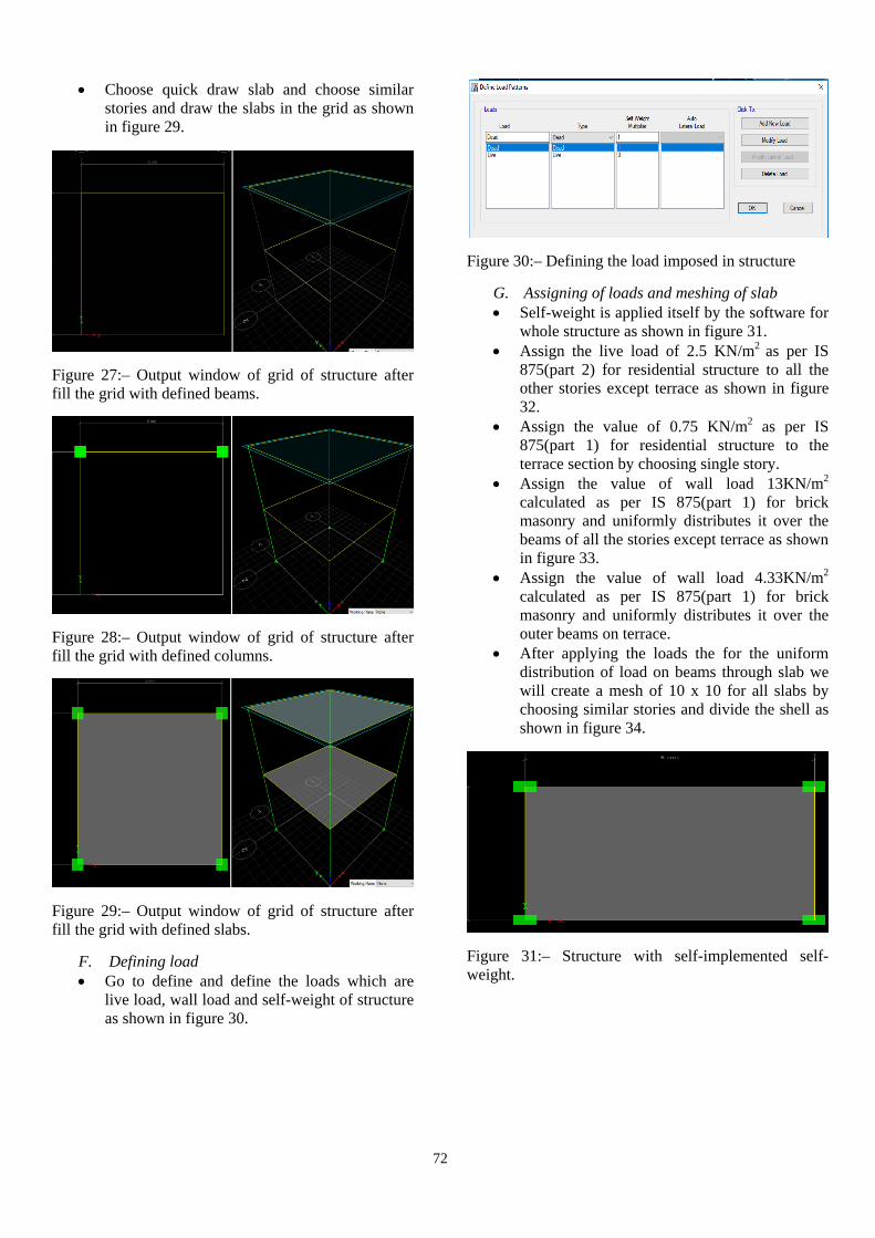
E. Fill the grid with defined members • We will choose quick draw beam icon and
select similar stories and draw the beam in the grid as shown in figure 27.
• Choose quick draw column base story choose column of dimension .5m x .5m and click on the column places and for other stories use .4m x .4m as shown in figure 28.
72
• Choose quick draw slab and choose similar stories and draw the slabs in the grid as shown in figure 29.
Figure 27:– Output window of grid of structure after fill the grid with defined beams.
Figure 28:– Output window of grid of structure after fill the grid with defined columns.
Figure 29:– Output window of grid of structure after fill the grid with defined slabs.
F. Defining load • Go to define and define the loads which are
live load, wall load and self-weight of structure as shown in figure 30.
Figure 30:– Defining the load imposed in structure
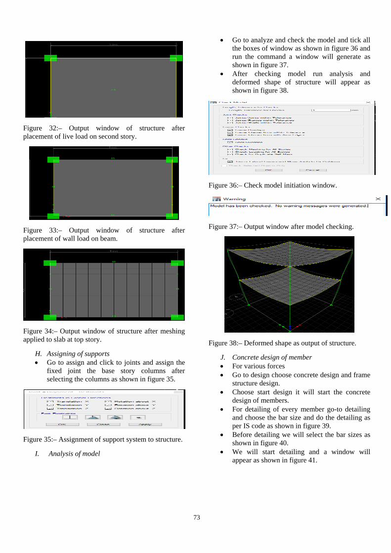
G. Assigning of loads and meshing of slab • Self-weight is applied itself by the software for
whole structure as shown in figure 31. • Assign the live load of 2.5 KN/m2 as per IS
875(part 2) for residential structure to all the other stories except terrace as shown in figure 32.
• Assign the value of 0.75 KN/m2 as per IS 875(part 1) for residential structure to the terrace section by choosing single story.
• Assign the value of wall load 13KN/m2 calculated as per IS 875(part 1) for brick masonry and uniformly distributes it over the beams of all the stories except terrace as shown in figure 33.
• Assign the value of wall load 4.33KN/m2 calculated as per IS 875(part 1) for brick masonry and uniformly distributes it over the outer beams on terrace.
• After applying the loads the for the uniform distribution of load on beams through slab we will create a mesh of 10 x 10 for all slabs by choosing similar stories and divide the shell as shown in figure 34.
Figure 31:– Structure with self-implemented self-weight.
73
Figure 32:– Output window of structure after placement of live load on second story.
Figure 33:– Output window of structure after placement of wall load on beam.
Figure 34:– Output window of structure after meshing applied to slab at top story.
H. Assigning of supports • Go to assign and click to joints and assign the
fixed joint the base story columns after selecting the columns as shown in figure 35.
Figure 35:– Assignment of support system to structure.
I. Analysis of model
• Go to analyze and check the model and tick all the boxes of window as shown in figure 36 and run the command a window will generate as shown in figure 37.
• After checking model run analysis and deformed shape of structure will appear as shown in figure 38.
Figure 36:– Check model initiation window.
Figure 37:– Output window after model checking.
Figure 38:– Deformed shape as output of structure.
J. Concrete design of member • For various forces • Go to design choose concrete design and frame
structure design. • Choose start design it will start the concrete
design of members. • For detailing of every member go-to detailing
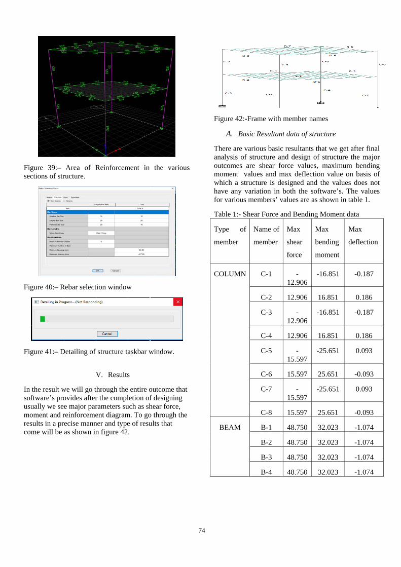
and choose the bar size and do the detailing as per IS code as shown in figure 39.
• Before detailing we will select the bar sizes as shown in figure 40.
• We will start detailing and a window will appear as shown in figure 41.
74
Figure 39:– Area of Reinforcement in the various sections of structure.
Figure 40:– Rebar selection window
Figure 41:– Detailing of structure taskbar window.
V. Results
In the result we will go through the entire outcome that software’s provides after the completion of designing usually we see major parameters such as shear force, moment and reinforcement diagram. To go through the results in a precise manner and type of results that come will be as shown in figure 42.
Figure 42:-Frame with member names
A. Basic Resultant data of structure
There are various basic resultants that we get after final analysis of structure and design of structure the major outcomes are shear force values, maximum bending moment values and max deflection value on basis of which a structure is designed and the values does not have any variation in both the software’s. The values for various members’ values are as shown in table 1.
Table 1:- Shear Force and Bending Moment data
Type of
member
Name of
member
Max
shear
force
Max
bending
moment
Max
deflection
COLUMN C-1 -12.906
-16.851 -0.187
C-2 12.906 16.851 0.186
C-3 -12.906
-16.851 -0.187
C-4 12.906 16.851 0.186
C-5 -15.597
-25.651 0.093
C-6 15.597 25.651 -0.093
C-7 -15.597
-25.651 0.093
C-8 15.597 25.651 -0.093
BEAM B-1 48.750 32.023 -1.074
B-2 48.750 32.023 -1.074
B-3 48.750 32.023 -1.074
B-4 48.750 32.023 -1.074
75
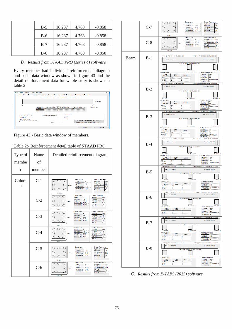
B-5 16.237 4.768 -0.858
B-6 16.237 4.768 -0.858
B-7 16.237 4.768 -0.858
B-8 16.237 4.768 -0.858
B. Results from STAAD PRO (series 4) software
Every member had individual reinforcement diagram and basic data window as shown in figure 43 and the detail reinforcement data for whole story is shown in table 2
Figure 43:- Basic data window of members.
Table 2:- Reinforcement detail table of STAAD PRO
Type of
membe
r
Name
of
member
Detailed reinforcement diagram
Column
C-1
C-2
C-3
C-4
C-5
C-6
C-7
C-8
Beam B-1
B-2
B-3
B-4
B-5
B-6
B-7
B-8
C. Results from E-TABS (2015) software
76
For interpretation of results in E-TABS (2015) we will divide the following results as per defined members such as columns, beams and slabs. Results will be discussed as per how to interpret for every member.
For column we have the concrete column schedule table as shown in figure 44 detail of reinforcement or cage drawing is shown in figure 45 and sectional view of column is shown in figure 46 and gives the inner detail of column.
Similarly for beam we have the reinforcement rebar table as shown in figure 48 cage diagram which is subdivided in zone A, B and C is shown in figure 47 and sectional view of cage of beam is as shown in figure 49.
Figure 44:- Concrete Column Schedule
Figure 45:- Cage Diagram of Column
Figure 46:- Sectional View of Column
Figure 47:- Cage Diagram of Column
Figure 48:- Concrete Beam Rebar Table.
Figure 49:- Sectional View of Beam
VI. CONCLUSION
If we go through results of G+1 RCC frame structure design we will be able to see that when we see the detailed reinforced diagram. In STAAD PRO we see that we can access a detailed diagram by clicking right on the member and all the specification such as shear force, moment, deflection and detailed reinforcement diagram can be seen. In E-TAB when we proceed with detailing the detailed report can be seen and all the columns
77
and beams detailed reinforced diagram is shown with junctions and joints. E-TAB is having an advantage in resultant reinforced diagrams over STAAD PRO. For example when we see the moment and shear force values are similar in both the software because the value of loading is similar. But when we see the detailed reinforced output there are some significant changes for example if we see our design structure none of the members in the STAAD PRO has been corrected by software itself but in E-TAB the software corrects the structure by changing parameters as per requirement it makes the structure economical by removing unwanted members such as beam and column. The reinforcement is not changing in STAAD PRO the diameter and shape of column and beam bars is altered in E-TAB for example bar placements of beams are in every story on the basis of its sectional view from second story onwards as well as longitudinal bar diameter is changed from 14 mm to 12 mm from second story onwards. In E-TAB itself similarly beams reinforcement is also changed to counter act load as per economical designs to get unaltered design we have to give a large amount of data but to make software work by itself we haven’t provided detailed data for design. So from the result output we consider that E-TAB provides better results than STAAD PRO.
VII. REFERENCES [1] IS-875-1987."Indian standard code of practice for
structural safety loadings standards” Part-1, 2 Bureau of Indian Standards, New Delhi
[2] IS-456-2000 "Indian standard of code and practice for plain and reinforced concrete" Bureau of Indian Standards, New Delhi -2
[3] Structural Design of concrete structure using E-Tabs, ShivamAsawa, IOSR Journal of Mechanical and Civil Engineering (IOSR-JMCE) Volume 14, Issue 1 ver. 4 (Jan – Feb 2017), PP 49-51
[4] P. Prashanth, S. Anshuman, R.K. Pandey, Herbert Arpan, “Comparison of design results of a Structure designed using STAAD and ETABS Software,” INTERNATIONAL JOURNAL OF CIVIL AND STRUCTURAL ENGINEERING, Volume 2, No 3, 2012
[5] Design and analysis of multi-storeyed building under static and dynamic loading conditions by using E-TABS by Balaji and Selvarasan in International Journal of Technical Research and Applications, Volume 4 , Issue 4(July-Aug, 2016), PP.1-5
[6] Chandrashekarand and Rajashekar (2015), “Analysis and Design of Multi Storied Building by
Using ETABS Software”, International journals of scientific and research vol.4: issue.7: ISSN no. 2277-8179
[7] Geethu S N, Depthi M, Abdul Nasir N A and Izzudeen K M(2016) Comparative study on design and analysis of multi storied building by STAAD.Pro and ETABS softwares