3 Asst. Professor, Civil Engg., SSE Mangalore (India) ---------------------------------------------------------------------***---------------------------------------------------------------------
Abstract - In this study, seismic analysis of multistory reinforced concrete structure has been carried out by considering two types of floor diaphragm. The floor diaphragm means the interaction of the lateral load with lateral load resisting vertical elements is achieved by the use of floor system. For the analysis E-tabs software has been used, the analysis was carried out in structure with two different floor diaphragm, that is rigid floor diaphragm and flexible floor diaphragm. And this comparative study is done with two different type of structures, that is structure without shear wall and structure with shear wall and the results are collected in terms of Maximum storey displacement, Maximum storey drifts, Storey Shear, and Storey Stiffness for Z-II and Z-V.
Index Terms – Rigid diaphragm, flexible diaphragm, analysis using E-Tabs, storey displacement, storey drift, storey stiffness, storey shear.
1. INTRODUCTION: Diaphragm implies the interaction of the lateral load with lateral-force-resisting vertical components is accomplished by the utilization of floor frameworks that for the most part have substantial in-plane stiffness. Thus, the aggregate horizontal load resistance includes the vertical load resisting components in extent to their particular stiffness. Floors can go about as diaphragm as a result of its huge in-plane stiffness. Transmitting the inertial forces generated by the ground movement of floor mass at an level offered to horizontal force resisting vertical components produced by ground movement is the main capacity of the floor diaphragm. At bring down story, huge lateral load should be exchanged starting with one component then onto the next component causing noteworthy shear forces and bending moments in the diaphragm.
2. DIFFERENT TYPES OF DIAPHRAGM:
2.1 RIGID DIAPHRAGM: When the diaphragm is at midpoint displacement then it is considered as Rigid under lateral load and it is less than twice the average displacements at its ends. It also distributes the lateral forces to the vertical elements in direct proportion to the relative rigidities. It is based on the assumption that the each vertical will cause some deflection some amount and diaphragm does not deform itself. It will also transfer torsional, shear deflections and also forces based on the assumption, that the diaphragm and this will produce additional shear force in the shear wall that undergoes rigid body rotation.
2.2 SEMI-RIGID DIAPHRAGM: For the analysis the assumptions made that the semi-rigid diaphragm can be made as to a diaphragm's rigidity or flexibility because the diaphragm is neither perfectly rigid nor perfectly flexible, but in some cases the diaphragm deflection and the vertical lateral load-resisting elements can be of same magnitude only in semi-rigid diaphragm.
2.3 FLEXIBLE DIAPHRAGM: Diaphragms are considered as flexible when the midpoint displacement, under lateral load, exceeds twice the average displacement of the end supports and also when the maximum lateral deformation of the diaphragm is more than two times and the average story drift of the associated story. It may be determined by comparing the computed midpoint in-plane deflection of the diaphragm itself under lateral load with the drift to adjoining vertical elements under tributary lateral load.
3. PROBLEM MODELING:
Table 1: Structural details
SL. No.
Description Details
01 Total height of
building 90.5 m
02 No. of stories 30
03 Height of each
storey 3.0 m
04 Height of
ground storey 3.5 m
05 Grade of concrete
M30 for beams and columns M25 for slab
05 Grade of steel Fe500 06 Depth of slab 125 mm
07 Size of beams
300 x 500 mm upto 10stories
250 x 400 mm 11-20 stories
200 x 350 mm 21- 30 stories
08 Size of
columns
700 x 700 mm upto10 stories
600x 600 mm 11-20 stories
500 x 500 mm 21-30 stories
09 Codes
IS 456:2000,
IS 875-1987 (Part II) - Live Loads/ Design Loads,
IS 875 (Part III): 1987 - For Wind oads
IS 1893 (Part 1): 2002 – For Earthquake designing
International Research Journal of Engineering and Technology (IRJET) e-ISSN: 2395-0056
4. MODELING OF STRUCTURE: The modeling of the structure was carried out in two cases for Zone-II and Zone-V with consideration of Rigid and Flexible diaphragm.
Case 1: RC Framed Structures
Case 2: Shear-wall structures
Fig.1: Extrude plan and 3D-view of structure
Fig.2: Extrude plan and 3D-view of shear wall structure (X-direction)
Fig.3: Extrude plan and 3D-view of shear wall structure (Y-direction)
5. RESULTS AND DISCUSSION: 5.1 RESLTS FOR DISPLACEMENT: Table 3: Displacement values for Z-II in X and Y directions
STOREY DISPLACEMENT VALUES FOR Z-II
MODEL
SPEC-X SPEC-Y
RIGID FLEXIBLE RIGID FLEXIBLE
FRAMED STRUCTURE
132.209 94.021 119.809 84.815
SHEAR WALLS IN X-DIRECTION
8.947 8.657 113.723 80.378
SHEAR WALLS IN Y-DIRECTION
126.519 90.08 12.714 13.738
Fig. 4: Displacement comparison for Z-II
International Research Journal of Engineering and Technology (IRJET) e-ISSN: 2395-0056
Table 4: Displacement values for Z-V in X and Y directions
STOREY DISPLACEMENT VALUES FOR Z-V
MODEL SPEC-X SPEC-Y
RIGID FLEXIBLE RIGID FLEXIBLE FRAMED
STRUCTURE 475.951 338.453 431.312 305.318
SHEAR WALLS IN X-
DIRECTION
32.21 31.165 409.401 289.36
SHEAR WALLS IN Y-
DIRECTION
455.486 324.288 45.772 49.457
Fig. 5: Displacement comparison for Z-V
5. Discussion on Displacement Values
For the framed structures the displacement in both directions reduced for flexible diaphragm as compared to rigid diaphragm. The displacement at 30th floor for both SPEC-X and SPEC-Y values for flexible diaphragm models, it is 30% less than the rigid diaphragm models.
For the models with shear walls in X-direction in both Z-II and Z-V, The displacement at 30th floor for both SPEC-X and SPEC-Y values for flexible diaphragm models, it is 3.5% and 29% less than the rigid diaphragm model respectively. And the structures in which the shear walls are placed in Y-direction in both Z-II and Z-V, the displacement at 30th floor for SPEC-X and SPEC-Y values for flexible diaphragm models it is 29% and 7.5% less than the rigid diaphragm models.
Table 5: Drift values for Z-II in X and Y directions
STOREY DRIFT VALUES FOR Z-II
MODEL SPEC-X SPEC-Y
RIGID FLEXIBLE RIGID FLEXIBLE
FRAMED STRUCTURE
0.000666 0.000385 0.000632 0.000375
SHEAR WALLS IN X-DIRECTION
0.000121 0.000115 0.000567 0.000312
SHEAR WALLS IN Y-DIRECTION
0.000653 0.000348 0.000185 0.000196
Fig. 6: Drift comparison for Z-II
Table 6: Drift values for Z-V in X and Y directions
STOREY DRIFT VALUES FOR Z-V
MODEL
SPEC-X SPEC-Y
RIGID FLEXIBLE RIGID FLEXIBLE
FRAMED STRUCTURE
0.002399 0.001376 0.002277 0.001342
SHEAR WALLS IN X-
DIRECTION
0.000436 0.000416 0.00204 0.00124
SHEAR WALLS IN Y-
DIRECTION
0.002349 0.001252 0.000664 0.000707
Fig. 7: Drift comparison for Z-V
6. Discussion on Drift Values In framed structures it reaches the highest value in the middle portion of the building that is 14th and 22nd floor in both directions for both Z-II and Z-V. The drift values at 30th floor for both SPEC-X and SPEC-Y values for flexible diaphragm models, it is 42% and 41% less than the rigid diaphragm models respectively.
International Research Journal of Engineering and Technology (IRJET) e-ISSN: 2395-0056
In case of shear wall structures where as shear walls are placed in X-direction the drift values at SPEC-X are gradually increases upto 24th floor and above that the values are decreased gradually, For those models in both Z-II and Z-V, The drift vale at 30th floor for both SPEC-X and SPEC-Y values for flexible diaphragm models, it is 5% and 45% less than the rigid diaphragm model respectively. In another case shear walls are placed in Y-direction the values for SPEC-Y are gradually increases upto 25th floor and after that it is decreased, And the structures in which the shear walls are placed in Y direction in both Z-II and Z-V, the drift at 30th floor for SPEC-X and SPEC-Y values for flexible diaphragm models it is 46% and 6% less than the rigid diaphragm models. Table 7: storey stiffness values for Z-II in X and Y directions
STOREY STIFFNESS VALUES FOR Z-II MODEL
SPEC-X SPEC-Y
RIGID FLEXIBLE RIGID FLEXIBLE FRAMED STRUCTURE
102224.183 176081.176 90421.296 151502.182
SHEAR WALLS IN X-DIRECTION
481326.345 501339.656 123127.2 210513.8
SHEAR WALLS IN Y-DIRECTION
132455.528 228829.244 305282.316
284918.728
Fig. 8: storey stiffness comparison for Z-II
Fig. 9: storey stiffness comparison for Z-V
Table 8: storey stiffness values for Z-V in X and Y directions
STOREY STIFFNESS VALUES FOR Z-V
MODEL
SPEC-X SPEC-Y
RIGID FLEXIBLE RIGID FLEXIBLE FRAMED STRUCTURE
102224.183 176396.004 90421.296 151708.87
SHEAR WALLS IN X-DIRECTION
481326.345 501339.656 123127.202
210513.792
SHEAR WALLS IN Y-DIRECTION
132455.528 228829.244 305282.3 284918.7
7. Discussion on Stiffness Values: In framed structures it reaches the highest value in the ground floor of the building that is 1st floor in both directions for both Z-II and Z-V. The stiffness values at 30th floor for both SPEC-X and SPEC-Y values for flexible diaphragm models, it is 42% and 40% more than the rigid diaphragm models respectively.
In case of shear wall structures for those models in both Z-II and Z-V, The stiffness value at 30th floor for both SPEC-X and SPEC-Y values for flexible diaphragm models, it is 4% and 42% more than the rigid diaphragm model respectively. And the structures in which the shear walls are placed in Y-direction in both Z-II and Z-V, the stiffness value at 30th floor for SPEC-X and SPEC-Y values for flexible diaphragm models it is 42% and 7% more than the rigid diaphragm models. Table 9: storey shear values for Z-II in X and Y directions
STOREY SHEAR VALUES FOR Z-II
MODEL
SPEC-X SPEC-Y
RIGID FLEXIBLE RIGID FLEXIBLE
FRAMED STRUCTURE
204.360 202.321 171.573 169.7133
SHEAR WALLS IN X-DIRECTION
174.724 173.618 209.361 197.177
SHEAR WALLS IN Y-DIRECTION
259.293 238.768 169.027 167.885
Fig. 10: storey shear comparison for Z-II
International Research Journal of Engineering and Technology (IRJET) e-ISSN: 2395-0056
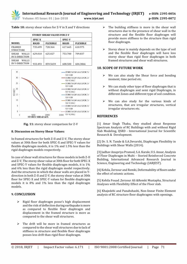
Table 10: storey shear values for Z-V in X and Y directions
STOREY SHEAR VALUES FOR Z-V
MODEL
SPEC-X SPEC-Y
RIGID FLEXIBLE RIGID FLEXIBLE
FRAMED STRUCTURE
735.699 728.364 617.665 610.975
SHEAR WALLS IN X-DIRECTION
629.010 625.027 753.700 709.837
SHEAR WALLS IN Y-DIRECTION
933.493
859.5659
608.500
604.3866
Fig. 11: storey shear comparison for Z-V 8. Discussion on Storey Shear Values: In framed structures for both Z-II and Z-V, The storey shear values at 30th floor for both SPEC-X and SPEC-Y values for flexible diaphragm models, it is 1% and 1.5% less than the rigid diaphragm models respectively. In case of shear wall structures for those models in both Z-II and Z-V, The storey shear value at 30th floor for both SPEC-X and SPEC-Y values for flexible diaphragm models, it is 1% and 6% less than the rigid diaphragm model respectively. And the structures in which the shear walls are placed in Y-direction in both Z-II and Z-V, the storey shear value at 30th floor for SPEC-X and SPEC-Y values for flexible diaphragm models it is 8% and 1% less than the rigid diaphragm models.
9. CONCLUSION
Rigid floor diaphragm posse’s high displacement and the risk of deflection during earthquake is more as compared to flexible floor diaphragm and displacement in the framed structure is more as compared to the shear wall structures.
The drift will be more in framed structures as compared to the shear wall structures due to lack of stiffness in structure and flexible floor diaphragm posses less drift than rigid floor diaphragm.
The building stiffness is more in the shear wall structures due to the presence of shear wall in the structure and the flexible floor diaphragm will provide more stiffness to the structure than rigid floor diaphragm.
Storey shear is mainly depends on the type of soil and the flexible floor diaphragm will have less storey shear than rigid floor diaphragm in both framed structures and shear wall structures.
10. SCOPE OF FUTURE WORK
We can also study the Shear force and bending moment, time period etc.
We can study other type of floor diaphragm that is without diaphragm and semi rigid Diaphragm, in different Zones and different type of soil condition.
We can also study for the various kinds of structures, that are irregular structures, vertical irregular structures etc.
REFERENCES [1] Amar Singh Thaku, they studied about Response Spectrum Analysis of RC Buildings with and without Rigid Slab Modeling, IJSRD - International Journal for Scientific Research & Development.
[2] Dr. S. N. Tande & S.A.Devarshi, Diaphragm Flexibility in Buildings with Shear Walls (2014).
[3] Jadhav Anupriya Pramod, S.A. Karale, U.S. Ansar, Analysis of Floor Diaphragm in Multi – Storied Reinforced Concrete Building, International Advanced Research Journal in Science, Engineering and Technology (IARJEST).
[4] Kehila, Zerzour and Remki, Deformability of floors under the effect of seismic actions.
[5] Kehila Fouad ,Zerzour Ali &Remki Mustapha, Structural Analyses with Flexibility Effect of the Floor slab.
[6] Khajedehi and Panahshashi, Non-linear Finite Element analysis of RC structure floor diaphragms with openings.


![Rigid , Semi Rigid & Flexible Ducting - Holyoakeattachments.holyoake.com/products/files/Spiro-Set[1172].pdf · Rigid , Semi Rigid & Flexible Ducting ... Pressure Drop Per Metre Length](https://static.documents.pub/doc/80x56/5a9e3c667f8b9a36788d1100/rigid-semi-rigid-flexible-ducting-1172pdfrigid-semi-rigid-flexible-ducting.jpg)


