Comparative study of zirconia-mullite and alumina-zirconia composites
N C BISWAS and S P C HA U D HURI* Special Ceramics Section, Central Glass and Ceramic Research Institute, Calcutta 700 032, India
MS received 28 May 1998
Abstract. Several zirconia-mullite and alumina-zirconia composites were prepared and their physical, chemical, mechanical and thermal properties determined. The phase assemblage, size of ZrO 2 crystals and microstructure of the composites were ascertained. This paper embodies a comparison of the alumina-zirconia and zirconia-mullite composites with respect to their properties and also the constitution-property relationships between each group of composites. Alumina-zirconia composites (AZ) were found to be superior to zirconia-mullite composites (prepared through ZMS or ZMC route) in almost all respects. Thermal-shock resistance and hydration resistance of the clay-based zirconia-mullite (ZMC) composites and alumina-zirconia (AZ) composites were almost at par.
Keywords. Composites; zirconia-mulfite; alumina-zirconia; thermomechanical and chemical properties; constitution.
1. Introduction
Zirconia-mullite composites are important structural ceramic materials and specially meant for glass tank furnaces (Asokan 1994). These composites have better corrosion resistance, strength and toughness than mullite alone (Rundgren et al 1988; Claussen and John 1980). Alumina-zirconia composites are promising candidates for application requiring high strength, toughness, wear resistance and thermal-shock resistance (Orange et al
1988; Hwang et al 1994). Typical applications are cutting tools and rocket nozzles (Garvie 1983; Grigorev et al
1991; Arul Dhas and Patil 1994). Zirconia, the dispersed phase in zirconia-mullite or
alumina-zirconia composites, is responsible for (i) grain growth inhibition (Lange and Hirtinger 1987; Hori et al
1988; Endo et al 1994), (ii) stress-induced transforma- tion-related toughening and microcracking toughening, (iii) modification of thermal expansion coefficient (Yuan and Yen 1992) and (iv) modulus of elasticity (Tsukuma and Takahata 1987). These composites have better thermal-shock resistance than the matrix material, i.e. mullite or alumina (Orlova et al 1981; Esper et al 1984).
On the other hand, the hydration resistance of ZrO 2 is improved by the incorporation of mullite or alumina in these composites (Hirano and Inada 1990; Hirano 1992).
Various routes of preparation of these composites were explored and practised by the investigators. These include:
*Author for correspondence
(i) mixing of the components, mullite and zirconia or alumina and sintering the mixture, (ii) reaction sintering of zircon and alumina (Koyama et al 1994), (iii) sol-gel technique (Rundgren et al 1988; Den Exter et al 1989), (iv) coprecipitation method (Kubota and Takagi 1988; Lee and Hong 1994), (v) hydrothermal synthesis (Arul Dhas and Patil 1994), (vi) fusion casting process (Asokan 1994), hot pressing; hot isostatic pressing and (vii) via precursors (Zografou et al 1986; Stead et al
1991). Hot pressing ensured higher density, better micro-
structure, higher strength and toughness (DiRupo et al
1979; Leriche et al 1988; Hirano and Inada 1991). Different additives (Srikrishna et al 1988; Zangvil et al
1992), e.g. Y203, MgO, CaO, TiO 2, La203, Nh205, CeO 2 were employed to stabilize the tetragonal ZrO 2 phase. Microstructure of the composites is sensitive ta the processing parameters. Normal pressing usually generated porous microstructure.
In the present investigation, zirconia-mullite composites were obtained by in situ reaction sintering of (i) zircon sand and alumina mixtures (ZMS) and (ii) clay-atumina- zirconia mixtures (ZMC). Alumina-zirconia composites were obtained from calcined technical alumina and mono- clinic zirconia mixtures (AZ). Various sintering additives such as Y203 , CeO2, ZrO 2 were employed to stabilize the tetragonal ZrO 2 phase.
Densification of these composites by normal pressure sintering was ascertained. The concentrations of the phases were estimated by X-ray diffractometry as well as the size of the ZrO 2 crystals in these composites.
37
38 N C Biswas and S P Chaudhuri
The microstructures of these composites were revealed by scanning electron microscopy• The strength, fracture toughness, Young's modulus, thermal-shock resistance, hydration resistance, corrosion resistance by molten iron and borosilicate and soda-lime silicate glass of these composites were also investigated. The properties of these composites were then compared on the basis of their phase compositions and microstructures.
2. Experimental
2.1 Raw materials and sample preparation
The raw materials used in this investigation were technical alumina, monoclinic zirconia, zircon sand (zirconium silicate) and Rajmahal china clay.
The chemical analysis of the raw materials were con- ducted by the standard methods of wet chemical analysis (figure 1).
The batch for each composite was wet ground for 30h in porcelain jars with alumina balls and the slip was sieved and dried. The dried mass was pressed at 650 kg/cm 2 and also at 3,165 kg/cm 2 to bars of dimen- sions, 7 8 x 1 8 × 4 - 5 r n m 3 in isostatic press. Crucibles were fabricated by suspension casting in plaster of Paris moulds. The samples were fired in oil-fired furnace with saggers between 1465°C and 1650°C, depending on the composition of the composite, with a soaking period of 1.5 h at the peak temperature. Besides, all the compo- sites were allowed an intermediate soaking for 0.5 h at 1400°C.
2.2 Measurement of properties
Bulk density was measured by the water displacement method. Water absorption was also measured.
Flexural strength in three-point bending and Young's modulus were determined with the help of Instron machine (model 1195):
3 WL Flexural strength = (1)
2 bd 2'
w/3 Young's modulus = 4--816' (2)
A × 2 x Cross head speed 6 = deflection ±
Chart speed
Here, W is the breaking load, L the span length, 5 cm, b the width, d the thickness and I the moment of inertia = bd3/12, w the load corresponding to chart loading A in the load-displacement curve, cross head speed = 0.5 mm/min and chart speed = 100 mm/min.
Fracture toughness was measured by three-point bend- ing of notched specimens.
Fracture toughness, K~c- Y3Pl
2bw '2 - _ _ . ~ MNm -3/2,
where P is the breaking load, l the bearing spacing or span length, a, the notch depth in mm, b the sample width, w" the sample height with notch at the bottom
- I
2O
0 ~
I00 I0 I
' ° ° r 8O
fO
W
40
$ ~2
t013
LQtWkLENT ~ IX,UIEI'ER, ( ,urn l
~ ~ ZIRCON SAND, 50 hrs. ground Av. particle size
I I I I I I
30 I0 5 3 2 i 0.5
(B)
EQUIVALENT .~,;HERICAL DIA./4m
iO0 (C)
I00 I0 i
E~NJ~rr g ~ n t ~ , ! jura)
Figure 1. (A--C) The particle size-distribution of powdered raw materials are shown.
Zirconia-mullite and alumina-zirconia--A comparative study 39
side and Y= a geometric factor, = 1-93 - 3-07 (a/w') + 13.66 (a/w') 2 - 22.98 ( a / w ' ) 3 + 25.22 (a/w') 4. At least four samples were tested for each composition.
Repeated thermal-shock cycling of bars from 1200°C to ambient temperature and determination of their strength after 0, 3, 5, 10, 15, 20 cycles were carried out. In addition to the above tests, bar samples were subjected to hydration in steam in an autoclave at 170°C under a pressure of 7 kg/cm 2. The autoclaved samples were visually examined, ground to 200 mesh (BSS) and studied by infrared spectroscopy.
The crucibles were subjected to corrosion test by the agents, e.g. Corning borosilicate glass at 1450°C for 2 h, soda-lime silicate glass at 1450°C for 2 h and iron + 8% red lead mixture at 1500°C for 0.5 h. The crucibles that survived were then sectioned by diamond wheel for observation.
2.3 Phase concentration and microstructure
Concentration of crystalline phases were estimated by X-ray diffractometry (Klug and Alexander 1954) using
1.4
1.2
0.6 Z
e"
5r ¢-.
1,0
0.8
0.4
0.2
0 i I a I I I l
0 20 40 60 MULLITE( W T.*/*)
Figure 2. X-ray calibration curve for mullite.
I
sodium fluoride as internal standard. The X-ray calibration curves for mullite, corundum, m-ZrO 2 and t-ZrO 2 as shown in figures 2-5, were prepared by plotting the known concentration of each pure phase against the ratio of peak heights of the pure phase and the internal standard. The concentration of the phase in the sample was then computed from the calibration curve by comparing the ratio of the peak heights of the phase in the sample and the internal standard.
U . 0
#2 ,...,.,.
0 0
I I I I I I I |
10 20 30 40 50 60 70 CORUNDUM (wr. %)
Figure 3. X-ray calibration curve for corundum.
6
5
4 b_ O Z £
3 ? N
!
E z: 2
0 0
Figure 4.
i I | i i i I I i
10 20 30 40
m_ ZrO 2 ( W T.°Io)
X-ray calibration curve for m-ZrO 2.
I
5O
40 N C Biswas and S P Chaudhuri
Size of m-ZrO 2 and t-ZrO 2 crystals was measured by the X-ray line broadening technique (Jones 1938) employing quartz as internal standard.
0.92 Crystal size Dhkl = P l / 2 C O S 0 '
where 2 is the wave length of the X-ray beam, fll/2 the pure diffraction broadening of the peak at half the height and 0 the glancing angle of the selected reflection.
Microstructures of HF etched, fractured as well as polished surfaces of the composites were unveiled by the scanning electron microscope.
3. Results
The chemical analyses of the raw materials and the batch compositions of the composites are reported in tables 1 and 2, respectively. The phase compositions of sintered samples as determined by X-ray analysis are presented in table 3. Sizes of ZrO 2 crystals are shown in table 4. Properties of the composites such as flexural strength, water absorption, bulk density, fracture toughness, Vickers microhardness and Young's modulus are compiled in table 5. Resistance to thermal-shock and corrosion by glass and iron as well as hydration behaviour of the composites are recorded in table 6.
4. Discussion
4.1 Constitution
4.1a Phase composition: Addition of Y203 helped retention of t-ZrO 2 in AZ and ZMS composites (table 3) at room temperature. Only m-ZrO 2 was detected in ZMC samples.
3£)
2.5
2.0
0
.~1.5
N
' a.0 ¢..
0.5
Figure 5.
Unreacted AI203 was observed in the ZMS and in most of the ZMC samples. The presence of excess alumina in stoichiometric ZMS composition indicated incomplete reaction between tx-Al203 and cristobalite originated by the decomposition of zircon. ZMS5 con- tained strong flux like cryolite, resulting in formation of large amount of glassy phase. Mullite could not be detected in ZMS5 for this reason. The estimated amount of ZrO 2 was also very small in ZMS5.
The effect of annealing on the crystalline phases was most prominent in the ZMS composites (Mitra et al 1989a, b). Annealing enhanced the growth of crypto- crystalline mullite as well as origin of the t-ZrO 2 phase in the ZMS samples.
4 . tb Microstructure: A few representative SEM micro- graphs of the composites are exhibited in figures 6A, B, C to show the difference in their microstructure.
The ZrO z grains were distinctly visible as round bright phase within the A1203 grains in the micrograph of AZ4 (figure 6A). The ZrO 2 grains were also distinguishable in the micrograph of ZMC (figure 6B) and ZMS (figure 6C). The low contrast in this case was due to lower A1-Si/Zr atomic absorption coefficient compared to that of A1/Zr.
Acicular and hexagonal mullite grains were present in ZMC2, ZMC3 composites in figures 7A and 7B, respec- tively. Mullite grains were irregular shaped, hexagonal and faceted in the ZMS samples (figure 7C).
Alumina grains in AZ samples were hexagonal and irregular shaped (figure 7D).
The fractographs (figures 8A and B) revealed the existence of pores (closed, open and blocked) in the microstructure of all the composites. However, ZMS samples (figure 8A) were more porous than the ZMC samples (figure 8B). This exactly matched the bulk densities of ZMS samples that were less than that of ZMC samples.
The formation o f ZMS and Z M C compos i tes invo lved
reaction fol lowed by sintering or in situ react ion sinter-
ing. The reaction was initiated in Z M S by the decom-
posi t ion o f zircon sand grains into ZrO 2 part icles o f
submicron order and amorphous SiO 2. This was fo l lowed
by the formation of cryptocrystal l ine mul l i te and crys-
tall ization o f extremely fine mull i te and z i rconia grains
which finally sintered (Mitra et al 1985). The clay
component in ZMC suffered dehydroxyla t ion at the very
outset producing a-A1203 and amorphous S iO 2. In the next step, mull i te crystal l ized and both mul l i te and
zirconia sintered. The sintering o f A Z composi tes
depended on the diffusion-control led mechanism. A sol id
solut ion o f the fol lowing composi t ion fo rmed which was
attended with the creation o f oxygen vacancy, i.e.
Zrl -xYxO2-x/2 [~/2. The highest bulk densities o f the A Z samples were
the direct consequence o f very fast rate o f sintering
through the defect sites (oxygen vacancy) . The higher
bulk densities o f the Z M C samples as compared to those
42 N C Biswas and S P Chaudhuri
of the ZMS samples was most possibly due to much lower temperature where the initial reaction leading to sintering set in. The dehydroxylation of clay in the ZMC group occurred much earlier (~ 600°C) than the decom- position of zircon in the ZMS group (-1450°C).
The size of ZrO 2 crystals was in the very low submicron level for all the ZMS compositions (table 4) except ZMS1 which had 1.06 ktm ZrO 2 crystals. The very fine ZrO 2 crystals (<0.1 pan) in the ZMS composites had their origin in the decomposition of ZrSiO 4 at high temperature ( - 1450°C). Comparatively large size of ZrO 2 crystals (> 0-t I.tm) in all the ZMC compositions and in most of the AZ compositions might be due to the large size of the initial ZrO 2 crystals used in their batches.
4.3 Properties
4.3a Mechanical strength: With respect to modulus of rupture of Young 's modulus, the AZ composites were
found to be superior to the composites of ZMC and ZMS. The AZ group achieved, in general, the highest mechanical strength which was followed by the ZMC and ZMS groups, successively (table 5).
The quantitative phase compositions (table 3) showed that mullite was absent in all the AZ composites but most of the ZMS composites contained more mullite than the ZMC composites. On the other hand the AZ composites were the richest in the corundum content but the concentrations of corundum in the ZMC composites were greater than those in the ZMS composites (table 3). Further, while AZ group of samples were very poor in m-ZrO 2 content, the ZMC and ZMS groups of samples had significant amounts of m-ZrO 2 (table 3). It may be inferred, therefore, that corundum phase was responsible for the attainment of high mechanical strength.
The highest mechanical strength in the AZ group of the samples was also the consequence of the onset of
Table 5. Firing temperature and properties of the composites.
Table 6. Comparison of some thermomechanical and chemical properties of ZMS, ZMC and AZ composites.
ZMS 1 ZMC 1 ZMS2 ZMC2 AZ3
Properties ZMS3 ZMC3 AZ5
Thermal-shock resistance (cycles 6-10 1200°C-R.T. without failure)
Strength after 16 cycles 1200°C to R.T. (kg/cm 2)
Corrosion resistance; (borosilicate glass and No corrosion soda-lime silicate glass at 1450°C, 2 h)
1 (Iron, 1500°C, i h) Eaten away
Hydration in autoclave; 10 h
20 h No crazing
20
750-800
No corrosion
Eaten away
Appearance of 3500cm -I peak in IR spectra
No crazing
20
450-540
No corrosion
Partially corroded
Appearance of 3500 cm -1 peak in IR spectra
No crazing
Zirconia-mullite and alumina-zirconia--A comparative study 43
rapid sintering from low temperature via the defect centres created in ZrO 2 component by the additive Y203 that led to the highest bulk density products among the three groups (tables 2 and 4). T h i s fact was supported by the highest mechanical strength of the ZMC5 sample among the ZMC group which only had Y203 additive in its batch composition in this group and sintered to the highest bulk density. Similarly, in spite of addition of considerable amount of Y203 in almost all the samples of ZMS group, initiation of sintering through defect centres generated in ZrO 2 was not possible at low temperature due to non-availability of ZrO 2 at low temperature which was released in the system only at high temperature (> 1450°C) by the breakdown of ZrSiO 4 contained in their batch compositions. The low bulk density and low mechanical strength of this group may also be assigned to this reason.
Figure 6. SEM micrographs of polished sections of samples, (A) AZ4, (B) ZMC3, (C) ZMS5.
4.3b Fracture toughness: Corundum has a fracture toughness value of 3 MNm -3/2 compared to 2 MNm -3/2 of mullite (Becher 1994). Comparison of fracture tough- ness of AZ and ZMC, ZMS composites had been done with due consideration to the base values of these phases as well as their amount. The size and amount of three polymorphs of ZrO 2 phase were also taken into account.
It appeared from table 3 that the AZ composites had the highest corundum content but had no mullite. The ZMS and ZMC composites contained both corundum and mullite phases but ZMS were more rich in mullite and ZMC were more rich in corundum. The values of fracture toughness of the AZ, ZMS and ZMC groups of composites were well supported by the concentration of mullite and corundum phases in these groups and the base values of fracture toughness of these phases. The highest corundum content (67-83wt%), in spite of absence of mullite, in AZ group was a major cause of their highest fracture toughness. The high concentration of the low fracture toughness phase, i.e. mullite (38- 56 wt%) was coupled with low concentration of high fracture toughness phase, i.e. corundum (15-46 wt%) in the ZMS group. In the ZMC group, on the contrary, low mullite content (15-60wt%) and high corundum content (15-68 wt%) were present. Though the fracture toughness of these two groups should differ considerably, i.e. ZMC group must have higher fracture toughness than the ZMS group, it was found to be very close (table 5). This anomaly may be explained on the basis of their ZrO 2 phase content. The ZMC group contained only small amount of m-ZrO 2 (10-32 wt%) but the ZMS group had m-ZrO 2 (6-34 wt%), t-ZrO 2 (10-24 wt%) and c-ZrO 2 (30 wt%) in ZMS3 only (cf. table 3). The presence of higher amount of ZrO 2, particularly the t-ZrO 2, in the ZMS composites, therefore, improved their fracture toughness to be almost at par with that of ZMC com- posites. The tetragonal ZrO 2 gave rise to transformation
44 N C Biswas and S P Chaudhuri
toughening (TI') in ZMS4 particularly, compared to ZMC1 depending upon microcracking toughening (MT) only.
The tetragonal ZrO 2 in AZ3 and AZ5 samples (each containing 1-5 wt% Y203) contributed to TT. Highest fracture toughness (5-5MNm -3/2) was shown by the sample AZ5, mainly due to moderately high concentration (18.2 wt%) (table 3) and big size (0-22 ~m) (table 4) of transformable t-ZrO 2 in this sample. In AZ1, AZ4 and AZ6 samples containing monoclinic ZrO 2 and cubic ZrO 2 phases, the microcracking toughening (MT) and crack deflection phenomena were operative.
The glassy phase which was produced in the ZMS5 composite due to incorporation of the fluxing agent cryolite (table 2) in it was responsible for low fracture toughness of the composite. Fracture toughness of ZMS 1, 2, 3 composites was not determined because of their high water absorption and low bulk density.
4.3c Hardness: Hardness of AZ composites was better than that of ZMS and ZMC composites (table 5) since hardness of corundum is higher than that of mullite and ZrO 2. Optical polishing was not achieved for ZMS1 owing to its low density and for ZMC2, ZMC3 due to their higher water absorption. So hardness was not measured for these compositions. ZMS2 and ZMS5 showed the lowest hardness because of low density of ZMS2 and presence of glassy phase in ZMS5. The composites ZMS3, ZMS4, ZMC1, AZ1 and AZ4 had hardness values that varied within a narrow range 970- 990 kg/cm 2 in spite of wide difference in their phase compositions and crystal size of ZrO z phases. AZ3, AZ5 and AZ6 had hardness values 1002-1030kg/cm 2 by virtue of their good sintering, microstructure and phase assemblage.
It appears that high degree of sintering is a prerequisite condition for high hardness of a sample. The highest
Figure 7. SEM micrographs of fractured surfaces of samples, (A) ZMC2, (B) ZMC3, (C) ZMS2 and (D) AZ3.
Zirconia-mullite and alumina-zirconia--A comparative study 45
values of hardness of composites AZ3, AZ5 and AZ6 of high bulk density stood as proof.
4.3d Thermal-shock resistance: Thermal-shock resis- tance of ZMC and AZ composites were very good. These composites survived 20cycles (1200°C-R.T.) without failure. The ZMS composites showed poor resistance to thermal-shock (table 6). Microcracks formed on thermal-shock cycling, network of microcracks increased gradually after each cycle and finally micro- fissure formation took place in the material (Mitra et al 1992b; Biswas and Chaudhuri 1997). Even then substan- tial strength was retained by the AZ and ZMC samples (Mitra et al 1992a, b; Biswas and Chaudhuri 1997). ZMS composites did not fail after 6 to 10 cycles, but cracked thereafter (table 6). The ZMS samples were found to be inferior to others in thermal-shock resistance.
Mullite was absent in the AZ composites and present in the ZMC composites in smaller amount than in the ZMS composites. The AZ composites were the richest
but the ZMS composites were poorest in corundum content and ZMC composites had corundum in between. The thermal-shock resistance of the ZMC composites was found to be the best which was followed by the AZ and the ZMS composites, successively (table 6). The ZMC retained strength of 750--800 kg/cm 2 while AZ 450-540kg/cm 2 and ZMS nil after 16cycles (table 6). The highest thermal-shock resistance of the ZMC com- posites was the result of beneficial effect of both mullite and corundum present in considerable amount in this group (table 3). The beneficial effect of the highest quantity of corundum in the absence of the other phase (mullite) in the AZ composites (table 3) placed this group next to the ZMC group. In ZMS, the presence of highest amount of mullite in association with small
Figure 9. SEM micrograph of fractured surface of sample ZMS4.
Figure 8. SEM micrographs of fractured surfaces of samples, Figure 10. SEM micrograph of fractured surface of sample (A) ZMS2 and (B) ZMC1. AZ4 with intragranular ZrO 2 grains.
46 N C Biswas and S P Chaudhuri
resistant to molten glass and, therefore, made the zirconia-mullite (ZMS and ZMC) and alumina-zirconia composite (AZ) immune to it. Molten iron, however, decomposed mullite incongruently to A1203 and SiO 2 and then reacted with SiO 2 to produce low melting compounds, e.g. fayalite (2FeO.SiO 2) and wtistite (FeO-SiO 2) of melting points 1205°C and about 1000°C, respectively. Therefore, ZMS and ZMC composites con- taining mullite were fully corroded by molten iron. On the contrary, molten iron formed high melting (1780°C) compound, e.g. hercynite, (FeO.A1203) by reaction with A1203 in the AZ composite. Therefore, AZ composites containing corundum+zirconia but no mullite were partially corroded.
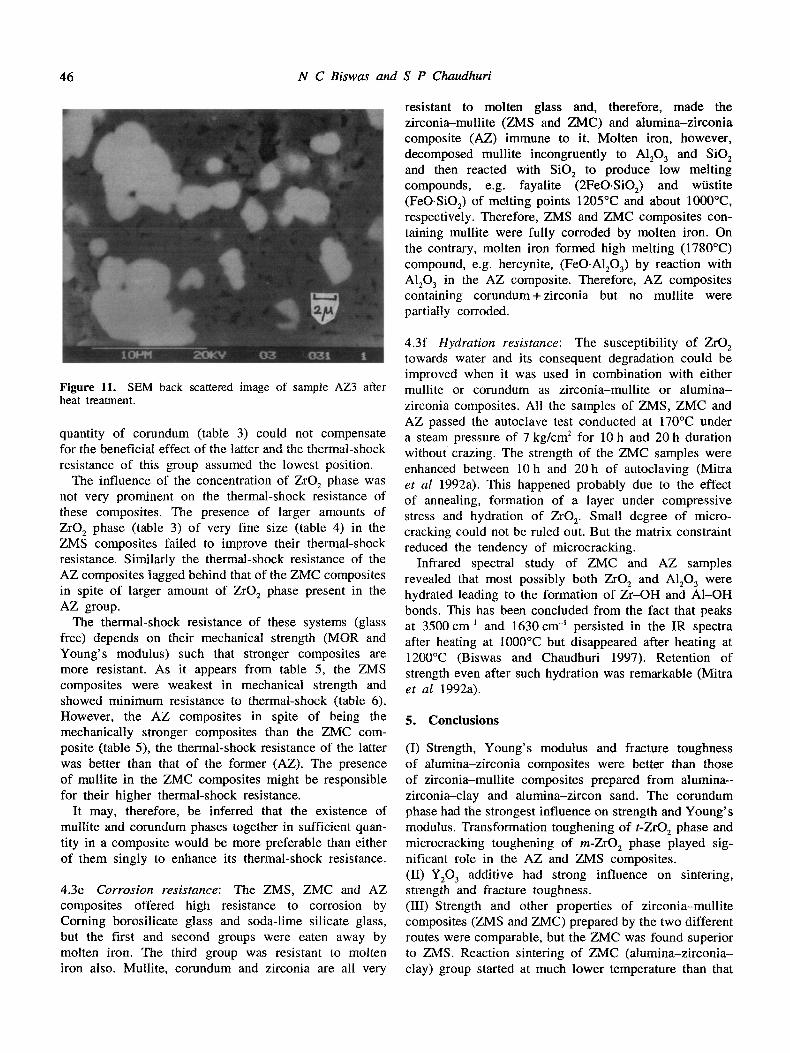
Figure 11. SEM back scattered image of sample AZ3 after heat treatment.
quantity of corundum (table 3) could not compensate for the beneficial effect of the latter and the thermal-shock resistance of this group assumed the lowest position.
The influence of the concentration of ZrO 2 phase was not very prominent on the thermal-shock resistance of these composites. The presence of larger amounts of ZrO 2 phase (table 3) of very fine size (table 4) in the ZMS composites failed to improve their thermal-shock resistance. Similarly the thermal-shock resistance of the AZ composites lagged behind that of the ZMC composites in spite of larger amount of ZrO 2 phase present in the AZ group.
The thermal-shock resistance of these systems (glass free) depends on their mechanical strength (MOR and Young's modulus) such that stronger composites are more resistant. As it appears from table 5, the ZMS composites were weakest in mechanical strength and showed minimum resistance to thermal-shock (table 6). However, the AZ composites in spite of being the mechanically stronger composites than the ZMC com- posite (table 5), the thermal-shock resistance of the latter was better than that of the former (AZ). The presence of mullite in the ZMC composites might be responsible for their higher thermal-shock resistance.
It may, therefore, be inferred that the existence of mullite and corundum phases together in sufficient quan- tity in a composite would be more preferable than either of them singly to enhance its thermal-shock resistance.
4.3e Corrosion resistance: The ZMS, ZMC and AZ composites offered high resistance to corrosion by Corning borosilicate glass and soda-lime silicate glass, but the first and second groups were eaten away by molten iron. The third group was resistant to molten iron also. Mullite, corundum and zirconia are all very
4.3f Hydration resistance: The susceptibility of ZrO 2 towards water and its consequent degradation could be improved when it was used in combination with either mullite or corundum as zirconia-mullite or alumina- zirconia composites. All the samples of ZMS, ZMC and AZ passed the autoclave test conducted at 170°C under a steam pressure of 7 kg/cm 2 for 10 h and 20 h duration without crazing. The strength of the ZMC samples were enhanced between 10 h and 20h of autoclaving (Mitra et al 1992a). This happened probably due to the effect of annealing, formation of a layer under compressive stress and hydration of ZrO 2. Small degree of micro- cracking could not be ruled out. But the matrix constraint reduced the tendency of microcracking.
Infrared spectral study of ZMC and AZ samples revealed that most possibly both ZrO 2 and AI203 were hydrated leading to the formation of Zr-OH and A1-OH bonds. This has been concluded from the fact that peaks at 3500 cm -1 and 1630 crn q persisted in the IR spectra after heating at 1000°C but disappeared after heating at 1200°C (Biswas and Chaudhuri 1997). Retention of strength even after such hydration was remarkable (Mitra et al 1992a).
5. Conclusions
(I) Strength, Young's modulus and fracture toughness of alumina-zirconia composites were better than those of zirconia-mullite composites prepared from alumina- zirconia-clay and alumina-zircon sand. The corundum phase had the strongest influence on strength and Young's modulus. Transformation toughening of t-ZrO 2 phase and microcracking toughening of m-ZrO 2 phase played sig- nificant role in the AZ and ZMS composites. (II) Y203 additive had strong influence on sintering, strength and fracture toughness. (III) Strength and other properties of zirconia-mullite composites (ZMS and ZMC) prepared by the two different routes were comparable, but the ZMC was found superior to ZMS. Reaction sintering of ZMC (alumina-zirconia- clay) group started at much lower temperature than that
Z i r c o n i a - m u l l i t e and a l u m i n a - z i r c o n i a - - A compara t i ve s tudy 47
o f ZMS (a lumina-z i r con sand) group and assumed better microstructure . (IV) The Z M S and Z M C composi tes had comparable hardness but the Y203-stabil ized A Z composi tes had the highest hardness. (V) Thermal - shock res is tance o f Z M C composi tes ( a lumina -z i r con i a - c l ay ) was the highest and fol lowed by A Z (a lumina-z i rcon ia ) and ZMS (a lumina-z i rcon sand) composi tes , successively. It appeared that presence of modera te quanti t ies o f both mul l i te and corundum in the composi tes p rov ided highest thermal-shock resistance. (VI) A l u m i n a - z i r c o n i a (AZ) composi tes were resistant to corrosion by both mol ten iron and mol ten glass but z i r co -mul l i t e composi tes (ZMC and ZMS) were resistant to corros ion by mol ten glass only but eaten away by mol ten iron. (VII) Hydra t ion resis tance o f ZMS, ZMC and A Z composi tes was very good. IR spect roscopy revealed the format ion o f Z r - O H and A I - O H bonds after autoclave treatment.
References
Arul Dhas N and Patil K C 1994 Ceram. Int. 20 57 Asokan T 1994 J. Mater. Sci. Lett. 13 343 Becher P F 1994 in Materials science and technology (ed.) M V
Swain (Weinheim: VCH) vol. 11, p. 410 Biswas N C and Chaudhuri S P 1997 Ceram. Int. 23 69 Claussen N and Jahn J 1980 J. Am. Ceram. Soc. 63 228 Den Exter P, Leuwerink T H P, Bos A, Winnbust A J A,
Doesburg E B M and Burggraff A J 1989 in Euroceram (eds) G De With, R A Terpstra and R Metselaar (New York: Elsevier) vol. 1, p. 1.89
Di Rupo E, Gilbert E, Carruthers T G and Brooke R J 1979 J. Mater. Sci. 14 705
Endo T, Miyagawa N, Takizawa H and Shimada M 1994 J. Mater. Sci. 29 2395
Esper F J, Friese K H and Geier H t984 in Advances in ceramics (eds) N Claussen, M Riihle and A H Heuer (Columbus, Ohio: The American Ceramic Society) vol. 12, p. 528
Garvie R C 1984 in Advances in ceramics (eds) N Claussen, M Riihle and A H Heuer (Columbus, Ohio: The American Ceramic Society) vol. 12, p. 465
Grigorev O et al 1991 in Ceramics today Tomorrow's ceramics (ed.) P Vincenzini (Amsterdam: Elsevier) vol. 66, p. 2821
Hirano M 1992 Br. Ceram. Trans. J. 91 139 Hirano M and lnada H t990 Br. Ceram. Trans. J. 89 214 Hirano M and Inada H 1991 Br. Ceram. Trans. J. 90 48 Hori S, Kurita R, Yoshimura M and S6miya S 1988 in Advances
in ceramics (eds) S S~miya, N Yamamoto and H Yanagida (Westerville, Ohio: The American Ceramic Society) vol. 24, p. 423
Hwang C S, Tsaur S C and Chang Y-J 1994 J. Ceram. Soc. Jap. 102 1111
Jones F W 1938 Proc. R. Soc. A16 16 Klug H P and Alexander L E 1954 X-ray diffraction procedures
for crystalline and amorphous materials (New York: John Wiley and Sons) p. 390
Koyama T, Hayashi S, Yasumori A and Okada K 1994 J. Eur. Ceram. Soc. 14 295
Kubota Y and Takagi H 1988 in Advances in ceramics (eds) S Somiya, N Yamamoto and H Yanagida (Westerville, Ohio: The American Ceramic Society) vol. 24, p. 999
Lange F F and Hirlinger M M 1987 J. A m Ceranz Soc. 70 827 Lee H L and Hong G G 1994 J. Mater. Sci. Lett. 13 469 Leriche A, Moortgat G, Cambier F, Homerin P, Thevenot F,
Orange G and Fantozzi F 1988 in Advances in ceramics (eds) S Somiya, N Yamamoto and H Yanagida (Westerville, Ohio: The American Ceramic Society) voL 24, p. 1033
Mitra B L, Banerjee M K, Biswas N C and Aggarwal P S 1985 Trans. Ind. Ceram. Soc. 44 33
Mitra B L, Biswas N C and Aggarwal P S 1992a Mater. Lett. 14 50
Mitra B L, Biswas N C and Aggarwal P S 1992b Bull. Mater. Sci. 15 131
Mitra B L, Biswas N C and Aggarwal P S 1989a Bull. Mater. Sci. 12 457
Mitra B L, Biswas N C and Aggarwal P S 1989b Trans. Ind. Ceram. Soc. 48 15
Orange G, Fantozzi G, Homerin P, Thevenot F, Leriche A and Cambier F 1988 in Advances in ceramics (eds) S Somiya, N Yamamoto and H Yanagida (Westerville, Ohio: The American Ceramic Society) vol. 24, p. 1075
Orlova I G, Gudilina A ! and Drizheruk M E 1981 lnorg. Mater. 17 1474
Rundgren K, Elfving P, Pompe R, Lagerlof K P D and Larsson B 1988 in Advances in ceramics (eels) S S~miya, N Yamamoto and H Yanagida (Westerville, Ohio: The American Ceramic Society) vol. 24, p. 1043
Schiiller K-H 1964 Trans. Br. Ceram. Soc. 63 103 Srikrishna K, Thomas G and Moya J S 1988 in Advances in
ceramics (eds) S S~miya, N Yamamoto and H Yanagida (Westerville, Ohio: The American Ceramic Society) vol. 24, p. 277
Stead R J, Kop A and O'Connor B H 1991 in Int. ceram, conf. Austceram 90 (eds) P J Darragh and R J Stead (New York: Tmns Tech Publications) p. 160
Tsukuma T and Takahata T 1987 in Mater. res. sym. proc. (eds) P F Becher, M V Swain and S Somiya (Pittsburgh, Pennsylvania: Materials Research Society) vol. 78, p. 165
Yuan L J and Yen T S 1992 J. Am. Ceram. Soc. 75 2576 Zangvil A, Lin C C and Ruh R 1992 J. Am. Ceram. Soc. 75
1254 Zogmfou C, Von Mallinckrodt D and Schule P t986 J. Phys.